Article

Compensation of Vertical Position Error Using a Force–Deflection Model in Friction Stir Spot Welding

1
Joining Research Group, Korea Institute of Industrial Technology, Incheon 21999, Korea
2
School of Mechanical Engineering, Hanyang University, Seoul 04763, Korea
3
Department of Mechanical and Materials Engineering, Portland State University, Portland, OR 97201, USA
*
Author to whom correspondence should be addressed.
Metals 2018, 8(12), 1049; https://doi.org/10.3390/met8121049
Submission received: 27 November 2018 / Revised: 7 December 2018 / Accepted: 9 December 2018 / Published: 11 December 2018
(This article belongs to the Special Issue Friction Stir Welding and Processing in Alloy Manufacturing)

Abstract

:
Despite increasing need for friction stir spot welding (FSSW) for high-temperature softening materials, system deflection due to relatively high plunging force remains an obstacle. System deflection results in the vertical position error of a welding tool and insufficient plunge depth. In this study, we used adaptive control to maintain plunge depth, the plunging force was coaxially measured, and the position error was estimated using a force–deflection model. A linear relationship was confirmed between the force and deflection; this relationship is dependent on the stiffness of the welding system while independent of process parameters and base materials. The proposed model was evaluated during the FSSW of an Al 6061-T6 alloy sheet and a dissimilar metal combination of Al 6061-T6 alloy/dual phase (DP) 590 steel. Under varying process parameters, the adaptive control maintained a plunge depth with an error of less than 50 μm. Conventional position control has a maximum error of nearly 300 μm.

1. Introduction

Friction stir welding (FSW), a form of solid state welding, was developed by The Welding Institute (TWI) of the United Kingdom in 1991 [1]. During FSW, a rotating tool with a pin on its shoulder is inserted into the base material, which is then joined using frictional heat generation and plastic material flow in a solid state. Initially, FSW was mainly applied to aluminum alloys, but its application has been extended to harder metals [2,3,4]. Successful applications for materials such as copper [5], steel [6,7], titanium alloy [8], and metal matrix composite [9] have been reported. In addition, FSW has been widely accepted as one of the most effective joining processes for dissimilar metal combinations (e.g., Al/Mg [10,11], Al/Fe [12,13], and Al/Ti [14]), for which fusion-welding is challenging.
Friction stir spot welding (FSSW), sometimes called friction stir joining (FSJ), is a variant of traditional FSW [15]. The FSSW process comprises three phases: plunging, bonding, and drawing-out [16]. During the plunging stage, an axial force (the plunging or plunge force) is imposed, and a high-speed turning tool begins to move into the base material until the end of the tool (i.e., the bottom of the pin) reaches a preset plunge depth, where the shoulder of the tool makes contact with and penetrates the upper surface of the base material. Two peaks in the plunging force profile are caused by respective contacts of the pin and shoulder on the base material [17]. The relative motion between base materials and the tool (shoulder and pin surfaces) generates frictional heating; this increases the temperature of the base materials and enhances the plastic flow because Young’s modulus and the yield strength of the base materials decrease with increasing temperature. During the bonding stage, the tool position is maintained for a certain duration to attain sufficient heat generation and to stabilize the FSSW process. Finally, during the drawing-out stage, the tool is retracted from the base material [16].
The plunging force is dependent on the temperature and volume of the stir zone, and on the contact area between the tool and the base material. During FSW of high-strength and high-temperature softening materials, the plunging force may exceed the designed limit of the welding system. Excessive plunge force causes a deflection of the welding head and, as a result, insufficient tool plunge depth. Among the three types of commercially available FSW machines (i.e., conventional machine tools, dedicated FSW machines, and industrial articulated robots), dedicated FSW machines have the highest stiffness [18]. However, while minimal, system deflection remains inevitable for high-temperature softening materials.
Previous studies have suggested various methods to compensate for the deflection generated when using nominal position control systems. Smith [19] reported that a constant force control greatly improved weld quality during the lap welding of an Al 6016-T6 alloy with a thickness of 2 mm using a six-axis articulated robot; in that study, force control was essential for robotic FSW in order to compensate for the inherent lack of stiffness. However, plunge depth control was not implemented in the control algorithm, as the author felt that it was more suitable for partial penetration welds or lap welds. In subsequent research [20], temperature was additionally measured using thermocouples embedded into a welding tool, and combined with force control to improve weld quality in partially-penetrated welds. A number of studies have reported using force control techniques, as reviewed by Gibson et al. [21] and Mendes et al. [18], including extensive approaches to enhance the accuracy of the control system [22,23], develop low-cost sensors [24], and establish a kinematic deflection model [25]. Cederqvist et al. [26] suggested depth control for the FSW of copper alloys, for which base materials were diversely manufactured and heat-treated, and the material properties tended to vary widely. Multiple distance sensors, including a laser sensor, a linear variable differential transformer (LVDT), and an axial position sensor, were adopted to achieve consistent plunge depth.
Nevertheless, the methods above have a number of drawbacks. The force control method was devised to overcome inaccuracy in the nominal position control, but constant force control cannot compensate for tool height change caused by the softening of materials according to temperature. For example, where the tool rotation speed increases while holding other parameters fixed, the temperature of the specimen may rise, owing to increased frictional heat generation between the tool and the base material, causing an increase in the plunge depth. During line welding with fixed parameters, the difference in temperature by location can change the plunge depth, even under constant force control. Measuring both the force and the temperature simultaneously can compensate for this; however, a complicated welding tool and head are required. The direct measurement of tool height is an easier way to control plunge depth, but it is hard to apply coaxially, which leads to inaccuracy due to the offset between the tool and sensor positions.
System deflection intrinsically originates from the plunging force through a tool. In this study, adaptive control of the tool height was developed using the relationship between the plunging force and a system deflection during FSSW. The plunging force was coaxially measured using a load cell, and the accuracy of the compensation was investigated for an Al alloy plate and Al/Fe dissimilar metal joint.

2. Materials and Methods

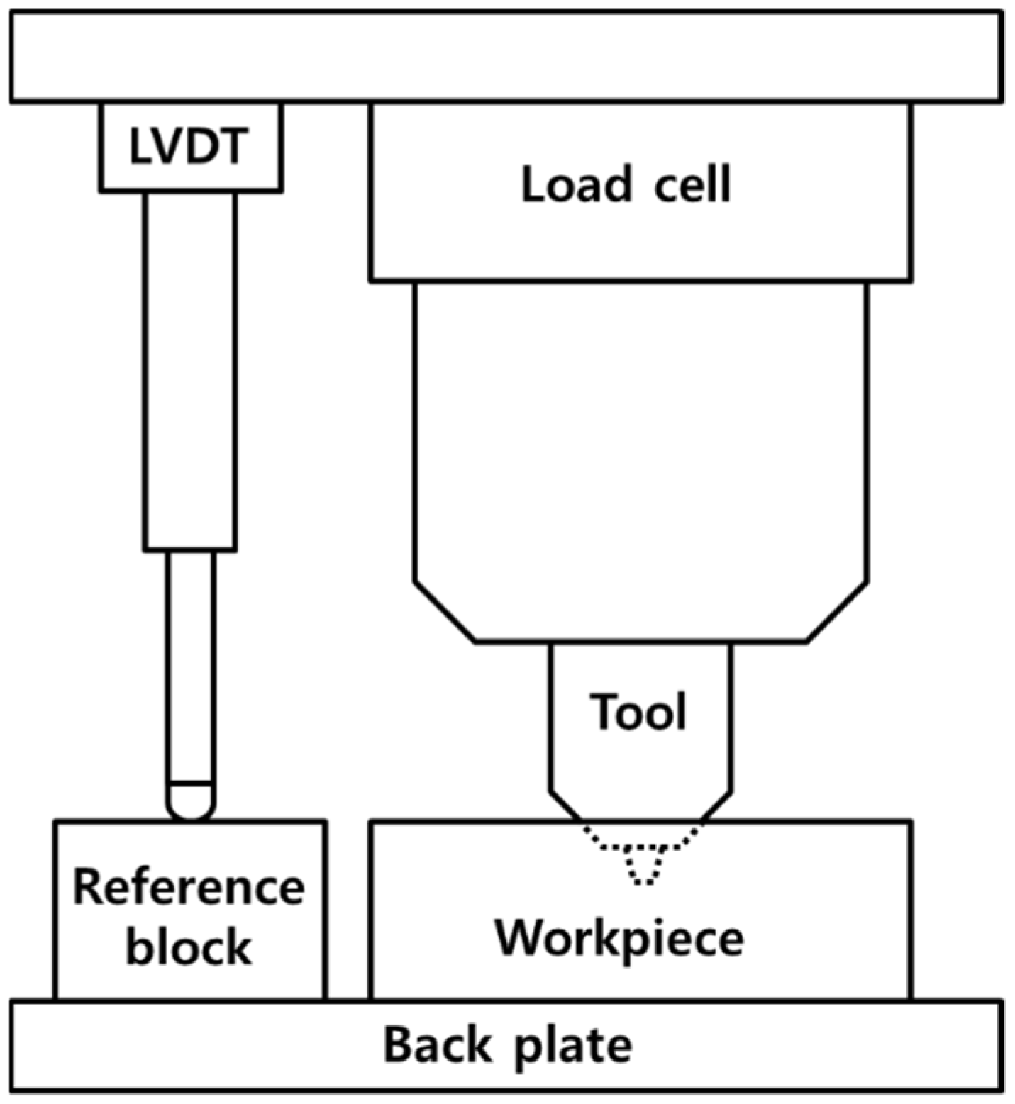
2.1. Experimental Set-Up

The FSSW trials were performed on a 3-axis Cartesian FSW welding system (Hwacheon Machinery, F1300, Gwangju, Korea). This system is a dedicated FSW machine with high stiffness and a zero-degree tilting angle. It has a special interface to correct the vertical position of a welding head using an external signal, which was modified for this study. The tool material was WC-Co12%, and two types of tools were used: a flat shoulder and a conically tapered pin without thread (Figure 1).
The force along the vertical axis was measured using a load cell (Marposs, DDU4, Bentivoglio, Italy) with a resolution of 117 N, and an accuracy of 1.5 kN under a load range of 30 kN. The actual height of the tool was measured for calibration using an LVDT sensor (Marposs, FP50L, Bentivoglio, Italy) with a repeatability of 0.15 μm and a range of 10 mm. The accuracy error of the LVDT sensor varied from 2 μm to 35 μm according to the height of the sensor. The arrangement of the sensing system is shown in Figure 2. The signals from the sensors were collected with a sampling rate of 2 kHz.
Two kinds of experiments were conducted. First, the force profile during the entire process, as well as the relationship between force and deflection, were identified. The base materials were a 12-mm-thick structural mild steel (SS 400), a 4-mm-thick dual phase high-strength steel (DP 590), and a 25-mm-thick Al alloy sheet (Al 1015). FSSW was performed on one sheet as bead-on-plate (BOP) welding with a type I tool. Prior to welding, the profile of the reference position was measured through dry run welding without a workpiece. After welding, the system deflection was calculated from the position error (i.e., the difference between the reference and measured positions). Using data from various base materials and process parameters, a force–deflection model and adaptive height control algorithm were established.
Second, FSSW using the adaptive height control was implemented to evaluate the developed model. The materials were Al 6061-T6 alloy for BOP welds, with Al 6061-T6 alloy on the top and DP 590 steel on the bottom for dissimilar metal lap welds. The plunging speed was 30 mm/min, and other welding parameters varied, as shown in Table 1.

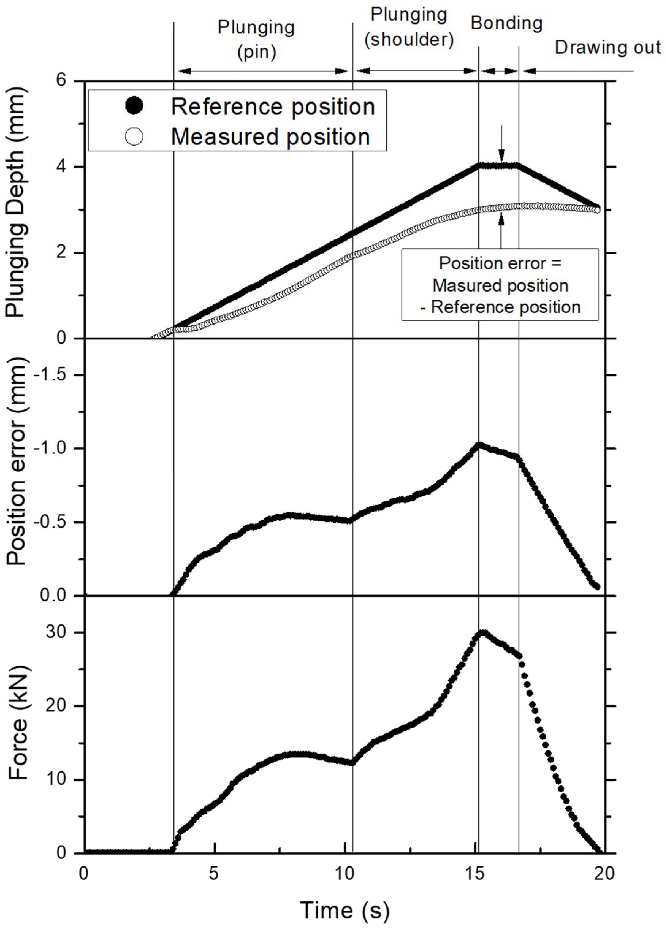
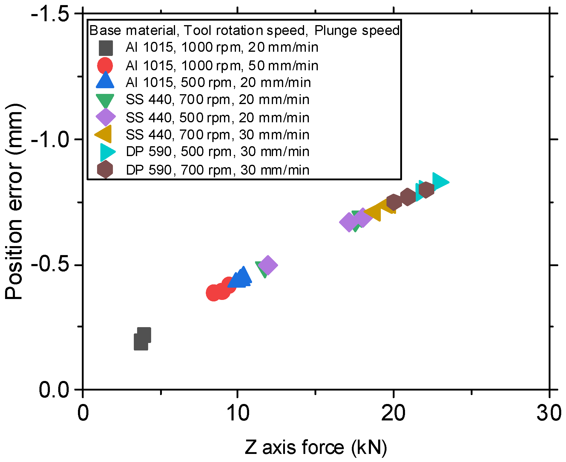
2.2. Force–Deflection Relationship

The profiles of force and actual plunge depth were measured during the entire FSSW process, using a tool with a pin of 2.7 mm in length (Type I), with a tool rotation speed of 500 rpm, a plunging speed of 20 mm/min, and a preset plunge depth of 4 mm. As shown in Figure 3, system deflection initiated as the pin plunged, then increased until the end of the plunging stage. The position error decreased during the bonding stage, owing to greater heat generation and greater plunge depth. While the preset plunge depth was 4 mm, the actual plunge depth was only about 3.1 mm at the end of the bonding stage. During the drawing stage, the position error decreased, then finally disappeared. The pattern of the force profile measured was consistent with that of the position error.
The force–deflection relationship during the plunging stage is shown in Figure 4a. The deflection linearly increased with force in all regions except for the transition zone between ~3 and 4 kN. The relationship was described using Equation 1 and is shown in Figure 4b with the coefficients of determination:
Z d = { 0.0940 + 0.0892 ( 1 + e x p ( x 3.57 . 0.158 ) ) + 0.0341 · x for   0 x < 5 0.0811 + 0.038 · x 0.000229 · x 2 for   x 5
where Zd is the deflection in millimeters and x is the force in kilonewtons, the regression was divided into two sections—more than and less than 5 kN—and linear and sigmoid equations were selected as fitting functions.
In order to confirm the force–deflection relationship over an extensive force range, FSSW for different materials (mild steel, high-strength steel, and Al alloy) with various process parameters was conducted. The measured force and position error at the end of the plunging stage are plotted in Figure 5; the relationship was almost perfectly linear with a slope of 0.0323 mm/kN and a coefficient of determination (R²) of 0.995, regardless of material type or process parameters. This confirms that our force–deflection model was dependent only on the stiffness of the system, but independent of the base materials and process parameters.
Position error due to system deflection was corrected using a feedback control (Figure 6). The feedback system employed a proportional controller to adjust the vertical position using measured force and the force–deflection model. The translation speed of the Z-axis to correct the deflection was programmed according to the amount of position error, as shown in Figure 7. The period of feedback control was 10 μs. Force was measured with a frequency of 2 kHz and an averaged value for each period was used to calculate the deflection. The threshold to initiate feedback control was set to 500 N in order to avoid responding to small and inappropriate disturbances.

3. Results and Discussion

The feedback system developed was examined under various welding conditions in Table 1 and the fixed plunging speed of 30 mm/min. The plunge depth was measured during the BOP welding of an Al 6061 alloy using parameter set No. 3 (Table 1; a preset plunge depth of 2.7 mm, a bonding time of 6 s, a tool rotation speed of 1000 rpm, and a pin of 2.7 mm in length). During the bonding stage, the feedback control system could follow the reference position with an error of 10 μm (Figure 8). In the early plunging stage, an error of not more than 120 μm was observed, reflecting a measured force that was lower than the threshold force of 500 N, below which the position control did not initiate. Without the control system, the welding tool could not reach the preset plunge depth; the maximum position error was 0.36 mm, sufficient to cause a considerable deficiency in welding quality.
The effect of the process parameters on the plunge depth control was examined to verify the robustness of the control method. First, when the preset plunge depth changed from 2.7 mm to 3.3 mm, the plunge depth with feedback control had an error of 20 μm. This error increased with an increase in the preset plunge depth for the without-control experiment because the increase in plunge depth led to increased force (Figure 9a). Second, when the bonding time changed from 3 s to 9 s, the plunge depth was controlled to within an error of 10 μm (Figure 9b). Without the feedback control, an increase in the bonding time led to less error because the longer bonding time caused higher heat generation and temperature in the welds. However, a longer bonding time (i.e., longer process time) is not preferred for most applications. Third, with respect to the tool rotation speed, the error after the feedback control was less than 50 μm (Figure 9c), slightly higher than that of the preceding two cases, but still acceptable when the accuracy of the sensors and the process characteristics of the welding are considered. As with the longer bonding time, higher rotation speeds caused lower error owing to the higher heat generation and temperature in the welds when no feedback control was used. Finally, the feedback control was applied even when the diameters of the shoulder and pin changed from 12 to 8 mm, and 2.7 to 3.2 mm, respectively. The error after feedback control was less than 40 μm (Figure 9d).
The position control was applied in the FSSW of dissimilar metals (Al 6061-T6 alloy and DP 590 steel) using parameter set No. 12 (Table 1; a preset plunge depth of 4.0 mm, a bonding time of 6 s, a tool rotation speed of 1500 rpm, and a pin of 3.2 mm in length). As shown in Figure 10, during the entire process the maximum position errors for plunge depth were about 100 μm with the control, and 600 μm without the control. The position error at the end of the bond stage reflects the plunge depth error in the final welds, which were 30 μm with the control and 300 μm without the control.
The actual penetration of the tool, as measured in cross-sections of welds, was 3.89 mm with the control and 3.55 mm without the control for a preset plunge depth of 4 mm (Figure 11). The penetration on the cross-sections was slightly lower than the plunge depth measured using the sensor. Tensile-shear tests were implemented for three specimens per case, which were prepared according to ISO 14273:2016. The fracture loads in the tensile-shear test were 3.67 kN for the case with control and 2.41 kN for the case without control. The fracture load increased by 52% by achieving deeper plunge depth using the control.
In summary, the vertical deflection of a welding system is linearly proportional to the force for the entire set of base materials and process parameters. Our model, which was established for a specific welding system, could be easily applied without calibration for any combination of material and parameters. During the entire process, the linearity was slightly distorted in the transition region, where the backlash of the system can turn in the opposite direction if the reaction force on the workpiece overcomes the gravity of the welding head. The transition region occurred during the early stages of plunging and did not affect the final position accuracy determined by the plunge depth at the end of the bonding time.
The constant force control system proposed can improve weld quality; however, it does not consider changes in material properties or process parameters according to temperature, which can modify plunge depth and weld quality. Our force–deflection model-based control can be applied using a coaxial load cell without any auxiliary lateral sensors, and will extend the application of FSSW to high-strength and high-temperature softening materials.

4. Conclusions

This study of FSSW aimed to establish a force–deflection model suitable for use with various materials and parameters, and to implement adaptive control of tool height. Deflections are inherently determined by the force and stiffness of the system. The adaptive control developed here will expand the range of FSSW applications for high-temperature softening materials, and should increase the adoption of articulate robots with flexibility but relatively low stiffness. The main conclusions are as follows:
(1)
The deflection of a system is linearly proportional to force and is measurable through a coaxial load cell. The relationship is dependent on nothing but the FSSW system, regardless of the base materials and process parameters (including tool shape).
(2)
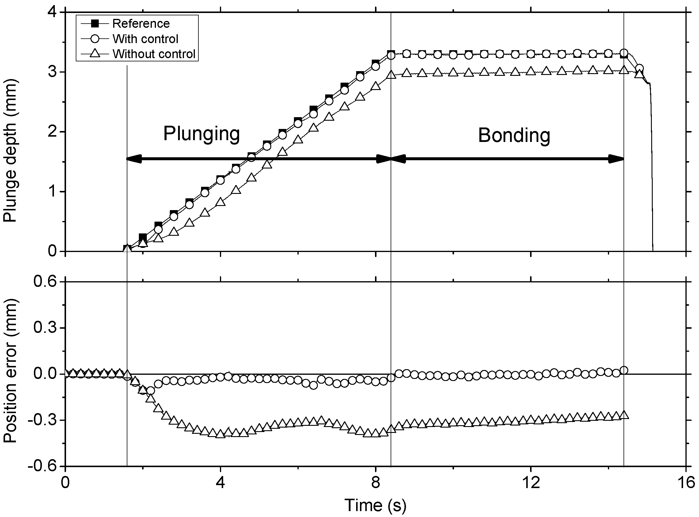
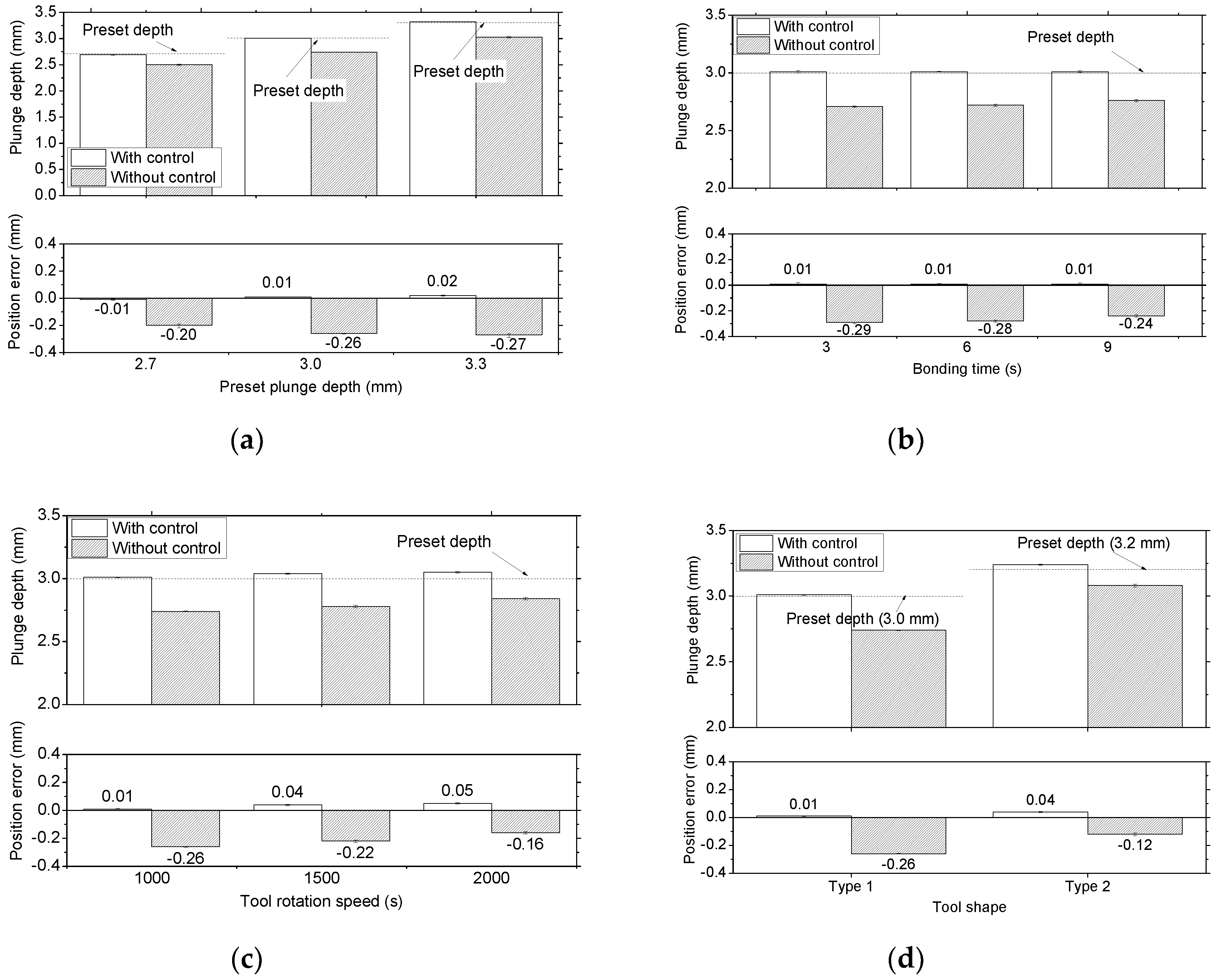
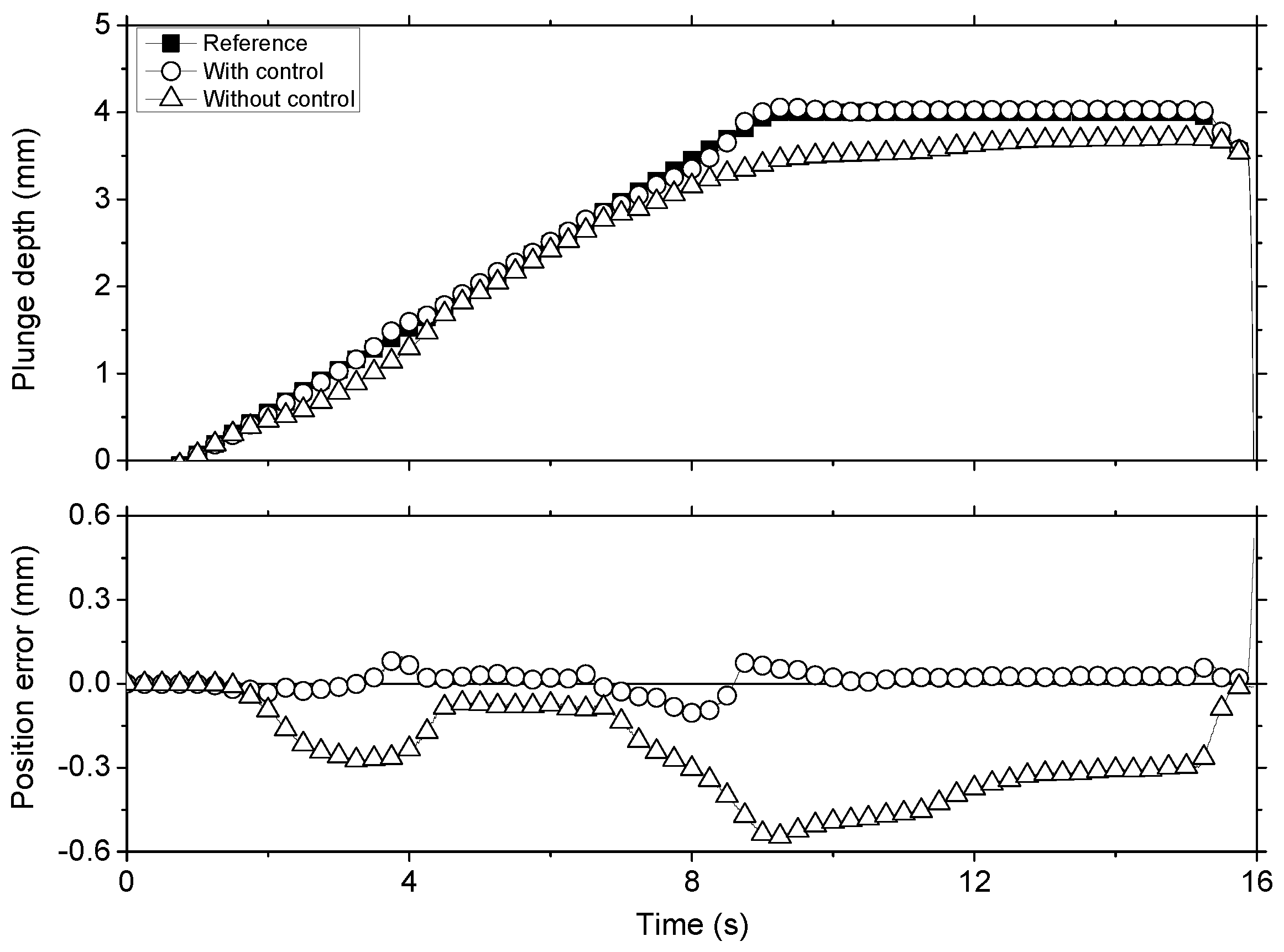
The performance of the suggested control method was evaluated during the BOP FSSW of an Al alloy. Under varying welding conditions, the position error was corrected to under 50 μm (compared with 0.28 mm when the control was not applied).
(3)
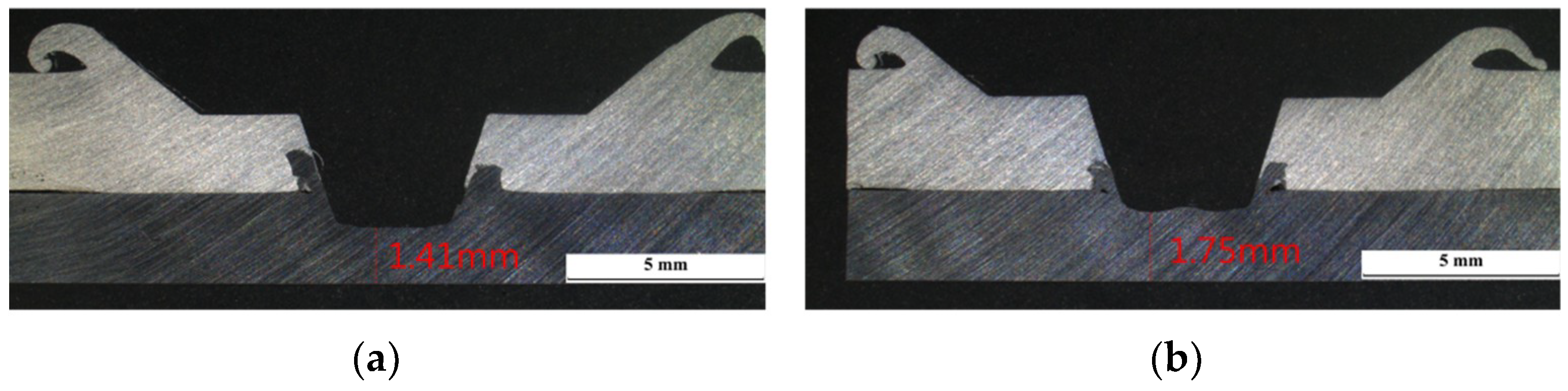
The adaptive control for the plunge depth was successfully implemented in the FSSW of an Al/Fe dissimilar metal joint. The welding tool could plunge to the preset depth with an error of 30 μm. In the cross-section of welds, the plunge depth was almost equal to the preset depth, and a sufficiently high hook was formed to ensure the designed joint strength.

Author Contributions

Investigation, J.Y.; Methodology, J.Y. and C.K.; Supervision, C.K. and S.R.; Writing—original draft, J.Y.; Writing—review and editing, C.K.

Funding

This research was supported by the Ministry of Trade, Industry and Energy, Korea.

Acknowledgements

The authors would like to thank Young-Pyo Kim and staff of Hwacheon Machinary for their kind assistance with tailoring the friction stir welding system.

Conflicts of Interest

The authors declare no conflict of interest.

References

  1. Thomas, W.; Nicholas, E.; Needham, J.C.; Murch, M.; Templesmith, P.; Dawes, C. Friction Stir Welding. Patent No. PCT/GB92102203, 1 December 1991. [Google Scholar]
  2. Threadgill, P.; Leonard, A.; Shercliff, H.; Withers, P. Friction stir welding of aluminium alloys. Int. Mater. Rev. 2009, 54, 49–93. [Google Scholar] [CrossRef]
  3. Mishra, R.S.; Ma, Z. Friction stir welding and processing. Mater. Sci. Eng. R Res. 2005, 50, 1–78. [Google Scholar] [CrossRef]
  4. Nandan, R.; DebRoy, T.; Bhadeshia, H. Recent advances in friction-stir welding–process, weldment structure and properties. Prog. Mater Sci. 2008, 53, 980–1023. [Google Scholar] [CrossRef]
  5. Lee, W.-B.; Jung, S.-B. The joint properties of copper by friction stir welding. Mater. Lett. 2004, 58, 1041–1046. [Google Scholar] [CrossRef]
  6. Thomas, W.; Threadgill, P.; Nicholas, E. Feasibility of friction stir welding steel. Sci. Technol. Weld. Join. 1999, 4, 365–372. [Google Scholar] [CrossRef]
  7. Lienert, T.; Stellwag, W., Jr.; Grimmett, B.; Warke, R. Friction stir welding studies on mild steel. Weld. J. 2003, 82, 1s–9s. [Google Scholar] [CrossRef]
  8. Ramirez, A.J.; Juhas, M.C. Microstructural evolution in Ti-6Al-4V friction stir welds. Mater. Sci. Forum 2003, 426, 2999–3004. [Google Scholar] [CrossRef]
  9. Prado, R.; Murr, L.; Shindo, D.; Soto, K. Tool wear in the friction-stir welding of aluminum alloy 6061+Al2O3: A preliminary study. Scripta Mater. 2001, 45, 75–80. [Google Scholar] [CrossRef]
  10. Hirano, S. Microstructure of dissimilar joint interface of magnesium alloy and aluminum alloy by friction stir welding. Q. J. Jpn. Weld. Soc. 2003, 21, 539–544. [Google Scholar] [CrossRef]
  11. Lee, W.-B.; Schmuecker, M.; Mercardo, U.A.; Biallas, G.; Jung, S.-B. Interfacial reaction in steel–aluminum joints made by friction stir welding. Scripta Mater. 2006, 55, 355–358. [Google Scholar] [CrossRef]
  12. Kimapong, K.; Watanabe, T. Friction stir welding of aluminum alloy to steel. Weld. J. 2004, 83, 277s–282s. [Google Scholar]
  13. McLean, A.; Powell, G.; Brown, I.; Linton, V. Friction stir welding of magnesium alloy AZ31B to aluminium alloy 5083. Sci. Technol. Weld. Join. 2003, 8, 462–464. [Google Scholar] [CrossRef]
  14. Chen, Y.C.; Nakata, K. Microstructural characterization and mechanical properties in friction stir welding of aluminum and titanium dissimilar alloys. Mater. Des. 2009, 30, 469–474. [Google Scholar] [CrossRef]
  15. Yang, X.W.; Fu, T.; Li, W.Y. Friction Stir Spot Welding: A Review on Joint Macro- and Microstructure, Property, and Process Modelling. Adv. Mater. Sci. Eng. 2014, 2014. [Google Scholar] [CrossRef]
  16. Nguyen, N.-T.; Kim, D.-Y.; Kim, H.Y. Assessment of the failure load for an AA6061-T6 friction stir spot welding joint. Proc. Inst. Mech. Eng. Pt. B J. Eng. Manuf. 2011, 225, 1746–1756. [Google Scholar] [CrossRef]
  17. Gerlich, A.; Su, P.; North, T.H. Tool penetration during friction stir spot welding of Al and Mg alloys. J. Mater. Sci. 2005, 40, 6473–6481. [Google Scholar] [CrossRef]
  18. Mendes, N.; Neto, P.; Loureiro, A.; Moreira, A.P. Machines and control systems for friction stir welding: A review. Mater. Des. 2016, 90, 256–265. [Google Scholar] [CrossRef]
  19. Smith, C.B. Robotic friction stir welding using a standard industrial robot. In Proceedings of the Second Friction Stir Welding International Symposium, Gothenburg, Sweden, 26–28 June 2000; TWI Ltd.: Cambridge, UK, 2000. [Google Scholar]
  20. Fehrenbacher, A.; Smith, C.B.; Duffie, N.A.; Ferrier, N.J.; Pfefferkorn, F.E.; Zinn, M.R. Combined Temperature and Force Control for Robotic Friction Stir Welding. J. Manuf. Sci. Eng. 2014, 136. [Google Scholar] [CrossRef]
  21. Gibson, B.T.; Lammlein, D.H.; Prater, T.J.; Longhurst, W.R.; Cox, C.D.; Ballun, M.C.; Dharmaraj, K.J.; Cook, G.E.; Strauss, A.M. Friction stir welding: Process, automation, and control. J. Manuf. Process. 2014, 16, 56–73. [Google Scholar] [CrossRef]
  22. Longhurst, W.R.; Strauss, A.M.; Cook, G.E.; Cox, C.D.; Hendricks, C.E.; Gibson, B.T.; Dawant, Y.S. Investigation of force-controlled friction stir welding for manufacturing and automation. Proc. Inst. Mech. Eng. Pt. B J. Eng. Manuf. 2009, 224, 937–949. [Google Scholar] [CrossRef] [Green Version]
  23. Guillo, M.; Dubourg, L. Dual control loop force/position with secondary encoders: Impact & improvement of industrial robot deviation on FSW quality. In Proceedings of the 11th International Symposium on Friction Stir Welding, Cambridge, UK, 17–19 May 2016. [Google Scholar]
  24. Gibson, B.T.; Cox, C.D.; Longhurst, W.R.; Strauss, A.M.; Cook, G.E. Exploiting robotic link deflection for low-cost force measurement in manufacturing. Measurement 2012, 45, 140–143. [Google Scholar] [CrossRef]
  25. De Backer, J.; Bolmsjö, G. Deflection model for robotic friction stir welding. Ind. Robot. Int. J. 2014, 41, 365–372. [Google Scholar] [CrossRef]
  26. Cederqvist, L.; Garpinger, O.; Nielsen, I. Depth and Temperature Control During Friction Stir Welding of 5 cm Thick Copper Canisters. In Friction Stir Welding and Processing IX; Hovanski, Y., Mishra, R., Sato, Y., Upadhyay, P., Yan, D., Eds.; Springer: Cham, Switzerland, 2017; pp. 249–260. [Google Scholar]
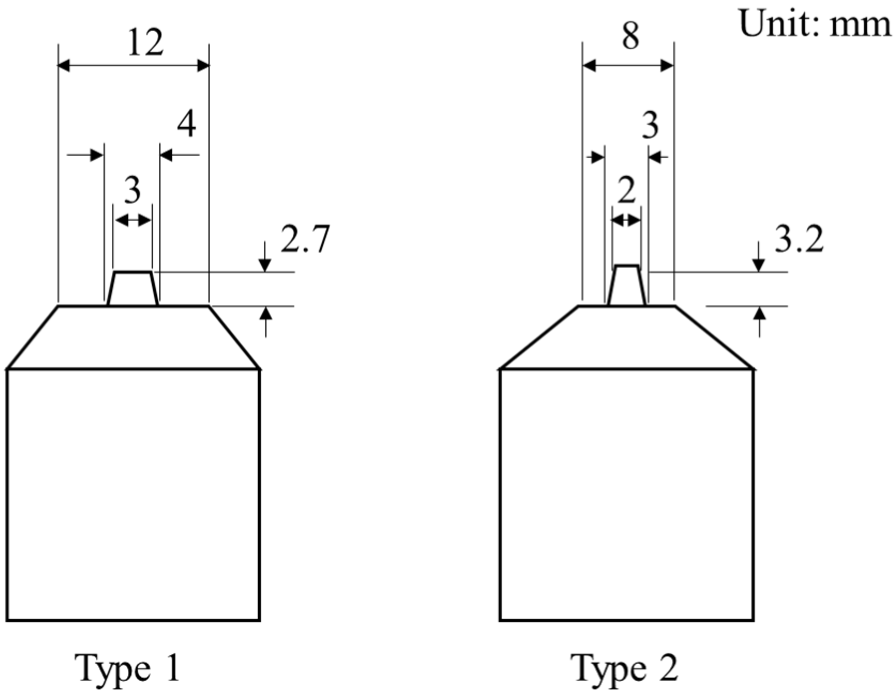
Figure 1. Shapes of welding tools (all dimensions in mm).
Metals 08 01049 g001
Figure 2. Set-up of the sensing system.
Metals 08 01049 g002
Figure 3. Measured profiles of plunge depth, deflection, and force during friction stir spot welding (FSSW) of steel (SS400).
Metals 08 01049 g003
Figure 4. Deflection according to force during the plunging stage for the (a) measured data and (b) fitted results.
Metals 08 01049 g004
Figure 5. Measured force and deflection at the end of the plunging stage.
Metals 08 01049 g005
Figure 6. Feedback controller block diagram.
Metals 08 01049 g006
Figure 7. Z-axis translation speed according to position error.
Metals 08 01049 g007
Figure 8. Comparison of plunge depth as a function of process time with and without feedback control (parameter set No. 3; Table 1).
Metals 08 01049 g008
Figure 9. Effect of process parameters (parameter details given in Table 1) for (a) preset plunge depth (exp. No. 1–3), (b) bonding time (exp. No. 4–6), (c) tool rotation speed (exp. No. 7–9), and (d) tool shape (exp. No. 10 and 11).
Metals 08 01049 g009
Figure 10. Comparison of the plunge depth as a function of time with and without feedback control (parameter set No. 12; Table 1).
Metals 08 01049 g010
Figure 11. Cross-sections of friction stir spot welding (FSSW) for dissimilar metals (a) with and (b) without control (plunge depth: 4 mm; stirring time: 6 s; tool rotation speed: 1500 rpm; material: Al 6061-T6 alloy (top) and SPFC 590 dual phase (DP) steel (bottom)).
Metals 08 01049 g011
Table 1. Welding parameters for the experiments.
Experiment No.Plunge
Depth (mm)
Bonding
Time (s)
Tool Rotation Speed (rpm)Tool
Shape
MaterialThickness
(mm)
12.761000Type 1Al 6061-T64
236
33.36
433
536
639
736
8361500
9362000
10361000
113.26Type 2
12461500Al6061-T6/
DP 590
3 (upper)/2.3 (lower)

