Article

A Study on Two-Stage Cold Forging for a Drive Shaft with Internal Spline and Spur Gear Geometries

Engineering Research Center of Innovative Technology on Advanced Forming, Pusan National University, Geumjeong-gu, Busan 46241, Korea
Metals 2018, 8(11), 953; https://doi.org/10.3390/met8110953
Submission received: 2 November 2018 / Revised: 12 November 2018 / Accepted: 13 November 2018 / Published: 15 November 2018

Abstract

:
A two-stage cold forging process was proposed to manufacture a drive shaft with an internal spline and spur gear geometries, and this process was mainly composed of a forward extrusion for preform and a forward-backward extrusion for the drive shaft. In the process design, the preform was designed using a volume apportioning scheme from the required target shape, thereafter, the initial round billet was outlined. AISI 1035 carbon steel was selected as the raw material, and a spheroidizing heat treatment was adopted. Using the raw and spheroidizing annealed workpieces, uni-axial tensile and compression tests were carried out to evaluate the effect of the heat treatment and to measure the mechanical properties. Finite element simulations were sequentially performed to assure the suitability of the proposed process design. Considering the results from the process design and the numerical simulations, the related tool components were prepared and applied to a series of experimental investigations. The preform and the drive shaft fabricated by the two-stage cold forging experiments were compared with the required target and the numerically predicted configurations. The results indicated that the two-stage cold forging process proposed in this study could be well applied to the production of the drive shaft with an internal spline and spur gear structures.

Graphical Abstract

1. Introduction

As mechanical joints, gears and splines are mainly used for transmitting rotational motion and torque from a power source to other functional members and structures. In particular, the spline formed at the longitudinally expanded end along the shaft of the power source is connected to the internal spline configured at the end of the other shaft member on the same axis, so the rotational motion and the torque can be directly transferred to the other mechanical component [1]. In addition, the gear plays an important function in changing the speed, torque, and direction of the transmitted power [2,3]. With regard to the manufacturing method used for the spline and the gear, forging processes and machining sequences, including material removal are widely adopted. However, these components as the mechanical-structural metal member are basically required to have high strength and high structural stiffness against the torque, as well as high wear-resistance and durability characteristics. In order to satisfy these requirements, a series of inherent defects such as void and micro-crack, as well as residual stress derived from plastic deformation of the workpiece, should be eliminated or minimized [4]; thus, the metal forging process is more widely recommended than material removal and machining as an acceptable production scheme [5,6].
The drive shaft dealt with in this study has the distinct feature of an irregular hexadecagonal deep groove as the internal spline at the upper head region, as well as a sixteen-tooth spur gear along its shaft section. Thus, the cold forging process for manufacturing the drive shaft with the spur gear and the internal spline geometries in a long shaft member becomes more complicated. For example, a forward extrusion for shaping the spur gear and a backward operation for configuring the internal spline are both needed. Most recent issues related to metal forging technology are associated with pursuing the goals of process simplification and improving the efficiency to increase the productivity and enhancei the yield percentage of material, as well as reducing the manufacturing cost [7,8]. A variety of research activities to address these issues caused by the complexity of the target geometry have been ongoing in various forging fields, and several combined forging processes have been introduced and reported [9,10]. Because this combined forging process is classified as merging similar or different sequences adjoining each other into one simplified procedure, it is essential that the mechanical properties of the billet workpiece have enough workability and forgeability. These mechanical properties and material characteristics can be provided and improved through suitable material selection and a series of heat treatments such as spheroidizing and annealing, and so forth [11,12,13,14,15].
In this study, a two-stage cold forging process was proposed and was composed of both the forward extrusion for shaping the preform and the forward-backward extrusion for obtaining a drive shaft with an internal spline and spur gear geometries. With respect to the process design, the preform was designed in a reverse manner based on the required target configuration, after which the initial billet shape was also defined. AISI 1035 medium carbon steel was used as the billet material. In order to avoid severe defects induced from excessive plastic deformation and to improve the forgeability, the AISI 1035 raw round billet was heat treated by spheroidizing annealing. Thereafter, uni-axial tensile and compression tests were performed to evaluate and compare the mechanical properties between the raw and the annealed materials. The relevance of the process design result was evaluated through three-dimensional finite element simulations using DEFORM-3D™. In addition, the two-stage cold forging experiments were carried out to fabricate the drive shaft. With regard to the dimensional suitability of the internal spline and the spur gear geometries, the obtained preform and the fabricated drive shaft were compared to the results extracted from the numerical simulations and the process design. Finally, it was confirmed that the two-stage cold forging process proposed for fabrication of the drive shaft in this study could be sufficiently visualized with good agreement for the required dimensional accuracy, as well as successfully realized by the actual manufacturing scheme, and directly applied to mass production with three-dimensional complicated geometries.

2. Materials and Methods

2.1. Description of Drive Shaft

In view of the general geometric characteristics, the spur gear is defined as having many teeth and straight profiles on the circumferential surface along the longitudinal direction of the round shaft, and the internal spline corresponding to the external one formed at the shaft end of the other member also has several grooves or ridges. Especially, the drive shaft in this study has a distinct feature in that the internal spline and the spur gear are conjoined into one piece, and it is in charge of the key functions of transmitting rotational power and torque obtained from a prime mover into the inner actuator in a hydraulic pump for general industrial machinery. In detail, this drive shaft consists of the internal spline shape on the upper head region and the spur gear geometry on the shaft. Furthermore, the internal spline structure of the drive shaft was designed with the cross-sectional shape of the irregular hexadecagonal deep groove as a type of 8-point star lug nut and the sixteen-tooth spur gear geometry configured on the circumferential surface along the longitudinal direction of the cylindrical shaft.
Figure 1a presents the three-dimensional configuration of the drive shaft, and the rough geometries are required to be at a minimum depth of 22.7 mm for the irregular hexadecagonal deep groove, a minimum height of 36.5 mm for the upper head, and an extruded length of 92.0 mm for the face width of each tooth in the spur gear, as well as a minimum length of 35.0 mm for the lower shaft, so that ultimately there is a total length of roughly 169.5 mm for the drive shaft. It is also shown that the outer diameter of the upper head was designed to be 51.6 mm, and that of the lower shaft was 36.7 mm. In addition, the shoulder angle between the upper head region and the spur gear area was set to be 45.0°, and the slope angle between the top land on each tooth of the spur gear and the lower shaft was set to be 45.0°. The drive shaft presented in this study, is a mechanical-structural component installed in a hydraulic pump, with the material properties exhibiting high strength and structural stiffness, high wear-resistance characteristics, and high durability.

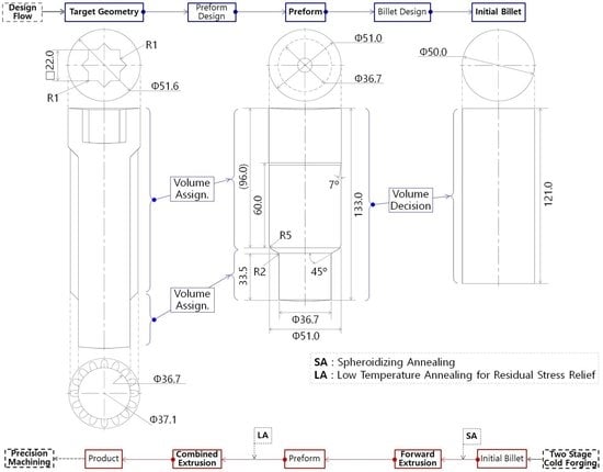
2.2. Process Design for Two-Stage Cold Forging

Because the drive shaft shown in Figure 1a has a whole length of more than about 169.5 mm and includes the different cross-sectional configurations along the longitudinal direction of the shaft, if a single cold forging operation is applied to obtain the drive shaft from the initial round billet, it is hard to realize the final product without crucial defects, such as material damage and surface cracks caused by excessive plastic deformation. To avoid these defects, the preform or the intermediate workpiece is commonly applied in many cases of manufacturing the mechanical-structural metal components with a high degree of difficulty in the target geometry [8,16,17]. By doing so, the excessive plastic deformation and critical defects can be prevented in advance. On the other hand, the mechanical strength of the raw material, as well as the elongation, can be improved through a series of heat treatments including spheroidizing and annealing [13,18].
With the aforementioned considerations and the volume constant condition, the two-stage cold forging process was designed in a reverse manner because the required final shape and geometries were defined as shown in Figure 1a. Specifically, the diameter of 36.7 mm and the extruded length of 35.0 mm at the lower shaft part of the final target configuration were determined to be induced from the preform operation, so the dimensions at the lower extruded part of the preform were designed to be the same, and the remaining volume of the upper head and the spur gear shaft was apportioned to the upper head section of the preform. Finally, based on the determined feature of the preform, the initial billet with a diameter of 50.0 mm and a height of 121.0 mm was visualized. Figure 1b shows the results of the process design for the two-stage cold forging of the drive shaft. In contrast, the two-stage cold forging process is sequentially carried out. That is, the spheroidized and annealed initial round billet material is deformed to the preform through the forward extrusion. Thereafter, the cold extruded preform is heat treated by a low-temperature annealing process, which is powerful enough to eliminate the residual stress caused by the forward extrusion without microstructural change. Also, the stress relieved preform is cold forged by the forward-backward extrusion, then the upper head region and the spur gear shaft are configured so as to reach the minimum depth of about 22.7 mm for the irregular hexadecagonal deep groove as the internal spline and the top land width of about 92.0 mm on the extruded spur gear along the shaft, without any additional deformation at the lower shaft.

3. Mechanical Properties and Finite Element Models

3.1. Mechanical Properties of AISI 1035 Carbon Steel

Due to the fact that the drive shaft is a metal member of the power system in the industrial hydraulic pump, the shaft material is required to satisfy several characteristics such as high strength and structural stiffness against the torque, high wear-resistance and durability, and so on. In this study, AISI 1035 medium carbon steel as a cold drawn round bar was selected as the raw billet material [15]. The AISI 1035 raw billet workpiece is well-known as a mechanical-structural material with its chemical composition summarized in Table 1. This round bar was first cut so as to meet the design dimensions of the initial billet with a diameter of 50.0 mm and a height of 121.0 mm. From the results of the process design shown in Figure 1b, because the severe plastic deformation during the cold forging operations was predicted, it was necessary to improve and ensure the forgeability and ductility of the workpiece material. Thus, the raw billet materials were heat treated through spheroidizing annealing at a temperature of 760 °C for eight hours. Moreover, the microstructures before and after the spheroidizing annealing were observed with a high magnification factor of 500 using the OM (Optical Macroscopy) apparatus of Olympus BX51M. The average grain size of the raw AISI 1035 material was measured at a value of about 8.84 μm, while that of the spheroidized and annealed specimen was evaluated at roughly 9.36 μm, it was also revealed that the microstructure of the AISI 1035 medium carbon steel was well spheroidized, as shown in Figure 2.
Additionally, a series of uni-axial tensile and compression tests for the raw and the spheroidizing annealed AISI 1035 specimens were carried out. The round-type specimens for the uni-axial tensile test and the cylinder-type samples for the compression experiment were prepared with the ASTM E8/E8M and the ASTM E9-09 standard specifications, respectively. Hereby, the uni-axial tensile tests were first performed to investigate the tensile properties. As for the results, the true stress-strain curves are presented in Figure 3a, then it was observed that the yield and ultimate strengths after the spheroidizing annealing were slightly decreased from 410 MPa to 350 MPa and from 755 MPa to 643 MPa, respectively. However, the elongation after the spheroidizing annealing increased with a value of roughly 13.76%. The tensile properties before and after the spheroidizing annealing are summarized in Table 2. Furthermore, the compression tests to evaluate and verify the relevance of the compressive strength level were performed using circular specimens with a diameter of 8.00 mm and a height of 6.40 mm. Figure 3b displays the compressive engineering stress-strain curves before and after the spheroidizing annealing. The compressive yield strength and the ultimate limit for the heat-treated specimen were slight decreased, but these strength levels are meant to be sufficient for the two-stage cold forging to produce the drive shaft. Based on the results obtained from the uni-axial tensile and the compression tests, it can be summarized that the spheroidizing annealed AISI 1035 medium carbon steel can provide the necessary mechanical properties such as a yield strength of about 350 MPa and an ultimate limit of roughly 643 MPa, as well as an elongation of approximately 32.10% in the tensile mode, and that the compressive characteristics were also sufficient. These mechanical properties were used in a series of numerical simulations of the two-stage cold forging for fabricating the preform and the drive shaft.

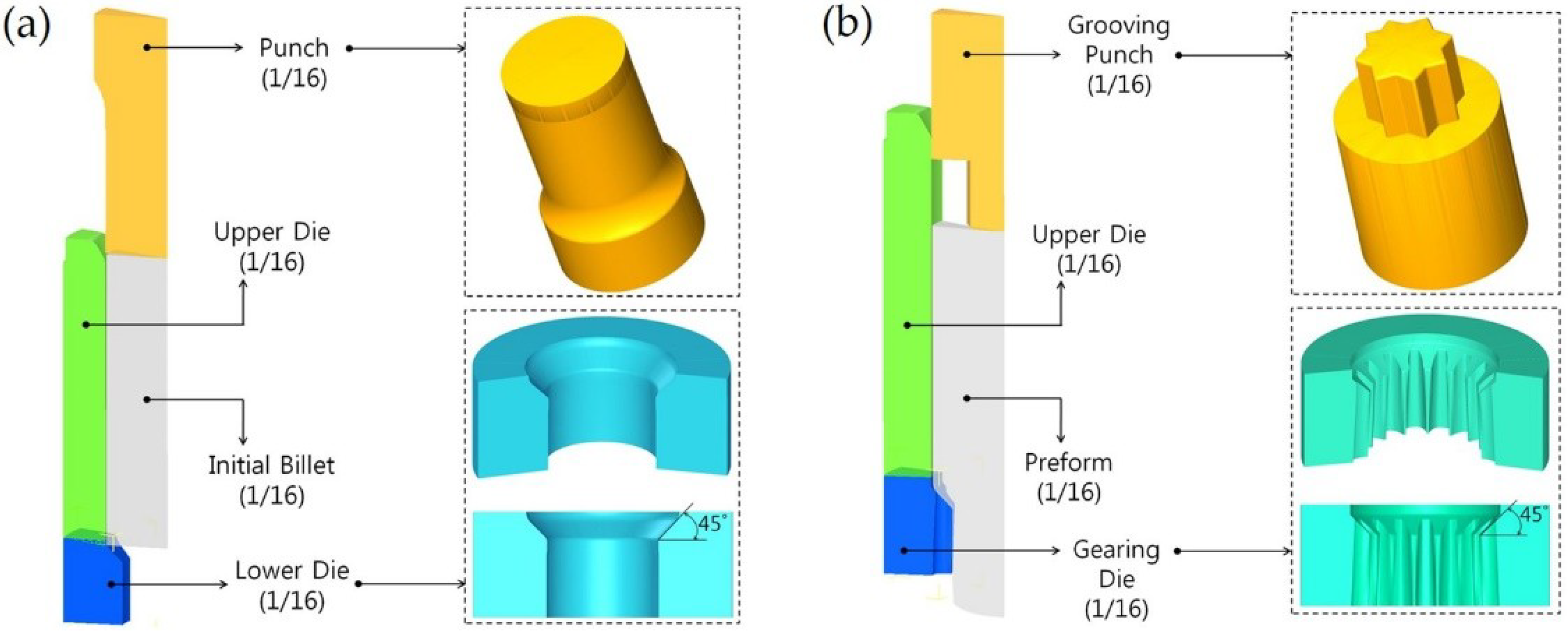
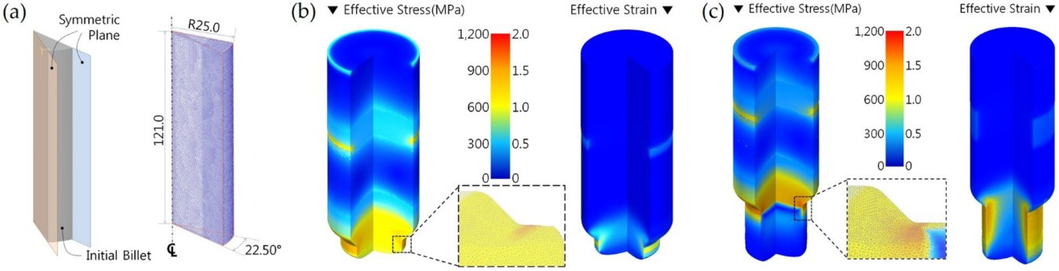
3.2. Three-Dimensional Finite Element Models

The results of the process design shown in Figure 1b reveal that the two-stage cold forging process is mainly composed of the forward extrusion for fabricating the preform, and the forward-backward extrusion for realizing the internal spline with the irregular hexadecagonal deep groove on the upper head region as well as for shaping the sixteen-tooth spur gear on the drive shaft. This means that each FE model for FEM-based numerical simulations is necessary for these separate forging operations. Thus, an FE model related to the forward extrusion has to be constructed, and a model for the forward-backward extrusion must also be built-up. Here, the preform can be easily obtained by the simple forward extrusion using the round workpiece, and can even seem like a 2-dimensional axi-symmetric problem. However, the forward-backward extrusion operation must ensure a symmetric constraint due to the irregular hexadecagonal deep groove of the upper head region, as well as the tooth profile and its arrangement on the spur gear shaft area. To visualize the symmetric condition, the overlapped layout with regard to the main cross-sections of the drive shaft was illustrated as shown in Figure 4. Clearly, Figure 4a indicates the representative tooth profile within the spur gear shaft region, and Figure 4b visualizes the overlapped layouts that consist of the cross-sections at the upper head and the spur gear shaft regions, as well as the lower shaft. The geometries of the spur gear with sixteen teeth on the circumferential surface of the shaft are presented in Figure 4a. It was revealed that the root radius of the teeth is 18.55 mm, which is 0.20 mm larger than the outer radius of 18.35 mm on the lower shaft. As shown in Figure 4b, the internal spline at the upper head region has a three-dimensional one-sixteenth (1/16) symmetric feature, and the spur gear also has a one-thirty-second (1/32) symmetric shape. Due to the symmetric characteristics of the drive shaft, determination of the minimum symmetric shape for assuming the boundary condition of the numerical simulation models and reducing the computation time of the two-stage cold forging was needed. Using both symmetric configurations, three-dimensional FE models for the forward extrusion and the forward-backward extrusion were constructed by adopting a one-sixteenth (1/16) symmetric boundary condition.
Figure 5 illustrates both FE models with the one-sixteenth (1/16) symmetric condition. The three-dimensional FE model in Figure 5a shows the forging punch and the dies to simulate the forward extrusion process, and Figure 5b displays the backward extrusion punch and the forward extrusion-gearing die to realize the drive shaft by the forward-backward forging. In addition, Figure 5 includes the die shapes to form the preform and the spur gear, then, each shoulder angle of the lower and gearing dies was set to be 45.0° based on the results of the process design. All numerical simulations in this study were performed using a commercial software, DEFORM-3D™ (Scientific Forming Technologies Corporation, Columbus, OH, USA). An automatic remeshing scheme was also adopted as a useful technique to reduce the computation time and restrain the analytic errors from the excessive distortion and warpage on the mesh shape. In the FEM-based numerical simulations, all tool structures such as the punches and the dies were assumed to be rigid bodies, and the initial billet was regarded as a deformable body with plastic deformation behavior. Particularly, because the initial round billet and the preform were defined as one-sixteenth symmetric FE models, the boundary conditions for both billets were also assumed to have one-sixteenth cyclic planar symmetry. The two-stage cold forging process in this study was defined as a quasi-static process, so any influence of the strain rate was disregarded. As for the other consideration, the friction coefficient between the tool components and the workpieces was assumed to be 0.098 as the shear friction behavior, during the two-stage cold forging operations were performed, because the surface of the spheroidized and annealed billet material was treated to reduce the friction effect by a phosphophyllite coating (Zn2Fe(PO4)2) [8,12,13].

4. Numerical Simulations

4.1. Forward Extrusion Simulation for Preform

Because the final target configuration has one-sixteenth cyclic planar symmetry as shown in Figure 4b, the initial billet was also modeled with the same boundary condition and discretized by 257,678 tetrahedral elements. The detailed dimensions and mesh structure are shown in Figure 6a, along with the boundary conditions. In particular, these tetrahedral elements arranged around the outside of the initial billet were more densely distributed than the inside region. Using the FE model described in Figure 5a and the discretized initial billet in Figure 6a, the numerical simulation related to the forward extrusion was carried out. In the cold forward extrusion simulation, the initial billet was compressed by the forward extrusion punch described in Figure 6a. In detail, as illustrated in Figure 6b, when the punch stroke runs to nearly 53%, the effective stress and the effective strain were predicted to be roughly 984 MPa and 1.49. In addition, these values in case of the punch stroke of 100% were also evaluated to be about 1160 MPa and 1.98, as displayed in Figure 6c. It was also observed that the maximum effective stress and strain occurred around the shoulder region of the deform workpiece, because the workpiece was actually extruded on that region of the lower die. Considering the compressive mechanical properties displayed in Figure 3b, it was regarded that the predicted effective stresses were appropriately distributed and these levels were not severe.
From Figure 7a, it was also confirmed that the initial billet with a diameter of 50.0 mm and height of 121.0 mm was extruded to be about 135.75 mm along the center line, and also met the designed whole height of 133.0 mm shown in Figure 1b. The desired extrusion length of 33.50 mm was achieved at the obtained value of 33.57 mm, when the punch stroke was about 28.63 mm (100%). In the following operation, low temperature annealing was carried out to remove the residual stress within the preform. The low temperature heat treatment relieved the residual stress of the deformed workpiece without any microstructural change. Thus, all stress values of the plastic deformed preform can be reset to zero as the initial state. This being so, the deformed geometries of the forward extruded preform were directly used as the initial workpiece for the forward-backward extrusion. However, because the drive shaft in this study has complicated features including the internal spline with the irregular hexadecagonal deep groove and the spur gear with the sixteen teeth, the preform as the intermediate workpiece for the forward-backward extrusion simulation was required to reconstruct the mesh structure for more precise configuration of the final target shape. Accordingly, the mesh system of the preform was re-arranged and initialized with 322,882 tetrahedral elements, and the mesh density was also varied to be distributed more densely around the outside and top region of the preform than around the inside region. Figure 7b illustrates the reconstructed mesh structure of the preform for the forward-backward extrusion simulation, and it is ascertainable that the tetrahedral elements are distributed with a higher mesh density around the upper and outside regions than those of the central area of the preform.

4.2. Forward-Backward Extrusion Simulation for Drive Shaft

Using the re-arranged mesh structure and the boundary condition as the cyclic planar symmetry, as well as the three-dimensional configurations of the tool components shown in Figure 5b, the forward-backward extrusion process was simulated. Figure 8 shows the three-dimensionally simulated results, and the cold forging process was completed when the punch stroke reached 89.64 mm. Figure 8a shows the effective stress distributions with punch strokes of 30%, 65% and 100%. Around the shoulder region of the drive shaft, the maximum effective stress of about 1140 MPa was predicted at the punch stroke of 30%, that of roughly 1180 MPa at the punch stroke of 65%, and that of approximately 1170 MPa at the punch stroke of 100%. In addition, the maximum effective strain of about 2.84 was measured at the punch stroke of 30%, that of roughly 3.33 at the punch stroke of 65%, and that of about 3.19 at the punch stroke of 100%, as illustrated in Figure 8b. Furthermore, Figure 8c depicts the maximum stress and strain distributions at the top and the bottom views, and it was revealed that the internal spline with the irregular hexadecagonal deep groove at the upper head region was well extruded in a backward manner, and that the sixteen teeth on the spur gear shaft were also precisely formed.

4.3. Forging Load Predictions

In the cold forging process, the forging load prediction is important because it can be helpful in determining the forging press capacity. Therefore, the cold forging loads were numerically estimated, and Figure 9 depicts the load histories for the forward extrusion and the forward-backward extrusion with the accumulated punch stroke. In the forward extrusion for obtaining the preform, the punch stroke was required to be about 28.63 mm, and the maximum forging load required for the forging punch was predicted to be roughly 240 Tonf, with the average load being approximately 210 Tonf. It was also shown that the maximum compressive load that acted on the lower die was estimated to be nearly 190 Tonf, and the average load was already 175 Tonf. Subsequently, the punch stroke for the forward-backward extrusion was required to be about 89.64 mm (that is, the accumulated stroke was nearly 118.27 mm). The cold forging load for extruding the preform into the drive shaft was calculated to be the maximum value of about 215 Tonf and the average value of roughly 180 Tonf for the punch, while the compressive loads delivered to the lower die were estimated to be the maximum value of approximately 195 Tonf and the average one of 170 Tonf, respectively. From the predicted results, it was estimated that the required forging load for the forward extrusion was slightly larger than that for the forward-backward operation. Considering a safety margin of over 100% so as to avoid the structural deflection and severe failure of the cold forging press, the proper capacities of both cold forging presses were determined to be about 480 Tonf and 320 Tonf for each extrusion operation. Thus, it can be summarized that the forging press with a capacity of roughly 500 Tonf is admissible for the forward extrusion and the forward-backward operation. With regard to the compressive load acting on the lower die, as the load levels were not severe, it appears that structural stiffness and integrity can be provided by selecting suitable tool materials [11].

5. Cold Forging Experiments for the Preform and Drive Shaft

As a of mechanical-structural carbon steel material, AISI 1035 cold-drawn round material was used as the initial round billet in this study because this medium carbon steel is mainly applied to various metal components such as levers, bolts, studs, nuts, axle shafts and arm parts, in which relatively high strength properties are required. First, the initial round billet with a diameter of 50.0 mm and height of 121.0 mm was processed by the spheroidizing annealing operation, and the phosphophyllite (Zn2Fe(PO4)2) coating on the round workpiece was then applied to alleviate the friction behavior between the tool surfaces and the workpiece. Based on the aforementioned results of the spheroidizing annealing, the microstructure of the raw AISI 1035 billet material was well spheroidized, as shown in Figure 2, and the mechanical properties were also improved, as presented in Figure 3. Furthermore, the tensile characteristics, as well as the improved workability and forgeability of the spheroidizing annealed AISI 1035 medium carbon steel, were compared to those of the raw material, as summarized in Table 2.
Following the phosphophyllite coating on the spheroidizing annealed AISI 1035 initial round billet, the forward extrusion for fabricating the preform was carried out. The tool components were prepared with consideration of the tool geometries of Figure 5a, and applied to the forward extrusion experiment for obtaining the preform. For the forward extrusion experiment, a hydraulic press with a cold forging load capacity of 600 Tonf was adopted, because the press capacity was recommended to be roughly 500 Tonf from the forging load prediction on the forward extrusion process. Figure 10a shows the preform fabricated by the cold forward extrusion experiment. It was observed that the preform was well forged in terms of external appearance.
In the cold forward extrusion sequence, the residual stress may be inherent in the fabricated preform. If the preform with the inherent residual stress is directly applied to the forward-backward extrusion operation, the probability of the occurrence of severe damage and mechanical performance degradation also increases with the accumulation of the residual stress. To prevent this possibility in the cold forging process, a low temperature annealing process was applied to the preform fabricated by the cold forward extrusion, because this heat treatment can remove the residual stress without any change in the microstructural shape and its characteristics. Using the low temperature annealed preform, the forward-backward extrusion operation for manufacturing the drive shaft was performed experimentally. The tool sets, such as the irregular hexadecagonal deep grooving punch and the upper die as well as the gearing die were prepared with consideration of the tool geometries shown in Figure 5b, and the assembled tool set was used in the forward-backward extrusion experiment for realizing the drive shaft from the preform. The same hydraulic press that was used to fabricate the preform was adopted. Figure 10b displays the cold forged drive shaft by adopting the forward-backward extrusion process, and it is shown that the drive shaft was well obtained.

6. Results and Discussions

6.1. 3D Shape Measurement of the Cold Forged Preform and Drive Shaft

Based on the results of the process design proposed in this study and a series of the tool structures used in the numerical simulations, it was verified that the preform and the drive shaft can be properly manufactured by the forward extrusion process and the forward-backward extrusion operation, along with the tool components and the 600 Tonf hydraulic press. For a more precise investigation of quality, a series of comparative evaluations were performed with regard to the dimensional accuracy of the deformed shapes. Because the degrees of precision required at each section of the preform and the drive shaft differ as summarized in Table 3, the three-dimensional configurations were fully captured using an optical 3D scanner (Rexcan IV, Solutionix, Seoul, Korea) with a measurement error of under 10 μm. In order to clarify the dimensional conformity, image processing software (Geomagic Qualify, version 2013), which can visualize the distance variation between both comparable geometries was also used in this study. In the comparative evaluations, the target geometries of the preform and the drive shaft were defined as shown in Figure 1, the predicted shapes were induced from the results of the forward extrusion and the forward-backward extrusion simulations, and the experiment configurations came from the 3D scanned images of the preform and the drive shaft, as shown in Figure 10.

6.2. Dimensional Suitability of the Preform

Using the 3D fully scanned image of the preform obtained from the forward extrusion experiment, the feature quality of one-sixteenth symmetric geometry was compared with both the designed shape and the simulated one. Even if the designed and scanned geometries have 3D images, because the numerically simulated result has one-sixteenth symmetric geometry, the comparative investigations can only be evaluated with one-sixteenth geometries. Based on Figure 10a, it was known that the cross-sectioned plane OP-O’P’ on the reference axis of OO’ was pre-defined to compare the dimensional variations. Figure 11 visualizes the dimensional error distribution as the compared results between the designed, the simulated and the experimental preforms.
First, when the designed preform is the reference geometry, it was observed that the dimensional error of the experimented preform was varied from −0.42 mm to ~0.14 mm as shown in Figure 11a, and that the simulated shape also has that of under 0.28 mm within the upper head region, as presented in Figure 11b. Moreover, when the simulated result is the reference geometry, the dimensional variation of the scanned preform was measured with an error range between −0.74 mm to ~−0.14 mm, as illustrated in Figure 11c. In spite of that, the excessively protruded deformation behavior around the end section of the forward extruded lower shaft was observed within the experimented and the simulated preforms. That is, the maximum error between the designed and the scanned preform was detected with a value of 3.75 mm at the end of the extruded lower shaft, and the variation at the center area was about 3.55 mm, as shown in Figure 11a. In addition, the maximum difference between the designed and the numerically obtained preform was also measured to be 3.75 mm at the center area (in Figure 11b). However, when the scanned image was compared with the simulated preform, the maximum error was measured at 1.15 mm at the end corner, and the variation at the center area was found to be −0.20 mm in Figure 11c. The excessive protrusion at the end area of the extruded lower shaft can be explained by the fact that the workpiece material at the center region was relatively more extruded than that around the lower die surface, due to the friction behavior between the workpiece and the tool surfaces when the workpiece was forwardly extruded on the lower die. Except for the excessive protrusion section, overall it was shown that the dimensional suitability of the preform was well achieved. The quantitative variations extracted from the comparative evaluation related to the dimensional suitability of the preform are summarized in Table 3.

6.3. Geometric Accuracy of the Drive Shaft

With the 3D scanned feature of the drive shaft that was produced by applying the forward-backward extrusion, the dimensional accuracy was also evaluated with the required and the simulated configurations. First of all, three cross-sectional planes were defined to investigate the dimensional variation among the experimentally extruded, the numerically simulated and the designed drive shafts. As shown in Figure 10b, with the reference axis of DD’, the cross-sectional planes denoted by DA-D’A’ and DB-D’B’ were both defined as that at the top land of the extruded tooth because the cross-sectional profiles were different due to the irregular shape of the deep groove within the upper head area, and plane DC-D’C’ was compartmentalized as that at the bottom land. Figure 12 illustrates the comparison of the results between the 3D scanned layout and the required shape, Figure 13 displays that between the numerically simulated and the required layouts, and Figure 14 presents that between the numerically simulated and the 3D scanned drive shafts, respectively.
Figure 12 shows the evaluated results on each reference plane of DA-D’A’, DB-D’B’, and DC-D’C’, when the 3D scanned drive shaft was compared with the designed layout presented in Figure 1. The dimensional errors around the deep groove of the upper head section were observed such that the maximum value was about −2.00 mm at the bottom center, and a difference of roughly −1.10 mm at the inner top corner of the backward extruded deep groove was also measured. The deviation around the forwardly extruded top land of the spur gear was evaluated as about −0.48 mm. The error of the forward extruded end on the lower shaft was measured with an error of about −1.05 mm at the end corner section.
The simulated results were also compared with the designed feature of the drive shaft. Figure 13 illustrates the results of the comparison on the same reference planes. Within the upper head region, the maximum error was found to be approximately −2.64 mm at the bottom center of the deep groove, and a variation of about −1.10 mm was detected at the inner top corner of the backward extruded groove. On the extruded end of the top land, the dimensional error was also measured at −1.72 mm. The variation of the forward extruded end on the lower shaft was observed to be −2.05 mm at the corner section.
Figure 14 describes the investigated results when the 3D scanned image was directly compared to the simulated shape on the same reference planes. The geometric variations around the upper head region were measured to be about 0.64 mm at the bottom center, and roughly 1.59 mm at the bottom corner of the deep groove. Around the extruded end of the top land, the maximum error was measured to be 1.63 mm, and the geometric differences at the forwardly extruded end of the lower shaft were estimated to be about −0.98 mm at the center area and roughly −1.06 mm at the end corner.
Based on the geometrically compared results for the experimentalized, the simulated and the designed drive shafts, it can be regarded that the dimensional errors at the upper head region were induced by the different extrusion directions and the related metal flow between the backward extrusion for the upper head area and the forward extrusion for the spur gear part, and that the shape variations around the extruded top land of the spur gear and the end corner of the lower shaft came from the friction behavior between the tool surfaces and the workpiece. However, it was clearly observed that the geometric variations in the aggregate were very satisfactory, except for the aforementioned dimensional errors. In Table 3, the required dimensional accuracy at each section of the preform and the drive shaft are defined, and the compared results are also addressed.

7. Conclusions

In order to produce the drive shaft with the distinct features of an irregular hexadecogonal deep groove as the internal spline at the upper head region and sixteen-tooth spur gear geometry along its lower shaft section, a two-stage cold forging process consisting of preform forging and forward-backward extrusion was proposed. In the process design, the preform was extracted by using the volume apportioning scheme based on the consideration of the required target shape, and the initial round billet was also outlined. AISI 1035 medium carbon steel bar was selected as the raw material, and it was heat treated by adopting spheroidizing and annealing to improve its workability. Uni-axial tensile and compression tests were performed to investigate the mechanical properties and the plastic deformation behaviours. Furthermore, FEM-based numerical simulations with respect to the forward extrusion for realizing the preform and the forward-backward extrusion, for visualizing the drive shaft were sequentially carried out. Thereafter, the two-stage cold forging experiments were undertaken so as to verify the validity of the proposed process design and the results obtained from the numerical simulations. In relation to the preform and the drive shaft, the numerically simulated and experimentally fabricated results were compared with the required target geometries to confirm the dimensional variation and its distribution. The results of this study on the two-stage cold forging process for manufacturing the drive shaft can be summarized as follows:
(1)
To improve the workability and mechanical properties of AISI 1035 medium carbon steel material as cold-drawn round bar, spheroidizing and annealing were conducted. As a result of the spheroidizing annealing, the average grain size, which was initially measured to be about 8.84 μm for the raw material, was slightly increased to approximately 9.36 μm. This ensured that the heat treated AISI 1035 workpiece was well spheroidized. In addition, a series of uni-axial tensile and compressive tests were performed to investigate the mechanical properties before and after the spheroidizing and annealing, and the evaluated mechanical properties were confirmed to be enough improved for applying the two-stage cold forging process.
(2)
FEM-based cold forging simulations were performed to verify the suitability of the proposed two-stage cold forging, and the forging loads were also predicted. First, the forward extrusion process was numerically simulated to realize the preform from the spheroidizing annealed AISI 1035 round billet, thereafter, the forward-backward extrusion was also analyzed to visualize the drive shaft from the preform. As a result, it was ensured that the preform and the drive shaft could be successfully extruded without critical defects.
(3)
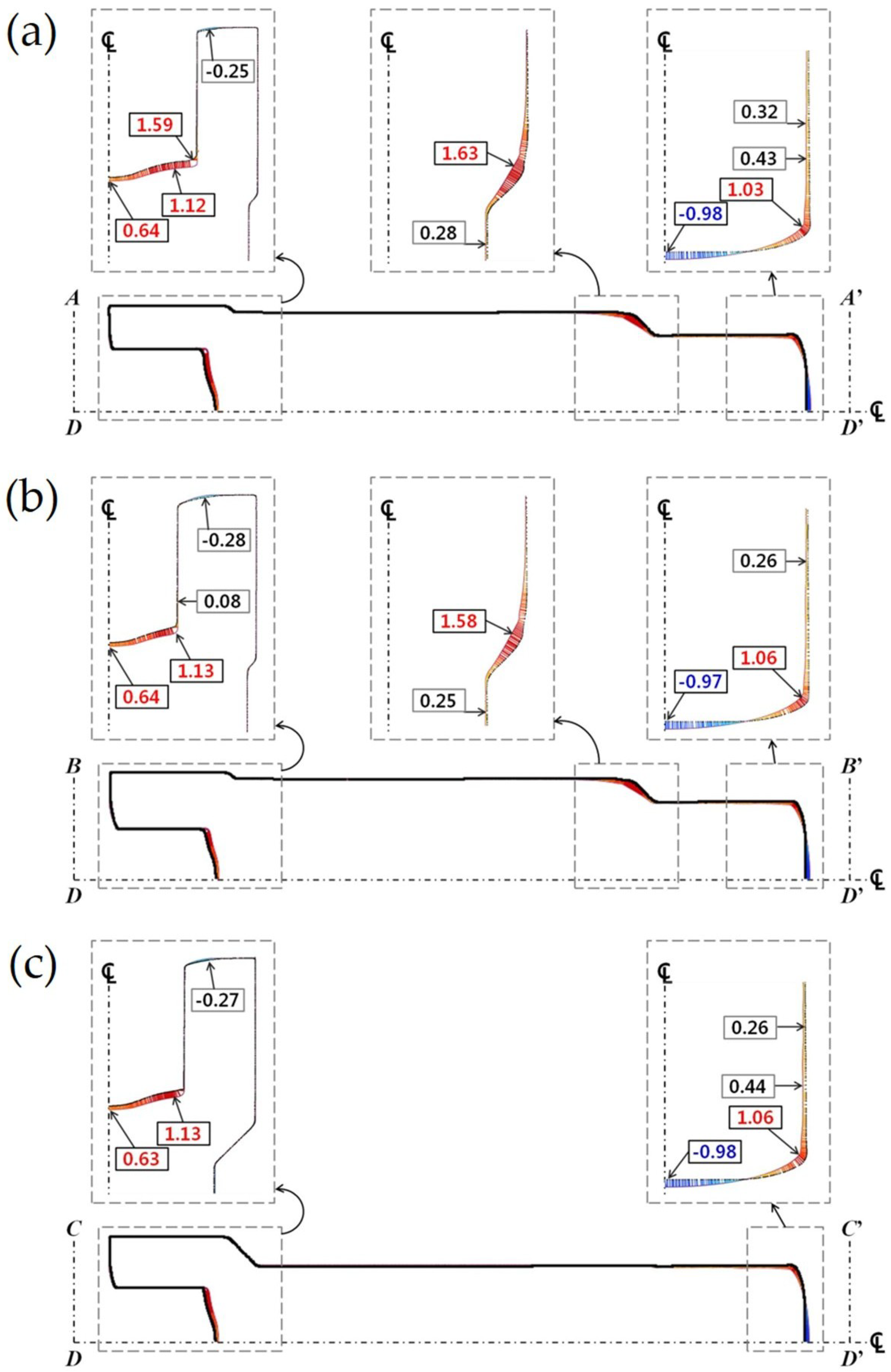
The cross-sectional configurations of the preform and the drive shaft derived from the numerical cold extrusion simulations and the 3D scanned features were compared with the required target geometries. The excessive deformations and the considerable dimensional errors were then locally observed around the tooth ends on the forward extruded spur gear region and the protruded extremity at the central area of the lower shaft, but these errors were ignored after consideration of the required dimension and its permissible error. Consequently, it was verified that the dimensional variations of the preform and the drive shaft satisfied each other well.
(4)
Finally, it was ensured that the two-stage cold forging process, which was composed of the preform operation and the forward-backward extrusion, can be successfully applied for producing the drive shaft with an irregular hexadecagonal deep groove and sixteen-tooth spur gear geometries.

Funding

This work was supported by the Basic Science Research Program (NRF-2017R1D1A1B03032741) and the Engineering Research Center Program (NRF-2012R1A5A1048294) through the National Research Foundation of Korea (NRF) grant funded by the Korea Government.

Conflicts of Interest

The author declares no conflict of interest.

References

  1. Zhang, Q.; Ben, N.Y.; Yang, K. Effect of Variational Friction and Elastic Deformation of Die on Oscillating Cold Forging for Spline Shaft. J. Mater. Process. Technol. 2017, 244, 166–177. [Google Scholar] [CrossRef]
  2. Chitkara, N.R.; Kim, Y.J. Near-Net Shape Forging of a Crown Gear: Some Experimental Results and Analysis. Int. J. Mach. Tools Manuf. 2001, 41, 325–346. [Google Scholar] [CrossRef]
  3. Jung, S.Y.; Kang, M.C.; Kim, C.; Kim, C.H.; Chang, Y.J.; Han, S.M. A Study on the Extrusion by a Two-Step Process for Manufacturing Helical Gear. Int. J. Adv. Manuf. Technol. 2009, 41, 684–693. [Google Scholar] [CrossRef]
  4. Kamouneh, A.; Ni, J.; Stephenson, D.; Vriesen, R. Investigation of Work Hardening of Flat-Rolled Helical-Involute Gears through Grain-Flow Analysis, FE-Modeling, and Strain Signature. Int. J. Mach. Tools Manuf. 2007, 47, 1285–1291. [Google Scholar] [CrossRef]
  5. Kim, S.Y.; Kubota, S.; Yamanaka, M. Application of CAE in Cold Forging and Heat Treatment Processes for Manufacturing of Precision Helical Gear Part. J. Mater. Process. Technol. 2008, 201, 25–31. [Google Scholar] [CrossRef]
  6. Maeno, T.; Mori, K.; Ichikawa, Y.; Sugawara, M. Use of Liquid Lubricant for Backward Extrusion of Cup with Internal Spline using Pulsating Motion. J. Mater. Process. Technol. 2017, 244, 273–281. [Google Scholar] [CrossRef]
  7. Ku, T.W.; Kim, L.H.; Kang, B.S. Process Simplification of Multi-Stage Forging for the Outer Race of a CV Joint. Mater. Manuf. Process. 2014, 29, 85–92. [Google Scholar] [CrossRef]
  8. Ku, T.W.; Kim, L.H.; Kang, B.S. Multi-Stage Cold Forging and Experimental Investigation for the Outer Race of Constant Velocity Joints. Mater. Des. 2013, 49, 368–385. [Google Scholar] [CrossRef]
  9. Lee, D.J.; Kim, D.J.; Kim, B.M. New Processes to Prevent a Flow Defect in the Combined Forward-Backward Cold Extrusion on a Piston-Pin. J. Mater. Process. Technol. 2013, 139, 422–427. [Google Scholar] [CrossRef]
  10. Schrader, T.; Shirgaokar, M.; Altan, T. A Critical Evaluation of the Double Cup Extrusion Test for Selection of Cold Forging Lubricants. J. Mater. Process. Technol. 2007, 189, 36–44. [Google Scholar] [CrossRef]
  11. Ku, T.W.; Kang, B.S. Tool Design and Experimental Verification for Multi-Stage Cold Forging Process of the Outer Race. Int. J. Precis. Eng. Manuf. 2014, 15, 1995–2004. [Google Scholar] [CrossRef]
  12. Matsumoto, R.; Hayashi, K.; Utsunomiya, H. Experimental and Numerical Analysis of Friction in High Aspect Ratio Combined Forward-Backward Extrusion with Retreat and Advanced Pulse Ram Motion on a Servo Press. J. Mater. Process. Technol. 2014, 214, 936–944. [Google Scholar] [CrossRef]
  13. Ku, T.W.; Kang, B.S. Tool Design for Inner Race Cold Forging with Skew-Type Cross Ball Grooves. J. Mater. Process. Technol. 2014, 214, 1482–1502. [Google Scholar] [CrossRef]
  14. Ku, T.W.; Kang, B.S. Hardness-Controlled Tool Fabrication and Application to Cold Forging of Inner Race with Skewed Ball Grooves. Int. J. Adv. Manuf. Technol. 2014, 74, 1337–1354. [Google Scholar] [CrossRef]
  15. Miyachika, K.; Katanuma, H.; Iwanaga, J.; Mada, H. Hardened Layer and Bending Fatigue Strength of Induction Hardened Thermally Refined Steel Gears. J. Adv. Mech. Des. Syst. Manuf. 2009, 3, 136–145. [Google Scholar] [CrossRef] [Green Version]
  16. Knust, J.; Podszus, F.; Stonis, M.; Behrens, B.A.; Overmeyer, L.; Ullmann, G. Preform Optimization for Hot Forging Processes using Genetic Algorithms. Int. J. Adv. Manuf. Technol. 2017, 89, 1623–1634. [Google Scholar] [CrossRef]
  17. Sedighi, M.; Tokmechi, S. A New Approach to Preform Design in Forging Process of Complex Parts. J. Mater. Process. Technol. 2008, 197, 314–324. [Google Scholar] [CrossRef]
  18. Yang, C.C.; Liu, C.L. Improvement of the Mechanical Properties of 1022 Carbon Steel Coil by using the Taguchi Method to Optimize Spheroidized Annealing Conditions. Materials 2016, 9, 693. [Google Scholar] [CrossRef] [PubMed]
Figure 1. Schematic illustrations of drive shaft with internal spline and spur gear geometries (unit: mm): (a) Three-dimensional configuration and detail dimensions; (b) Process design flow and operation procedures of two-stage cold forging.
Metals 08 00953 g001
Figure 2. Microstructural changes (X500) of AISI 1035 cold drawn carbon steel by spheroidizing annealing at 760 °C for eight hours: (a) Microstructure before spheroidizing annealing (average grain size: 8.84 μm); (b) Microstructure after spheroidizing annealing (average grain size: 9.36 μm).
Metals 08 00953 g002
Figure 3. Stress-strain curves of AISI 1035 medium carbon steel as a cold drawn round workpiece before and after spheroidizing annealing: (a) Tensile stress-strain curves; (b) Compressive stress-strain curves.
Metals 08 00953 g003
Figure 4. Geometric illustrations of tooth profile and overlapped cross-sections of drive shaft (unit: mm): (a) Tooth geometries of spur gear; (b) Overlapped cross-sections.
Metals 08 00953 g004
Figure 5. FE models applied to two-stage cold forging for producing the drive shaft: (a) FE model for preform forging; (b) FE model for forward-backward extrusion.
Metals 08 00953 g005
Figure 6. Effective stress and strain distributions obtained from forward extrusion simulation for preform forging: (a) Symmetric condition and initial mesh structure with 257,678 tetrahedral elements for preform forging; (b) Effective stress and strain distribution at punch stroke of about 53%; (c) Effective stress and strain distribution at punch stroke of 100%.
Metals 08 00953 g006
Figure 7. Re-constructed mesh structure of preform for forward-backward extrusion simulation (unit: mm): (a) Mesh structure of preform obtained by forward extrusion simulation; (b) Re-arranged mesh structure of preform for forward-backward extrusion.
Metals 08 00953 g007
Figure 8. Effective stress and strain distributions obtained from forward-backward extrusion simulation: (a) Effective stress distribution with punch strokes of 30%, 65%, and 100%; (b) Effective strain distribution with punch strokes of 30%, 65%, and 100%; (c) Top and bottom views with punch stroke of 100%.
Metals 08 00953 g008
Figure 9. Load prediction of two-stage cold forging sequence for fabricating the drive shaft.
Metals 08 00953 g009
Figure 10. Preform fabricated by forward extrusion and drive shaft produced by forward-backward extrusion: (a) Preform and 3D scanned image; (b) Drive shaft and 3D scanned image.
Metals 08 00953 g010
Figure 11. Dimensional suitability of forward extruded preform on OP-O’P’ cross-sectional plane (unit: mm): (a) Comparison of dimensional suitability between 3D scanned image and designed preform; (b) Comparison of dimensional suitability between simulated layout and designed preform; (c) Comparison of dimensional suitability between 3D scanned image and simulated layout.
Metals 08 00953 g011
Figure 12. Dimensional variation between 3D scanned image and target shape of the drive shaft (unit: mm): (a) Shape comparison on DA-DA cross-sectional plane (top land direction); (b) Shape comparison on DB-DB cross-sectional plane (top land direction); (c) Shape comparison on DC-DC cross-sectional plane (bottom land direction).
Metals 08 00953 g012
Figure 13. Dimensional variation between simulated layout and target shape of the drive shaft (unit: mm): (a) Shape comparison on DA-DA cross-sectional plane (top land direction); (b) Shape comparison on DB-DB cross-sectional plane (top land direction); (c) Shape comparison on DC-DC cross-sectional plane (bottom land direction).
Metals 08 00953 g013
Figure 14. Dimensional variation between simulated layout and 3D scanned image of the drive shaft (unit: mm): (a) Shape comparison on DA-DA cross-sectional plane (top land direction); (b) Shape comparison on DB-DB cross-sectional plane (top land direction); (c) Shape comparison on DC-DC cross-sectional plane (bottom land direction).
Metals 08 00953 g014
Table 1. Chemical composition of AISI 1035 carbon steel material.
ElementCMnSiPSFe
wt%0.3500.8000.2750.0030.005Bal.
Table 2. Mechanical properties of AISI 1035 medium carbon steel as a cold drawn round specimen.
Tensile PropertiesRaw MaterialAnnealed Material
Young’s Modulus (GPa)196196
Yield Strength (MPa)410350
Ultimate Strength (MPa)755643
Poisson’s Ratio0.290.29
Fracture Strain0.282140.32096
Table 3. Dimensional accuracy required for preform and drive shaft (unit: mm).
Geometric FeatureRequired DimensionPermissible ReferenceDimensional Value
PredictedMeasured
PreformUpper HeadOuter DiameterΦ51.0±0.250.000.02
Length96.0±1.000.28−0.65
Lower ShaftOuter DiameterΦ36.7±0.25−0.02−0.03
Length33.5±1.500.071.04
Drive ShaftUpper HeadOuter DiameterΦ51.6±0.250.01−0.04
Length36.5±1.50−0.01−0.25
Groove Depth22.7−0.20~1.501.28−0.13
Spur GearFace Width92.0±1.50−0.65−0.49
Tooth Height5.9±0.250.000.12
Root DiameterΦ37.1±0.250.000.00
Lower ShaftOuter DiameterΦ36.7±0.25−0.010.24
Length35.0±1.50−2.05−1.05

