Article

Experimental and Numerical Study on the Lateral-Torsional Buckling of Steel C-Beams with Variable Cross-Section

1
Department of Civil Engineering, University of Salerno, 84084 Fisciano (Salerno), Italy
2
Department of Structures for Engineering and Architecture, University of Naples Federico II, 80125 Naples, Italy
3
Department of Civil, Building and Environmental Engineering, University of Naples Federico II, 80125 Naples, Italy
*
Authors to whom correspondence should be addressed.
Metals 2018, 8(11), 941; https://doi.org/10.3390/met8110941
Submission received: 15 October 2018 / Revised: 26 October 2018 / Accepted: 9 November 2018 / Published: 13 November 2018

Abstract

:
Metallic thin-walled beams with continuously varying cross-sections loaded in compression are particularly sensitive to instability problems due to lateral-torsional buckling. Such a phenomenon depends on several parameters, including the cross-sectional properties along the entire length, material properties, load distribution, support, and restraint conditions. Due to the difficulty of obtaining analytic solutions for the problem under consideration, the present study takes a numerical approach based on a variational formulation of the lateral-torsional buckling problem of tapered C-beams. Numerical simulations are compared with experimental results on the buckling of a physical model of at thin-walled beam with uniformly varying cross-section, with the aim of assessing the accuracy of the proposed approach. The good agreement between numerical and experimental results and the reduced computational effort highlight that the proposed variational approach is a powerful tool, provided that the geometry of the structure and the boundary conditions are accurately modeled.

1. Introduction

Lateral-torsional buckling of thin-walled beams of variable, open cross-sections is a topic of key importance to structural, mechanical, and aeronautical engineering. By removing a suitable portion of material in a proper portion of the beam, one can increase its stability, by contemporarily ensuring the economic convenience of the design. Nonetheless, a slender thin-walled beam with open and variable cross-section loaded in compression may suddenly buckle by twisting, or in a combined mode of twisting and bending. This is explained by the shear center position’s dependence on the applied load and cross-section geometry (see [1] and references therein), as well as the low torsional stiffness of open thin-walled sections. Past and recent history is full of memorable examples of structural collapse events due to lateral-torsional buckling, especially during the construction phase of bridges or trusses, when proper lateral and torsional braces are either absent or partially in place. Refer, e.g., to the following collapse events: Pedestrian Marcy footbridge in New York (2002), Pedestrian River Road-Avonside Drive bridge in Christchurch (2010), and the 102nd Avenue Bridge in Edmonton (2015), to cite just a few examples. The above comments explain why the topic of lateral-torsional buckling has been recognized for many years and is still an active area of research. Lateral-torsional buckling theory is covered extensively in text books ([2,3,4,5]) and a considerably large number of analytical and experimental research articles have been published on this topic. Noticeable contributions have been provided by Eishakoff, with reference to the response of variable cross-section beams ([6]); El-Mahdy, for what concerns the inelastic lateral-torsional buckling of singly symmetric I-beams with variable flange ratio ([7]); and Scott, regarding an experimental investigation on the natural frequencies and mode shapes of tapered C-beams ([8]). Several approaches can be employed for solving the stability problem of C-beams with variable cross-section. The ‘Bifurcation Approach’, introduced by Koiter ([9]), is the oldest method available in the literature; it reduces the stability analysis to an eigen-boundary-value problem. Another method, known as the ‘Dynamic Approach’, introduces a slight perturbation in the equations that govern the small free vibrations of the elastic beam; if a disturbance causes a finite deviation of the beam from its equilibrium state, then a critical state is reached ([10]). The ‘Energy Method’ assumes the action of conservative forces and defines the equilibrium as stable if the total potential energy is at a stationary point ([1,11,12,13,14,15,16]). Such a method is suitable for hand use and provides numerical solutions that are sufficiently accurate for technical purposes, leading to an upper bound estimate of the true buckling load. Complex problems that require high computational effort can be addressed by the finite element method that produces very accurate results, but may overestimate the critical load in the case of thick beams ([17,18,19,20,21,22,23]). Finally, the ‘Imperfection Method’ allows the inclusion of effects due to initial imperfections in loading conditions and beam geometry ([24,25]).
This paper presents numerical and experimental results on the lateral-torsional buckling behavior of a C-beam featuring a uniformly varying cross-section made of S420-grade structural steel. An experimental test is conducted by loading in compression a physical model of a metallic beam with uniformly varying C-section, which is suitably connected to the grips of a universal testing machine. The tested beam is fully instrumented with displacement transducers and strain gauges, and is loaded in compression up to lateral-torsional buckling, and in the post-buckling regime. Numerical estimates of the buckling load are obtained through a variationally informed discretization procedure, for two different models of the boundary conditions of the beam. The main goal of the presented study is to experimentally assess the accuracy of the proposed numerical approach to the buckling load of tapered C-beams, which is of great technical relevance, due to the peculiar complexity of the underlying mathematical problem. The outline of the paper is as follows. Section 2 introduces the employed physical model and presents basic concepts of lateral-torsional stability. Next, the same section introduces the variational method and the discretization procedure employed to develop numerical approximations. Section 3 presents numerical and experimental results dealing with the lateral-torsional buckling of the investigated beam. A comparison between numerical and experimental results is carried out in Section 4. The concluding remarks presented in Section 5 highlight good agreement between numerical and experimental results, provided that the boundary conditions of the analyzed beam are correctly modeled, and an appropriate class of kinematically admissible configurations is introduced as search space of the numerical approximation procedure.

2. Materials and Methods

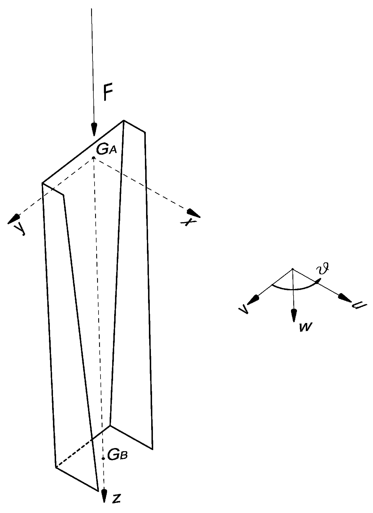
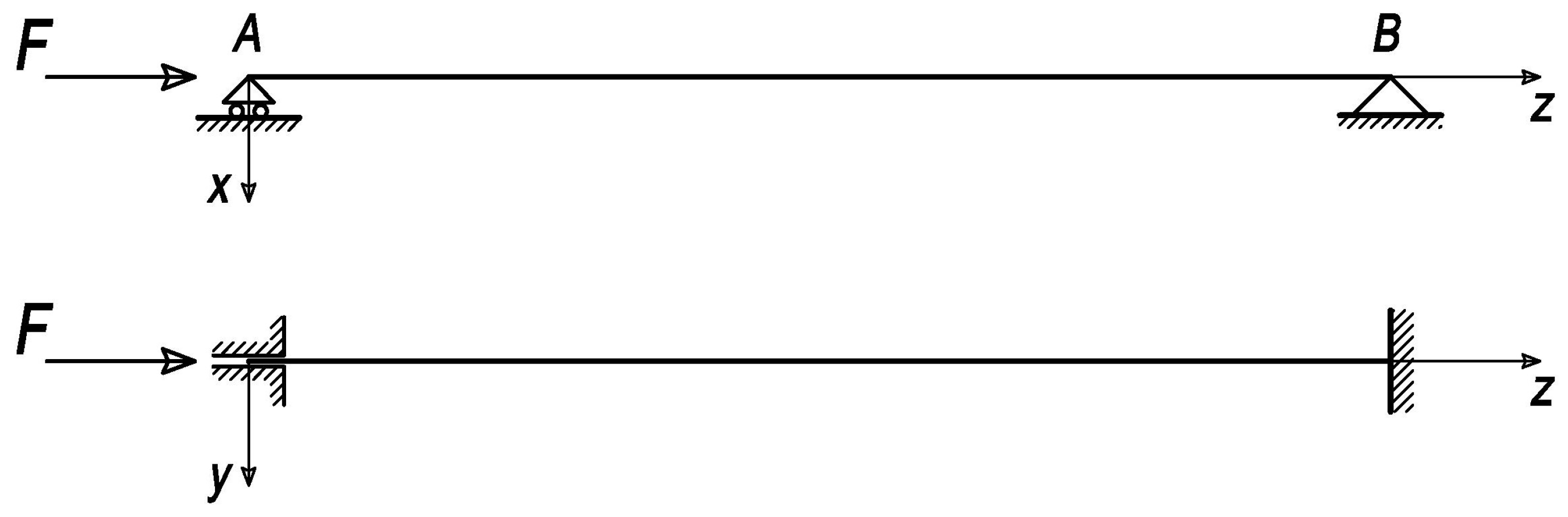
2.1. Beam Model and Basic Assumptions

We investigate lateral-torsional buckling of a simply supported thin-walled beam, which gradually changes its cross-section along the length. We focus our attention on a mono-symmetric C-beam with linearly variable height and width but constant thickness δ = 3 mm and invariant principal axes of inertia. Table 1 reports end cross-sections (labeled A and B) properties of the analyzed model, by letting x c denote the horizontal distance from the shear center to web middle line, H denote the width between centers of flanges, B denote the distance from web middle line to flange-end, and A denote the cross-section area. The examined load condition consists of an axial compressive force N = F applied at beam end centroid G A (Figure 1). The beam, having a length of = 900 mm, is made of S 420 structural steel. Table 2 reports beam mechanical properties: Young modulus E, shear modulus G and yield strength f y . A right-hand orthogonal coordinate system G x y z is introduced, where z denotes the undeformed longitudinal axis of the beam and x and y the principal bending axes. The origin of these axes is located at the center G A (Figure 1). The shear centers of the end cross sections are denoted C A and C B , respectively.
Let u, v and w denote the displacements of the cross-section centroid in the x, y and z directions; and ϑ the angle of twist. In a first modeling of the boundary conditions of the beam, the end rotations around the z axis (torsional or twisting rotations), the end rotations about the x axis (out-of-plane flexural rotations), and the cross-section warping are prevented ( ϑ = ϑ = 0 ), while flexural rotations around the y axis (in-plane flexural rotations) are not constrained. Such a modeling assumes the presence of a movable cylindrical hinge at section A, which allows translations along the beam’s axis z, and a fixed cylindrical hinge at section B, which prevents the translations along the x, y and z axes (cylindrical hinge boundary conditions, cf. Figure 2). A second modeling instead assumes zero (both in-plane and out-of-plane) flexural rotations and zero torsional rotations at both ends of the beam (clamped boundary conditions).
The adopted mechanical model employs the following main assumptions:
  • small displacement, i.e., linearized kinematics;
  • Vlasov’s assumptions of negligible shear deformation on the middle surface, and perfect rigidity of the cross sections in their own planes;
  • conservative forces and elastic behavior;
  • pre-critical strains are infinitesimal;
  • dynamic effects are negligibly small;
  • body forces are absent;
  • isotropic, homogeneous, and linear elastic material;
  • shear and rotation centers coincide;
  • the shear centers of the cross-sections lie on an axis that remains straight during deformation.

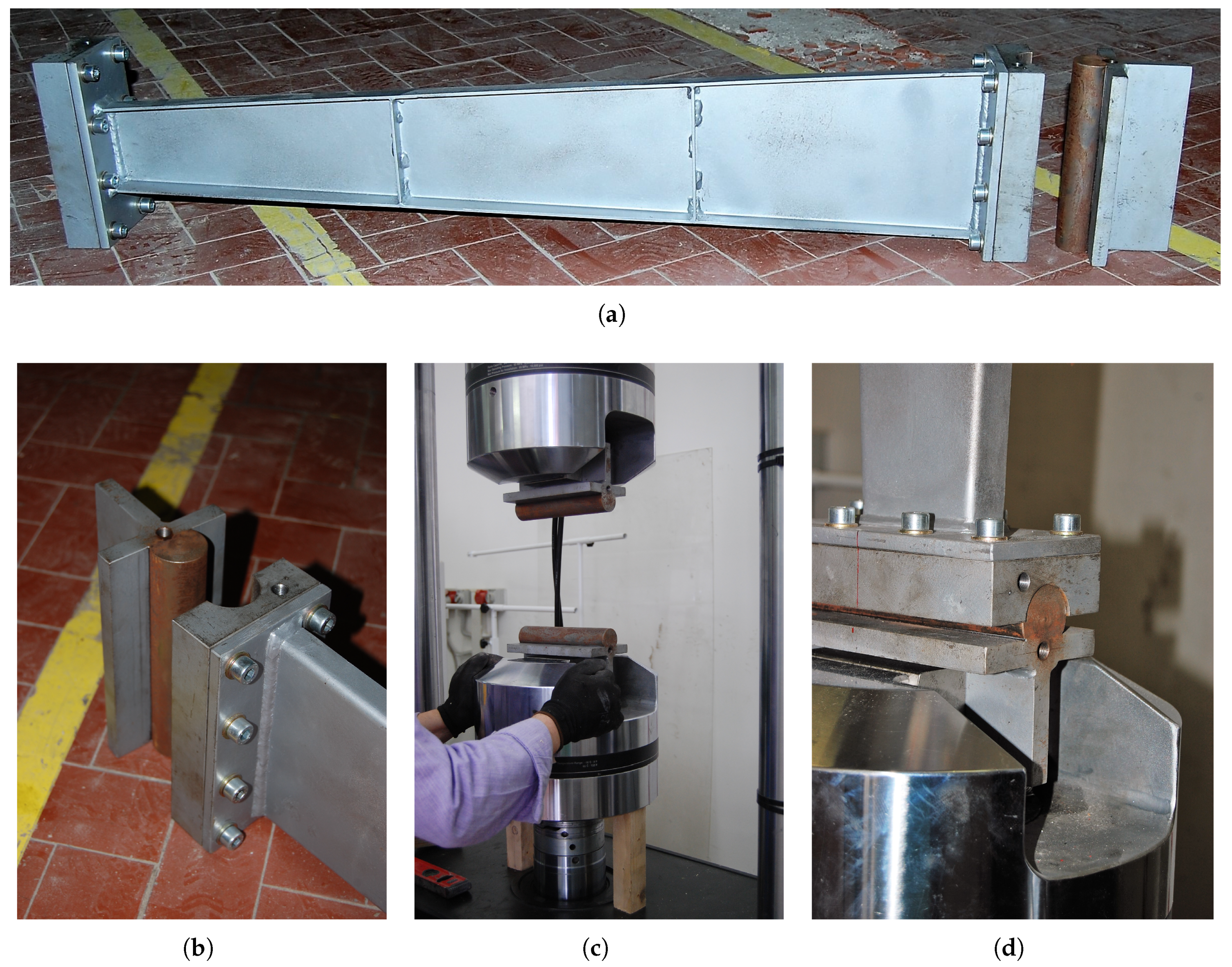
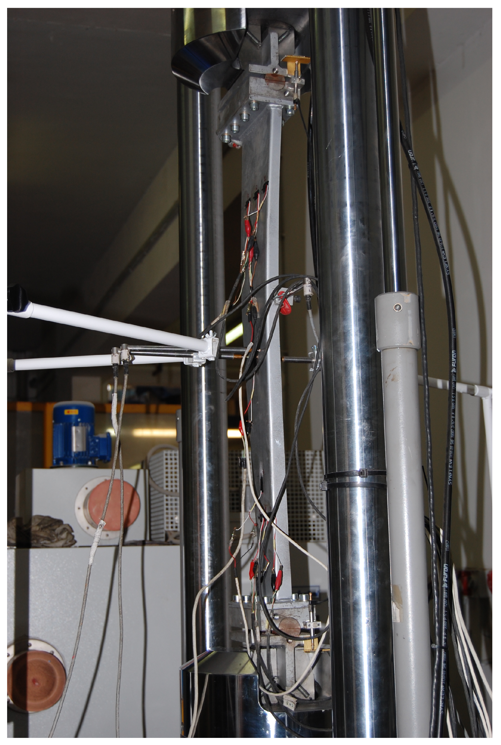
2.2. Experimental Program

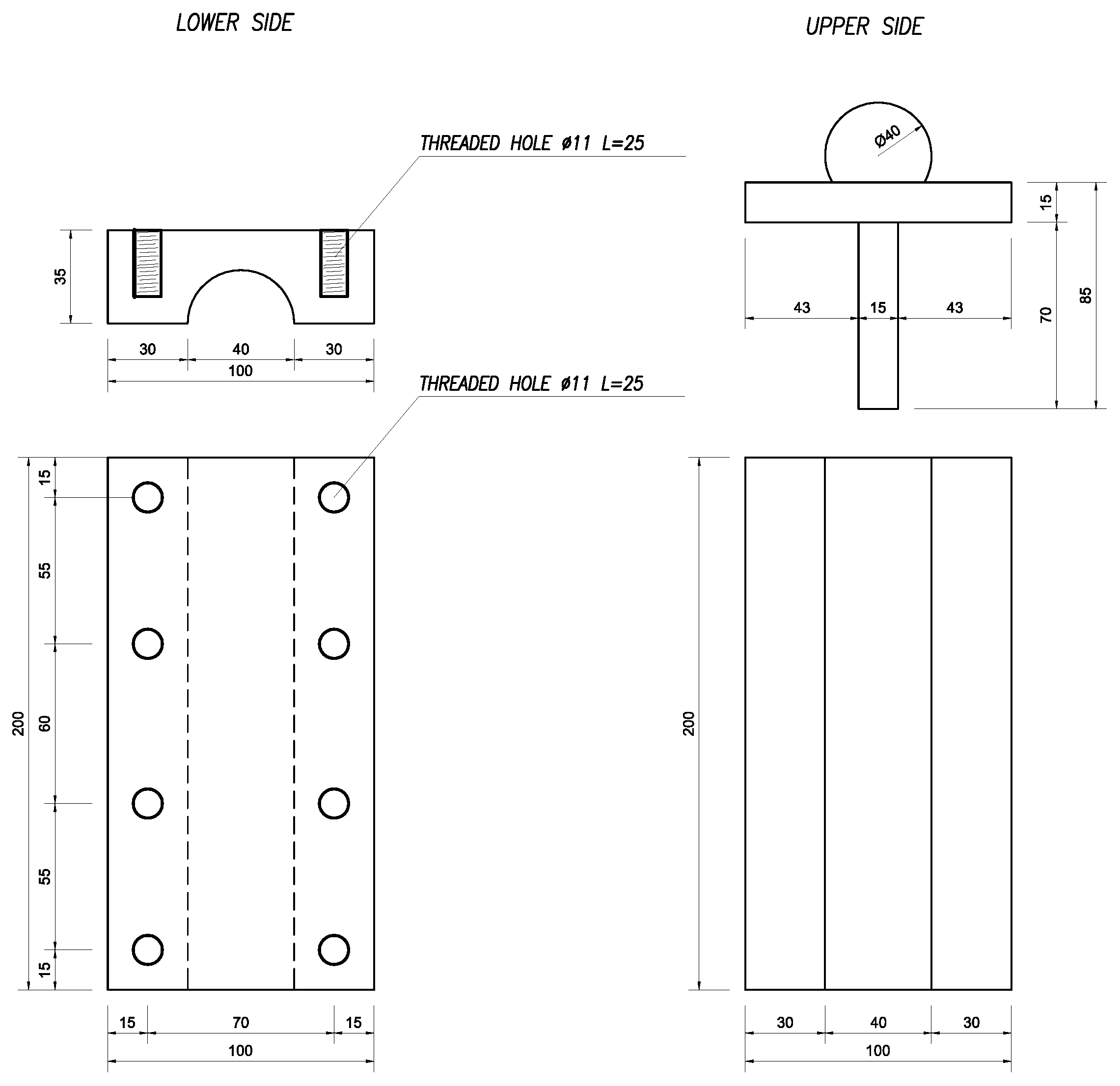
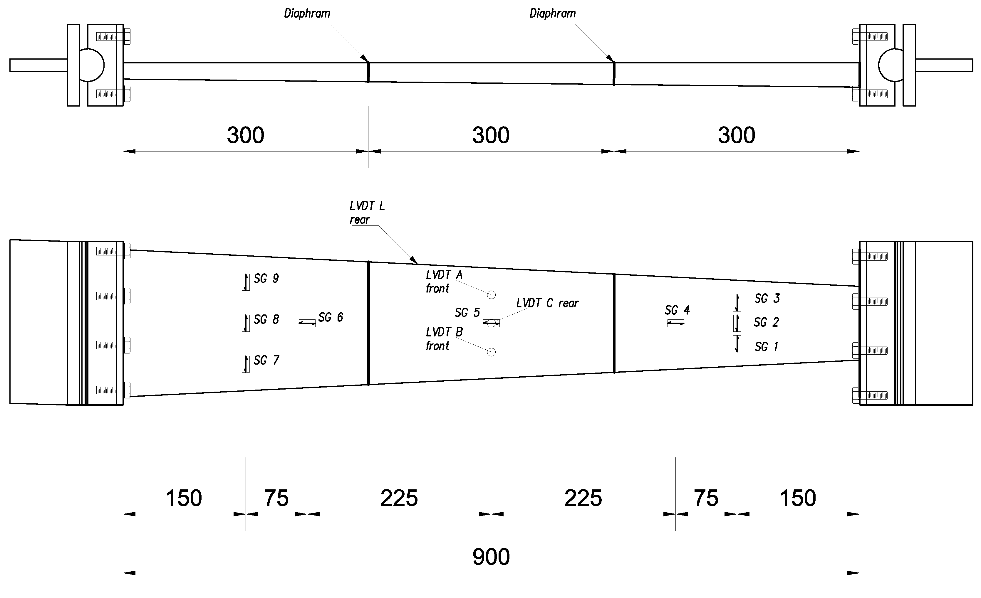
2.2.1. Design of Specimen and Test Setup

We performed a quasi-static compression test on a physical model of the analyzed beam at the material test laboratory ”Adriano Galli” of the Department of Structures for Engineering and Architecture of the University of Naples Federico II.
The tested sample was mounted on a M T S 810 universal testing machine (Italsigma s.r.l., Forlì, Italy), equipped with 550 kN load cell, employing displacement control with loading rate of 5 Hz. The sample was beveled and produced press-bending a sheet metal in S 420 steel-grade (Table 2). As shown in Figure 3 and Figure 4, each cylindrical hinge is made up of two parts: the upper one, which represents the portion to be gripped, is made up of two 20 cm long and 15 mm thick steel blades, welded orthogonally to each other at the center line; the vertical blade is clamped directly to the operating machine. Below the horizontal slab is welded a 20 cm long steel cylinder (male) with a 20 mm radius. This represents the real hinge constraint.
The lower part of the constraint is made up of a 35 mm thick steel blade, 20 cm long and with a cylindrical hole at the centers line (female) 20 mm deep, which houses the male of the upper part. Beam web is welded to a shear tab bolted on the steel blade using eight M 10 class 8.8 bolts with nuts and washers. This steel plate is made with the 8 mm thick steel plate ( S 420 ). The hinges are made of Ni-Cr hardened steel with yield stress of 900 MPa and failure stress of 2400 MPa. The hinges technical details were consistent with the prescriptions of UNI-CNR 10018 (case of linear contact limit, through the Hertz formulas for cylindrical surfaces [26]). The beam is equipped with two elastic transverse plates (diaphragms) placed at z = 300 mm and z = 600 mm from the initial section A. Such plates are made of S 420 -grade structural steel with thickness of 3 mm (Figure 4a).

2.2.2. Instrumentation

The analyzed beam sample was equipped with displacement transducers of the WA-type series and uniaxial electrical resistance strain gauges ( 10 mm long) for general stress measurement along the 0 and 90 directions on both sides of the beams, as shown in Figure 5. Lateral and distortional deflections of the steel beam was measured by means of four Linear Variable Differential Transducers (LVDTs) along the beam length. As depicted in Figure 5, three of them (labeled LVDT A–C) were mounted, horizontally, to the front and rear web at mid-span of the beam, to capture its lateral deflection. The last transverse LVDT (LVDT L) was placed, horizontally, on the top flange, to capture distortional buckling mode in addition to the flexural-torsional mode.
The sample test was stopped after the strain reached the plastic region to inspect the subcritical, critical, and post-critical behaviors of the beam.

2.3. Theoretical Framework

2.3.1. Shear Center Position

For a beam with a variable single symmetric cross-section with z as symmetry axis, the shear center will be located along the z-axis ( y c = 0), but its position depends both on the geometry of the cross-section, and the applied stress [1], according to the following equation:
x c = B 2 · H 2 · δ 4 I x + H T y · N · δ 2 A 2 · d B d z · B · δ 2 M x δ · d d z 6 B · H 6 B · H 2 + H 3 · B δ 2
where T y is the shear force in y direction and M x is the bending moment about x axis.

2.3.2. Flexural-Torsional Stability: Governing Equations

According to the Vlasov torsion theory [3] and the assumptions listed in Section 2.1, the flexural-torsional equilibrium equations for beam stability are [1]:
( E · I y · u ) + F · u F · y ^ G · ϑ = 0 ( E · I x · v ) + F · v + F · x ^ G · ϑ = 0 C ω · ϑ + C ω · ϑ W z F · I c A · ϑ W z F · I c A · ϑ F · u · y ^ G + F · v · x ^ G = 0
where: ( · ) denote the z-derivative; A , I x and I y are respectively the cross-section area and the second moments of area about the principal axes x and y; I c denotes the polar moment of area about shear center; W z and C ω are respectively St-Venant warping rigidity and warping constant; indicating by C x ^ y ^ the axes parallel to G x y with origin in the shear center C A , x ^ G and y ^ G denote centroidal coordinates in C x ^ y ^ . The components of the deflection curve in the centroidal axes direction during buckling are derived from those of the shear center as follows
u = u c ( y y c ) · ϑ v = v c + ( x x c ) · ϑ w = 0

2.3.3. Variational Approximation

Due to the variability of the cross-section, the numerical integration of differential Equation (2) would be complex and rather involved. In this paper, we make use of an energy approach to the mechanical problem formulated in the previous section, which is based on the principle of stationary potential energy [27]. It consists of a variational approximation to the critical equilibrium problem that provides an upper bound of the buckling load [28]. The stability points are associated with the stationarity of the second variation of the total potential energy
2 E = L 2 + W
where it results:
L 2 = V σ z · 2 ε z d V
and
W = 1 2 0 l E · I y · u 2 d z + 0 l E · I x · v 2 d z + 0 l M t · ϑ d z
Here, σ z is the stress component along z-axis, 2 ε z is the second-order component of the strain along z-axis, V is the volume of the beam and M t is the torque
M t = W z · ϑ C ω · ϑ
The well-known Trefftz stability criterion [29]
2 E q i = 0 i = 1 , ... , m
provides three simultaneous differential equations in m Lagrange multipliers q i = q i ( u , v , ϑ ) . Such equations are m necessary and sufficient conditions of critical equilibrium. The associated eigenvalue problem is nonlinear and provides the critical points that can be either limit points or bifurcation points.

2.4. Numerical Procedure

The total potential energy is a functional of the continuous functions u ( x ) , v ( y ) , w ( z ) . We now introduce a Rayleigh-Ritz approximation procedure that transforms the continuous problem into discrete form. Let u c , v c , w c be the displacement components of the shear center and ψ j , i the partial sum of the first n terms of the Taylor series expansion. Describing the class of kinematically admissible configurations s j = s j ( u c , v c , w c ) as linear combination of unknown coefficients q j , i the total potential energy becomes a quadratic function of the 3 m parameters
s j = i = 1 m q j , i · ψ j , i j = 1 , 2 , 3
Such an approach leads us to describe the deformed shape of the beam as the summation of m natural modes. Substituting Equation (9) into the functional (4) and enforcing the stationary conditions (8), we obtain a characteristic equation that determines approximations F i of the buckling load. Such quantities are upper bounds of the exact eigenvalues of the continuous problem, whose accuracy increases with the number of the adopted Lagrangian parameters q j , i [28].

3. Numerical and Experimental Results

3.1. Numerical Results

The present section applies the Rayleigh-Ritz discretization procedure presented in Section 2.4 to the stationarity conditions of the second variation of the total potential energy. Referring to the model pictured in Figure 2 and assuming, in first instance, cylindrical hinge boundary conditions (cf. Section 2.1), we introduce the following class of kinematically admissible configurations
u c = i = 1 n u i sin n π z ^ l v c = i = 1 n v i 1 cos 2 n π z ^ l ϑ = i = 1 n ϑ i 1 cos 2 n π z ^ l
Such coordinate functions satisfy the subsidiary kinematic boundary conditions
u ( 0 ) = u ( 0 ) = u ( l ) = u ( l ) = 0 v ( 0 ) = v ( 0 ) = v ( l ) = v ( l ) = 0 ϑ ( 0 ) = ϑ ( 0 ) = ϑ ( l ) = ϑ ( l ) = 0
where the boundary conditions on ϑ and ϑ are appropriate for zero torsional rotation and zero warping, respectively. Substituting Equation (10) into the functional (4) and imposing the stationarity conditions (8), we obtain a linear eigenvalue problem that provides approximations of the true buckling load. The best approximation of the buckling load is given by the lowest eigenvalue of the discrete problem.
Upon arresting the series expansion in Equation (10) to the first term (i.e., n = 1 ), we obtain
F 1 = 15.9 kN ; F 2 = 135.8 kN ; F 3 = 4602.2 kN .
By retaining the first two terms of the series (10) (i.e., n = 2 ) and enforcing the stationarity conditions (8), we instead obtain the following approximate eigenvalues
F 1 = 15.2 kN ; F 2 = 44.8 kN ; F 3 = 63.8 kN ; F 4 = 144.2 kN ; F 5 = 4330.1 kN ; F 6 = 15437.3 kN .
On increasing n up to 3, the solution accuracy does not improve significantly, since we get in this case
F 1 = 15.2 kN ; F 2 = 43.9 kN ; F 3 = 60.0 kN ; F 4 = 143.5 kN ; F 5 = 145.5 kN ; F 6 = 307.4 kN ; F 7 = 4587.1 kN ; F 8 = 16905.7 kN ; F 9 = 35030.1 kN .
Based on the above results, we conclude that a numerical approximation to the buckling load of the beam under consideration is F c r , n u m = 15.2 kN.
The mechanical model considered so far assumes the presence of cylindrical hinges at both ends of the beam. In real life, due to friction issues and not the non-smooth nature of the hinge-beam interfaces, the actual boundary conditions are intermediate between those corresponding to hinged and fixed supports. By re-running the numerical approximation scheme presented above on assuming the following class of admissible configurations
u c = i = 1 n u i 1 cos 2 n π z ^ l v c = i = 1 n v i 1 cos 2 n π z ^ l ϑ = i = 1 n ϑ i 1 cos 2 n π z ^ l
that satisfy the following (perfectly sampled) boundary conditions
u ( 0 ) = u ( 0 ) = u ( l ) = u ( l ) = 0 v ( 0 ) = v ( 0 ) = v ( l ) = v ( l ) = 0 ϑ ( 0 ) = ϑ ( 0 ) = ϑ ( l ) = ϑ ( l ) = 0
for n = 3 we obtain
F 1 = 63.2 kN ; F 2 = 136.1 kN ; F 3 = 253.1 kN ; F 4 = 515.6 kN ; F 5 = 570.1 kN ; F 6 = 1187.0 kN ; F 7 = 3155.5 kN ; F 8 = 18267.6 kN ; F 9 = 28469.0 kN .
It can reasonably be concluded that the lateral-torsional buckling load of the physical beam model under examination ranges in the interval F c r , n u m [ 15.2 kN , 63.2 kN ] .

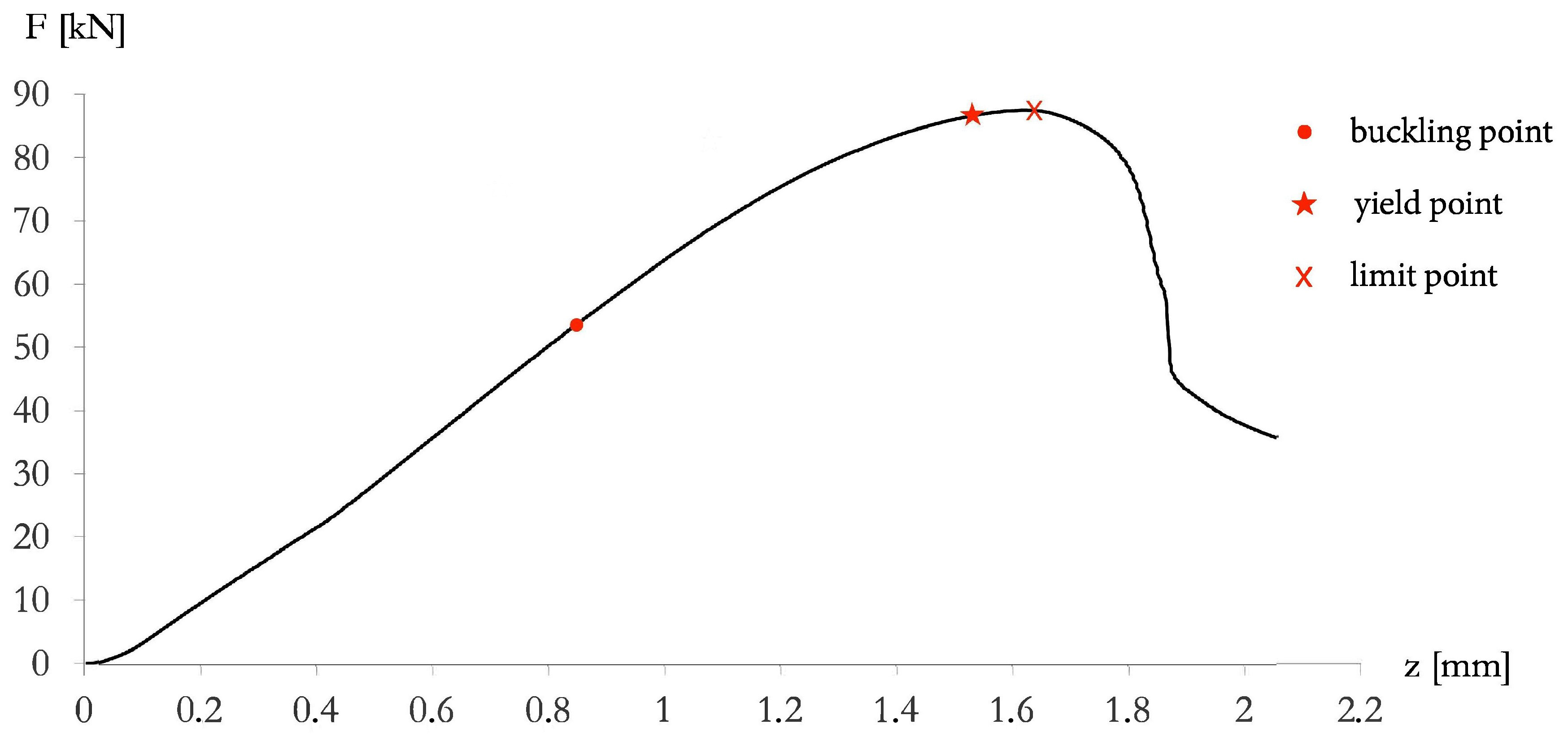
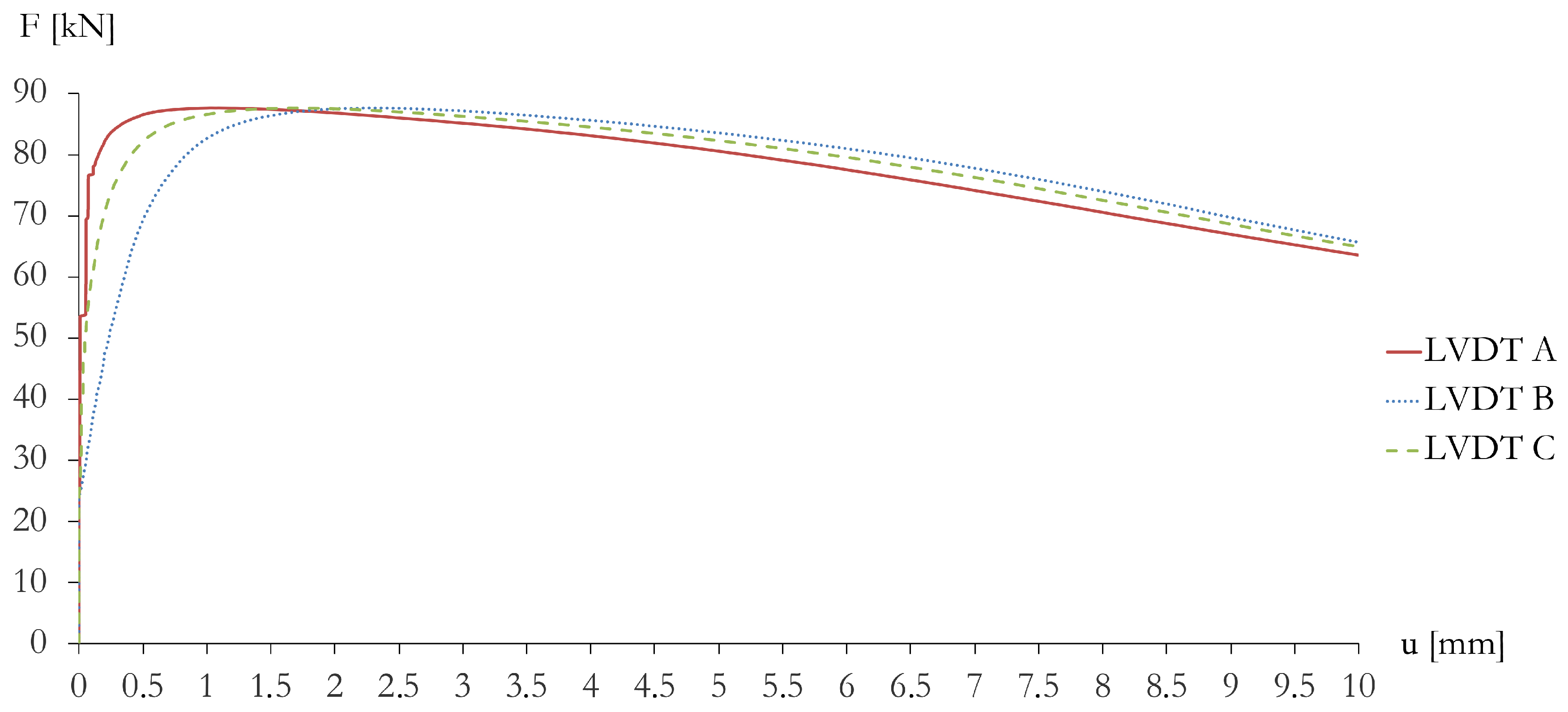
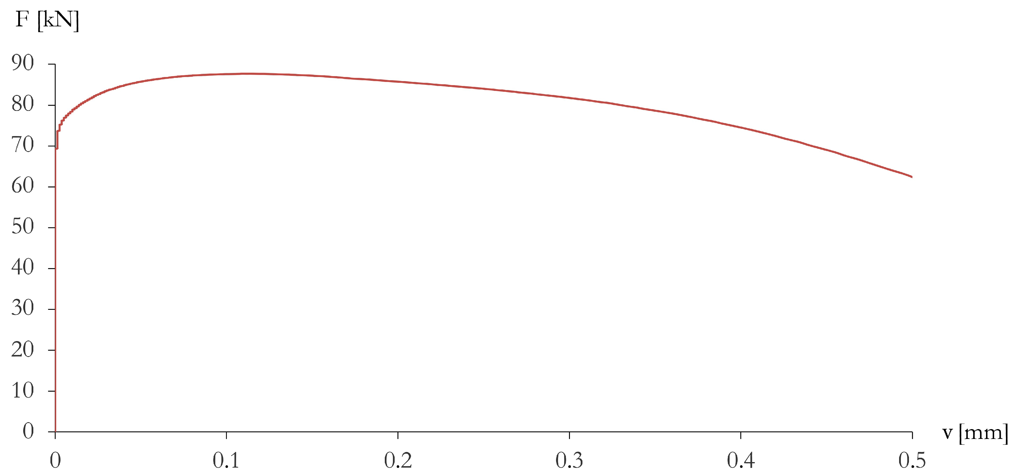
3.2. Experimental Results

Figure 6, Figure 7, Figure 8 and Figure 9 illustrate the results of the experimental test of the beam model illustrated in Section 2 and the buckled configuration of the beam. The experimental F vs. w curve (Figure 6) shows a stable pre-buckling path: the load and deformations simultaneously rise until a limit point (red cross mark “×” in Figure 6) is reached. Beyond the limit point, the tangent modulus rapidly decreases as the deformation increases with an unstable, descending, post-buckling path. The beam exhibits antisymmetric behavior, with sensitivity to geometric imperfection and load eccentricity, which is customary in coupled stability problems. The bifurcation point degenerates into a limit point with an Erosion of the Critical Bifurcation Load (ECBL) due both to the imperfections and to the effect of interaction between the purely bending mode and the bending-twisting mode ([30]). We identify the experimental buckling load with the first inflection point of the experimental F vs. w curve at F c r , e x p = 53.6 kN (red circle mark ‘’ in Figure 6). The beam buckles when it is still in the elastic range so that the beam failure is governed by geometric, rather than material, non-linearity. The tested beam reaches the yield strength F y = 86.7 kN (red star mark ‘’ in Figure 6) when the vertical displacement reaches the value of 1.5 mm. Such a yielding point was detected from the strain gauge readings. The experimental results highlighted a second, distortional buckling event (local-torsional mode), taking place after the occurrence of the flexural-torsional buckling mode, for F = 69.4 kN. Such a second buckling phenomenon caused the flange to start rotating about the flange/web junction (cf. Figure 8).

4. Discussion

The experimental response of the tested beam under uniaxial compression loading (in displacement control) reveals that a global, flexural-torsional buckling event takes place before the occurrence of local buckling at the flange/web junctions. Generally, during the compression of thin-walled beams that are not reinforced by transverse braces and/or diaphragms, the flange, and/or the web buckle locally over short distances without overall lateral-torsional deflections of the beam. In the performed test, the specimen was strengthened with two diaphragms (Section 2.2.1), which induced concentrated longitudinal ‘bimoments’ in the cross-sections strengthened by such elements [1]. The concentrated bimoments are proportional to the relative warping of the beam in the sections of interest, and to the mechanical and geometrical properties of the stiffening plates. The diaphragms proved to affect the state of stress of the structure, partially preventing local warping, and significantly improving the resistance of the beam to local stability phenomena. A good agreement between the experimental buckling load ( F c r , e x p 54 kN) and the numerical predictions of such a quantity ( F c r , n u m [ 15.2 kN, 63.2 kN]) is observed in the case of semi-rigid boundary conditions ( F c r , n u m 60 kN). It is worth remarking that the adopted numerical method produces upper bounds of the exact buckling load [28]. Such boundary conditions ostensibly better approximate the actual support conditions of the beam under examination, due to not-negligible friction forces at the interfaces between the terminal cylindrical hinges and the end cross-sections of the beam.
It is worth remarking that the experimental results examined in this work highlight a noticeable imperfection sensitivity of the tested beam, as it is noted from the F vs. u plots shown in Figure 7, which vary from one LVDT to another because of the occurrence of pre-buckling twisting rotations of the beam (cf. [31]). Interestingly, we observe a similarity between the warping deformation exhibited by the beam studied in the present work and that predicted by the finite element simulations presented in Figure 4b of [32] for tapered I-beams with similar aspect ratios. Finally, the localization of the buckling zone towards the top of the beam (cf. Figure 9) confirms the torsional nature of such a phenomenon, since the torsional vs. Eulerian buckling load ratio gets lower when one makes use of the cross-sectional properties of the top section, instead of the cross-sectional properties of the bottom section (cf. Timoshenko [2]). Overall, we wish to emphasize that the experimentally determined force vs. deflection curves reveal an antisymmetric buckling mode of the tested beam. The experimental results also highlight the influence of the stiffening plates on the buckling response of the beam. Such elements indeed retard local buckling at the flange/web junctions and let global buckling to anticipate local buckling.

5. Concluding Remarks

We have investigated the stability problem of thin-walled open-section columns with mono-symmetric C-cross-section uniformly varying along the length. Approximate solutions to the lateral-torsional buckling problem of such structures were developed through a variational procedure employing the Trefftz stability method, and the Rayleigh-Ritz discretization technique (cf. Section 2.4). An experimental investigation was carried out on a physical model, with the aim of inspecting the accuracy of numerical predictions of the buckling load deriving from such a numerical approximation procedure (Section 3.2). A good agreement between numerical predictions and experimental results was recorded when we modeled the end supports as semi-rigid joints. Marked deviations between numerical and experimental results were instead observed in presence of a modeling of the beam with cylindrical hinges at both ends. The above observations lead us to conclude that the appropriate modeling of boundary conditions, and an accurate formulation the search space of the discrete approximation procedure are key factors to obtain accurate estimates of the buckling load of C-beams with non-uniform cross-section (cf. Section 3.1).
Future extensions of the present research will include a broader experimental campaign on the lateral-torsional buckling of thin-walled beams with variable cross-sections, both reinforced and not reinforced by transverse plates along the span. Special attention will be devoted to further understand the effects of stiffening diaphragms on the lateral-torsional behavior of thin-walled metallic beams. Additional future research will be devoted to extending the mechanical model presented in this work, to account for an accurate description of post-yielding phenomena, and geometrical imperfections.

Author Contributions

Conceptualization, I.M.; methodology, I.M., M.M.; software, I.M.; validation, I.M., V.P., A.F. and M.M.; formal analysis, I.M.; investigation, I.M.; resources, M.M., M.F.; data curation, I.M. and F.F.; writing—original draft preparation, I.M. and F.F.; writing—review and editing, I.M. and F.F; visualization, I.M. and F.F.; supervision, F.F.; project administration, M.M.; funding acquisition, M.M.

Funding

I.M. and F.F. acknowledge financial support from the Italian Ministry of Education, University and Research (MIUR) under the ‘Departments of Excellence’ grant L.232/2016.

Acknowledgments

I.M., M.M., M.F., V.P. gratefully acknowledge financial support from Department of Structures for Engineering and Architecture (DiSt), University of Naples Federico II, Naples, Italy. The authors wish to thank the DiSt laboratory staff for technical help and assistance with the experimental test.

Conflicts of Interest

The authors declare no conflict of interest. The funders had no role in the design of the study; in the collection, analyses, or interpretation of data; in the writing of the manuscript, or in the decision to publish the results.

References

  1. Mascolo, I.; Pasquino, M. Lateral-torsional buckling of compressed highly variable cross section beams. Curved Layer. Struct. 2016, 3, 146–153. [Google Scholar] [CrossRef]
  2. Timoshenko, S.P.; Gere, J.M. Theory of Elastic Stability; McGraw-Hill: New York, NY, USA, 1961; ISBN 9781306346726. [Google Scholar]
  3. Vlasov, V.Z. Thin-Walled Elastic Beams; National Science Foundation: Washington, DC, USA, 1984. [Google Scholar]
  4. Simitses, G.J.; Hodges, D.H. Fundamentals of Structural Stability; Elsevier: Amsterdam, NL, USA, 2006; ISBN 9781493303113. [Google Scholar]
  5. Galambos, T.V.; Surovek, A.E. FStructural Stability of Steel, Concept and Applications for Structural Engineers; Wiley: New York, NY, USA, 2008; ISBN 9781613441596. [Google Scholar]
  6. Elishakoff, I. A selected review of direct, semi-inverse and inverse eigenvalue problems for structures described by differential equations with variable coefficient. Arch. Comput. Method E. 2000, 7, 451–526. [Google Scholar] [CrossRef]
  7. El-Mahdy, G.M.; El-Saadaway, M.M. Ultimate strength of singly symmetric I-section steel beams with variable flange ratio. Thin-Walled Struct. 2015, 87, 149–157. [Google Scholar] [CrossRef]
  8. Dennis, S.T.; Jones, K.W. Flexural-torsional vibration of a taperede C-Section beam. J. Sound Vib. 2018, 393, 401–414. [Google Scholar] [CrossRef]
  9. Koiter, W.T. Current Trends in the Theory of Buckling. In Buckling of Structures. International Union of Theoretical and Applied Mechanics; Budiansky, B., Ed.; Springer: Berlin, Germany, 1976. [Google Scholar]
  10. Bolotin, V.V. The Dynamic Stability of Elastic System; Holden-Day, Inc.: San Francisco, CA, USA, 1964; ISBN 978-1114366091. [Google Scholar]
  11. Reddy, J.N. Energy Principles and Variational Methods in Applied Mechanics; John Wiley: New York, NY, USA, 2002; ISBN 9781119087373. [Google Scholar]
  12. Andrade, A.; Camotim, D. Lateral-Torsional Buckling of Singly Symmetric Web-Tapered Beams: Theory and Application. J. Eng. Mech. ASCE 2005, 131, 586–597. [Google Scholar] [CrossRef]
  13. Andrade, A.; Camotim, D.; Costa, P.P. On the Evaluation of Elastic Critical Moments in Doubly and Singly Symmetric I-Section Cantilevers. J. Constr. Steel Res. 2007, 63, 894–908. [Google Scholar] [CrossRef]
  14. Asgarian, B.; Soltani, M.; Mohri, F. Lateral-Torsional Buckling of Tapered Thin-Walled Beams with Arbitrary Cross-Sections. Thin-Walled Struct. 2013, 62, 96–108. [Google Scholar] [CrossRef]
  15. Mascolo, I.; Fulgione, M.; Pasquino, M. Lateral torsional buckling of compressed open thin walled beams: Experimental confirmations. Int. J. Mansory Res. Innov. 2019, 4, 150–158. [Google Scholar]
  16. Abed, F.; Abdul-Latif, A.; Yehia, A. Experimental Study on the Mechanical Behavior of EN08 Steel at Different Temperatures and Strain Rates. Metals 2018, 8, 736. [Google Scholar] [CrossRef]
  17. Balázs, I.; Melcher, J. Geometrically Nonlinear Numerical Analysis of Beams of Monosymmetric Thin-Walled Cross-Sections Loaded Perpendicularly to the Plane of Symmetry. Trans. VŠB Tech. Univ. Ostrav. Civ. Eng. Ser. 2013, 23, 1–12. [Google Scholar] [CrossRef]
  18. Chen, DH.; Ushijima, K. Deformation of Honeycomb with Finite Boundary Subjected to Uniaxial Compression. Metals 2013, 3, 343–360. [Google Scholar] [CrossRef] [Green Version]
  19. Sharifi, Y.; Tohidi, S. Lateral-Torsional Buckling Capacity Assessment of Web Opening Steel Girders by Artificial Neural Networks-Elastic Investigation. Front. Struct. Civ. Eng. 2014, 8, 167–177. [Google Scholar] [CrossRef]
  20. Kováč, M. Elastic Crirical Axial Force for the Torsional-Flexural buckling of Thin-Walled Metal Members: An Approximate Method. Slovak J. Civ. Eng. 2015, 23, 23–32. [Google Scholar] [CrossRef]
  21. Jiang, Y. Numerical Modeling of Cyclic Deformation in Bulk Metallic Glasses. Metals 2016, 6, 217. [Google Scholar] [CrossRef]
  22. Guarracino, F. The torsional instability of a cruciform column in the plastic range: Analysis of an old conundrum. Thin-Walled Struct. 2017, 113, 273–286. [Google Scholar] [CrossRef]
  23. Enginsoy, H.M.; Bayraktar, E.; Kurşun, A. A Comprehensive Study on the Deformation Behavior of Hadfield Steel Sheets Subjected to the Drop Weight Test: Experimental Study and Finite Element Modeling. Metals 2018, 8, 734. [Google Scholar] [CrossRef]
  24. Kala, Z. Elastic Lateral-Torsional Buckling of Simply Supported Hot-Rolled Steel I-Beams with Random Imperfections. Procedia Eng. 2013, 57, 504–514. [Google Scholar] [CrossRef]
  25. Alwis, W.A.M.; Wang, M. Wagner term in flexural-torsional buckling of thin-walled open-profile columns. Eng. Struct. 1996, 18, 125–132. [Google Scholar] [CrossRef]
  26. CNR 10018: Italian Standard. Apparecchi di Appoggio per le Costruzioni. Istruzioni per L’impiego [Bearing Devices for Structures. Instructions for Use]. CNR, Bollettino Ufficiale. 1999. Rome, IV, Edizioni CNR. Available online: http://www.edizioni.cnr.it (accessed on 13 November 2018).
  27. Guarracino, F.; Walker, A. Energy Methods in Structural Mechanics: A Comprehensive Introduction to Matrix and Finite Element Methods of Analysis; Thomas Telford: London, UK, 1999; ISBN 9780727727572. [Google Scholar]
  28. Gould, S.H. Variational Methods for Eigenvalue Problems; University of Toronto Press: Toronto, ON, Canada; Oxford University Press: Oxford, UK, 1959; Volume 43, pp. 154–155. [Google Scholar] [CrossRef]
  29. Trefftz, E. Über die Ableitung der Stäbilitats-kriterien des elastischen Gleichgewichtes aus der elasticitäts theorie endlicher Deformationen. In Proceedings of the 3rd International Congress for Applied Mechanics, Stockholm, Sweden, 24–29 August 1930; pp. 44–50. [Google Scholar]
  30. Dubina, D.; Ungureanu, V. Instability mode interaction: From Van Der Neut model to ECBL approach. Thin-Walled Struct. 2014, 81, 39–49. [Google Scholar] [CrossRef]
  31. Bai, L.; Wadee, A.M. Imperfection sensitivity of thin-walled I-section struts susceptible to cellular buckling. Int. J. Mech. Sci. 2015, 104, 162–173. [Google Scholar] [CrossRef] [Green Version]
  32. Andrade, A.; Camotim, D.; Dinis, P.B. Lateral-torsional buckling of singly symmetric web-tapered thin-walled I-beams: 1D model vs. shell FEA. Comput. Struct. 2007, 85, 1343–1359. [Google Scholar] [CrossRef] [Green Version]
Figure 1. Schematic of the analyzed beam and basic notation.
Metals 08 00941 g001
Figure 2. Theoretical model: load arrangement and support conditions (case with cylindrical hinges at both ends).
Metals 08 00941 g002
Figure 3. Graphical illustrations of the beam supports (unit: mm).
Metals 08 00941 g003
Figure 4. Physical model of the analyzed beam (a); cylindrical hinge at the basis of the beam (b); connection of the beam supports to the grips of the testing machine (c); base of the physical model mounted on the testing machine (d).
Metals 08 00941 g004
Figure 5. Instrumentation layout (unit: mm).
Metals 08 00941 g005
Figure 6. F vs. w curve determined from testing machine.
Metals 08 00941 g006
Figure 7. F vs. u curves determined from the LVDTs A, B, C.
Metals 08 00941 g007
Figure 8. F vs. v curve determined from the LVDT L.
Metals 08 00941 g008
Figure 9. Buckled configuration of the beam.
Metals 08 00941 g009
Table 1. End cross-sections (A and B) details.
Metals 08 00941 i001Section A:
B = 28.5 mm; H = 87.0 mm; δ = 3 mm;
y c = 0 mm; x c = 3.6 mm; A = 642 mm2;
Section B:
B = 18.5 mm; H = 177.0 mm; δ = 3 mm;
y c = 0 mm; x c = 9.4 mm; A = 432 mm2;
Table 2. Mechanical proprieties of S 420 steel-grade.
E [GPa]G [GPa] f y [MPa]
21080.77365

