Article

Tensile Deformation Behavior of Medium Manganese Steels with High Carbon Concentrations and Austenitic Microstructures

Institute of Iron and Steel Technology, Technische Universität Bergakademie Freiberg, Leipziger St. 34, 09599 Freiberg, Germany
*
Author to whom correspondence should be addressed.
Current address: Laboratory of Materials Design and Structural Integrity, Faculty of Engineering and Computer Sciences, Osnabrück University of Applied Sciences, 49076 Osnabrück, Germany.
Metals 2018, 8(11), 902; https://doi.org/10.3390/met8110902
Submission received: 28 September 2018 / Revised: 31 October 2018 / Accepted: 1 November 2018 / Published: 4 November 2018
(This article belongs to the Special Issue Medium-Mn Steels, a Promising Type of the 3rd Generation Steels)

Abstract

:
Tensile properties of the Fe–1.44C–8Mn–1.9Al (mass %) steel with a fully austenitic microstructure, obtained by rapid quenching from the austenite range, was determined at room temperature. Tensile tests were performed using specimens prepared in two different routes involving an exchanged sequence of machining and heat treatment as the last processing steps prior to tensile tests. In spite of the occurrence of deformation twinning, total tensile elongations in both processing routes remained below 18%. Abrupt stress drops during tensile tests suggested the occurrence of discontinuities in tensile specimens. Detailed examination of the fracture surface indicated a mixed intergranular–transgranular fracture mode. Furthermore, a high density of surface cracks was observed near the outer surface in the gauge section of fractured tensile specimens. The origin of surface cracks could not be identified. The coincidence of surface cracks with the grain boundaries, especially those nearly perpendicular to the tensile direction, is thought to be responsible for the accelerated grain boundary decohesion and the premature fracture of tensile specimens.

Graphical Abstract

1. Introduction

Due to their outstanding work-hardening properties, high-Mn steels are used in a wide variety of applications [1,2,3]. The occurrence of the twinning-induced plasticity (TWIP) effect in high-Mn steels is responsible for their superior strength and ductility combination. High-Mn steels are capable of work hardening to flow stresses in the range 600–1100 MPa, while maintaining tensile elongations in the range 60–95%, thereby offering a high formability [4]. The high toughness of high-Mn steels allows them to be used in cryogenic temperature applications, for example, for the storage and transportation of liquefied natural gas (LNG) [5,6].
The presence of high Mn concentrations in TWIP steels impairs their weldability and galvanizability [7]. Therefore, many researchers have attempted to reduce the concentration of Mn without significant sacrifice of the strength and formability [8,9]. Reducing the Mn concentration of conventional high-Mn steels, such as Fe–22%Mn–C [10,11] to the range of medium-Mn steels—often also associated with a reduction in the C concentration—leads to the development of austenitic–ferritic microstructures [12,13]. Although ferrite raises the yield strength, it results in inferior work-hardening characteristics, compared to fully austenitic high-Mn TWIP steels [14]. Heo et al. [15] reported a tensile strength of 1100 MPa and a total elongation of 40% for an Fe–10.62Mn–2.84Al–0.177C steel (concentrations in mass %) with an austenite fraction of 34 vol %. Lee et al. [16] achieved a tensile strength of 1131 MPa and a total elongation of 58% with an Fe–6.15Mn–1.4Si–0.04Al–0.05C steel containing an austenite fraction of 50 vol %. Tensile strength and total elongation were 899 MPa and 70%, respectively, for an Fe−11Mn−3.8Al−0.18C steel with 66 vol % austenite in its microstructure [17]. The preceding examples of medium-Mn steels contain low C concentrations, leading to the formation of austenitic–ferritic microstructures. Mechanical properties of these steels are largely controlled by the amount and stability of austenite and the type of deformation-induced processes in the austenitic constituent. The stability of austenite is, in turn, controlled by the stacking fault energy (SFE) [18]. When the SFE is less than 15 mJm−2, martensitic transformation and the transformation-induced plasticity (TRIP) effect are expected in the austenite. As the SFE is raised to the range 15–45 mJm−2, the martensitic transformation is replaced by twinning, resulting in the TWIP effect [4,18]. Since C and Mn both increase the SFE [19], they can be added interchangeably to maintain a particular SFE. In other words, the TWIP effect should be retained if some of the Mn in high-Mn steels is replaced with C. Using an Fe−7.0Mn−1.2C medium-Mn high-C steel, Seo et al. [20] demonstrated that twinning was also a dominant deformation mechanism during micropillar compression of medium-Mn steels with high C concentrations. The present contribution discusses the tensile properties of a bulk medium-Mn high-C steel with special alloying additions to oppose the precipitation of cementite. In particular, it aims to justify the mechanical properties on the basis of crack nucleation and growth mechanisms. The reported mechanical properties enable a comparison with those of the well-known high-Mn and Hadfield steels.

2. Experimental

Chemical composition of the medium-Mn high-C steel studied in the present work (denoted 2Al) is given in Table 1. The ingot was produced using a VIM-12 vacuum induction melting and casting facility (ALD Vacuum Technologies GmbH, Hanau, Germany). The cast ingot was homogenized at 1250 °C for 2 h under a vacuum of better than 10−2 mbar. Tensile specimens were obtained by two different routes involving exchanged sequences of heat treatment and machining. For each route, two tensile specimens were prepared and tested. The tensile specimens HM—H and M denoting heat treatment and machining, respectively—were obtained by austenitization at 1150 °C for 30 min (under Ar protective atmosphere without prior evacuation of the furnace chamber), quenching in brine (10% NaCl in water), followed by final machining. Conducting machining as the last processing step before tensile tests ensured the complete elimination of the decarburized surface layer in the gauge section of tensile specimens. By contrast, the tensile specimens MH were heat-treated after machining. The heat treatment resembled the one used for the HM specimens. Therefore, the possible decarburization/oxidation in the gauge section of the tensile specimens persisted during tensile testing of MH specimens. Dimension of round tensile specimens was in accordance with the DIN 50125 standard. The gauge diameter and gauge length of tensile specimens were 6 mm and 30 mm, respectively. A Zeiss Ultra 55 (Zeiss NTS GmbH, Oberkochen, Germany) field emission gun scanning electron microscope (SEM), equipped with electron energy-dispersive X-ray spectroscopy (EDS) and electron backscatter diffraction (EBSD) detectors, was used for the microstructural analyses. EBSD measurements were performed using as-polished specimens at an accelerating voltage of 20 kV.

3. Results and Discussion

3.1. Microstructure Prior to Tensile Tests

In order to obtain fully austenitic microstructures in medium-Mn steels containing high C concentrations, the formation of martensite, ferrite/pearlite, and cementite must be inhibited by proper alloying and thermal processing. Requirements to obtain fully austenitic microstructures in medium-Mn steels are discussed in detail elsewhere [21]. In summary, Mn is required to ensure sufficient hardenability and the absence of ferrite and pearlite. To suppress the spontaneous martensite formation and adjust the austenite stability, C is required in quantities well above those of the conventional high-Mn steels. The presence of high carbon concentrations, in turn, facilitates the precipitation of cementite. The kinetics of cementite formation can be decelerated by the addition of alloying elements, such as Al and Si [22,23].
The austenitic microstructure shown in Figure 1 was obtained by following the preceding design considerations, and brine quenching after solution annealing. Due to the absence of thermomechanical deformation, the microstructure is characterized by a coarse grain size (about 1 mm) originating from the solidification step (Figure 1a). As shown in Figure 1b, inclusions also exist in the austenitic matrix. With the aid of SEM-EDS analysis (Figure 1c), the inclusions were found to contain high concentrations of Se (15.5 mass %), S (28.9 mass %), and Mn (55.6 mass %), indicating that they were sulfides. No cementite could be detected during the SEM examination of the grain boundaries.

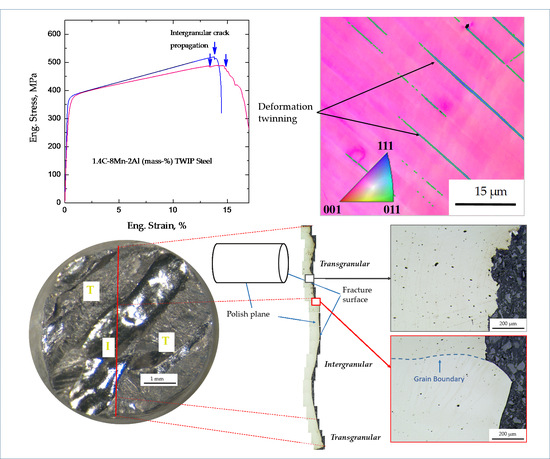
3.2. Tensile Properties and Work-Hardening Behavior

Tensile stress–strain curves for one of the specimens in each route are shown in Figure 2. A characteristic feature of the stress–strain curves is the occurrence of stress drops, as marked by vertical arrows in Figure 2. These stress drops imply the formation of discontinuities in tensile specimens, leading to an abrupt decrease in their effective cross-section. Accordingly, the low total elongation of the present steel compared to conventional high-Mn steels [24] might be related to the formation of discontinuities of supercritical size during tensile tests, leading to the premature fracture of tensile specimens.
In spite of the presence of a high C concentration, the yield strength of the present steel remains below 371 MPa, which is comparable or somewhat lower than that of the conventional and Al-added high-Mn steels containing C concentrations up to only 0.7 mass % [25]. Due to the significant influence of grain size on the yield strength of austenitic steels [26], the relatively low yield strength of the present steel can be justified by its coarse grain size. Average tensile elongations until fracture in HM and MH conditions were 14.9% and 14.6%, respectively. The similarity of the total elongation for HM and MH specimens indicates that the mechanism responsible for the premature fracture of tensile specimens is operative regardless of the sequence of machining and heat treatment steps. Since the work-hardening rate is largely controlled by texture [27], the difference in the work-hardening rate of specimens might be related to the coarse grain size of specimens, and accompanied textural differences. Furthermore, reduction in the work-hardening rate of polycrystalline tensile specimens can also arise if the cross-section is compromised by the formation of discontinuities, for instance, surface cracks [28]. The likelihood of this mechanism is discussed in Section 3.3.

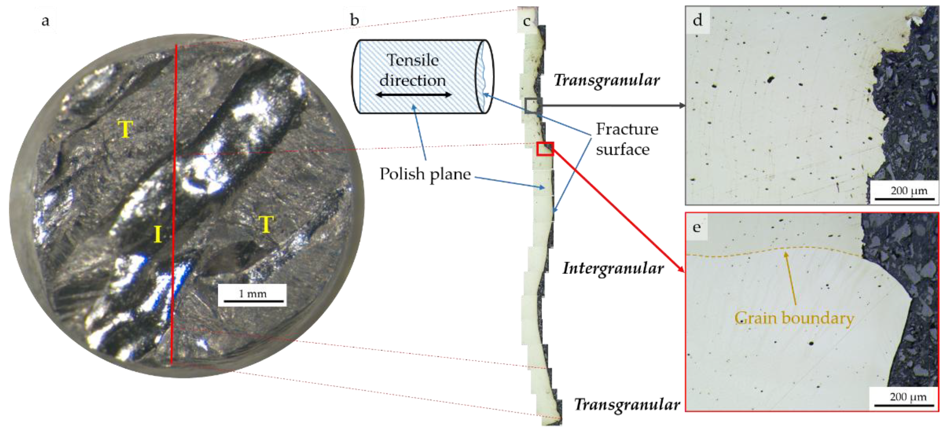
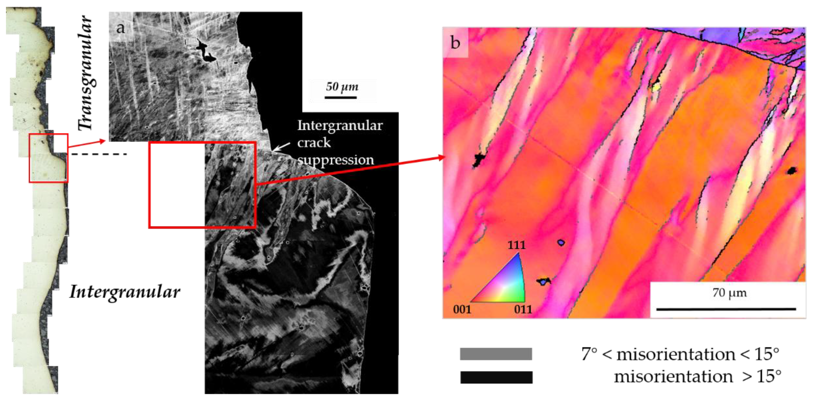
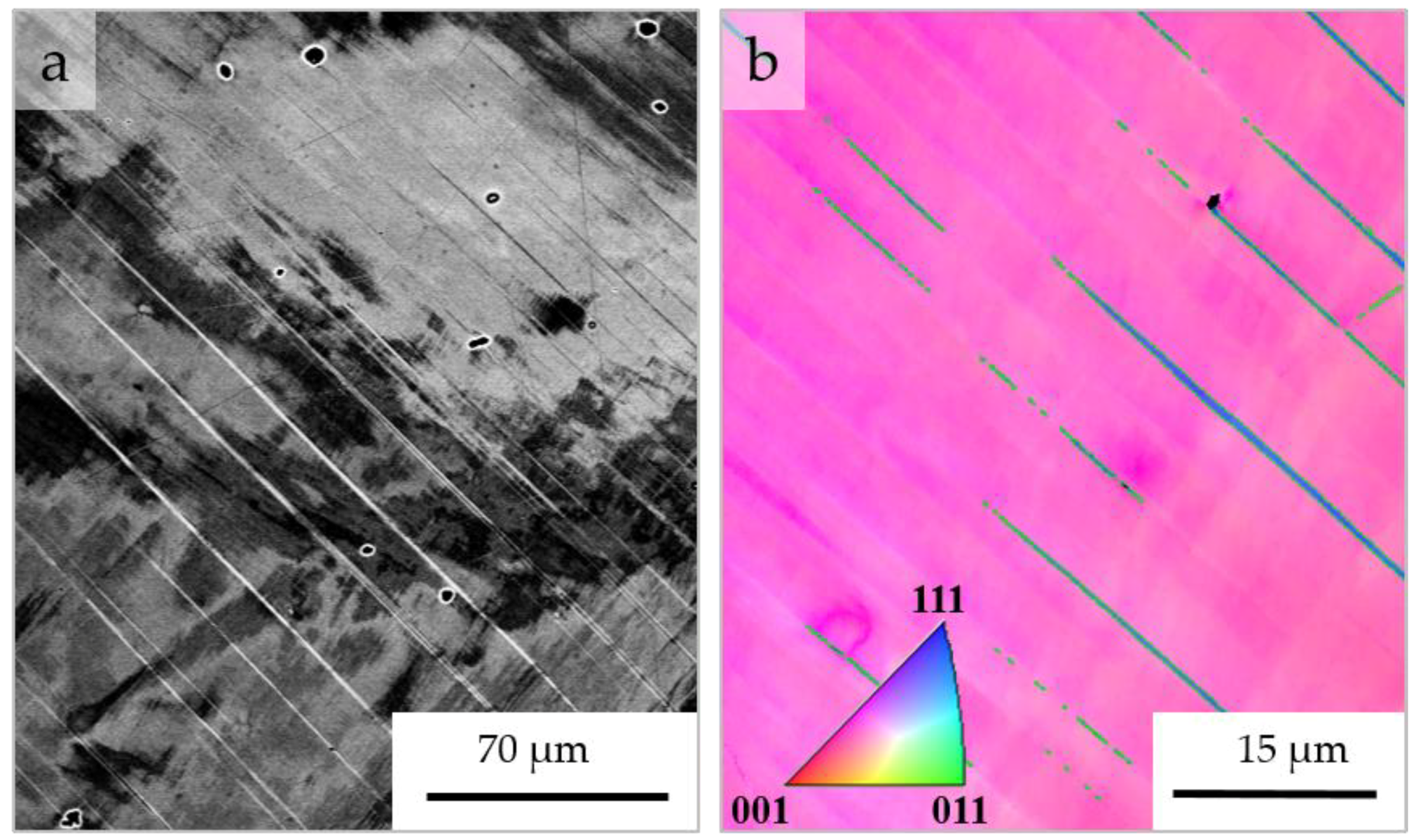
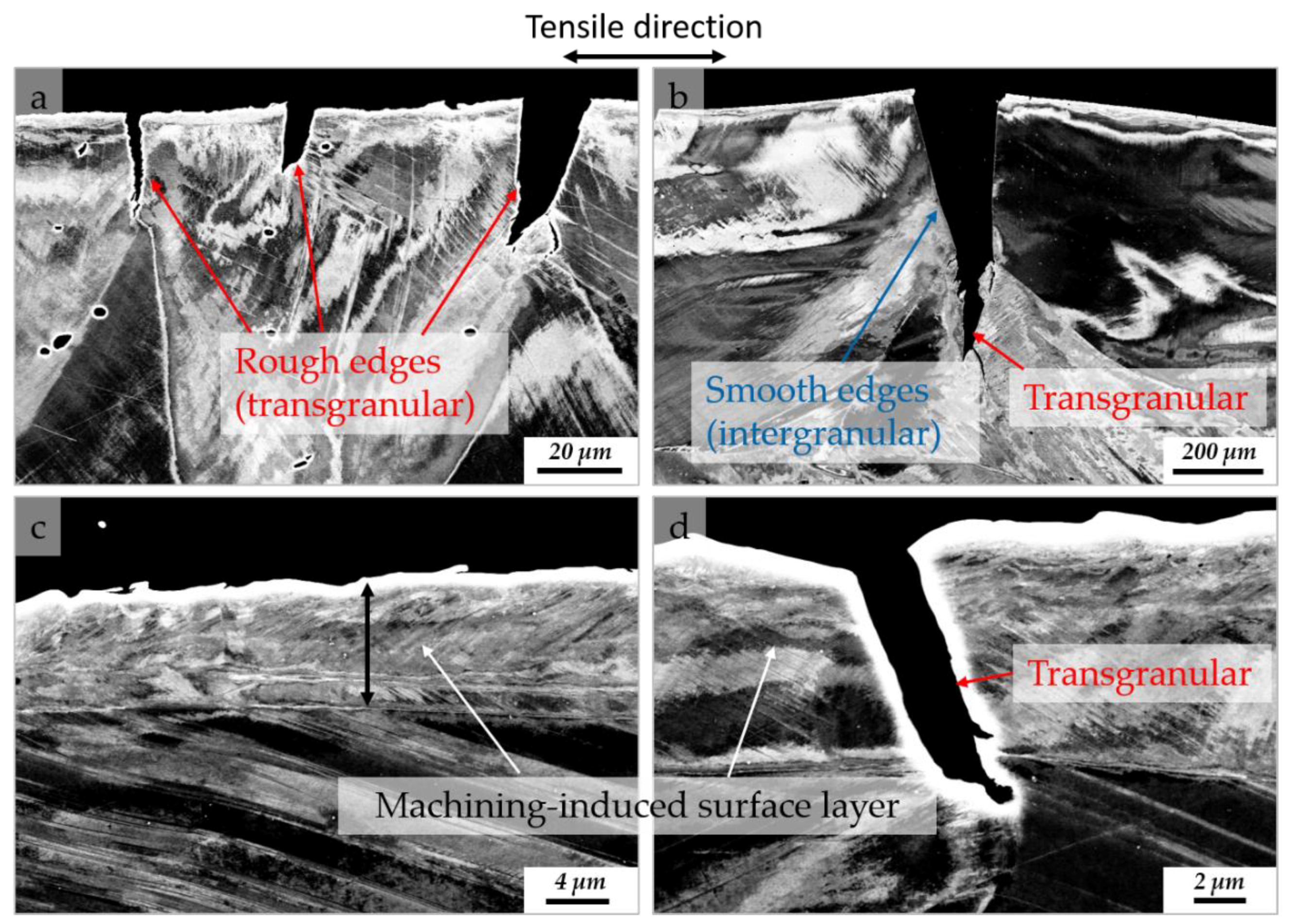
3.3. Macro- and Microstructural Examination of Fractured Tensile Specimens

Fracture surface of the tensile specimen HM is shown in Figure 3a. Two regions with distinct contrasts can be identified on the fracture surface. In the regions marked T, the fracture surface appears matt. The regions with a matt appearance are separated by a shiny region, marked I in Figure 3a. Smaller regions with a shiny contrast also exist near some of the edges of tensile specimens. The difference in the light reflection characteristics of the fracture surface can be correlated with the roughness of the fracture surface. The better-reflecting shiny regions are expected to be smoother than regions with a matt appearance. To confirm this, the opposite side of the fracture surface in Figure 3a was mounted according to the schematic in Figure 3b. The contour shown in Figure 3c corresponds approximately to the solid line superimposed on the fracture surface in Figure 3a. The dashed lines extending from Figure 3a–c mark the approximate correspondence between the fracture surface and its contour. The areas demarcated by two rectangles in Figure 3c are magnified in Figure 3d,e. According to Figure 3d, the fracture surface is rough in the regions marked T. The roughness of the fracture surface in Figure 3d indicates the occurrence of noticeable plastic deformation prior to fracture. By contrast, the fracture surface is smooth in the regions marked I (Figure 3e). The results support that the regions marked T and I represent transgranular and intergranular types of fracture, respectively.
An electron channeling contrast imaging (ECCI) micrograph pertaining to the region of fracture mode transition from intergranular to transgranular is shown in Figure 4a. In the upper region of the ECCI micrograph, where the fracture mode is transgranular, the ECCI contrast is poor, and resembles that of highly deformed austenitic steels [29,30,31]. In the lower regions with an intergranular fracture mode, the contrast resembles that of austenitic steels having undergone a smaller degree of plastic deformation [30]. This suggests that fracture has been initiated by decohesion along the grain boundaries, leading to the formation of the central region marked I in Figure 3a. The growth of the intergranular crack has been suppressed at the point marked by an arrow on the ECCI micrograph. The suppression of the intergranular fracture is likely related to the gradual change in the orientation of the grain boundary with respect to the loading axis. In other words, the gradual deviation of the normal to the grain boundary from the tensile loading axis (horizontal in the ECCI micrograph) decreases the effective stress on the grain boundary, leading to the initiation of transgranular fracture. In this case, the crack grows in such a manner that the fracture plane remains more or less perpendicular to the tensile direction. Referring to the stress–strain curve of the specimen HM (Figure 2), the abrupt stress decrease marked by a vertical arrow arises from the occurrence of intergranular decohesion and its rapid propagation. The associated decrease in the cross-sectional area in regions of intergranular decohesion, in turn, increases the stress carried by the rest of the cross-section, thereby triggering the void formation and the transgranular mode of fracture. The occurrence of localized deformation also leads to local strain rates much higher than the global strain rate. The EBSD inverse pole figure (IPF) map in Figure 4b, pertaining to the region demarcated by a rectangle in the ECCI micrograph of Figure 4a, indicates the presence of bands with large misorientations with respect to the surrounding matrix. The bands have also propagated into apparently stress-free cross-sectional regions having experienced grain boundary decohesion. They resemble the shear bands that are normally triggered at high deformation rates [32]. Since intergranular decohesion relieves the stress on the separated grain boundaries, strain compatibility with regions above the nearly horizontal segment of the grain boundary—regions that continue to deform subsequent to intergranular decohesion—must be responsible for the occurrence of bands with large misorientations.
Further ECCI and EBSD examinations of the fractured HM specimen revealed the occurrence of deformation twins during tensile deformation (Figure 5). This indicates the ability of the present alloy system to exhibit the TWIP effect. Nevertheless, tensile elongations until fracture for the present medium-Mn high-C steel remain below 18%, significantly smaller than those for conventional high-Mn TWIP steels [24]. To identify the origin of poor tensile ductility in the present TWIP steel, the outer surface in the gauge section of the fractured tensile specimen HM was examined. As exemplified in Figure 6, a high density of surface cracks was detected on the surface of tensile specimen. All of the surface cracks in the polished section, shown in Figure 6a, are transgranular. This interpretation is also compatible with the small spacing of the surface cracks in Figure 6b compared to the grain size of the present steel. In other words, surface cracks do not necessarily form at grain boundaries. The formation of surface cracks in the case of both HM and MH specimens suggests that the observed difference in their work-hardening rate might be partly due to the difference in the occurrence frequency and depth of cracks on their outer surface.
The ECCI micrographs in Figure 7 provide a magnified view of the surface cracks in the tensile-tested specimen HM. The cracks with rough edges in Figure 7a are not associated with grain boundaries. Figure 7b, on the other hand, is an example of an intergranular surface crack with smooth edges that has evolved into a transgranular crack with rough edges during its growth into the inner sections of the tensile specimen. The preceding transition can be justified by the deviation of the grain boundary plane normal from the tensile direction, and an associated decrease in the stress applied to the deflected grain boundary. This scenario is very similar to the transition from intergranular to transgranular fracture on the fracture surface (Figure 4a). A possible reason for the occurrence of surface cracks is the existence of pre-existing defects at the surface of tensile specimens. The uniform surface layer with an average thickness of 8 μm in Figure 7c,d is expected to have been induced during the machining of tensile specimens. Nevertheless, machining effects also exist at the surface of austenitic steels exhibiting significantly higher tensile elongations compared to the present steel [33]. Furthermore, cracks were also observed on the outer surface of the tensile-tested MH specimen (not shown), where the damage due to machining had been eliminated by the subsequent heat treatment.
Based on the previous discussions, the occurrence of a high frequency of surface cracks might be due to the activation of an embrittlement mechanism, particular to high-C austenitic steels. Due to the high proportion in the fracture surface of regions exhibiting intergranular fracture mode, surface cracks are particularly detrimental when they coincide with grain boundaries perpendicular to the tensile direction. In such cases, rapid crack growth along the grain boundaries leads to a significant decrease in the cross-section of tensile specimens, and localized deformation of regions with a compromised cross-sectional area. In the absence of grain boundaries with a proper orientation for crack propagation, the fracture mode would be transgranular.

4. Conclusions

Tensile properties of the Fe–1.44C–8Mn–1.9Al (mass %) steel with a fully austenitic microstructure, obtained by rapid quenching from the austenite range to suppress the precipitation of cementite, was determined at room temperature. Tensile tests were performed using specimens prepared in two different routes involving an exchanged sequence of machining and heat treatment as the last processing steps prior to tensile tests. In spite of the occurrence of deformation twinning, total tensile elongations in both processing routes remained below 18%, much smaller than those for conventional high-Mn TWIP steels. Abrupt stress drops during tensile tests suggested the occurrence of discontinuities in tensile specimens. Detailed examination of the fracture surface indicated a mixed intergranular–transgranular fracture mode. Furthermore, a high density of surface cracks was observed near the outer surface in the gauge section of fractured tensile specimens. The origin of surface cracks could not be identified. The coincidence of surface cracks with the grain boundaries, especially those nearly perpendicular to the tensile direction, is thought to be responsible for the accelerated grain boundary decohesion and the premature fracture of tensile specimens.

Author Contributions

J.M. and G.L. conceived and designed the experiments; G.L. performed the experiments; G.L., J.M., and O.V. analyzed the data; O.V. provided materials and analysis tools; G.L. and J.M. wrote the paper.

Acknowledgments

G.L. would like to thank the China Scholarship Council (CSC) for providing scholarship. Thanks are also due to the technical staff at the Institute of Iron and Steel Technology of TU Bergakademie Freiberg.

Conflicts of Interest

The authors declare no conflict of interest.

References

  1. Hwang, S.W.; Ji, J.H.; Park, K.-T. Effects of Al addition on high strain rate deformation of fully austenitic high Mn steels. Mater. Sci. Eng. A 2011, 528, 7267–7275. [Google Scholar] [CrossRef]
  2. Chen, M.-S.; Cheng, H.-C.; Huang, C.-F.; Chao, C.-Y.; Ou, K.-L.; Yu, C.-H. Effects of C and Cr content on high-temperature microstructures of Fe–9Al–30Mn–xC–yCr alloys. Mater. Charact. 2010, 61, 206–211. [Google Scholar] [CrossRef]
  3. Yoo, J.D.; Park, K.-T. Microband-induced plasticity in a high Mn–Al–C light steel. Mater. Sci. Eng. A 2008, 496, 417–424. [Google Scholar] [CrossRef]
  4. Cooman, B.C.D.; Chen, L.; Kim, H.S.; Estrin, Y.; Kim, S.K.; Voswinckel, H. State-of-the-Science of High Manganese TWIP Steels for Automotive Applications. In Microstructure and Texture in Steels; Springer: London, UK, 2009; pp. 165–183. ISBN 978-1-84882-453-9. [Google Scholar]
  5. Sohn, S.S.; Hong, S.; Lee, J.; Suh, B.-C.; Kim, S.-K.; Lee, B.-J.; Kim, N.J.; Lee, S. Effects of Mn and Al contents on cryogenic-temperature tensile and Charpy impact properties in four austenitic high-Mn steels. Acta Mater. 2015, 100, 39–52. [Google Scholar] [CrossRef]
  6. Choi, J.K.; Lee, S.-G.; Park, Y.-H.; Han, I.-W.; Morris, J.W.J. High Manganese Austenitic Steel For Cryogenic Applications. In Proceedings of the Twenty-second International Offshore and Polar Engineering Conference, Rhodes, Greece, 17–22 June 2012. [Google Scholar]
  7. Lee, C.-Y.; Jeong, J.; Han, J.; Lee, S.-J.; Lee, S.; Lee, Y.-K. Coupled strengthening in a medium manganese lightweight steel with an inhomogeneously grained structure of austenite. Acta Mater. 2015, 84, 1–8. [Google Scholar] [CrossRef]
  8. Tsuchiyama, T.; Inoue, T.; Tobata, J.; Akama, D.; Takaki, S. Microstructure and mechanical properties of a medium manganese steel treated with interrupted quenching and intercritical annealing. Scr. Mater. 2016, 122, 36–39. [Google Scholar] [CrossRef]
  9. Zhang, Y.; Wang, L.; Findley, K.O.; Speer, J.G. Influence of Temperature and Grain Size on Austenite Stability in Medium Manganese Steels. Metall. Mater. Trans. A 2017, 48, 2140–2149. [Google Scholar] [CrossRef]
  10. Ghasri-Khouzani, M.; McDermid, J.R. Effect of carbon content on the mechanical properties and microstructural evolution of Fe–22Mn–C steels. Mater. Sci. Eng. A 2015, 621, 118–127. [Google Scholar] [CrossRef]
  11. Tian, Y.Z.; Bai, Y.; Chen, M.C.; Shibata, A.; Terada, D.; Tsuji, N. Enhanced Strength and Ductility in an Ultrafine-Grained Fe-22Mn-0.6C Austenitic Steel Having Fully Recrystallized Structure. Metall. Mater. Trans. A 2014, 45, 5300–5304. [Google Scholar] [CrossRef]
  12. Suh, D.-W.; Park, S.-J.; Oh, C.-S.; Kim, S.-J. Influence of partial replacement of Si by Al on the change of phase fraction during heat treatment of TRIP steels. Scr. Mater. 2007, 57, 1097–1100. [Google Scholar] [CrossRef]
  13. Lee, S.; Cooman, B.C.D. Effect of the Intercritical Annealing Temperature on the Mechanical Properties of 10 Pct Mn Multi-phase Steel. Metall. Mater. Trans. A 2014, 45, 5009–5016. [Google Scholar] [CrossRef] [Green Version]
  14. Seo, C.-H.; Kwon, K.H.; Choi, K.; Kim, K.-H.; Kwak, J.H.; Lee, S.; Kim, N.J. Deformation behavior of ferrite–austenite duplex lightweight Fe–Mn–Al–C steel. Scr. Mater. 2012, 66, 519–522. [Google Scholar] [CrossRef]
  15. Heo, Y.-U.; Suh, D.-W.; Lee, H.-C. Fabrication of an ultrafine-grained structure by a compositional pinning technique. Acta Mater. 2014, 77, 236–247. [Google Scholar] [CrossRef]
  16. Lee, S.; Lee, K.; De Cooman, B.C. Observation of the TWIP+TRIP Plasticity-Enhancement Mechanism in Al-Added 6 Wt Pct Medium Mn Steel. Metall. Mater. Trans. A 2015, 46, 2356–2363. [Google Scholar] [CrossRef]
  17. Cai, Z.H.; Ding, H.; Misra, R.D.K.; Ying, Z.Y. Austenite stability and deformation behavior in a cold-rolled transformation-induced plasticity steel with medium manganese content. Acta Mater. 2015, 84, 229–236. [Google Scholar] [CrossRef]
  18. Allain, S.; Chateau, J.-P.; Bouaziz, O.; Migot, S.; Guelton, N. Correlations between the calculated stacking fault energy and the plasticity mechanisms in Fe–Mn–C alloys. Mater. Sci. Eng. A 2004, 387–389, 158–162. [Google Scholar] [CrossRef]
  19. Saeed-Akbari, A.; Imlau, J.; Prahl, U.; Bleck, W. Derivation and Variation in Composition-Dependent Stacking Fault Energy Maps Based on Subregular Solution Model in High-Manganese Steels. Metall. Mater. Trans. A 2009, 40, 3076–3090. [Google Scholar] [CrossRef]
  20. Seo, E.J.; Kim, J.K.; Cho, L.; Mola, J.; Oh, C.Y.; De Cooman, B.C. Micro-plasticity of medium Mn austenitic steel: Perfect dislocation plasticity and deformation twinning. Acta Mater. 2017, 135, 112–123. [Google Scholar] [CrossRef]
  21. Luan, G.; Volkova, O.; Mola, J. Design of Fully Austenitic Medium Manganese Steels. IOP Conf. Ser. Mater. Sci. Eng. 2018, 373, 012002. [Google Scholar] [CrossRef]
  22. Kozeschnik, E.; Bhadeshia, H.K.D.H. Influence of silicon on cementite precipitation in steels. Mater. Sci. Technol. 2008, 24, 343–347. [Google Scholar] [CrossRef]
  23. Mola, J.; Luan, G.; Huang, Q.; Schimpf, C.; Rafaja, D. Cementite evolution in medium manganese twinning-induced plasticity steels. Materialia 2018. [Google Scholar] [CrossRef]
  24. De Cooman, B.C.; Chin, K.; Kim, J. High Mn TWIP Steels for Automotive Applications. In New Trends and Developments in Automotive System Engineering; Chiaberge, M., Ed.; InTech: London, UK, 2011; ISBN 978-953-307-517-4. [Google Scholar] [Green Version]
  25. Yang, H.K.; Zhang, Z.J.; Tian, Y.Z.; Zhang, Z.F. Negative to positive transition of strain rate sensitivity in Fe-22Mn-0.6C-x(Al) twinning-induced plasticity steels. Mater. Sci. Eng. A 2017, 690, 146–157. [Google Scholar] [CrossRef]
  26. Dini, G.; Najafizadeh, A.; Ueji, R.; Monir-Vaghefi, S.M. Tensile deformation behavior of high manganese austenitic steel: The role of grain size. Mater. Des. 2010, 31, 3395–3402. [Google Scholar] [CrossRef]
  27. Karaman, I.; Sehitoglu, H.; Gall, K.; Chumlyakov, Y.I.; Maier, H.J. Deformation of single crystal Hadfield steel by twinning and slip. Acta Mater. 2000, 48, 1345–1359. [Google Scholar] [CrossRef]
  28. Mola, J.; Ullrich, C.; Kuang, B.; Rahimi, R.; Huang, Q.; Rafaja, D.; Ritzenhoff, R. Austenitic Nickel- and Manganese-Free Fe-15Cr-1Mo-0.4N-0.3C Steel: Tensile Behavior and Deformation-Induced Processes between 298 K and 503 K (25 °C and 230 °C). Metall. Mater. Trans. A 2017, 48, 1033–1052. [Google Scholar] [CrossRef]
  29. Rahimi, R.; Ullrich, C.; Klemm, V.; Rafaja, D.; De Cooman, B.C.; Biermann, H.; Mola, J. Influence of Al on the temperature dependence of strain hardening behavior and glide planarity in Fe–Cr–Ni–Mn–C austenitic stainless steels. Mater. Sci. Eng. A 2016, 649, 301–312. [Google Scholar] [CrossRef]
  30. Rahimi, R.; Ullrich, C.; Rafaja, D.; Biermann, H.; Mola, J. Microstructural Evolution of an Al-Alloyed Duplex Stainless Steel During Tensile Deformation Between 77 K and 473 K (−196 °C and 200 °C). Metall. Mater. Trans. A 2016, 47, 2705–2716. [Google Scholar] [CrossRef]
  31. Huang, Q.; Volkova, O.; Biermann, H.; Mola, J. Tensile elongation of lean-alloy austenitic stainless steels: transformation-induced plasticity versus planar glide. Mater. Sci. Technol. 2017, 33, 1224–1230. [Google Scholar] [CrossRef]
  32. Dieter, G.E. Mechanical Metallurgy; McGraw-Hill: New York, NY, USA, 1976; ISBN 978-0-07-016891-6. [Google Scholar]
  33. Berns, H.; Nabiran, N.; Mujica, L. High-Interstitial Stainless Austenitic Steel Castings. Steel Res. Int. 2013, 84, 119–128. [Google Scholar] [CrossRef]
Figure 1. Microstructure after brine quenching from 1150 °C; (a,b) optical micrographs; (c) SEM micrograph of an inclusion and its SEM-EDS analysis result.
Metals 08 00902 g001
Figure 2. Engineering tensile stress–strain curves for the HM and MH specimens.
Metals 08 00902 g002
Figure 3. (a) Entire fracture surface (front view) of the tensile specimen HM from stereomicroscope; (b) schematic showing how the polish plane in (c) was obtained; (c) light optical micrograph (lateral view) showing the fracture surface contour; (d,e) magnified view (lateral view) of the regions marked by rectangles in (c).
Metals 08 00902 g003
Figure 4. (a) ECCI micrograph of the region of fracture mode transition from intergranular to transgranular; (b) EBSD inverse pole figure (IPF) map of the region marked by a rectangle in the ECCI micrograph of (a). In (b), colors denote crystal directions normal to the polish plane. Misorientations in the range 7–15° and above 15°, are highlighted using gray and black lines, respectively.
Metals 08 00902 g004
Figure 5. (a) ECCI and (b) EBSD examination of the deformation twins after tensile testing. In (b), ∑3 twin boundaries are highlighted in green. In the EBSD IPF map of (b), colors denote crystal directions normal to the polish plane.
Metals 08 00902 g005
Figure 6. Surface cracks in the gauge section of the tensile-tested HM specimen: (a) cracks as seen on the polish plane; (b) cracks as seen on the outer surface.
Metals 08 00902 g006
Figure 7. ECCI micrographs taken from regions near the surface of the tensile-tested HM specimen; (a) transgranular cracks; (b) crack mode transition from intergranular to transgranular; (c) magnified view of the machining-induced surface layer; (d) magnified view of a transgranular crack in the machining-induced surface layer.
Metals 08 00902 g007
Table 1. Chemical composition of the steel used in the present study (mass %).
Steel IDCMnAlSiFe + Impurities
2Al (HM, MH)1.448.01.90.005Balance

