Article

Inhibition Effect of Ti on the Formation of Martensite Lath in 14Cr Oxide Dispersion Strengthened Steel

State Key Lab of Hydraulic Engineering Simulation and Safety, School of Materials Science & Engineering, Tianjin University, Tianjin 300354, China
*
Authors to whom correspondence should be addressed.
Metals 2018, 8(10), 802; https://doi.org/10.3390/met8100802
Submission received: 10 September 2018 / Revised: 23 September 2018 / Accepted: 24 September 2018 / Published: 8 October 2018

Abstract

:
Three model powders defined as MP powders (milled pre-alloyed powders), mixed powders (MX, 50 wt.% MP powders + 50 wt.% Oxide-Dispersion Strengthened powders) and Oxide Dispersion Strengthened (ODS) powders (alloyed pre-alloyed powders with the addition of Ti and Y2O3) are obtained under identical ball milling parameters. These powders are then consolidated under same sintering condition by spark plasma sintering (SPS) in order to investigate the formation mechanism of martensite lath in the MP steel and the effect of Ti on the stability of ferrite. The results indicate that the addition of Y2O3 and Ti powders can act as friction material during the mechanical alloying process, thus promoting the refinement effect. The formation of martensite lath in the MP steel is attributed to the local Cr depletion resulted from the large amounts of M23C6 precipitation. Ti possesses a strong affinity to C and long range diffusion ability, which efficiently prevents the martensite lath formation and local Cr depletion. Present study supports the conclusion that the lack of martensite in the MX and ODS steel is due to the addition of Ti. Secondary phases in these steels are identified and analyzed as well.

Graphical Abstract

1. Introduction

The oxide dispersion strengthened (ODS) steel possesses superior high temperature properties [1,2,3] and excellent irradiation resistance [4,5,6,7], and is a promising structural material in future nuclear reactors that are designed to operate at severe service circumstances. The uniformly distributed nanoparticles in the matrix play a key role in the outstanding performance of ODS steel. The nanoparticles can not only prevent dislocation migration and grain boundary motion but also act as the sinking points for irradiation induced defects, such as transmutation product helium, excess vacancies and self-interstitial atom defects [8,9,10].
The balance between strength and ductility is always the key issue for the materials especially for using in critical applications. In order to effectively improve the ductility without the reduction of strength, lots of researchers have obtained a bimodal structure by controlling the powder metallurgy process [11,12]. Powder metallurgy consists of ball milling process and subsequent consolidation of milled powders. The perfect combination of superior strength and ductility has been improved by experiments and model calculations in an ultrafine Ti-Fe-Nb alloy, carbon steel, polycrystalline copper, stainless steel, and ferritic steel [13,14,15,16,17,18,19]. Since the powder metallurgy method is generally used in the fabrication process of ODS steel, the bimodal structure also attracts the interests of some researchers [18,20,21,22]. Auger et al. [20] have compared the differences between ODS and non-ODS steel fabricated by spark plasma sintering (SPS) and found that both the ODS and non-ODS steel possess martensite lath. According to the research by Auger et al., the formation of martensite lath is probably attributed to C contamination, Cr depletion and the fast cooling rate [20]. However, Boulnat et al. [21] have fabricated the ODS steel with similar composition by SPS, and no martensite lath has been identified. In addition, Dadé et al. [22] have investigated the non-ODS steel produced by mechanical alloying and subsequent hot isostatic pressing (HIP). The researchers have found the martensite blocks in such an un-strengthened steel and tended to ascribe the phenomenon to the C and N dissolved in the matrix. Mouawad et al. [23] have identified the martensite in the atomized and milled powders and put forward the possible reasons: local carbon segregation and scarcely dispersed inclusion. According to the previous research, martensite tends to form in the un-strengthened steel produced by sintering the atomized and milled powders. Whereas the ODS steel fabricated using the same atomized powders scarcely possesses martensite, which can be attributed to the addition of Ti and Y2O3 during the mechanical alloying process [23,24,25,26,27]. However, no detailed and systematic studies on the formation of martensite are performed currently.
In this paper, comparison experiments were carried out to figure out the reason for the martensite formation. Three different steels were investigated in respect of the powder morphology and the consolidated microstructure. The milled pre-alloyed powders and the mechanically alloyed powders with element addition were investigated with the aim to find out the original differences between the non-ODS steel and ODS steel. The mixed powders consisting of the milled pre-alloyed powders and the mechanically alloyed powders were also analyzed for comparison. Tested powders were sintered by SPS under the same conditions, and the consolidated steels were investigated in detail.

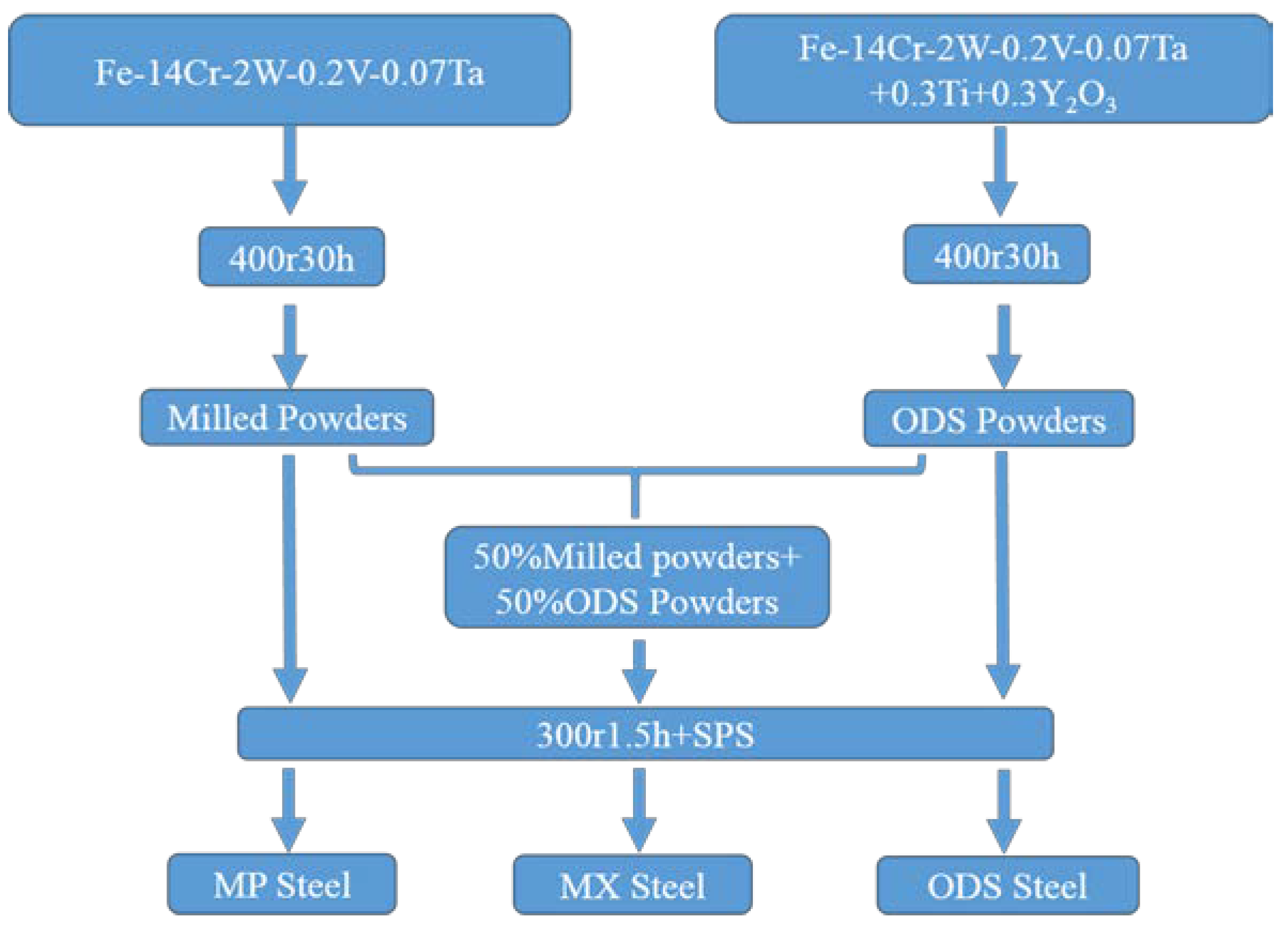
2. Experimental Procedure

Powder metallurgy is commonly used to fabricate ODS steel. The pre-alloyed powders with the nominal composition Fe–14Cr–2W–0.2V–0.07Ta (wt.%) were fabricated by the atomization method. The pre-alloyed powders were milled for 30 h at 400 rpm in stainless steel jars with a ball to powder ratio of 15:1 under high purity argon atmosphere. The obtained powders were defined as milled powders. Meanwhile, 0.3 wt.% Ti and 0.3 wt.% Y2O3 powders were added to the pre-alloyed powders and mechanically alloyed with the same milling parameters to obtain the ODS powders. The milled powders and the ODS powders were then mixed with the mass ratio of 1:1 and further milled for 1.5 h at 300 rpm, thus obtaining the uniformly mixed powders. The milled powders and ODS powders were also further milled for 1.5 h at 300 rpm for comparison. Three types of powders were finally obtained and consolidated by spark plasma sintering (SPS, Dr. Sinter SPS-625). The powders were heated to 800 °C at a rate of ~100 K/min and held for 5 min, and then heated to 1100 °C (with the same heating rate) for a soaking time of 10 min. The pressure applied during the sintering process was 40 MPa. The pressure was then removed and the consolidated samples were cooled in the furnace after sintering. The cooling rate is about 100 K/min. The sintered steels were defined as MX steel, MP steel and ODS steel respectively. The powders before SPS were defined as MX powders (50 wt.% MP powders + 50 wt.% ODS powders), MP powders (milled pre-alloyed powders), and ODS powders (alloyed pre-alloyed powders with the addition of Ti and Y2O3) consistently. The schematic graph of the experimental procedure is shown in Figure 1.
Microstructure characterization of the powders and consolidated steels was carried out through optical microscope (OM, Leica DFC 450, Leica, Solms, Germany), scanning electron microscope (SEM, SU1510, Hitachi, Tokyo, Japan) and transmission electron microscope (TEM, JEM-2100F, JEOL, Tokyo, Japan). Metallographic preparation method was used for the sample preparation of OM and SEM. The samples were mechanically grinded, polished and then etched in the solution composed of 5 g copper chloride, 100 mL hydrochloric acid, and 100 mL ethyl alcohol. Both the thin foil samples and carbon replica samples were utilized for the TEM characterization. The thin foils were electropolished in a double jet electropolishing device at −20 °C. The electrolyte consists of 5% perchloric acid and 95% ethanol. For the preparation of the carbon replica samples, a C coating method was used. The thin layer of C was detached and collected on Cu grid. A differential scanning calorimeter (DSC)/thermo gravimetric analyzer (Mettler Toledo TGA/DSC1 Star System, Mettler Toledo, Zurich, Switzerland) was used to analyze the consolidated samples. The applied thermal cycle during DSC measurement was as follows: the samples were heated to 1100 °C at a rate of 30 K/min, and then directly cooled to room temperature at 40 K/min without the holding process.

3. Results and Discussion

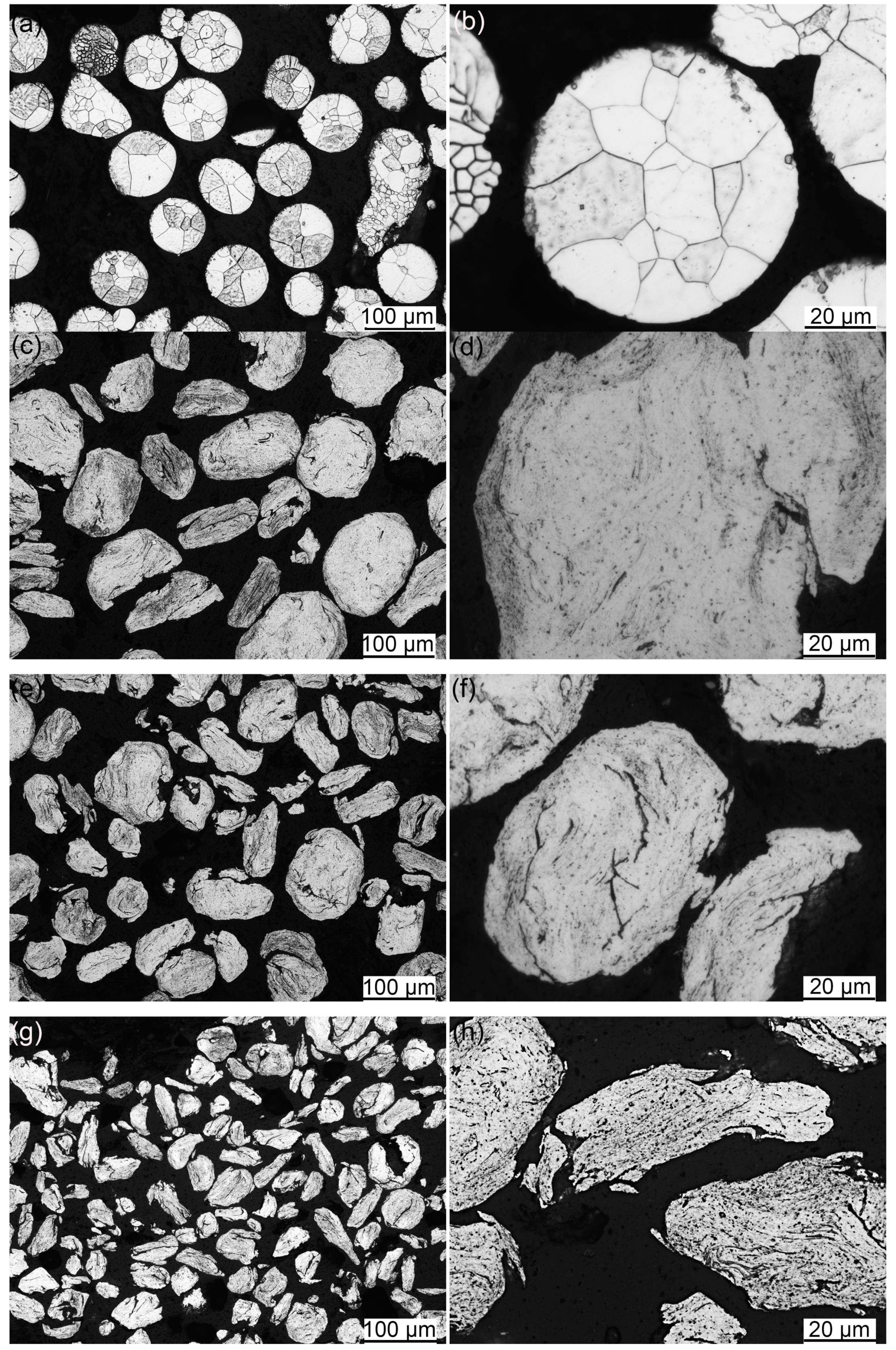
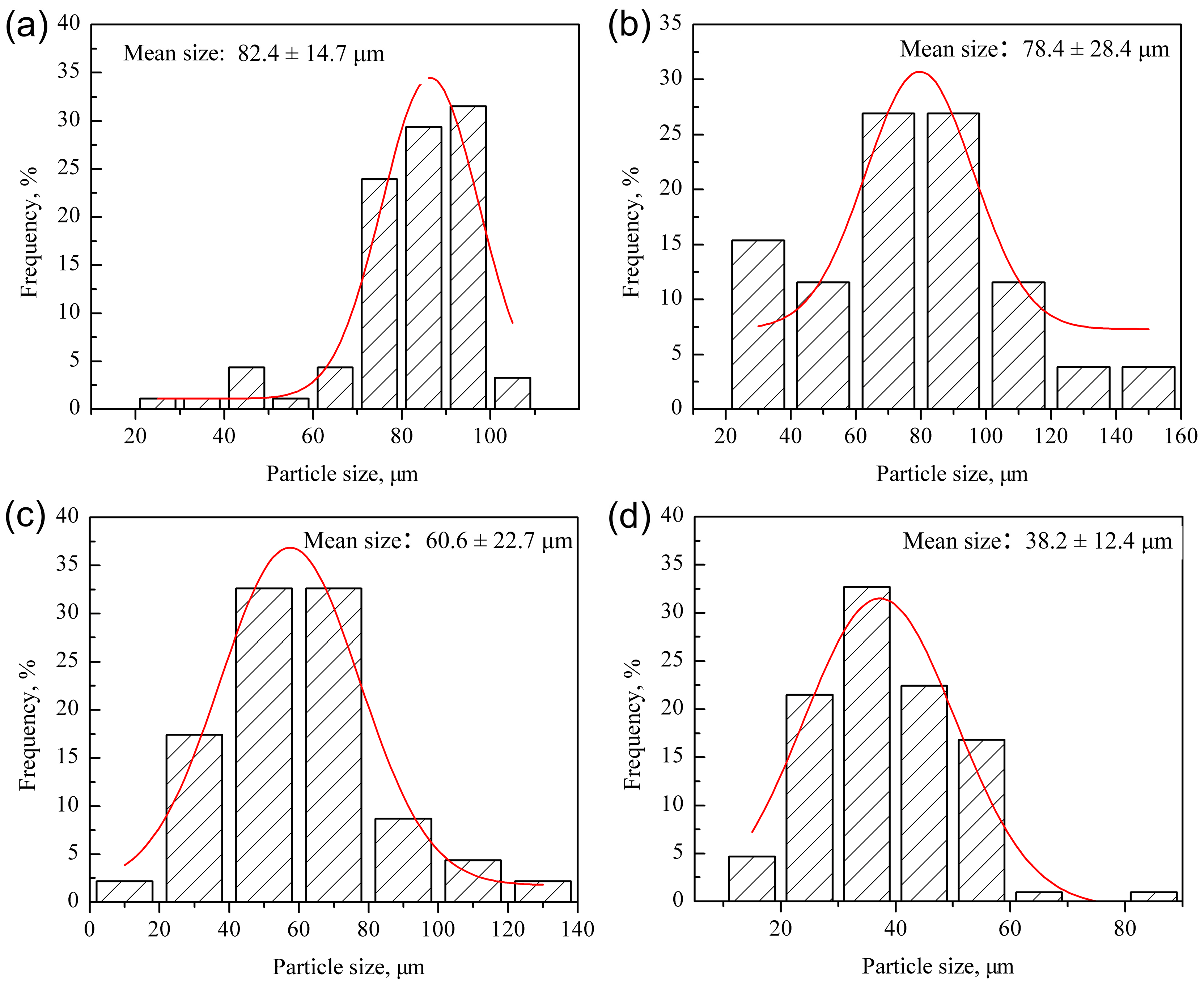
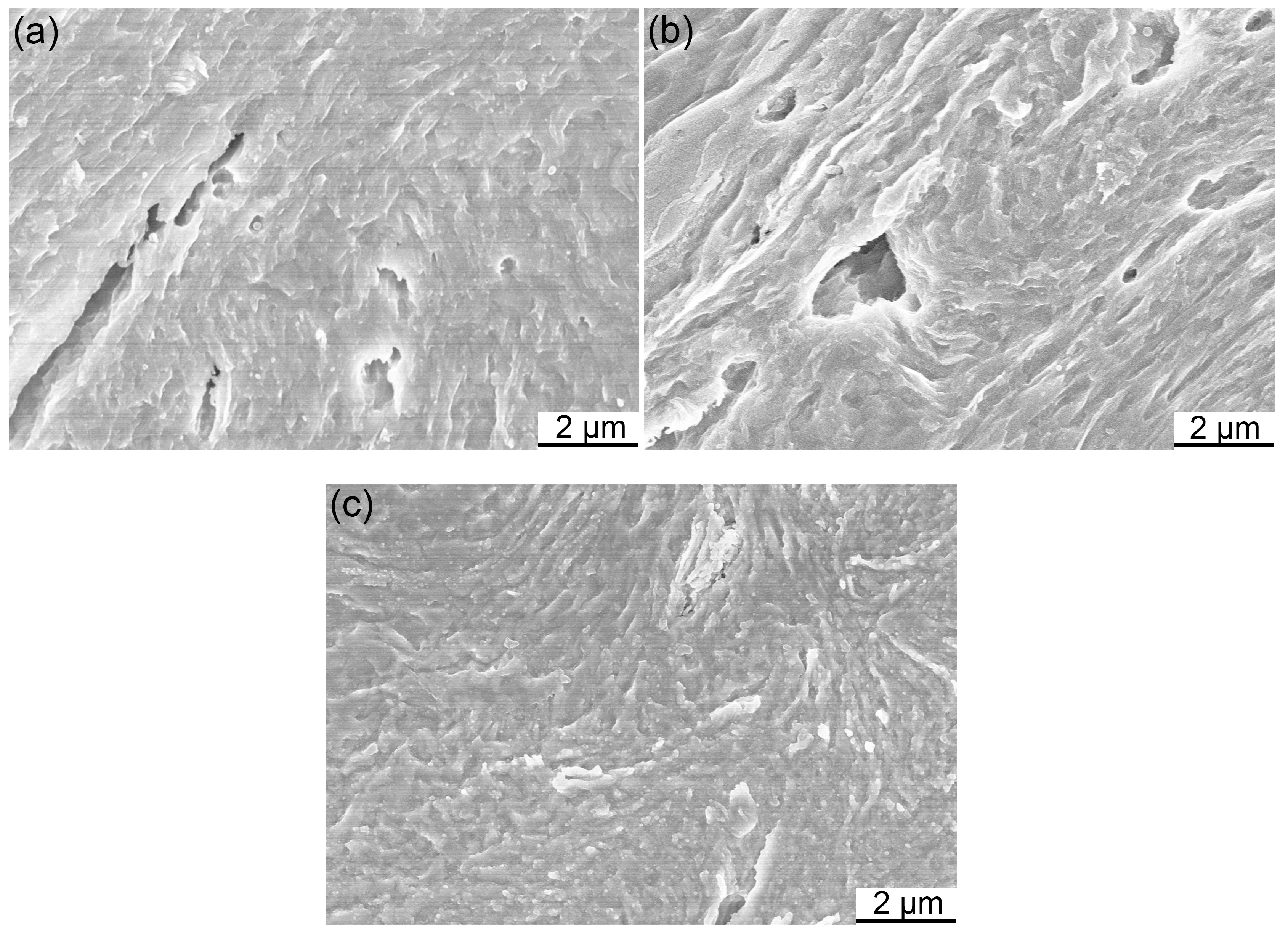
3.1. Microstructure of Powders

Figure 2 gives the OM images of used powders. Figure 2a,b presents the microstructure of the pre-alloyed powders. The pre-alloyed powders are fabricated by atomization method, which results in the generally spherical morphology of the particles. Figure 2b shows the detailed microstructure of a spherical particle. Several grains with different sizes are included in the particle, implying the inhomogeneous distribution of grain size in the pre-alloyed powders. Figure 2c depicts the morphologies of the MP powders. After twice milling with the parameters of 400 rpm 30 h and 300 rpm 1.5 h, the MP powders present the oval morphology. The detailed structure and some short cracks can be seen in Figure 2d which displays the magnified image of a particle in the MP powders. The milling process has little influence on the reduction of particle size in the pre-alloyed powders. The collision between particles and the impact between milling balls and particles fail to introduce severe plastic deformation into the pre-alloyed powders [24,28]. OM image of the MX powders is shown in Figure 2e. Part of the particles possesses the oval morphology, and the other part of the particles possesses the lamellar morphology. Particles with different morphologies are uniformly distributed in the MX powders. Figure 2f depicts the detailed microstructure of particles. As can be seen in Figure 2f, cracks exist in the middle of the oval particle, while cracks found in the lamellar particle distribute along the edge. This phenomenon means that the oval particle breaks up during milling and turns into the lamellar particle [24,25,29]. Particles in the ODS powders are presented in Figure 2g. Most of the particles possess the lamellar morphology, and the detailed microstructure in Figure 2h presents cracks distributed both in the middle and along the edge of the particles.
Particle size distribution of different powders is shown in Figure 3. The average particle sizes of the pre-alloyed, MP, MX and ODS powders are approximately 82.4 μm, 78.4 μm, 60.6 μm and 38.2 μm, respectively. According to the results shown in Figure 3a,b, it is confirmed that the milling process possesses little influence on the size reduction of the pre-alloyed powders. But the size reduction of the ODS powders is obvious, as can be seen in Figure 3c,d. The average size of the MX powders is exactly the mean value of that of the MP and ODS powders, based on the results depicted in Figure 3b–d. This phenomenon indirectly proves the uniform distribution of different particles in the MX powders. In general, particles in the ODS powders possess the smallest size when compared with the MP powders and MX powders. The results support the suggestion that addition of Ti and Y2O3 promotes the refining effect during the mechanical alloying process. The hardness of Ti and Y2O3 is higher than most of the elements in the pre-alloyed powders [24,25]. The brittle Y2O3 effectively boosts the impact effect between the powders, which promotes the crush of powders [24]. The MX powders are obtained by mixing the milled pre-alloyed powders and the mechanically alloyed ODS powders with the mass ratio of 1:1. That is the reason why the MX powders possess two kinds of particles with different morphologies. The large oval particles are originally from the milled pre-alloyed powders, and the small lamellar particles are originally from the mechanically alloyed ODS powders. The particles with different sizes and morphologies are uniformly distributed in the MX powders, meaning the excellent mixing effect at 300 rpm for 1.5 h.
SEM was utilized to characterize the microstructures of the powders at higher magnification, and the results are shown in Figure 4. Figure 4a–c presents the particle microstructures in the MP powders, MX powders, and ODS powders, respectively. Microstructures of these powders possess pores, cracks, and layer structures, which are related to the impact and extrusion effect during mechanical milling and alloying. During the mechanical milling or alloying process, the introduced Y2O3 can act as the friction material [24]. When the pores and cracks are generated inside the powder grains, the Y2O3 particles are easily trapped in such defects because of the small size. The concentration of stress would then occur along the interfaces between Y2O3 and the defects, resulting in the brittle cracking and refinement of the particles. The refinement effect is not detected in the MP powders, supporting the suggestion that the addition of Ti and Y2O3 promotes the refinement of particles.

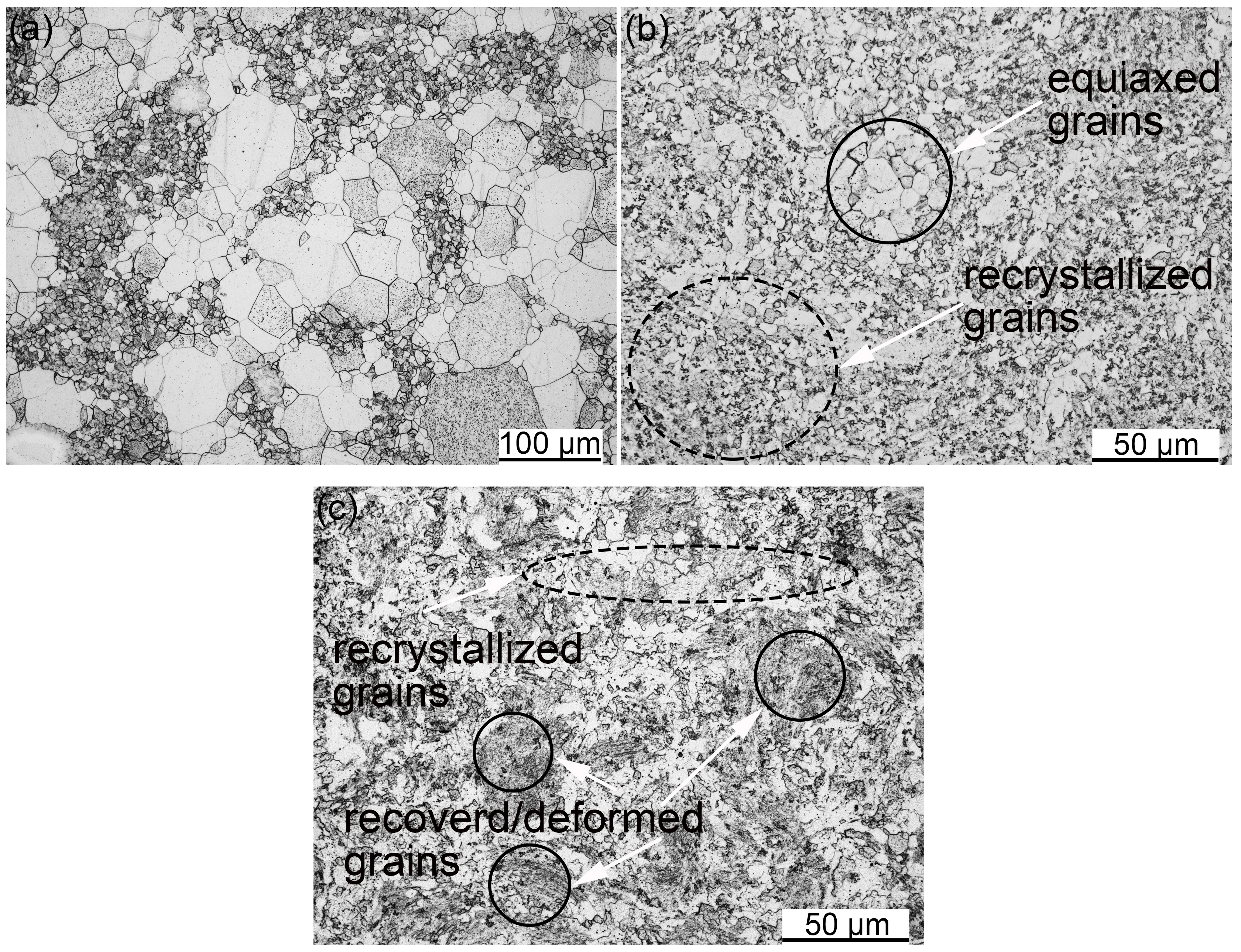
3.2. SPSed Microstructure

Figure 5a–c shows the OM images of the MP steel, MX steel and ODS steel, respectively. Microstructure of the MP steel depicted in Figure 5a possesses a bimodal character. Both large and small grains exist in the microstructure. The formation of bimodal structures is mainly ascribed to the inhomogeneous grain size of the pre-alloyed powders. All the grains present the equiaxed morphology, and the small equiaxed grains tend to distribute along the boundaries of large equiaxed grains. Figure 5b depicts the equiaxed and recrystallized grains in the MX steel. The area marked by a solid circle is full of equiaxed grains, and the area marked by the dashed ellipse is composed of recrystallized grains. Most of the grains in the MX steel are small recrystallized grains. Only a tiny fraction of the equiaxed grains exist in the microstructure. No equiaxed grains can be found in the ODS steel shown in Figure 5c. The bright area marked by the dashed ellipse in Figure 5c presents the recrystallized grains, and the dark areas marked by solid circles show the recovered/deformed grains [21].
It is difficult to clearly figure out the martensite, the recrystallized grains and the recovered/deformed grains through OM because of the limited resolution. SEM was then utilized, and the results are shown in Figure 6. The dark area in Figure 5a is magnified through SEM and shown in Figure 6a. Both ferrite and martensite can be clearly seen in the microstructure. The secondary phases distributed along the ferrite grain boundaries are carbides. Figure 6b depicts the microstructure inside the martensite blocks. Carbides distribute along the block boundaries and inside the blocks. Figure 6c gives the SEM image of the MX steel, and the area marked by a solid rectangle is magnified and displayed in Figure 6d. The microstructure shown in Figure 6c consists of large recrystallized grains and the areas without obvious grain boundaries. Such areas are composed of small recrystallized grains as can be seen in Figure 6d. Microstructure of ODS steel also consists of the recrystallized grains, seen in Figure 6e, and the areas without obvious grain boundaries in Figure 6f. However, the area without obvious grain boundaries in ODS steel is proven to be the recovered/deformed grains [21,25], which is different with the MX steel.
Powder differences before consolidation play a decisive role in the microstructure differences among these SPSed steels. The inhomogeneous grain size of the pre-alloyed powders results in the bimodal equiaxed grains in the MP steel. The ODS steel microstructure should be ascribed to the grain size disparity of the pre-alloyed powders and the severe plastic deformation during the mechanical alloying process [26,27], as well as the pinning effect of the nanoparticles precipitated during the consolidation process [8,10]. Both the MP powders and ODS powders are included in the MX powders, but microstructure of the MX steel is more similar to the ODS steel. According to the microstructure analysis, we assume that Ti in the MX powders can effectively diffuse and form an approximately uniform distribution in the overall matrix. Y2O3 can only form a uniform distribution in the area originally from the ODS powders because of the low diffusion rate. The recovery and recrystallization of the grains may be hindered by the precipitated Y-Ti-O nanoparticles, which promotes the formation of microstructure similar to the ODS steel [25].
In order to further investigate the phase transformation behavior of these samples, the DSC curves of the MP, MX and ODS steels are tested and shown in Figure 7. The peak in the curve for MP steel is due to the martensite, and no transformation peaks can be found in the DSC curve of the MX and ODS steel. The existence of martensite in the MP steel is further identified.
Whether the martensite is generated in the SPSed steel is related to the addition of Ti. Large amounts of precipitated M23C6 particles in the MP steel leads to the depletion of Cr in local areas. Martensite transformation would occur with a lower content of Cr, according to the Fe-Cr phase diagram [30]. Therefore, local depletion of Cr promotes the martensite transformation. Some researchers suggest that segregation of C can also promote the generation of martensite [18]. The contamination of C is inevitable both in the pre-alloyed powders and during the mechanical milling or alloying process [31,32,33]. All the SPSed steels undergo the same powder metallurgy process, so the amount of C contamination should be same in all cases. However, no martensite can be found in the MX and ODS steel, which means that the formation of martensite in the MP steel cannot be simply attributed to the segregation of C. The major difference between the MX steel and the ODS steel is the addition of Ti and Y2O3. Y2O3 particles act as the pinning points for dislocation motion and grain boundaries migration, which plays a key role in ODS steel. Moreover, Y2O3 is able to combine with Ti, forming the Y-Ti-O nanoparticles [34,35,36,37,38,39]. The main aim of Y2O3 addition is to improve the dispersion strengthening effect and irradiation resistance of the ODS steel. Besides the formation of Y-Ti-O nanoparticles, Ti can also act as a stabilizer that prevents the formation of Cr carbides via the generation of TiC [40,41]. Since Ti atoms have higher affinity with C than Cr, TiC precipitates are preferentially formed, which effectively prevents the Cr depletion. That is the reason why no martensite transformation occurs in the ODS steel. Martensite cannot be found in the MX steel either. Based on the analysis about the powders for consolidation, the mechanically milled pre-alloyed powders and the mechanically alloyed ODS powders are uniformly mixed in the MX powders. The regions containing Ti and the regions without Ti are uniformly distributed in the MX powders. Same as the ODS steel, martensite did not generate during the consolidation process of the MX steel, which proves the effective diffusion of Ti in the microstructure of MX powders during SPS process. This phenomenon is consistent with the long-range distribution ability of Ti in the ferritic ODS steel, which is mentioned by West [25]. According to the performed analysis, it can be concluded that the prevention of martensite formation in the MX steel and ODS steel is mainly attributed to the stabilizing effect and long-range distribution ability of Ti. In addition, experimental data support the assumption of the effective diffusion of Ti in the MX steel.
Figure 8 shows the microstructure of the MP steel in TEM images. The coarse martensite lath in the MP steel is depicted in Figure 8a. Large amounts of dislocations are distributed inside the martensite lath. Figure 8b displays the coarse martensite lath distributed along the grain boundary of ferrite. Figure 8c presents the fine martensite lath in the MP steel, and the corresponding selected area electron diffraction (SAED) is shown in Figure 8d. The diffraction points marked by solid circles are identified as martensite, and the points marked by solid rectangles are identified as re-diffraction spots of martensite. Both coarse and fine martensite lath exist in the MP steel. C contamination is finite and far less than the content with which the martensite twins would generate, resulting in the formation of martensite with single lath morphology [42,43]. Figure 8e,f gives the width distribution of coarse and fine martensite lath, respectively. The average width of coarse martensite lath is approximately 246.7 μm, and the average size of fine martensite lath is approximately 47.2 μm. Difference between the coarse martensite lath and the fine martensite lath is attributed to the grain size of austenite. The fine martensite lath originates from the ultra-fine austenite restricted by fine carbides [42,44,45].
Figure 9a shows the TEM microstructure of the MX steel. The size of grains ranges from several hundred nanometers to several micrometers. Distribution of particles in the micro-sized grain is shown in Figure 9b. The histogram inserted in Figure 9b is the size distribution of the nanoparticles precipitated in the micro-sized grains. The average size of these particles is approximately 20 nm, and the crystal structure of these particles will be discussed in next section. The MX powders before consolidation are composed of mechanically milled pre-alloyed powders and mechanically alloyed ODS powders. Therefore, the bimodal structure of the MX steel is probably due to the mixed particles with different morphology and size, as well as the inhomogeneous grain size of the initial pre-alloyed powders. As has been concluded in the previous analysis, Ti is able to effectively diffuse and form a uniform distribution in the matrix of steel. But the diffusion rate and solubility of Y in the matrix is much lower than Ti [25,46,47], resulting in the inhomogeneous distribution of Y in the MX steel. The distribution of Y-Ti-O particles is thus heterogeneous in the overall microstructure of the MX steel. The areas where the nanoparticles generated tend to possess small grains, and the areas without nanoparticles tend to present large grains. The MX powders before consolidation are gained by fully mixing two kinds of powders, so the MX steel possesses such microstructure in which the areas with Y-Ti-O nanoparticles and areas free of Y-Ti-O nanoparticles are uniformly distributed integrally.
Figure 10 depicts the TEM microstructure and the corresponding grain size distribution of the ODS steel. As can be seen in Figure 10a, both large and small grains exist in the microstructure, and the size distribution in Figure 10b also shows a bimodal character. Two peaks within micron and nanometer ranges can be seen in the histogram, respectively. Bimodal structure of the 14Cr ODS steel has been analyzed in the previous work [39].

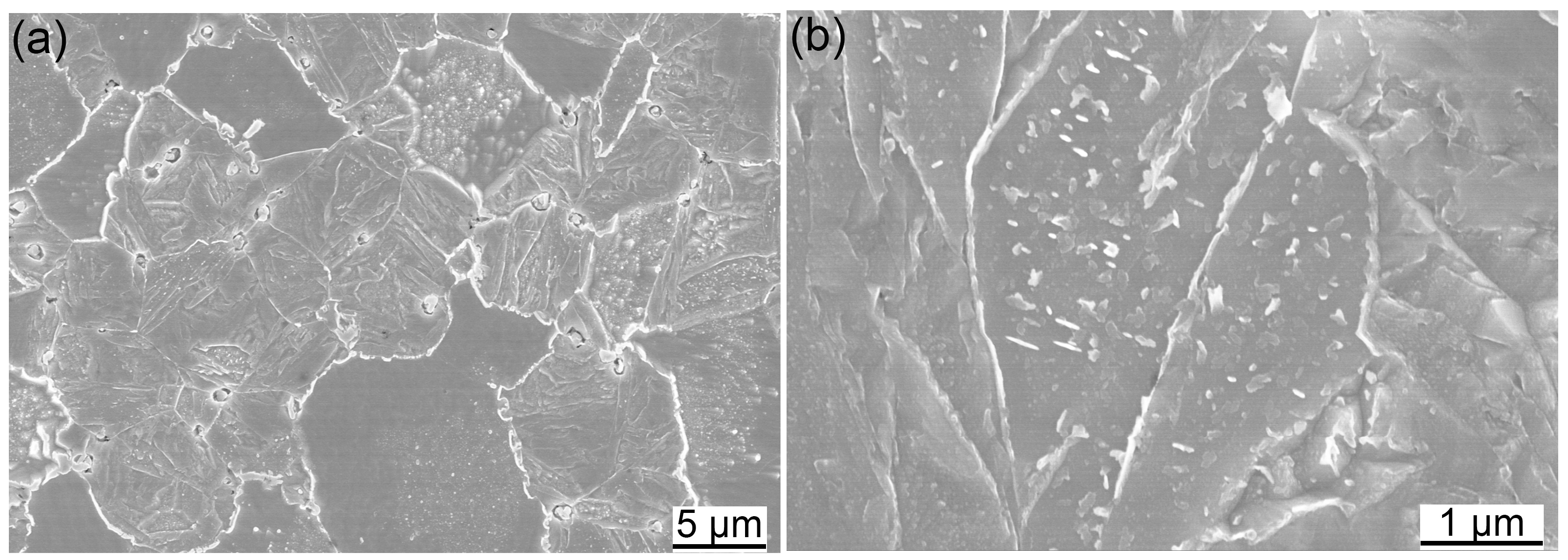
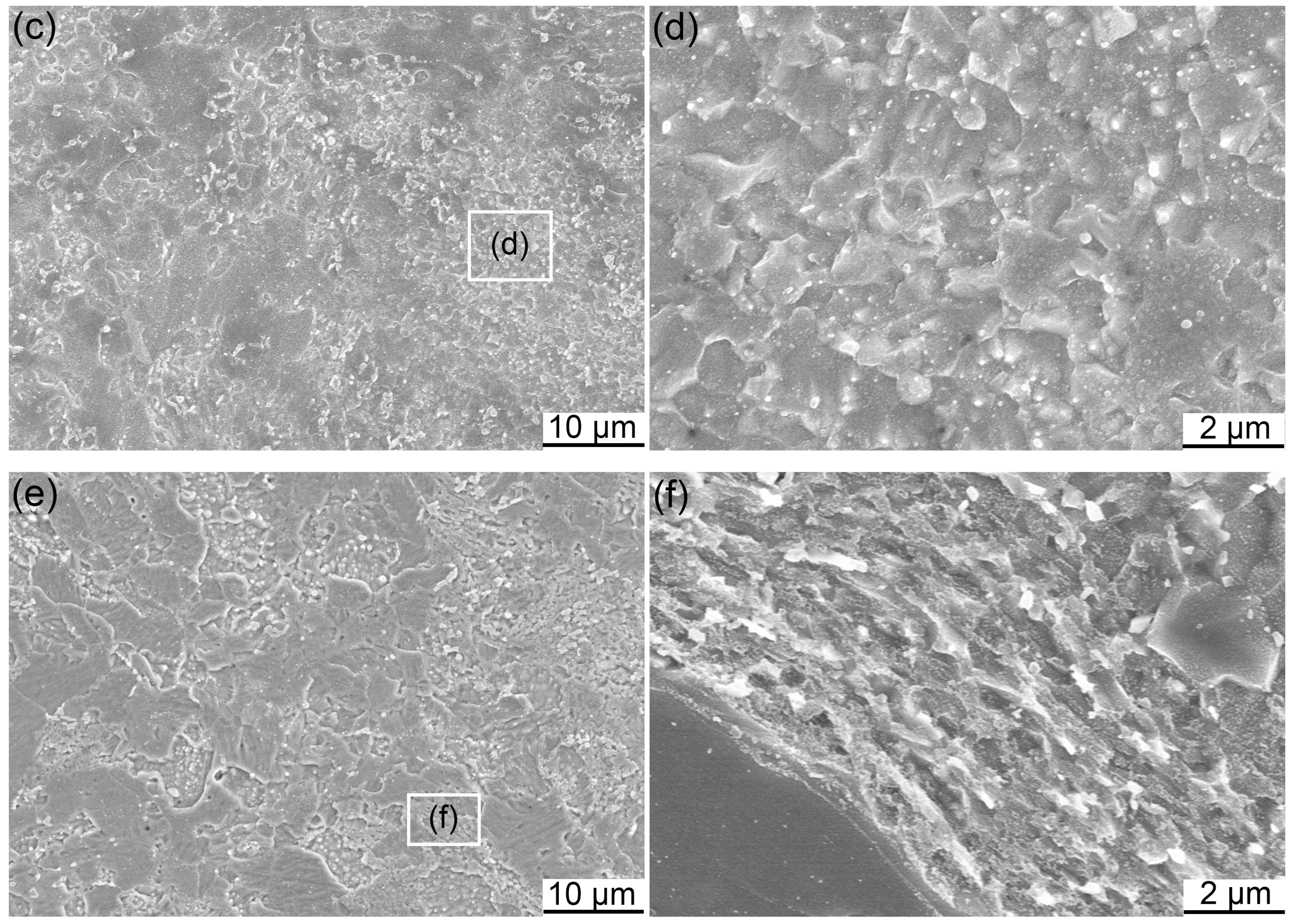
3.3. Secondary Phases

Figure 11 displays the secondary phases in the MP steel and the corresponding EDS, SAED and fast fourier transform (FFT) patterns. The secondary phases distributed along the triple junction grain boundaries are shown in Figure 11a. Figure 11b shows the large secondary phases marked in Figure 11a,c depicts the small secondary phases marked in Figure 11a. EDS analysis results of the particles marked 1 to 4 in Figure 11a are shown in Figure 11e. All of the particles are carbides on the basis of the EDS results. Particle 1 and particle 3 are rich in Fe and Cr. Particle 2 is rich in Ta. Particle 4 is rich in Cr and Ta. According to the SAED results particle 1 is identified as M23C6, where M is Fe or Cr. The Fe (Cr) rich particles with similar morphologies can be probably identified as M23C6. The size of particle 2 is smaller than the other three particles, and can be identified as TaC on the basis of EDS result. Particle 4, with its large size, is rich in Cr and Ta. It would be the segregation of TaC and M23C6. Since the TaC particle possesses a small size, it is easy to be surrounded by M23C6. The FFT patterns of the particles marked by 5 and 6 are also displayed in the figure. Particle 5 with rectangle morphology is identified as TaC, and particle 6 with spherical shape is identified as M23C6. In general, the large carbides with the average size of hundreds of nanometers in the MP steel are M23C6 particles. The small carbides with the average size of 20 nm are TaC particles. In addition, small quantities of particles with a size of 5 nm also exist in the MP steel. The content of Ta is much lower than Cr in the pre-alloyed powders, resulting in the formation of large amounts of M23C6 instead of TaC. The formation of M23C6 particles leads to the depletion of Cr, resulting in the formation of martensite lath. The analysis of the secondary phases further testifies the formation mechanism of martensite lath mentioned in Section 3.2.
Figure 12 shows the secondary phases in the MX steel with the corresponding EDS and SAED. The large particles characterized via carbon replica sample are shown in Figure 12a. The EDS results of the particles marked by 1 to 3 are presented in Figure 12b. All the particles are carbides according to the EDS results. Particle 1 is rich in Fe and Cr and is identified as M23C6 on the basis of SAED pattern inserted in Figure 12a. Particle 2 is rich in Ti and Ta, and the particle 3 is rich in Ti. On the basis of extensive analysis about (Ti,Ta)C in different steels [40,48,49], particle 2 and particle 3 can be identified as (Ti,Ta)C and TiC, respectively. Though peak of Ta can be found in the EDS result, most of the similar rectangle particles are TiC, which is attributed to the lower Ta content as compared with Ti. In fact, Fe(Cr) rich particles with similar size and morphology with particle 1 are proven to be M23C6 particles on the basis of quantitative analysis. Similarly, particles with the same size and shape as particle 2 and particle 3 are identified as TiC or TaC. Figure 12c displays the nanoparticles distributed in small grains. Figure 12d shows the SAED pattern of the area marked by the dashed oval in Figure 12c. The matrix and TiC are identified according to the SAED pattern. The particles with the average size of approximately 5 nm are Y-Ti-O nanoparticles. The particles distributed in large grains with rectangle morphology, as seen in Figure 9b, are all identified as TiC or TaC according to the analysis of a number of particles using TEM. The concentrated distribution of M23C6 particles along grain boundaries cannot be found in the MX steel. Whereas the generation of large amounts of TiC(TaC) is depicted in Figure 9b, which further proves that the addition of Ti prevents the M23C6 precipitation and Cr depletion by the formation of TiC. In addition, the TiC particles are both present in the grains with and without Y-Ti-O nanoparticles. The stabilizing effect and long-range diffusion ability of Ti is further confirmed by the above results.
The TEM images and HRTEM images with the corresponding FFT patterns are shown in Figure 13. The distributions of cuboidal and spheroidal/spheric nanoparticles are given in Figure 13a,c, respectively. Size of these nanoparticles is approximately 5 nm. The crystal structure of the nanoparticles has been identified according to Figure 13b,d. The nanoparticles with different morphologies in Figure 13 are all Y2Ti2O7 nanoparticles with face-centered cubic (fcc) structure. The Y2Ti2O7 nanoparticles tend to precipitate in small grains in the MX steel. The TiC particles are generally precipitated in the large grains. This phenomenon further proves relatively uniform distribution of Ti in the matrix.
Figure 14 presents the secondary phases and the corresponding FFT patterns in the ODS steel. Figure 14a,b depicts the M23C6 particles and the distribution of Y-Ti-O nanoparticles, respectively. The average size of Y-Ti-O nanoparticles is approximately 5 nm. Size of the M23C6 particles in the ODS steel is generally smaller than that in the MP steel and MX steel. Such phenomenon is ascribed to the significant Ti presence in the ODS steel, which would effectively hinder the generation and growth of M23C6 particles. The rectangle particle with the inserted FFT pattern is shown in Figure 14. The particle is identified as TiC according to the analysis of the corresponding FFT pattern. Particles in Figure 14d,e with the corresponding FFT patterns are identified as Y2Ti2O7, which has also been identified in the previous work [39].

4. Conclusions

All the SPSed steels in this work possess the M23C6 particles. Though the existence of M23C6 particles is inevitable, the inhibition effect of Ti addition on the formation of M23C6 is clear. The formation mechanism of martensite lath in the MP steel is perfectly assumed and confirmed. The effect of Ti addition is investigated at the same time. The assumption that the prevention of martensite in the MX steel and ODS steel is mainly attributed to the stabilizing effect and long-range distribution ability of Ti is put forward on the basis of the OM and SEM results. Such assumption is further testified by the subsequent analysis about the TEM microstructure and secondary phases. Based on the results and discussions, we conclude that:
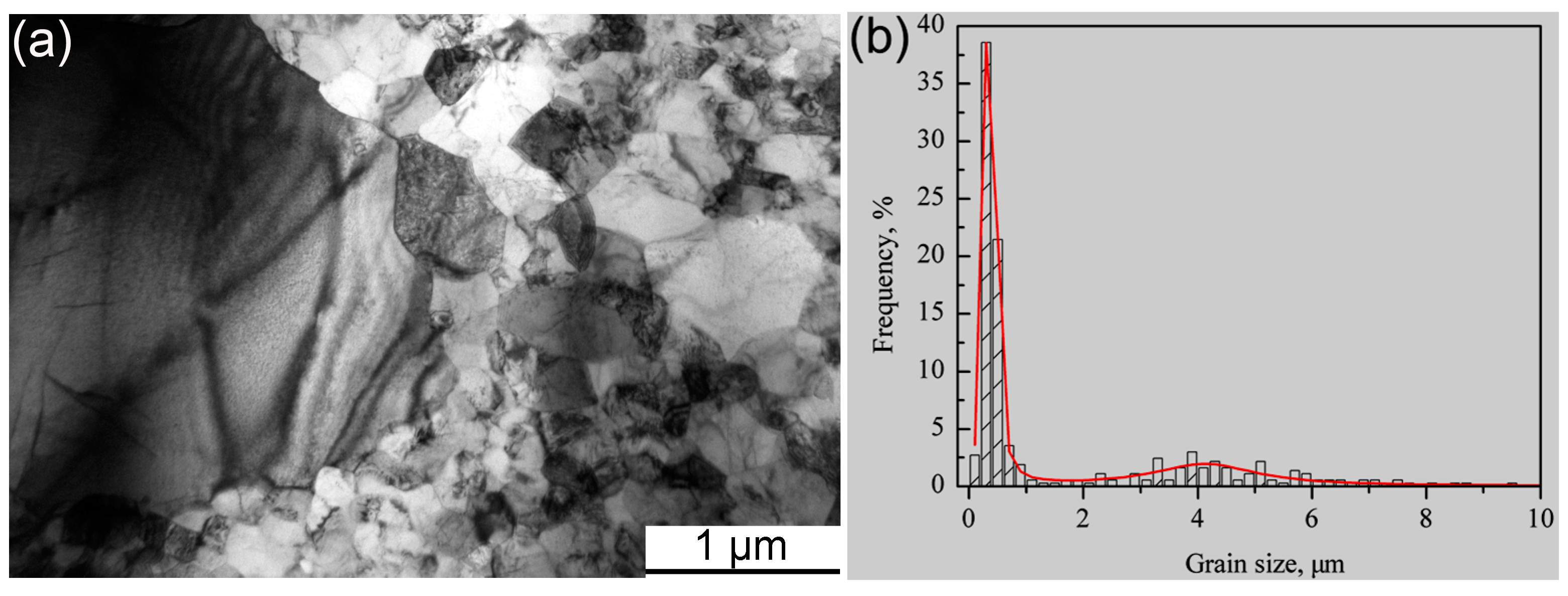
  • The particle sizes and morphologies of the MP, MX and ODS powders are different. The excellent refinement effect of ODS powders is attributed to the addition of hard Y2O3 and Ti powders acting as friction material during the mechanical alloying process.
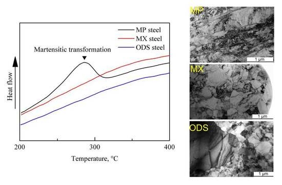
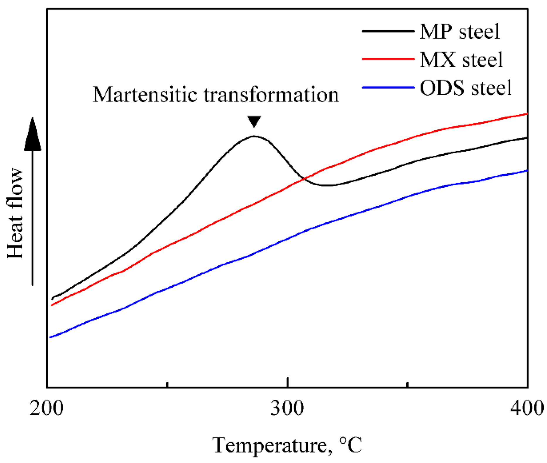
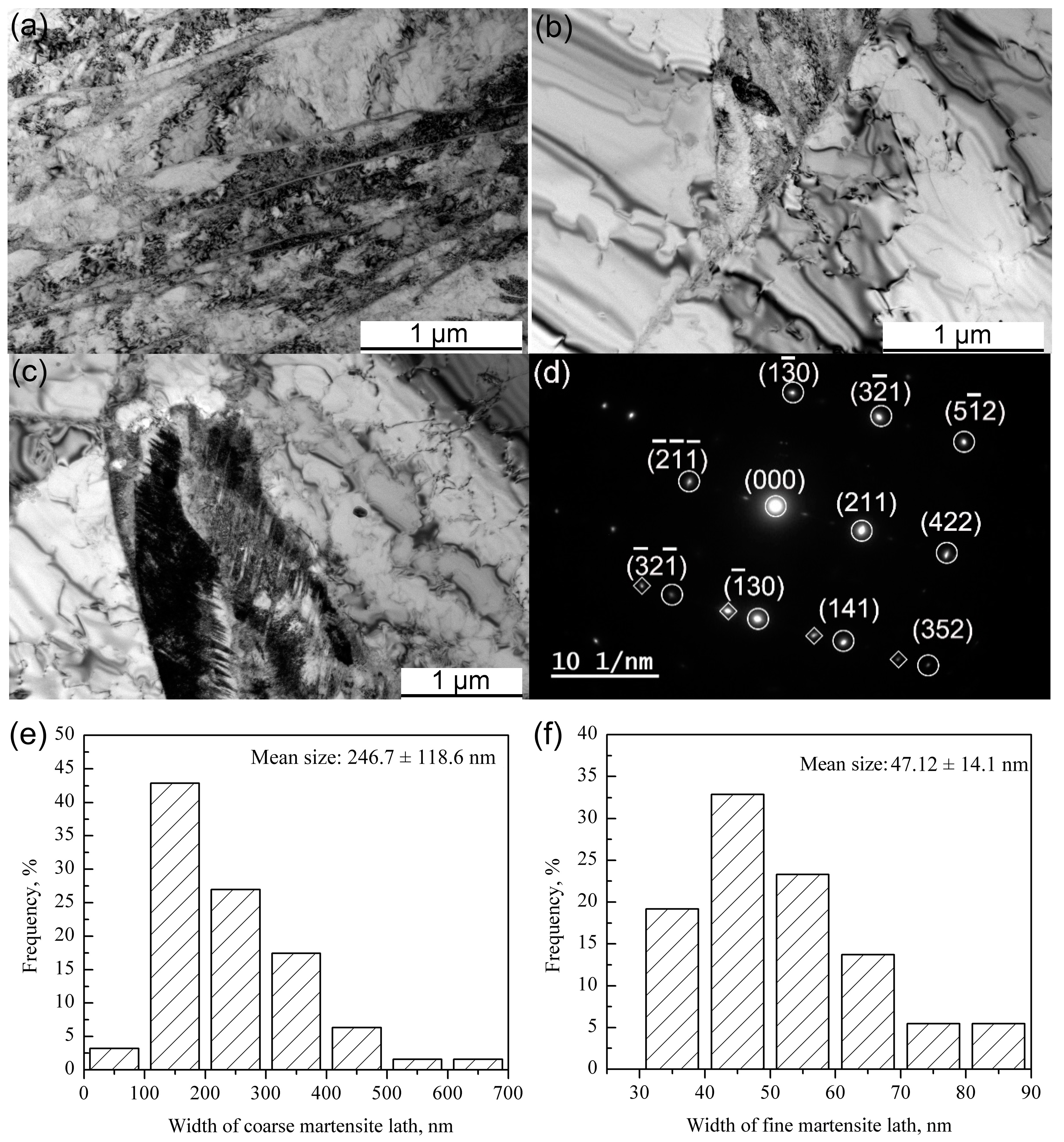
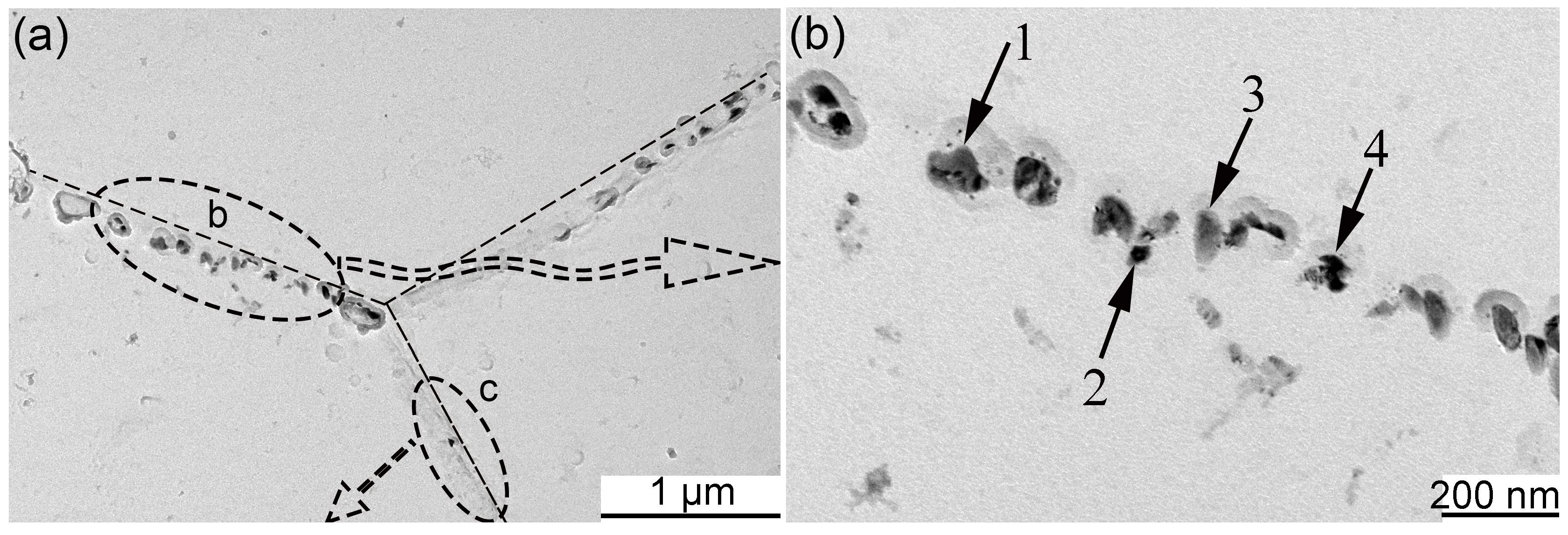
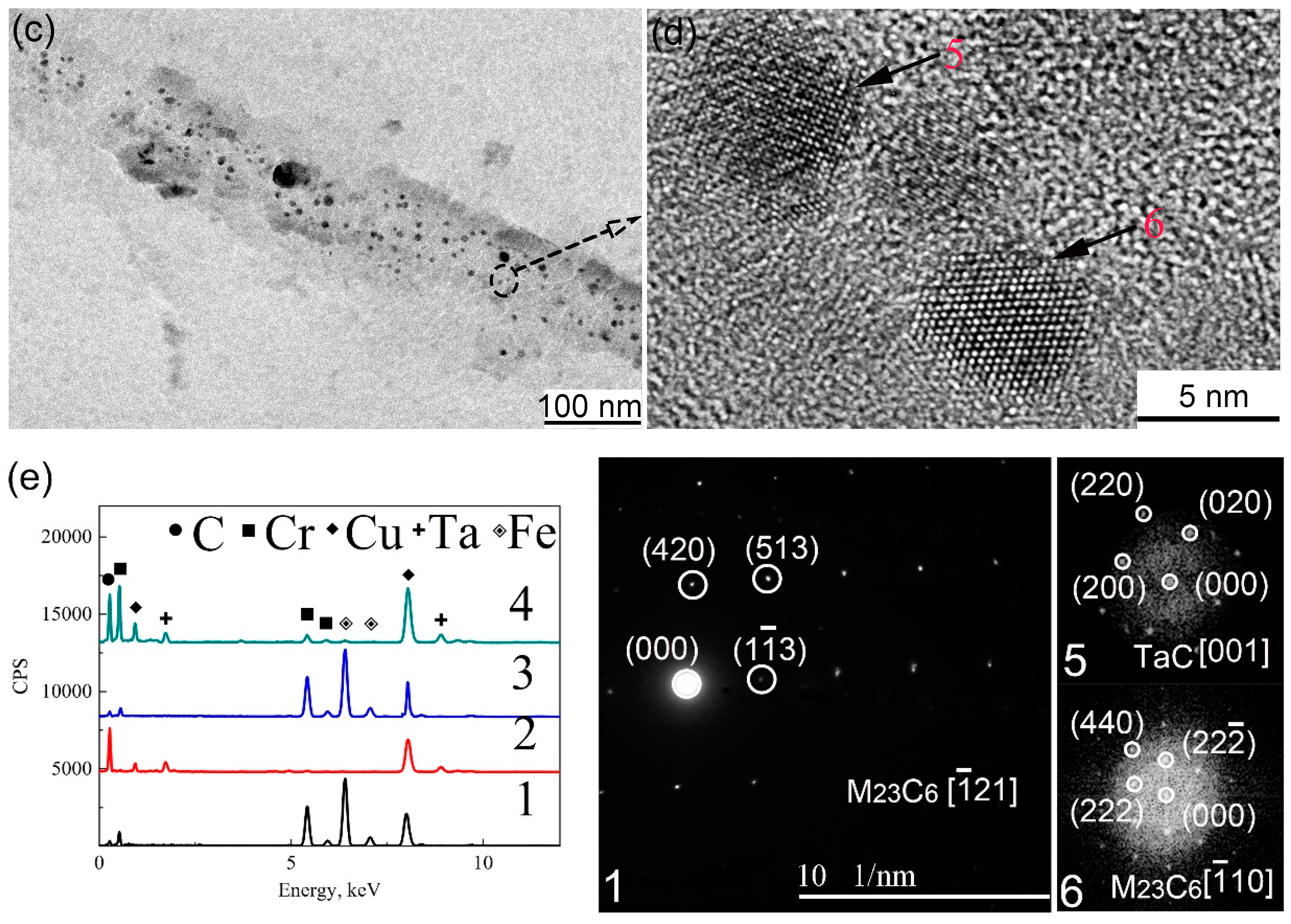
  • The generation of martensite lath in the MP steel is due to the large amounts of M23C6, which results in the local Cr depletion.
  • In the MX and ODS steel with Ti addition, no martensite transformation occurs during the fabrication process. C prefers to react with Ti since Ti possesses stronger affinity to C than Cr, which effectively hinder the precipitation of M23C6 and inhibit Cr depletion phenomenon. In addition, the long-range diffusion ability and uniform distribution of Ti contributes towards stabilizing the ferrite in the MX steel.
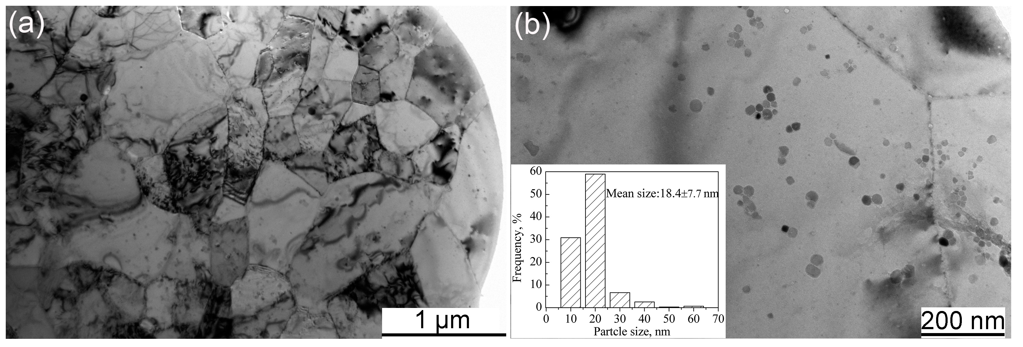
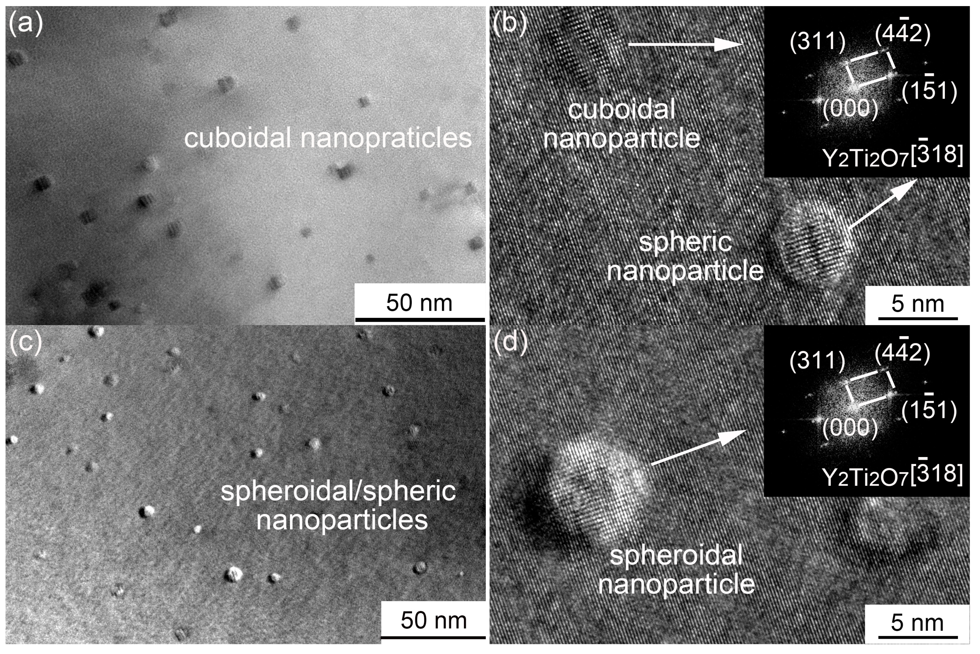
  • The diffusion of Y is limited in the matrix, which results in a heterogeneous distribution of Y-Ti-O nanoparticles in the MX steel.

Author Contributions

Q.Z. designed and drafted the manuscript; Z.M. revised the manuscript; L.Y. and H.L. performed the statistical analysis; Z.W. provided assistance for data acquisition and data analysis; Y.L. performed manuscript review; All authors read and approved the final manuscript.

Funding

This research was funded by National Natural Science Foundation of China (Granted Nos. 51474156 and U1660201) and the National Magnetic Confinement Fusion Energy Research Project (granted No. 2015GB119000).

Conflicts of Interest

The authors declare no conflicts of interest.

References

  1. Sornin, D.L.; Karch, A.; Logé, R.E. Competition between intragranular and intergranular deformation mechanisms in ODS ferritic steels during hot deformation at high strain rate. J. Mater. Sci. 2017, 9, 1–11. [Google Scholar] [CrossRef]
  2. Pimentel, G.; Capdevila, C.; Bartolomé, M.J.; Chao, J.; Serrano, M.; García-Junceda, A.; Campos, M.; Torralba, J.M.; Aldazábal, J. Advanced FeCrAl ODS steels for high-temperature structural applications in energy generation systems. Rev. Metall. 2012, 48, 303–316. [Google Scholar] [CrossRef] [Green Version]
  3. Sugino, Y.; Ukai, S.; Oono, N.; Hayashi, S.; Kaito, T.; Ohtsuka, S.; Masuda, H.; Taniguchi, S.; Sato, E. High temperature deformation mechanism of 15CrODS ferritic steels at cold-rolled and recrystallized conditions. J. Nucl. Mater. 2015, 466, 653–657. [Google Scholar] [CrossRef]
  4. Klimenkov, M.; Lindau, R.; Jäntsch, U.; Möslang, A. Effect of irradiation temperature on microstructure of ferritic-martensitic ODS steel. J. Nucl. Mater. 2017, 493, 426–435. [Google Scholar] [CrossRef]
  5. Robertson, C.; Panigrahi, B.K.; Balaji, S.; Kataria, S.; Serruys, Y.; Mathon, M.H.; Sundar, C.S. Particle stability in model ODS steel irradiated up to 100 dpa at 600 °C: TEM and nano-indentation investigation. J. Nucl. Mater. 2012, 426, 240–246. [Google Scholar] [CrossRef]
  6. Rogozhkin, S.V.; Aleev, A.A.; Zaluzhnyi, A.G.; Iskanderov, N.A.; Nikitin, A.A.; Vladimirov, P.; Lindau, R.; Möslang, A. Atom probe tomography of nanoscaled features of oxide-dispersion-strengthened ODS Eurofer steel in the initial state and after neutron irradiation. Phys. Met. Metallogr. 2012, 113, 98–105. [Google Scholar] [CrossRef]
  7. Wharry, J.P.; Swenson, M.J.; Yano, K.H. A review of the irradiation evolution of dispersed oxide nanoparticles in the bcc Fe-Cr system: Current understanding and future directions. J. Nucl. Mater. 2017, 486, 11–20. [Google Scholar] [CrossRef]
  8. Alinger, M.J.; Odette, G.R.; Hoelzer, D.T. On the role of alloy composition and processing parameters in nanocluster formation and dispersion strengthening in nanostuctured ferritic alloys. Acta Mater. 2009, 57, 392–406. [Google Scholar] [CrossRef]
  9. Klimiankou, M.; Lindau, R.; Moslang, A. Energy-filtered TEM imaging and EELS study of ODS particles and Argon-filled cavities in ferritic–martensitic steels. Micron 2005, 36, 1–8. [Google Scholar] [CrossRef] [PubMed]
  10. Pasebani, S.; Charit, I. Effect of alloying elements on the microstructure and mechanical properties of nanostructured ferritic steels produced by spark plasma sintering. J. Alloys Compd. 2014, 599, 206–211. [Google Scholar] [CrossRef]
  11. Ramtani, S.; Dirras, G.; Bui, H.Q. A bimodal bulk ultra-fine-grained nickel: Experimental and micromechanical investigations. Mech. Mater. 2010, 42, 522–536. [Google Scholar] [CrossRef]
  12. Srinivasarao, B.; Oh-ishi, K.; Ohkubo, T.; Mukai, T.; Hono, K. Synthesis of high-strength bimodally grained iron by mechanical alloying and spark plasma sintering. Scr. Mater. 2008, 58, 759–762. [Google Scholar] [CrossRef]
  13. Cao, G.H.; Peng, Y.F.; Liu, N.; Li, X.; Lei, Z.S.; Ren, Z.M.; Gerthsen, D.; Russell, A.M. Formation of a bimodal structure in ultrafine Ti–Fe–Nb alloys with high-strength and enhanced ductility. Mater. Sci. Eng. A 2014, 609, 60–64. [Google Scholar] [CrossRef]
  14. Park, H.W.; Shimojima, K.; Sugiyama, S.; Komine, H.; Yanagimoto, J. Microstructural evolution and formation mechanism of bimodal structure of 0.2% carbon steel subjected to the heavy-reduction controlled rolling process. Mater. Sci. Eng. A 2015, 624, 203–212. [Google Scholar] [CrossRef] [Green Version]
  15. Zhang, F.; Liu, Z.; Zhou, J. Molecular dynamics simulation of micro-mechanical deformations in polycrystalline copper with bimodal structures. Mater. Lett. 2016, 183, 261–264. [Google Scholar] [CrossRef]
  16. Zhang, Z.; Orlov, D.; Vajpai, S.K.; Tong, B.; Ameyama, K. Importance of bimodal structure topology in the control of mechanical properties of a stainless steel. Adv. Eng. Mater. 2015, 17, 791–795. [Google Scholar] [CrossRef]
  17. Zhu, L.; Lu, J. Modelling the plastic deformation of nanostructured metals with bimodal grain size distribution. Int. J. Plast. 2012, 30–31, 166–184. [Google Scholar] [CrossRef]
  18. Liu, F.; Liu, Y.; Wu, H.; Fang, J.; Zhao, D.; Zhang, L.; Liu, D. Bi-modal microstructure in a powder metallurgical ferritic steel. Trans. Nonferr. Met. Soc. China 2012, 22, 330–334. [Google Scholar] [CrossRef]
  19. Srinivasarao, B.; Oh-ishi, K.; Ohkubo, T.; Hono, K. Bimodally grained high-strength Fe fabricated by mechanical alloying and spark plasma sintering. Acta Mater. 2009, 57, 3277–3286. [Google Scholar] [CrossRef]
  20. Auger, M.A.; Castro, V.D.; Leguey, T.; Muñoz, A.; Pareja, R. Microstructure and mechanical behavior of ODS and non-ODS Fe–14Cr model alloys produced by spark plasma sintering. J. Nucl. Mater. 2013, 436, 68–75. [Google Scholar] [CrossRef] [Green Version]
  21. Boulnat, X.; Perez, M.; Fabregue, D.; Douillard, T.; Mathon, M.H.; Carlan, Y.D. Microstructure evolution in nano-reinforced ferritic steel processed by mechanical alloying and spark plasma sintering. Metall. Mater. Trans. A 2014, 45, 1485–1497. [Google Scholar] [CrossRef]
  22. Dadé, M.; Malaplate, J.; Garnier, J.; Geuser, F.D.; Barcelo, F.; Wident, P.; Deschamps, A. Influence of microstructural parameters on the mechanical properties of oxide dispersion strengthened Fe-14Cr steels. Acta Mater. 2017, 127, 165–177. [Google Scholar] [CrossRef]
  23. Mouawad, B.; Boulnat, X.; Fabrègue, D.; Perez, M.; Carlan, Y.D. Tailoring the microstructure and the mechanical properties of ultrafine grained high strength ferritic steels by powder metallurgy. J. Nucl. Mater. 2015, 465, 54–62. [Google Scholar] [CrossRef]
  24. Suryanarayana, C. Mechanical alloying and milling. Prog. Mater. Sci. 2001, 46, 1–184. [Google Scholar] [CrossRef]
  25. West, M.K. Processing and Characterization of Oxide Dispersion Strengthened 14YWT Ferritic Alloys. Ph.D. Thesis, University of Tennessee, Knoxville, TN, USA, 2006. [Google Scholar]
  26. Nagini, M.; Vijay, R.; Ramakrishna, M.; Reddy, A.V.; Sundararajan, G. Influence of the duration of high energy ball milling on the microstructure and mechanical properties of a 9Cr oxide dispersion strengthened ferritic–martensitic steel. Mater. Sci. Eng. A 2015, 620, 490–499. [Google Scholar] [CrossRef]
  27. Brocq, M.; Radiguet, B.; Breton, J.M.; Cuvilly, F.; Pareige, P.; Legendre, F. Nanoscale characterisation and clustering mechanism in an Fe–Y2O3 model ODS alloy processed by reactive ball milling and annealing. Acta Mater. 2010, 58, 1806–1814. [Google Scholar] [CrossRef]
  28. Magini, M.; Iasonna, A.; Padella, F. Ball milling: An experimental support to the energy transfer evaluated by the collision model. Scr. Mater. 1996, 34, 13–19. [Google Scholar] [CrossRef]
  29. Zhang, D.L. Processing of advanced materials using high-energy mechanical milling. Prog. Mater. Sci. 2004, 49, 537–560. [Google Scholar] [CrossRef]
  30. Ustinovshikov, Y.; Pushkarev, B.; Igumnov, I. Fe-rich portion of the Fe-Cr phase diagram: Electron microscopy study. J. Mater. Sci. 2002, 37, 2031–2042. [Google Scholar] [CrossRef]
  31. Oksiuta, Z.; Olier, P.; Carlan, Y.D.; Baluc, N. Development and characterisation of a new ODS ferritic steel for fusion reactor application. J. Nucl. Mater. 2009, 393, 114–119. [Google Scholar] [CrossRef]
  32. Olier, P.; Couvrat, M.; Cayron, C.; Lochet, N.; Chaffron, L. Incidence of mechanical alloying contamination on oxides and carbides formation in ODS ferritic steels. J. Nucl. Mater. 2013, 442, S106–S111. [Google Scholar] [CrossRef]
  33. Olier, P.; Malaplate, J.; Mathon, M.H.; Nunes, D.; Hamon, D.; Toualbi, L.; Carlan, Y.D.; Chaffron, L. Chemical and microstructural evolution on ODS Fe–14CrWTi steel during manufacturing stages. J. Nucl. Mater. 2012, 428, 40–46. [Google Scholar] [CrossRef]
  34. London, A.J.; Santra, S.; Amirthapandian, S.; Panigrahi, B.K.; Sarguna, R.M.; Balaji, S.; Vijay, R.; Sundar, C.S.; Lozano-Perez, S.; Grovenor, C.R.M. Effect of Ti and Cr on dispersion, structure and composition of oxide nano-particles in model ODS alloys. Acta Mater. 2015, 97, 223–233. [Google Scholar] [CrossRef]
  35. Sakasegawa, H.; Chaffron, L.; Legendre, F.; Boulanger, L.; Cozzika, T.; Brocq, M.; Carlan, Y.D. Correlation between chemical composition and size of very small oxide particles in the MA957 ODS ferritic alloy. J. Nucl. Mater. 2009, 384, 115–118. [Google Scholar] [CrossRef]
  36. Tamura, M.; Sakasegawa, H.; Shiba, K.; Tanigawa, H.; Shinozuka, K.; Esaka, H. Decomposition of Y2Ti2O7 Particles in 8 Pct Cr Oxide-Dispersion-Strengthened Martensitic Steel during Tempering. Metall. Mater. Trans. A 2011, 42, 2176–2188. [Google Scholar] [CrossRef]
  37. Zhang, H.; Huang, Y.; Ning, H.; Williams, C.A.; London, A.J.; Dawson, K.; Hong, Z.; Gorley, M.J.; Grovenor, C.R.M.; Tatlock, G.J.; et al. Processing and microstructure characterisation of oxide dispersion strengthened Fe–14Cr–0.4Ti–0.25Y2O3 ferritic steels fabricated by spark plasma sintering. J. Nucl. Mater. 2015, 464, 61–68. [Google Scholar] [CrossRef] [Green Version]
  38. Zhong, S.Y.; Ribis, J.; Lochet, N.; Carlan, Y.D.; Klosek, V.; Ji, V.; Mathon, M.H. The Effect of Y/Ti Ratio on Oxide Precipitate Evolution in ODS Fe-14 Wt Pct Cr Alloys. Metall. Mater. Trans. A 2015, 46, 1413–1418. [Google Scholar] [CrossRef]
  39. Zhao, Q.; Yu, L.; Liu, Y.; Huang, Y.; Ma, Z.; Li, H.; Wu, J. Microstructure and tensile properties of a 14Cr ODS ferritic steel. Mater. Sci. Eng. A 2017, 680, 347–350. [Google Scholar] [CrossRef]
  40. Kim, J.K.; Lee, B.J.; Lee, B.H.; Kim, Y.H.; Kim, K.Y. Intergranular segregation of Cr in Ti-stabilized low-Cr ferritic stainless steel. Scr. Mater. 2009, 61, 1133–1136. [Google Scholar] [CrossRef]
  41. Wang, S.B.; Liu, J.Z.; Qi, Q.; Chang, X.F.; Gao, S.; Zhang, W.; Wang, P. Precipitate formations with self-adaptive elemental diffusion and segregation in T92 steel. J. Alloys Compd. 2017, 693, 264–278. [Google Scholar] [CrossRef]
  42. Zhu, J.; Yan, X.; Liu, Y. Lath martensite in 1.4% C ultra-high carbon steel and its grain size effect. Mater. Sci. Eng. A 2004, 385, 440–444. [Google Scholar]
  43. Krauss, G.; Marder, A.R. The morphology of martensite in iron alloys. Metall. Trans. 1971, 2, 2343–2357. [Google Scholar] [CrossRef]
  44. Inoue, A.; Tomioka, H.; Masumoto, T. Microstructure and mechanical properties of metastable lath martensite wires in the Fe-Ni-Cr-Al-C system produced by melt spinning in rotating water. J. Mater. Sci. 1985, 20, 2603–2613. [Google Scholar] [CrossRef]
  45. Morito, S.; Saito, H.; Ogawa, T.; Furuhara, T.; Maki, T. Effect of austenite grain size on the morphology and crystallography of lath martensite in low carbon steels. ISIJ Int. 2005, 45, 91–94. [Google Scholar] [CrossRef]
  46. Fu, C.L.; Krcmar, M.; Painter, G.S.; Chen, X.Q. Vacancy mechanism of high oxygen solubility and nucleation of stable oxygen-enriched clusters in Fe. Phys. Rev. Lett. 2007, 99, 225502. [Google Scholar] [CrossRef] [PubMed]
  47. Murali, D.; Panigrahi, B.K.; Valsakumar, M.C.; Chandra, S.; Sundar, C.S.; Raj, B. The role of minor alloying elements on the stability and dispersion of yttria nanoclusters in nanostructured ferritic alloys: An ab initio study. J. Nucl. Mater. 2010, 403, 113–116. [Google Scholar] [CrossRef]
  48. Peng, T.; Zhang, C.; Yang, Z.G.; Hiroyuki, T. Evolution and coarsening of carbides in 2. 25Cr-1Mo steel weld metal during high temperature tempering. J. Iron Steel Res. Int. 2010, 17, 74–78. [Google Scholar]
  49. Zhang, C.; Cui, L.; Liu, Y.; Liu, C.; Li, H. Microstructures and mechanical properties of friction stir welds on 9% Cr reduced activation ferritic/martensitic steel. J. Mater. Sci. Technol. 2018, 34, 756–766. [Google Scholar] [CrossRef]
Figure 1. Schematic graph of the experimental procedures. Three model powders defined as MP powders (milled pre-alloyed powders), MX powders (50 wt.% MP powders + 50 wt.% (oxide dispersion strengthened) ODS powders) and ODS powders (alloyed pre-alloyed powders with the addition of Ti and Y2O3). SPS: spark plasma sintering.
Metals 08 00802 g001
Figure 2. Optical microscope (OM) images of polished and etched powders at different magnifications: (a,b) pre-alloyed; (c,d) MP; (e,f) MX; (g,h) ODS.
Metals 08 00802 g002
Figure 3. Particle size distribution of different powders: (a) pre-alloyed; (b) MP; (c) MX; (d) ODS.
Metals 08 00802 g003
Figure 4. SEM images of polished and etched powders: (a) MP; (b) MX; (c) ODS.
Metals 08 00802 g004
Figure 5. OM images of polished and etched samples: (a) MP; (b) MX; (c) ODS.
Metals 08 00802 g005
Figure 6. Scanning electron microscope (SEM) images of polished and etched samples at different magnifications: (a,b) MP; (c,d) MX; (e,f) ODS.
Metals 08 00802 g006aMetals 08 00802 g006b
Figure 7. Differential scanning calorimeter (DSC) curves of the consolidated steels.
Metals 08 00802 g007
Figure 8. Transmission electron microscope (TEM) microstructure of the MP steel: (a) the coarse martensite lath; (b) grain boundary and the martensite lath; (c) fine martensite lath and (d) the corresponding selected area electron diffraction (SAED) pattern; width distribution of (e) coarse and (f) fine martensite lath.
Metals 08 00802 g008
Figure 9. (a) TEM microstructure of the MX steel; (b) particles in the micro-sized grain.
Metals 08 00802 g009
Figure 10. (a) TEM microstructure and (b) grain size distribution of the ODS steel.
Metals 08 00802 g010
Figure 11. Secondary phases in the MP steel: (ac) carbides distributed along grain boundary; (d) high resolution transmission electron microscope (HRTEM) image of nano-sized carbide; (e) EDS, SAED, and fast fourier transform (FFT) patterns of the marked carbides.
Metals 08 00802 g011aMetals 08 00802 g011b
Figure 12. Secondary phases in the MX steel: (a) carbides and the selected area electron diffraction (SAED) pattern of particle 1; (b) EDS results of the carbides marked in (a); (c) particles distributed in a small grain (several hundred nanometers); (d) SAED pattern of the marked area in (c).
Metals 08 00802 g012
Figure 13. Nanoparticles in the MX steel: (a) TEM image of cuboidal nanoparticles; (b) HRTEM image of cuboidal and spheric nanoparticles with the corresponding FFT pattern; (c) TEM image of spheroidal/spheric nanoparticles; (d) HRTEM image of spheroidal nanoparticle with the corresponding FFT pattern.
Metals 08 00802 g013
Figure 14. Secondary phases in the ODS steel: (a) M23C6 particles; (b) distribution of nanoparticles; (ce) HRTEM images of nanoparticles and the corresponding FFT patterns.
Metals 08 00802 g014

