Article

High-Temperature Tempered Martensite Embrittlement in Quenched-and-Tempered Offshore Steels

1
Department of Materials Science and Engineering, National Taiwan University, Roosevelt Road, Taipei 10617, Taiwan
2
Iron and Steel R&D Department, China Steel Corporation, Chung Kang Road, Kaohsiung 81233, Taiwan
*
Author to whom correspondence should be addressed.
Metals 2017, 7(7), 253; https://doi.org/10.3390/met7070253
Submission received: 31 May 2017 / Revised: 23 June 2017 / Accepted: 3 July 2017 / Published: 6 July 2017
(This article belongs to the Special Issue Bainite and Martensite: Developments and Challenges)

Abstract

:
Embrittlement induced by high-temperature tempering was investigated in two quenched-and-tempered offshore steels. Electron backscattering diffraction and analysis of Kernel average misorientation were applied to study the coalescence of martensite; transmission Kikuchi diffraction coupled with compositional mapping was used to characterize the martensite/austenite (M/A) phases. It is suggested that the formation of lenticular martensite along prior austenite grain boundaries or packet boundaries primarily explains the embrittlement in conventional S690Q steel, which has a higher carbon content. This embrittlement can be cured by additional heat treatment to decompose martensite into ferrite and cementite. In a newly designed NiCu steel with reduced carbon content, new lath martensite formed along interlath or inter-block boundaries of prior martensite. This microstructure is less detrimental to the impact toughness of the steel.

Graphical Abstract

1. Introduction

Steels with higher strength are in demand for offshore construction due to their light weight and lower material and transportation costs. One such steel is S690Q steel plate, which is recognized as a strong, tough, and highly weldable steel for offshore structures [1]. The production process of such steels usually involves quenching to transform austenite into martensite, followed by proper tempering to obtain the required properties. This quenching-and-tempering thermal cycle also occurs during multi-pass welding of these materials. Hence, the sensitivity of a material’s toughness to tempering temperature is critical for offshore steels.
It has long been known that high strength martensitic steels, which are heat-treated to reach the optimum balance of strength, ductility, and toughness, are susceptible to embrittlement during tempering [2]. In the low temperature range of 230 °C to 370 °C, tempering can lead to brittleness due to strain aging, known as blue brittleness because of the blue surface scales that form [3]. Embrittlement can also occur when martensitic steel is heat treated in the temperature range of 370 °C to 575 °C. Temper embrittlement occurs during the holding or slow cooling of alloy steels previously tempered above 600 °C. This embrittlement is believed to be caused by the segregation of phosphorus, sulfur, tin, or other impurities at prior austenite grain boundaries [4,5]. Tempered martensite embrittlement occurs during tempering of as-quenched alloy steels in the range of 370 °C to 575 °C. It was originally suggested that the thermal instability of retained austenite during tempering produced embrittlement due to its decomposition to interlath films of M3C carbides [6,7,8]. However, it was later found that embrittlement is concurrent with the interlath precipitation of cementite during initial tempering and the consequent mechanical instability of interlath films of retained austenite during subsequent loading [9]. Also, another study suggested that tempered martensite embrittlement is controlled by coarsening of the comparatively larger amount of interlath cementite resulting from thermal decomposition of the interlath retained austenite [10]. It is generally recognized that the occurrence of tempered martensite embrittlement cannot be attributed to a single mechanism, such as interlath carbide precipitation, decomposition of retained austenite, or impurity segregation, and that it is almost certainly due to a combination of several factors.
Temper embrittlement and tempered martensite embrittlement are usually discussed in relation to medium-carbon alloyed steels. The current work describes embrittlement due to tempering at the high temperature range of 600 °C to 780 °C in S690Q and a newly designed steel, both of which are low-carbon steels. They show strong contrasts in sensitivity to this embrittlement after high-temperature tempering. The results and discussion in this work should be useful in the alloy design of advanced offshore steels.

2. Materials and Methods

The chemical compositions of the studied steels are listed in Table 1. One is the commercially named S690Q steel, which is quenched-and-tempered (Q&T) martensitic steel. The other, named NiCu steel in this work, is a new Q&T steel having lower carbon content but higher nickel and copper contents. Both steels were produced by vacuum induction melting (VIM). The ingots were held at 1200 °C for 2 h and then cast into 160 mm-thick slabs, followed by air cooling. The slabs were thermo-mechanically processed and directly quenched in a pirate mill at China Steel Corporation. The slabs were reheated at 1200 °C for 1 h, hot rolled into 30 mm-thick plates, and then directly water quenched. The start-rolling temperature was about 1100 °C, and the finish-rolling temperature was about 800 °C. The as-quenched steels were cut into several 11 mm × 11 mm square rods. These rods were tempered at 600 °C, 660 °C, 720 °C, and 780 °C for 1 h before being quenched in a salt bath. After the heat treatments, the rods were machined into specimens for Charpy impact tests (Model IT406, Tinius Olsen, Redhill, UK). The notches were located on the plane normal to the transverse direction (TD). The testing temperature was −40 °C.
As-quenched and tempered specimens were investigated by electron backscattering diffraction (EBSD) and transmission Kikuchi diffraction (TKD) in a scanning electron microscope (SEM). EBSD experiments were conducted with an FEI NOVA SEM (FEI, Hillsboro, OR, USA) equipped with a TSL EBSD detector, and the results were processed in the Orientation Imaging Microscopy (OIMTM) software (version 6.2, EDAX, Mahwah, NJ, USA). TKD experiments coupled with X-ray energy-dispersive spectrum (EDS) mapping were conducted with a JSM 7800F PRIME SEM (JEOL, Tokyo, Japan) equipped with an Oxford Nordlys EBSD detector and an Oxford X-Max50 EDS detector. The TKD results were processed in the Aztec 3.0 system and the HKL Channel 5 software. The fine structures of the M/A phase were confirmed with an FEI TECNAI F20 transmission electron microscope (TEM). Specimens for TEM, EBSD, and TKD were prepared by electrochemical polishing at 5 °C in an electrolyte mixture of 5% perchloric acid, 15% glycerol, and 80% alcohol (in vol %).

3. Results

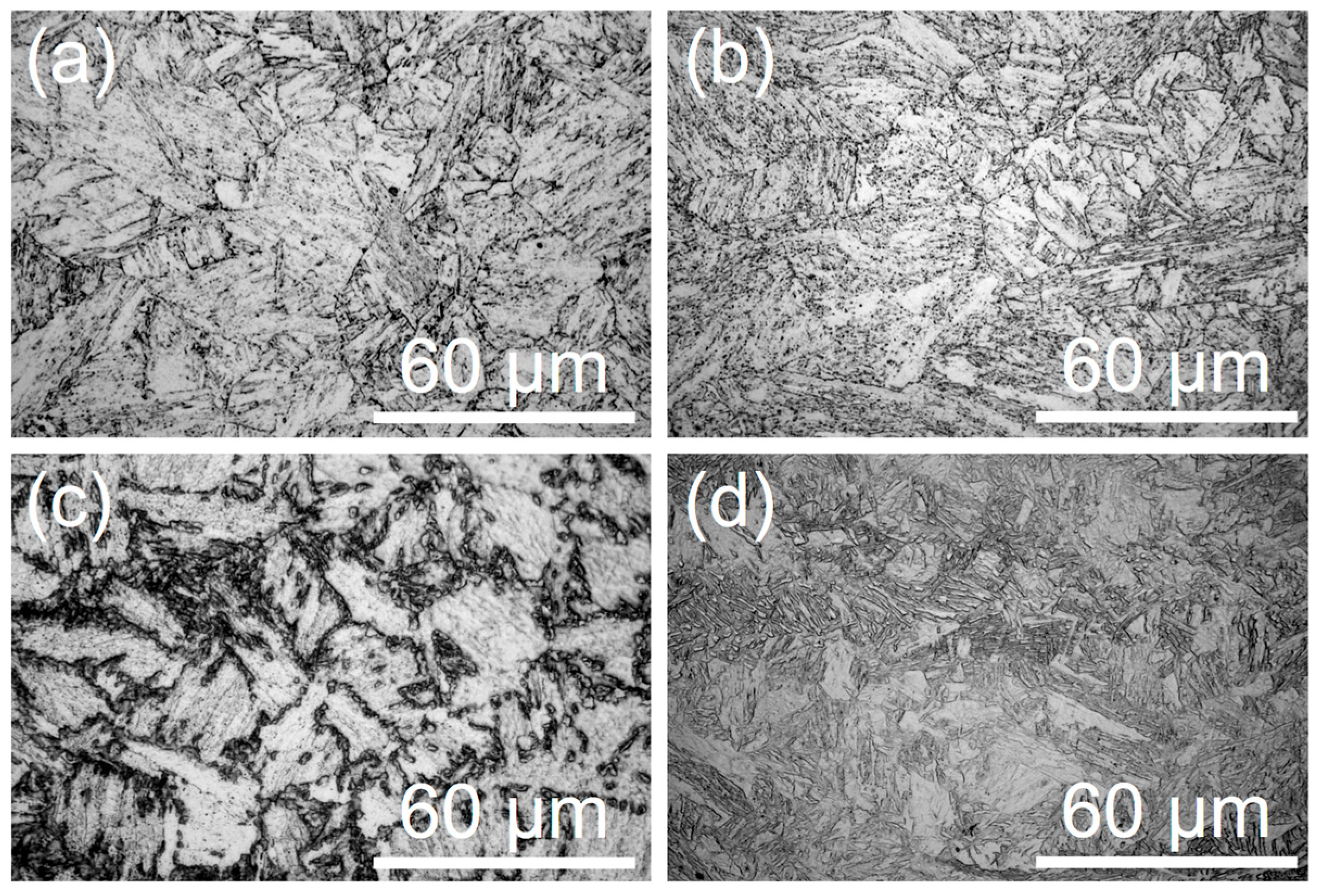
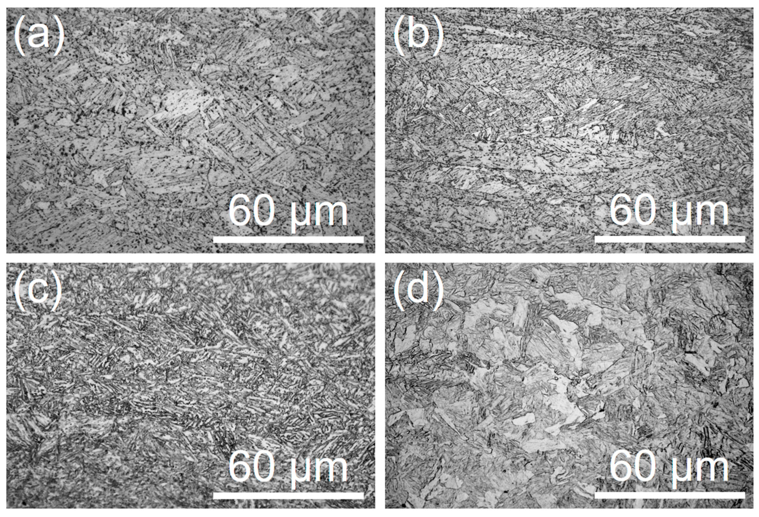
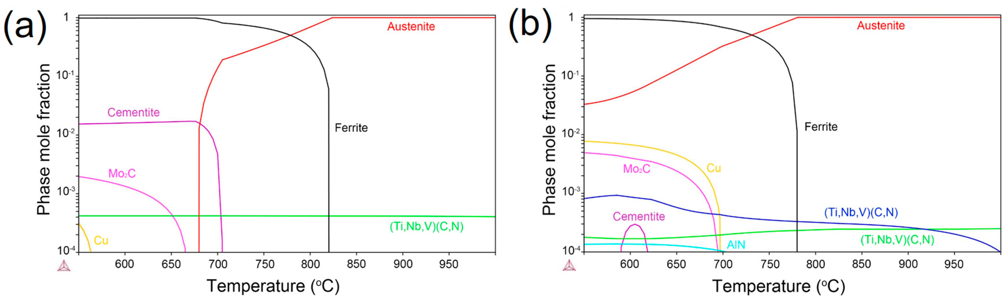
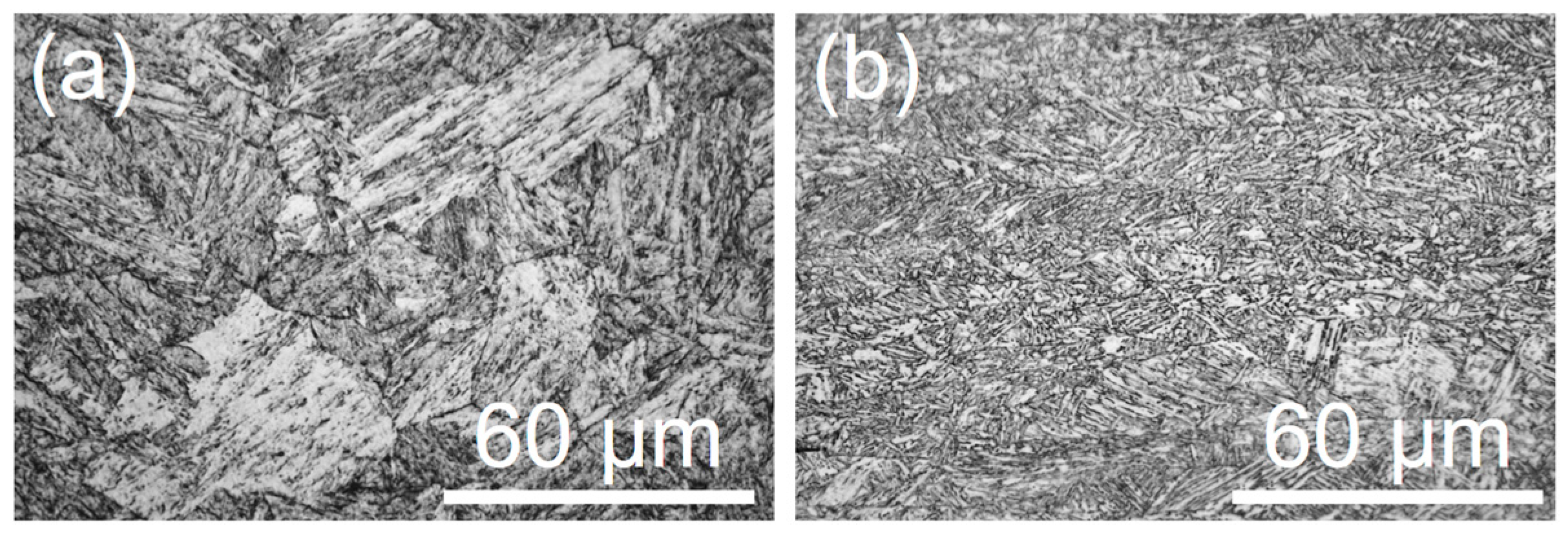
3.1. Quenched and Tempered Microstructure

The microstructures of the as-quenched S690Q and NiCu steels are shown in Figure 1a,b, respectively. Although both steels were thermo-mechanically processed under similar parameters, the S690Q steel had equaixed prior austenite, and the NiCu steel had pancaked prior austenite. The retarded recrystallization in NiCu may have resulted from the higher contents of microalloying elements, as listed in Table 1. After water-quenching, the microstructures were lath martensite in both steels.
The microstructures in the S690Q and NiCu steels after tempering at different temperatures are shown in Figure 2 and Figure 3, respectively. When the tempering temperature was low, the quenched and tempered states exhibited no significant differences in microstructure, as shown in Figure 2a,b and Figure 3a,b. After tempering at 720 °C, island-like micro-phases decorated the prior austenite grain boundaries in S690Q steel, as shown in Figure 2c. Tempering at 780 °C produced a microstructure of new martensite mixed with ferrite, as shown in Figure 2d. The new martensite resulted from martensitic transformation from reverted austenite, and the ferrite formed by coalescence of old martensite. Also, the micro-phases in S690Q steel tempered at 720 °C were likely martensite, probably M/A phases. However, the fine structure was not clear under an optical microscope.
In NiCu steel tempered at 720 °C, micro-phases formed along the interlath boundaries of martensite, as shown in Figure 3c. However, the fine structure could not be clearly observed under an optical microscope. After tempering at 780 °C, no trace of pancaked prior austenite grain boundaries was visible in NiCu steel, as shown in Figure 3d. In this case, the tempering temperature was so high that the microstructure became almost fully austenite. Hence, the reverted equaixed austenite eliminated the traces of pancaked prior austenite that formed during the thermo-mechanical process.

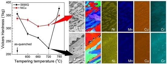
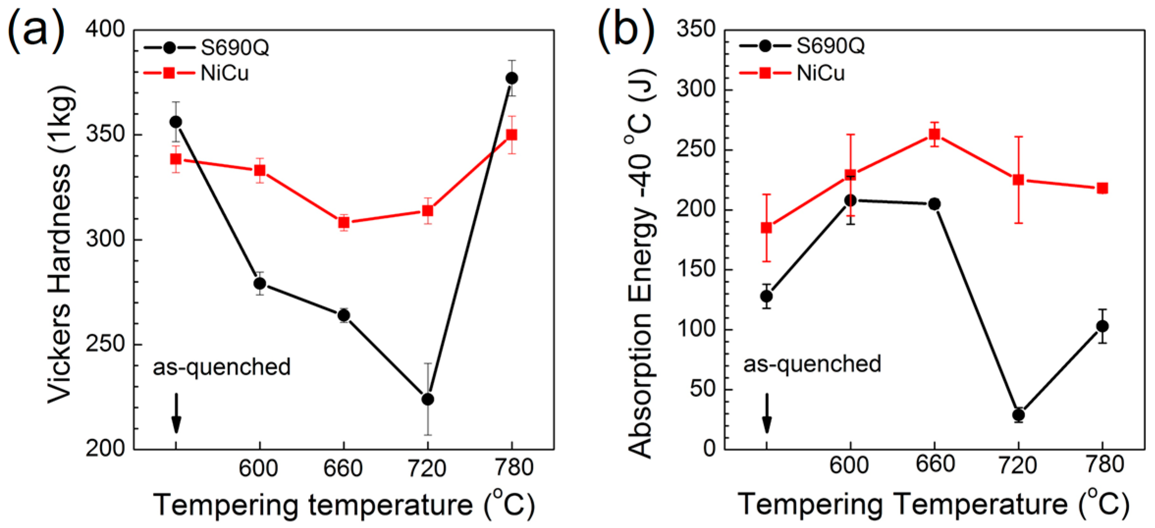
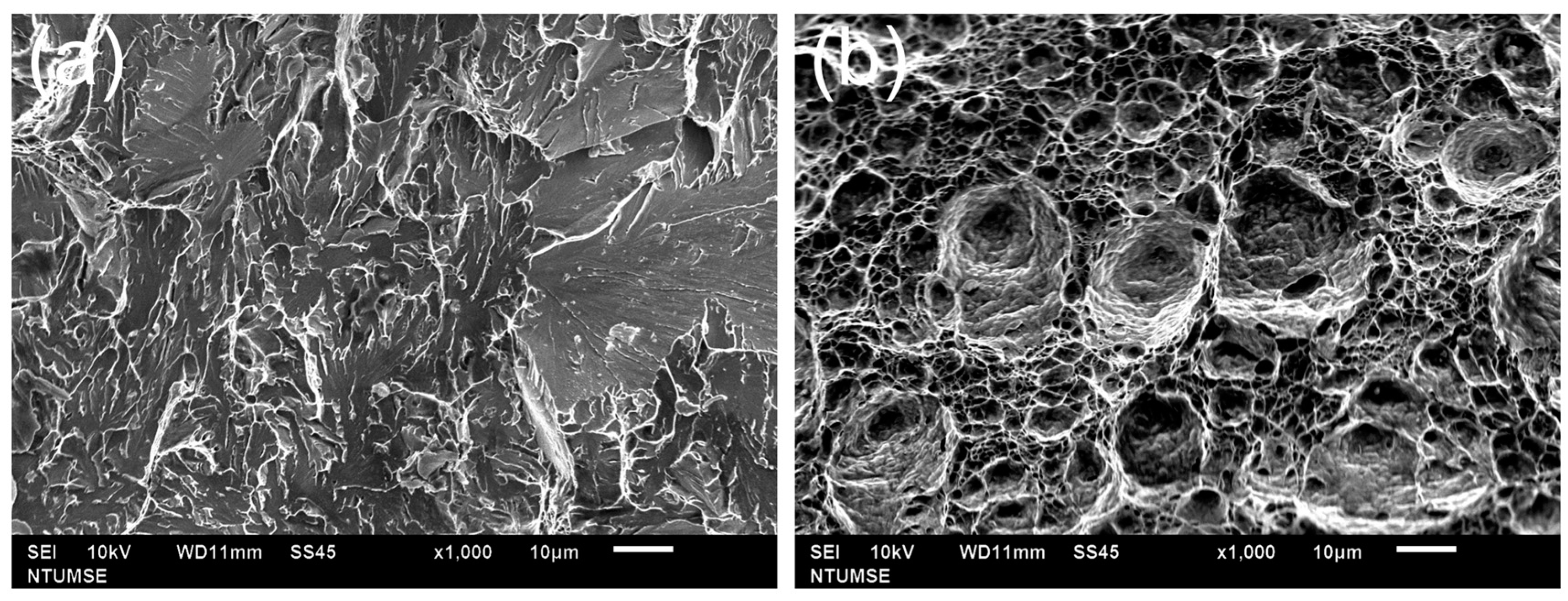
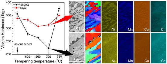
3.2. Mechanical Properties of Offshore Steels

Figure 4a shows the variation in Vickers hardness as a function of tempering temperature for both offshore steels. When tempering at low temperature, supersaturated carbon solutes partitioned into cementite, and, moreover, density of dislocation in martensite also decreased. Both factors caused the decrease in hardness of tempered martensite. As tempering temperature increased, the hardness of S690Q steel significantly decreased. However, tempering at 780 °C and quenching resulted in a large fraction of new martensite, and hardness increased to the level of the as-quenched state. In contrast, the decrease in hardness due to tempering can be mostly offset by precipitation hardening of copper in the NiCu steel. Hence, the hardness decreased slowly with increasing tempering temperature in the NiCu steel. Tempering at 600 °C for 1 h produced a yield strength of about 780 MPa and a total elongation of about 20% for S690Q steel. However, tempering at 660 °C for 1 h produced a yield strength of about 850 MPa and a total elongation of about 20% for NiCu steel. Both of them are well above the Norsok specification for the S690Q steel plate.
The absorbed energies of impact toughness at −40 °C are shown in Figure 4b for the two steels. The NiCu steel had better toughness performance. It was also found that toughness improved little, despite the elimination of pancaked prior austenite by manual quenching. Hence, the higher toughness of NiCu steel can be ascribed to its low carbon content. In most cases, tempering can improve the impact toughness of both steels. However, it is interesting that tempering at 720 °C and quenching greatly reduced the toughness of S690Q steel. The absorbed energy was only about 30 J when tested at −40 °C. In contrast, this detrimental effect was not dramatic in NiCu steel tempered at 720 °C or 780 °C. Based on the Norsok standard [1], the required impact toughness at −40 °C for 690 MPa-grade offshore steels is 100 J.
Figure 5 presents fractographs of the two steels tempered at 720 °C after the impact toughness tests at −40 °C. Consistent with the low toughness, the fractured surface of the S690Q steel revealed a brittle fracture with river cleavages. The fracture in NiCu steel was identified as ductile behavior, as indicated by the dimples.

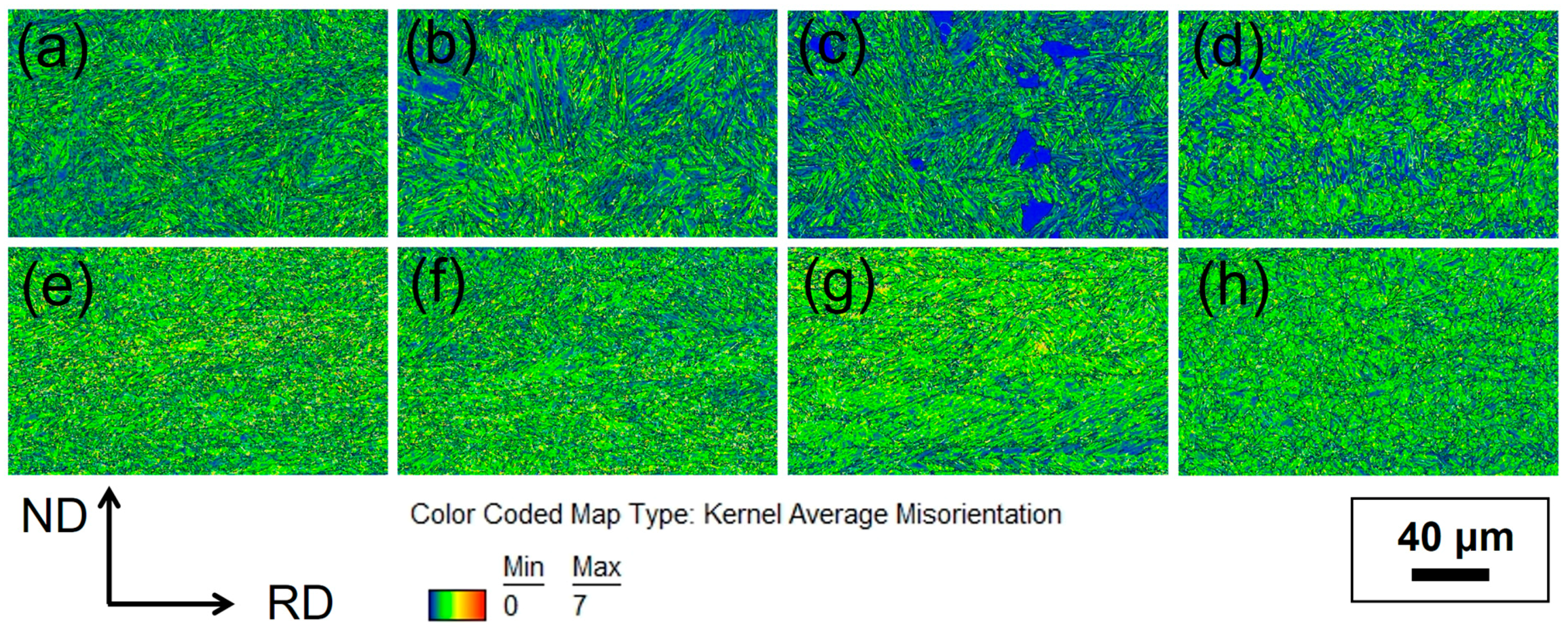
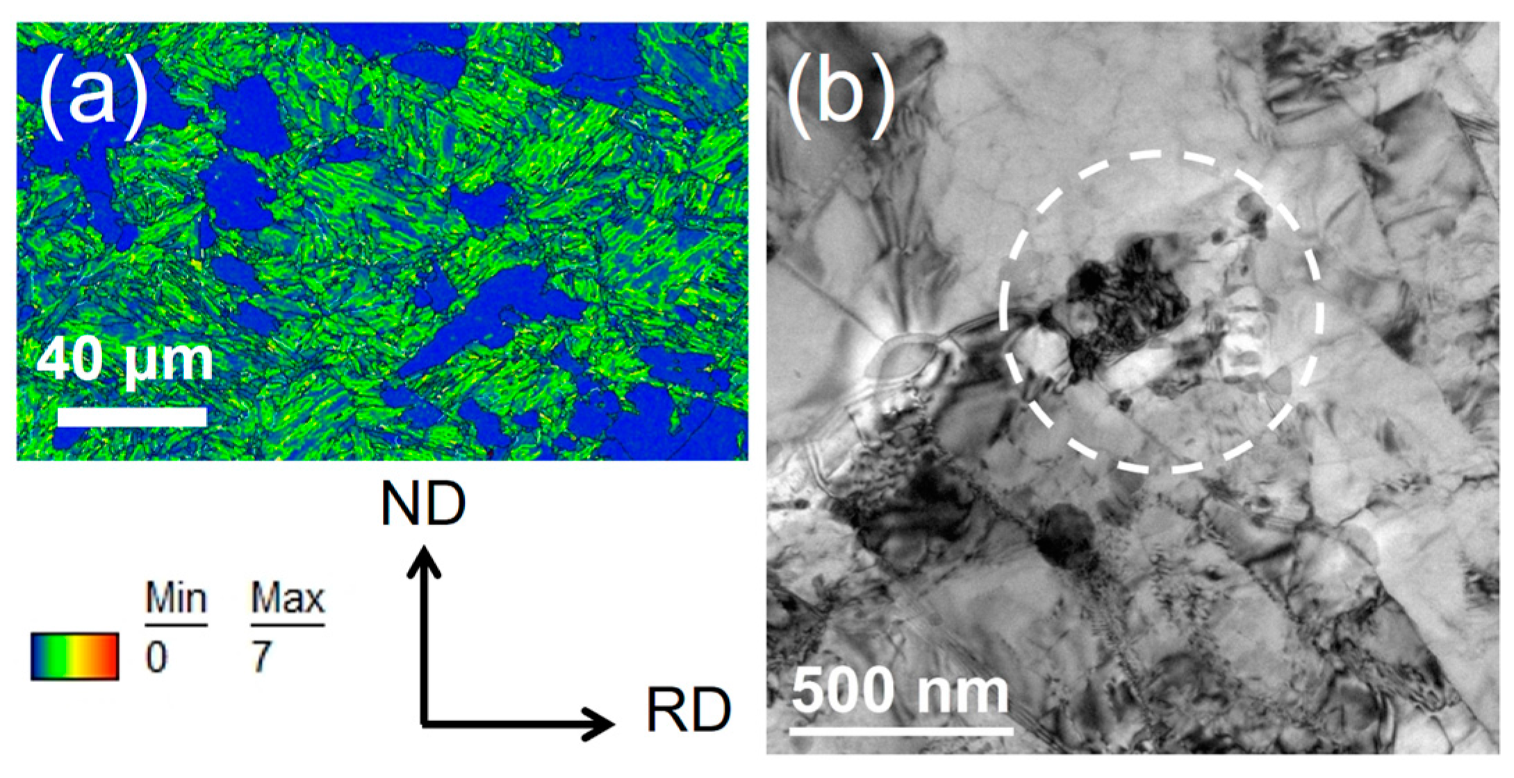
3.3. Analysis of Kernel Average Misorientation (KAM)

Morphology of lath martensite in low-carbon steels has a hierarchy leveled from laths, blocks, and up to packets [11]. It has been clearly shown that variants within each sub-block always have a low-angle boundary. The strict misorientation between two variants within a sub-block is 10.53°, but the orientation distribution is scattered [12]. Besides, misorientation gradients also arise because of the plastic stains induced in austenite due to the transformation strain of martensite growth [13]. Under this circumstance, the gradual change in misorientation can be featured by the substructure of dislocations. During tempering, recovery or growth of the plate can eliminate the misoriantation, leading to coalesced martensite. It has been suggested that coalescence of martensite or bainite can have detrimental effects on the toughness of steel [14,15].
Based on EBSD results, Kernel average misorientation (KAM) is a method calculating the averaged misorientations between the center point and all surrounding points in the Kernel [16]. Hence, KAM analysis provides the local misorientation value of the center point. Coalesced martensite can be identified by applying KAM analysis because it has lower averaged values of local misorientation. In the current work, a scanning step size of 400 nm was used, and the nearest neighboring was set as the 1st order. Figure 6a–d show the KAM analyses for the tempered S690Q steel. Misorientation between martensite laths occurred even within the same martensite block. Coalescence reduces the misorientation between laths. In this analysis, the blue areas are regions of low misorientation, indicating regions corresponding to coalesced martensite. It was found that raising the tempering temperature enhanced the level of coalescence. If coalescence of martensite is the main cause of embrittlement, toughness should have decreased with increasing tempering temperature. However, absorption energy revealed an inverse trend, and the embrittlement occurred only when S690Q steel was tempered at 720 °C and quenched. Hence, it is proposed that there are other factors causing the 720 °C tempered martensite embrittlement. After tempering at 780 °C, the coalesced martensite, or ferrite, was mixed with large amounts of new martensite.
Figure 6e–h presents the KAM analyses for the quenched and tempered NiCu steel. It was found that the level of coalescence of martensite was not high in this steel. When the steel was tempered at 720 °C, very weak effects of coalescence could be observed between martensite laths, as shown in Figure 6g. For detailed observations between the martensite laths, orientation mapping was conducted at higher resolution.

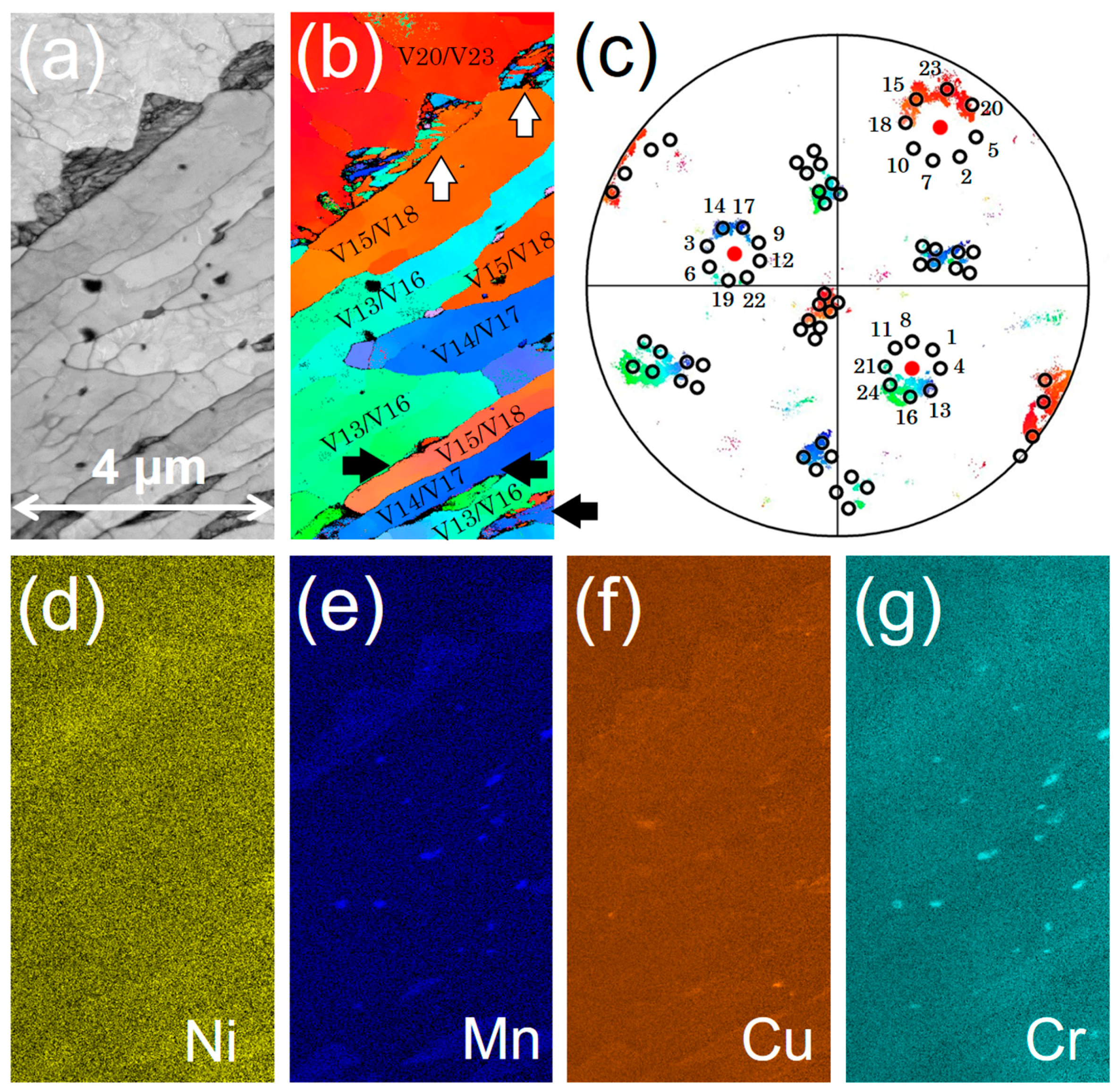
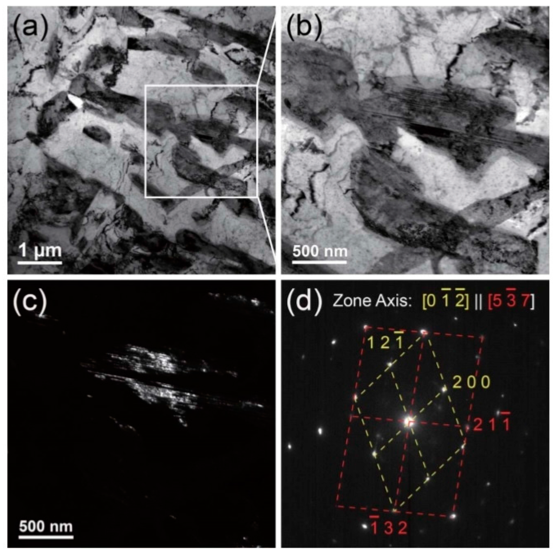
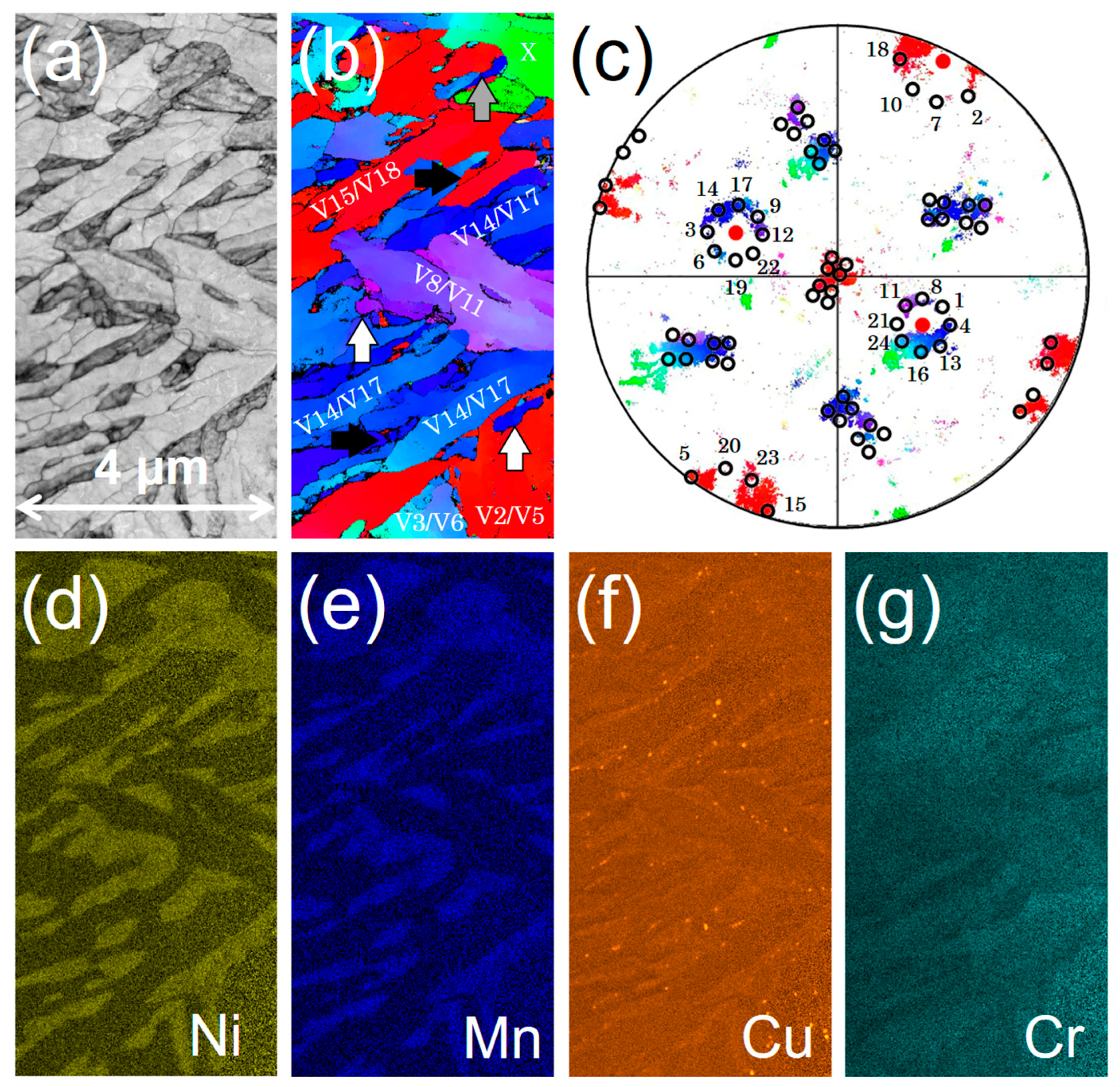
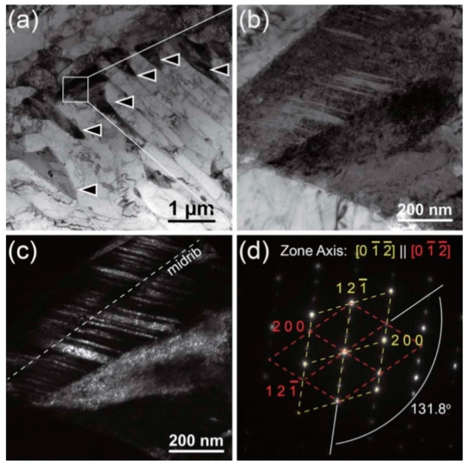
3.4. Investigations by Transmission Kikuchi Diffraction (TKD)

TKD can provide orientation mapping at nanoscale, and it has been applied in many studies of steels and alloys [17,18]. A scanning step size of 10 nm was used in this work. Figure 7 and Figure 8 show the TKD analyses of M/A phases in the S690Q and NiCu steels after 720 °C tempering. In the S690Q steel, the M/A phases appeared as islands with lower band contrast (darker), as shown in Figure 7a, and they were lenticular martensite, as shown in Figure 7b. Figure 7c shows experimental and simulated {1 0 0} pole figures of martensite corresponding to the colors in Figure 7b. The simulated {1 0 0} pole figure of martensite was obtained based on Miyamoto et al.’s method [19]. It should be noted that only the ideal Kurdjumov-Sachs (KS) orientation relationship (OR) [20] was used in the analyses. There are twenty-four variants of KS OR as shown in Table 2. Based on the crystallography analysis, V13/V16, V14/V17, and V15/V18 sub-blocks belong to the same packet because they have the same {1 1 1}γ plane. The V20/V23 sub-block belongs to another packet. Hence, the M/A phases formed along the boundary of the packet as indicated by white arrows in Figure 7b. Besides, the martensite variants in M/A phase hold a twinning relationship (V15 and V16; V15 and V13), and they look like interlocked saws. Martensite in M/A phase is suggested to be lenticular martensite with twinned martensitic variants. Only some tiny M/A phases formed along the boundaries of sub-blocks as pointed out by black arrows in Figure 7b. The distribution of these phases is consistent with the observation in Figure 2c. Moreover, the substitutional solutes, such as Ni, Mn, and Cu, were partitioned mainly into cementite particles and partially into reverted austenite, as shown in Figure 7d–g. Also, the partitioning of carbon explains the stability of austenite at 720 °C. Austenite with higher carbon content transformed into lenticular martensite during quenching.
Figure 8 shows that, after tempering at 720 °C, M/A phases extensively formed along martensite laths in the NiCu steel. Figure 8c shows experimental and simulated {1 0 0} pole figures of martensite corresponding to the colors in Figure 8b. The variant X, which is green in Figure 8b, does belong to the same austenite. Moreover, there are three packets in the primary austenite. V14/V17, and V15/V18 sub-blocks belong to one packet, V2/V5 and V3/V6 sub-blocks belong to one packet, and V8/V11 sub-block belongs to the other. In this case, the M/A phases formed along a prior austenite boundary (pointed out by gray arrow), packet boundaries (pointed out by white arrow), and sub-block or interlath boundaries (partially pointed out by dark arrow). Besides, the martensite variants in M/A phase hold a twinning relationship (V17 and V18), but they have no saw-like feature. Also, the new martensite in M/A phase was similar to lath martensite, but its morphology was not typical due to constraint by the size of the austenite grains. The extensive formation of interlath or interblock martensite helped to suppress the coalescence of martensite. In addition, during tempering, the solutes of Ni, Mn, Cu, and C were partitioned into reverted austenite along lath boundaries, and solutes of Cr were partitioned into prior martensite in the NiCu steel. As shown in Figure 8e, some precipitates of copper were observed. TKD mapping coupled with chemical mapping showed both microstructural and chemical information of the M/A phases.
The morphology of the martensite was further confirmed by TEM. Figure 9 shows lenticular martensite in the S690Q steel after tempering at 720 °C. The lenticular martensite can be recognized by its midrib and twinned orientation relationship [21]. Figure 10 shows lath martensite in the NiCu steel after tempering at 720 °C. Analysis of the axis-angle pairs in Figure 10d revealed that the laths or blocks had a twinned relationship. This relationship occurs when an austenite grain is fine; a single martensite packet with twinned blocks/laths replaces the whole austenite [11]. This structure is sometimes described as twinned lath martensite [17]. Moreover, in all our TEM investigations, it was very difficult to find lenticular martensite in the NiCu steel. It is known here that orientation mapping from TKD is able to provide information to distinguish lenticular martensite from lath martensite in M/A phase. With further crystallography analysis, locations for reverse austenite can also be identified. Coupled with EDS mapping, structural and chemical characterizations can be done in one scanned region at one time.

4. Discussion

This work found that embrittlement induced by high-temperature tempering was obvious in S690Q and absent in the newly-designed NiCu steel. This difference is explained by their microstructural differences, which were determined by their alloy compositions. After tempering at 720 °C, the microstructural differences can be summarized as follows:
  • The level of martensite coalescence is higher in S690Q steel;
  • Lenticular martensite forms as M/A phases in S690Q steel, whereas lath martensite forms as M/A phases in NiCu steel;
  • M/A phases form primarily along prior austenite grain boundaries or packet boundaries in S690Q steel, whereas M/A phases primarily form along lath boundaries in NiCu steel;
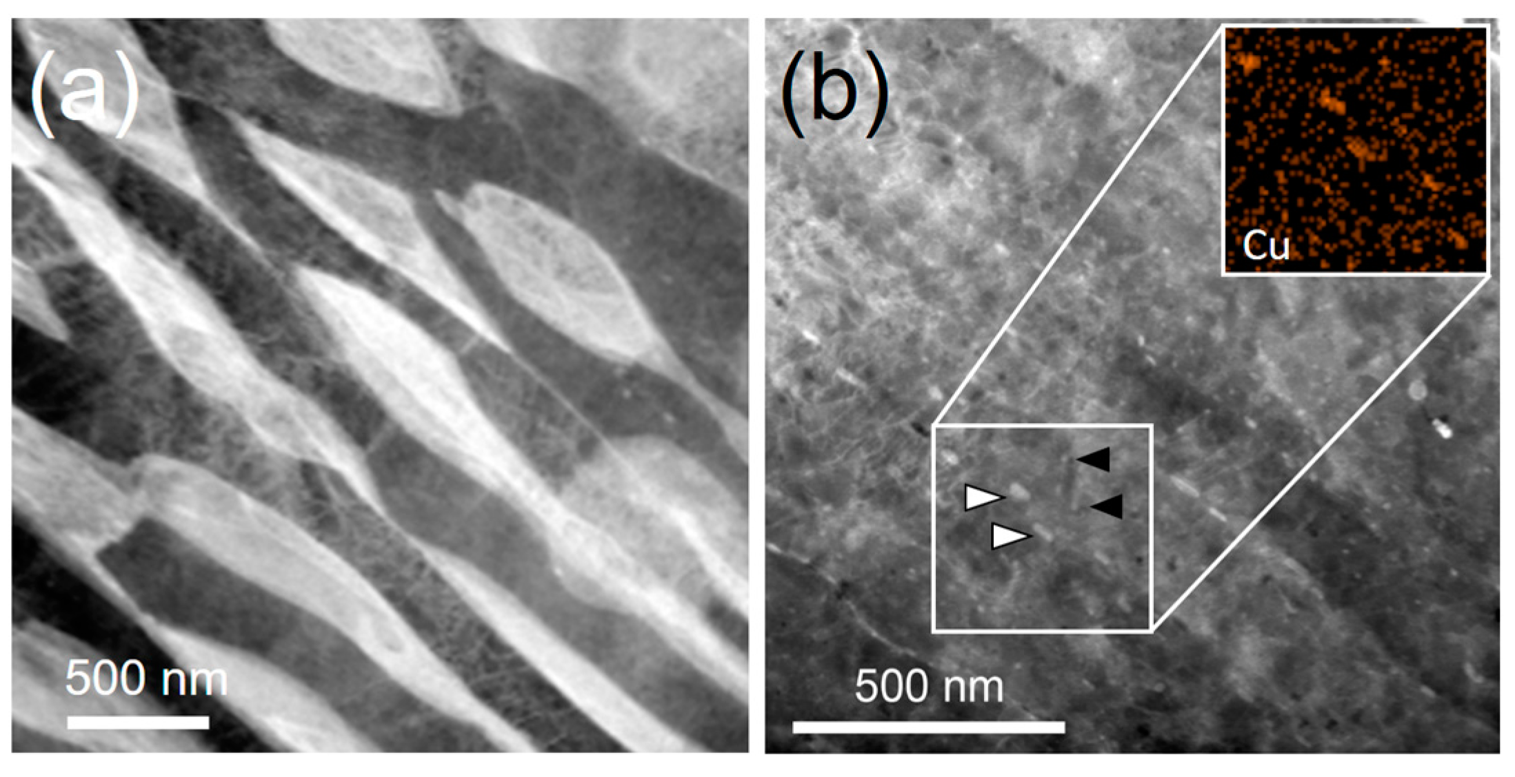
  • Copper particles form in NiCu steel.
The effect of martensite coalescence on this embrittlement is not significant, as discussed in Section 3.3. Although copper particles were discovered in the NiCu steel after 720 °C tempering, as shown in Figure 8f, their size is about 50–200 nm. Only a few nanometer-sized copper particles were observed, as shown in Figure 11a. When the NiCu steel tempered at 660 °C, extensive precipitation of copper particles was observed, as shown in Figure 11b. The precipitation of copper at 660 °C involves tiny intralath particles (pointed out by black arrows) with sizes of 5–20 nm and coarser interlath particles with sizes of 20–50 nm (pointed out by white arrows). After 720 °C tempering, the particle size is much coarser, and the density is extremely low. Hence, when comparing the toughness of S690Q and NiCu steels after 720 °C tempering, the difference caused by copper precipitation is suggested to be truly minor. Exactly speaking, microstructure that is free of copper precipitation in S690Q steel is not the cause of this embrittlement. Based on the above discussions, it is suggested that the high-temperature tempered martensite embrittlement in S690Q steel results primarily from the formation of lenticular martensite. To support this point, secondary tempering at 550 °C for 1 h was conducted on S690Q steel previously tempered at 720 °C. In this case, the impact toughness at −40 °C exceeded 200 J. The KAM analysis in Figure 12a shows that the level of coalescence after secondary tempering was even higher than that after only 720 °C tempering. Here, coalesced martensite was not the main factor of embrittlement. Figure 12b clearly shows that the lenticular martensite decomposed into cementite/ferrite aggregates. Hence, the formation of lenticular martensite leads to the loss in toughness in S690Q steel.
Figure 13 shows the equilibrium phase fractions as a function of temperature for the two offshore steels. The results were calculated by Thermo-Calc with the TCFE8 database. The design principle of NiCu steel is to reduce the carbon content and to increase the copper content in order to obtain precipitation hardening from copper after tempering. Its higher resistance to high-temperature tempered martensite embrittlement can be understood by its phase constituents during tempering. As shown in Figure 13b, the equilibrium fraction of austenite is about 0.43 at 720 °C in the NiCu steel, and the carbon content of austenite is only about 0.09 wt %. In S690Q steel (Figure 13a), however, the equilibrium fraction of austenite is about 0.23, and the carbon content of austenite is about 0.41 wt %. Austenite with carbon content of 0.41 wt % will transform into lenticular martensite [4,11]. Moreover, the high volume fraction of new martensite, which directly forms along prior interlath boundaries, suppresses the coalescence of martensite. This microstructure also increases the toughness. Hence, in addition to the reported benefits of copper-containing high-strength low alloy steels [22,23], this alloy design shows better resistance to the high-temperature tempered martensite embrittlement that occurs in S690Q steel during welding.

5. Conclusions

In this work, EBSD-KAM analysis and TKD mapping were used to investigate high-temperature tempered martensite embrittlement in steels for offshore structures. It was found that the formation of lenticular martensite during a thermal cycle of high-temperature tempering and quenching is more detrimental to the toughness of S690Q offshore steel than is the coalescence of martensite. In the newly designed nickel-copper-containing low-carbon steel, low-carbon lath martensite forms between prior martensite laths after 720 °C tempering, and this steel shows better resistance to high-temperature tempered martensite embrittlement.

Acknowledgments

This work was supported by the following projects: (1) MOST 105-2622-8-006-001 and (2) MOST 104-2218-E-002-022-MY3. The authors thank Jer-Ren Yang at the Department of Materials Science and Engineering, National Taiwan University, for his generous support in the experimental facilities of TEM sample preparation. Moreover, we specially thank Yuan-Tzu Lee for her technical support in FEG-SEM (JSM 7800F PRIME) at the Instrumentation Center, National Taiwan University, under the Ministry of Science and Technology, R.O.C.

Author Contributions

Hung-Wei Yen and Hsin-Chih Lin conceived the idea of this work and designed the materials. Delphic Chen and Ching-Yuan Huang prepared the steels and conducted the thermo-mechanical controlled processes at China Steel Corporation. Meng-Hsuan Chiang and Yu-Chen Lin conducted the heat treatments, measurements of impact toughness, and SEM characterizations. All of the authors discussed the results and reviewed the manuscript.

Conflicts of Interest

The chemical compositions of the steels were listed as ranges to prevent disclosure of the intellectual property of the China Steel Corporation. This practice does not change the main finding of this manuscript. The authors declare no conflict of interest.

References

  1. Standard, N. Material Data Sheets for Structural Steel; Norwegian Technology Center: Oslo, Norway, 2000; Volume M-120. [Google Scholar]
  2. MacKenzie, S. Overview of the mechanisms of failure in heat treated steel components. In Failure Analysis of Heat Treated Steel Components; Totten, G.E., Canale, L.D.C.F., Mesquita, R.A., Eds.; ASM International: Materials Park, OH, USA, 2008; p. 640. [Google Scholar]
  3. Sinha, A.K. Physical Metallurgy Handbook; McGraw-Hill: New York, NY, USA, 2003. [Google Scholar]
  4. Honeycombe, R.K.W.; Bhadeshia, H.K.D.H. Steels: Microstructure and Properties, 3rd ed.; Elsevier Ltd., International: Butterworth-Heinemann, Oxford, UK, 2006. [Google Scholar]
  5. Briant, C.L.; Banerji, S.K. Tempered martensite embrittlement in phosphorus doped steels. Metall. Trans. A 1979, 10, 1729–1737. [Google Scholar] [CrossRef]
  6. Thomas, G. Retained austenite and tempered martensite embrittlement. Metall. Trans. A 1978, 9, 439–450. [Google Scholar] [CrossRef]
  7. Sarikaya, M.; Jhingan, A.K.; Thomas, G. Retained austenite and tempered martensite embrittlement in medium carbon steels. Metall. Trans. A 1983, 14, 1121–1133. [Google Scholar] [CrossRef]
  8. Materkowski, J.P.; Krauss, G. Tempered martensite embrittlement in sae 4340 steel. Metall. Trans. A 1979, 10, 1643–1651. [Google Scholar] [CrossRef]
  9. Horn, R.M.; Ritchie, R.O. Mechanisms of tempered martensite embrittlement in low alloy steels. Metall. Trans. A 1978, 9, 1039–1053. [Google Scholar] [CrossRef]
  10. Bhadeshia, H.; Edmonds, D. Tempered martensite embrittlement: Role of retained austenite and cemenite. Met. Sci. 1979, 13, 325–334. [Google Scholar]
  11. Krauss, G. Steels: Processing, Structure, and Performance; ASM International: Materials Park, OH, USA, 2005. [Google Scholar]
  12. Kitahara, H.; Ueji, R.; Tsuji, N.; Minamino, Y. Crystallographic features of lath martensite in low-carbon steel. Acta Mater. 2006, 54, 1279–1288. [Google Scholar] [CrossRef]
  13. Pak, J.H.; Bhadeshia, H.K.D.H.; Karlsson, L. Mechanism of misorientation development within coalesced martensite. Mater. Sci. Technol. 2012, 28, 918–923. [Google Scholar] [CrossRef]
  14. Pous-Romero, H.; Bhadeshia, H. Coalesced martensite in pressure vessel steels. J. Press. Vessel Technol. 2014, 136, 031402–031406. [Google Scholar] [CrossRef]
  15. Bhadeshia, H.K.D.H.; Keehan, E.; Karlsson, L.; Andrén, H.O. Coalesced bainite. Trans. Indian Inst. Met. 2006, 59, 6. [Google Scholar]
  16. Wright, S.I.; Nowell, M.M.; Field, D.P. A review of strain analysis using electron backscatter diffraction. Microsc. Microanal. 2011, 17, 316–329. [Google Scholar] [CrossRef] [PubMed]
  17. Yen, H.-W.; Ooi, S.W.; Eizadjou, M.; Breen, A.; Huang, C.-Y.; Bhadeshia, H.K.D.H.B.; Ringer, S.P. Role of stress-assisted martensite in the design of strong ultrafine-grained duplex steels. Acta Mater. 2015, 82, 100–114. [Google Scholar] [CrossRef]
  18. Trimby, P.W.; Cao, Y.; Chen, Z.; Han, S.; Hemker, K.J.; Lian, J.; Liao, X.; Rottmann, P.; Samudrala, S.; Sun, J.; et al. Characterizing deformed ultrafine-grained and nanocrystalline materials using transmission kikuchi diffraction in a scanning electron microscope. Acta Mater. 2014, 62, 69–80. [Google Scholar] [CrossRef]
  19. Miyamoto, G.; Takayama, N.; Furuhara, T. Accurate measurement of the orientation relationship of lath martensite and bainite by electron backscatter diffraction analysis. Scr. Mater. 2009, 60, 1113–1116. [Google Scholar] [CrossRef]
  20. Kurdjumov, G.V.; Sachs, G. ber den mechanismus der stahlhӓrtung. Z. Phys. 1930, 64, 325–343. [Google Scholar] [CrossRef]
  21. Lee, H.-Y.; Yen, H.-W.; Chang, H.-T.; Yang, J.-R. Substructures of martensite in Fe-1C-17Cr stainless steel. Scr. Mater. 2010, 62, 670–673. [Google Scholar] [CrossRef]
  22. Mujahid, M.; Lis, A.K.; Garcia, C.I.; DeArdo, A.J. Hsla-100 steels: Influence of aging heat treatment on microstructure and properties. J. Mater. Eng. Perform. 1998, 7, 247–257. [Google Scholar] [CrossRef]
  23. Ray, P.K.; Ganguly, R.I.; Kumar Panda, A. Influence of heat treatment parameters on structure and mechanical properties of an hsla-100 steel. Steel Res. 2002, 73, 347–355. [Google Scholar] [CrossRef]
Figure 1. The optical metallography images showing the as-quenched microstructure in (a) S690Q steel and (b) NiCu steel.
Metals 07 00253 g001
Figure 2. Optical metallography images showing the as-quenched microstructure in S690Q steel after tempering at (a) 600 °C; (b) 660 °C; (c) 720 °C; and (d) 780 °C for 1 h.
Metals 07 00253 g002
Figure 3. Optical metallography images showing the as-quenched microstructure of NiCu steel after tempering at (a) 600 °C; (b) 660 °C; (c) 720 °C; and (d) 780 °C for 1 h.
Metals 07 00253 g003
Figure 4. (a) Vickers hardness and (b) impact toughness (−40 °C) of two steels after quenching and tempering.
Metals 07 00253 g004
Figure 5. SEM-secondary electron images showing the fracture surfaces in the propagation regions after Charpy tests in 720 °C-tempered (a) S690Q steel and (b) NiCu steel.
Metals 07 00253 g005
Figure 6. Kernel average misorientation (KAM) analyses of S690Q steel after tempering at (a) 600 °C; (b) 660 °C; (c) 720 °C; and (d) 780 °C for 1 h; and NiCu steel after tempering at (e) 600 °C; (f) 660 °C; (g) 720 °C; and (h) 780 °C for 1 h. RD is the rolling direction, and ND is the normal direction of the steel plate.
Metals 07 00253 g006
Figure 7. Transmission Kikuchi diffraction (TKD) mapping showing (a) band contrast; (b) inverse pole figure—Z; (c) experimental and simulated pole figures; (d) Ni distribution; (e) Mn distribution; (f) Cu distribution; and (g) Cr distribution in S690Q steel after tempering at 720 °C.
Metals 07 00253 g007
Figure 8. TKD mapping showing (a) band contrast; (b) inverse pole figure—Z; (c) experimental and simulated pole figures; (d) Ni distribution; (e) Mn distribution; (f) Cu distribution; and (g) Cr distribution in NiCu steel after tempering at 720 °C.
Metals 07 00253 g008
Figure 9. TEM micrographs showing the fine structure of M/A phases in S690Q steel after tempering at 720 °C. (a) Bright-field image at low magnification; (b) bright-field image; (c) dark-field image; and (d) electron diffraction pattern.
Metals 07 00253 g009
Figure 10. TEM micrographs showing the fine structure of M/A phases in NiCu steel after tempering at 720 °C. (a) Bright-field image at low magnification; (b) bright-field image; (c) dark-field image; and (d) electron diffraction pattern.
Metals 07 00253 g010
Figure 11. High-angle annular dark-field (HAADF) image showing microstructure in (a) S690Q steel and (b) NiCu steel after a 720 °C tempering for 1 h.
Metals 07 00253 g011
Figure 12. (a) KAM analysis and (b) TEM image showing microstructure of 690Q steel after a 720 °C tempering for 1 h, followed by secondary tempering at 550 °C for 1 h. RD is the rolling direction, and ND is the normal direction of steel plate.
Metals 07 00253 g012
Figure 13. Equilibrium phase fractions as a function of temperature for (a) S690Q steel and (b) NiCu steel.
Metals 07 00253 g013
Table 1. The chemical compositions of studied offshore steels (in wt %).
FeCSiMnCrNiMoCuAlTi + NbN
S690Q 1Bal.0.08–0.160.20–0.400.90–1.00<0.650.80–1.00<0.500.10–0.40<0.08<0.04<0.009
FeCSiMnCrNiMoCuAlTi + Nb + VN
NiCu 2Bal.0.04–0.080.20–0.400.90–1.00<0.652.5–3.5<0.501.0–2.0<0.08<0.06<0.009
1 S ~0.0028 wt % and P ~0.01 wt %; 2 S ~0.0014 wt % and P ~0.01 wt %.
Table 2. The twenty-four crystallographic variants for Kurdjumov-Sachs (KS) orientation relationship evolved from a single austenite grain.
Variant NumberPlane ParallelDirection Parallel
V1 ( 1 1 1 ) γ ( 0 1 1 ) α [ 1 ¯ 0 1 ] γ [ 1 ¯ 1 ¯ 1 ] α
V2 ( 1 1 1 ) γ ( 0 1 1 ) α [ 1 ¯ 0 1 ] γ [ 1 ¯ 1 1 ¯ ] α
V3 ( 1 1 1 ) γ ( 0 1 1 ) α [ 0 1 1 ¯ ] γ [ 1 ¯ 1 ¯ 1 ] α
V4 ( 1 1 1 ) γ ( 0 1 1 ) α [ 0 1 1 ¯ ] γ [ 1 ¯ 1 1 ¯ ] α
V5 ( 1 1 1 ) γ ( 0 1 1 ) α [ 1 1 ¯ 0 ] γ [ 1 ¯ 1 ¯ 1 ] α
V6 ( 1 1 1 ) γ ( 0 1 1 ) α [ 1 1 ¯ 0 ] γ [ 1 ¯ 1 1 ¯ ] α
V7 ( 1 1 ¯ 1 ) γ ( 0 1 1 ) α [ 1 0 1 ¯ ] γ [ 1 ¯ 1 ¯ 1 ] α
V8 ( 1 1 ¯ 1 ) γ ( 0 1 1 ) α [ 1 0 1 ¯ ] γ [ 1 ¯ 1 1 ¯ ] α
V9 ( 1 1 ¯ 1 ) γ ( 0 1 1 ) α [ 1 ¯ 1 ¯ 0 ] γ [ 1 ¯ 1 ¯ 1 ] α
V10 ( 1 1 ¯ 1 ) γ ( 0 1 1 ) α [ 1 ¯ 1 ¯ 0 ] γ [ 1 ¯ 1 1 ¯ ] α
V11 ( 1 1 ¯ 1 ) γ ( 0 1 1 ) α [ 0 1 1 ] γ [ 1 ¯ 1 ¯ 1 ] α
V12 ( 1 1 ¯ 1 ) γ ( 0 1 1 ) α [ 0 1 1 ] γ [ 1 ¯ 1 1 ¯ ] α
V13 ( 1 ¯ 1 1 ) γ ( 0 1 1 ) α [ 0 1 ¯ 1 ] γ [ 1 ¯ 1 ¯ 1 ] α
V14 ( 1 ¯ 1 1 ) γ ( 0 1 1 ) α [ 0 1 ¯ 1 ] γ [ 1 ¯ 1 1 ¯ ] α
V15 ( 1 ¯ 1 1 ) γ ( 0 1 1 ) α [ 1 ¯ 0 1 ¯ ] γ [ 1 ¯ 1 ¯ 1 ] α
V16 ( 1 ¯ 1 1 ) γ ( 0 1 1 ) α [ 1 ¯ 0 1 ¯ ] γ [ 1 ¯ 1 1 ¯ ] α
V17 ( 1 ¯ 1 1 ) γ ( 0 1 1 ) α [ 1 1 0 ] γ [ 1 ¯ 1 ¯ 1 ] α
V18 ( 1 ¯ 1 1 ) γ ( 0 1 1 ) α [ 1 1 0 ] γ [ 1 ¯ 1 1 ¯ ] α
V19 ( 1 1 1 ¯ ) γ ( 0 1 1 ) α [ 1 ¯ 1 0 ] γ [ 1 ¯ 1 ¯ 1 ] α
V20 ( 1 1 1 ¯ ) γ ( 0 1 1 ) α [ 1 ¯ 1 0 ] γ [ 1 ¯ 1 1 ¯ ] α
V21 ( 1 1 1 ¯ ) γ ( 0 1 1 ) α [ 0 1 ¯ 1 ¯ ] γ [ 1 ¯ 1 ¯ 1 ] α
V22 ( 1 1 1 ¯ ) γ ( 0 1 1 ) α [ 0 1 ¯ 1 ¯ ] γ [ 1 ¯ 1 1 ¯ ] α
V23 ( 1 1 1 ¯ ) γ ( 0 1 1 ) α [ 1 0 1 ] γ [ 1 ¯ 1 ¯ 1 ] α
V24 ( 1 1 1 ¯ ) γ ( 0 1 1 ) α [ 1 0 1 ] γ [ 1 ¯ 1 1 ¯ ] α

