Article

Effect of Cooling Rate on Microstructure and Grain Refining Behavior of In Situ CeB6/Al Composite Inoculant in Aluminum

Key Laboratory for New Type of Functional Materials in Hebei Province, School of Materials Science and Engineering, Hebei University of Technology, Tianjin 300130, China
*
Author to whom correspondence should be addressed.
Metals 2017, 7(6), 204; https://doi.org/10.3390/met7060204
Submission received: 28 April 2017 / Revised: 28 May 2017 / Accepted: 31 May 2017 / Published: 2 June 2017

Abstract

:
Melt spinning was performed to process an in situ CeB6/Al inoculant at different rotating speeds to investigate the influence of cooling rate on the grain refining behavior of inoculants. It has been found that a high cooling rate caused two obvious changes in the inoculant: the supersaturated solid solution of Ce in the α-Al matrix and the miniaturization of CeB6 particles. At high cooling rates of ~108 K/s, the Ce content is largely beyond the theoretical solid solubility of Ce in Al, and the size of the CeB6 particles in ribbons is reduced to ~100 nm. The grain refining effect of melt-spun CeB6/Al composite inoculant shows significant dependence on holding time of which the best value should be no more than 2 min. The excellent grain refinement of the inoculant can be attributed to the combined effect of the nano-sized refiner particles and the large undercooling caused by the sudden melting of supersaturated Al–Ce solution.

Graphical Abstract

1. Introduction

Grain refinement in aluminum alloys has obtained much attention in the casting industry, due to the significant enhancement of mechanical performance with the addition of minute quantities of inoculant [1,2]. To improve the grain refining efficiency of inoculation, many methods and strategies have been proposed, including chemical modification [3], rapid solidification [4,5,6,7,8], and ultrasonic processing [9], etc. Meanwhile, many theoretical and experimental investigations have aimed at revealing the procedure when inoculants are added to melts [10,11,12,13]. However, the detailed behavior of the interaction of different grain refiners with aluminum melt during grain refining treatment has not yet been fully understood.
As typical rapid solidification technology, melt spinning has been paid much attention for microstructure refinement, chemical homogeneity and improvement of solid solubility [8,14,15]. In particular, it is possible to promote the formation of ultra-fine secondary phase particles when the cooling rate exceeds 104 K/s [16,17,18]. For example, Xu et al. [19] proposed that when the cooling rate of Al–20 wt. % Si is 1.11 × 10⁶ K/s, the size of primary silicon is drastically changed from 5 to 500 nm. Karaköse and Keskin [20] studied the effects of different cooling rates on the microstructure of Al–8Si–Sb ribbon and found 2.7 times improvements in hardness. Recently, Dong et al. [21] investigated the formation of Al–9Si–Cu ribbons with a thickness of 54 μm and found that very fine and homogeneous Si particles are disperse in Al matrix. Since melt-spinning has such significant effect on refining the high-melting point phase in aluminum alloys, it also raises attention on processing of inoculant [22,23,24].
Recently, we used an arc–melt–spinning technique to prepare an in situ CeB6/Al inoculant and showed that it is very effective for refining aluminum [25]. We also developed a low-temperature synthesis method to optimize this inoculant and found that the melt-spun inoculant contains sub-micron CeB6 clusters and low-melting-point Al–Ce phase [26]. To examine the refining effect of this inoculant under more casting conditions, we did the inoculation experiment under different holding time that is considered an important parameter to measure the performance of the inoculant [27,28]. We found that the cooling rate is also effective on holding time and we proposed a stationary model to explain the corresponding mechanism.

2. Materials and Methods

Commercial Al–20Ce (in wt. %) and Al–3B (in wt. %) alloys were used as starting materials to prepare the Al–B–Ce master alloy in a graphic crucible (Yihui casting factory, Guangzhou, China) by arc melting under an argon atmosphere. During melting, the temperature of the reaction melt was monitored by a double color infrared laser thermometer (Fluke factory, Shanghai, China). Then the master alloy was re-melted by induction melting and blew on a single copper roller (Chinese academy of science, three–ring long magnetic equipment factory, Jiangsu, China) with a diameter of 22 cm to prepare the CeB6/Al ribbons. The rotating speed of the copper roller was set as 2000 and 8000 rpm, respectively (denoted as C1 and C2). In contrast, the casting obtained using a copper mold [29] with a diameter of 10 cm was denoted as alloy C0.
The CeB6/Al ribbons with different rotating speeds were used as inoculants and added into aluminum melt at 720 °C with an adding ratio of 0.4% that has been confirmed as the best addition amount previously [25]. After different holding times (1, 2, 5, and 30 min), the treated melts were stirred for 10 s and then poured into a steel mold with a cavity of 20 mm in diameter and 120 mm in height. The specimens for metallographic examination were cut from the middle part of each as-cast rod and carefully grinded by sandpaper. After mechanical polishing, the specimens were etched with Poulton’s reagent (60% HCl + 30% HNO3 + 5% HF + 5% H2O) for macroscopic observation. Next, the specimens were re-polished and etched in a 0.5% vol. % HF solution for microscopic observation using optical microscope (OM, Olympus, Jiang dong ou yi testing instrument, Ningbo, China). The grain size of each sample was measured using the intercept method according to ASTM standard E112.
The specimens were characterized by Bruker D8 Discover X-ray diffraction (XRD, Bruker AXS, Karlsruhe, Germany) with Cu Ka radiation, S4800 scanning electron microscope (SEM, Hitachi, Tokyo, Japan) and Olympus optical microscope (OM). High-Resolution Transmission Electron Microscope (HRTEM) was performed on a JEOL 2000FX instrument (Shimadzu Corporation, Kyoto, Japan).

3. Results

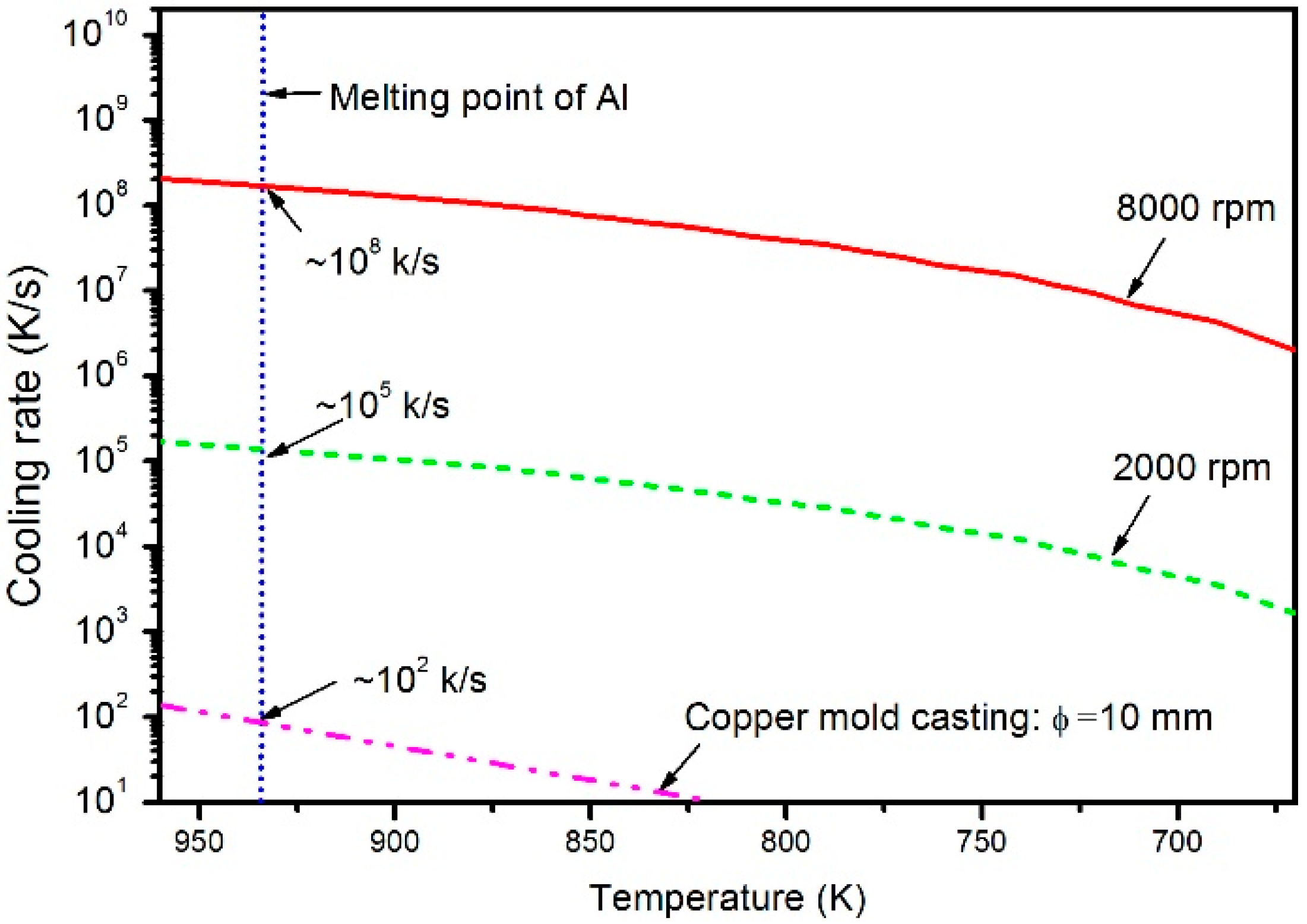
3.1. Confirmation of Cooling Rate

Figure 1 shows the curves plotted using the temperature versus cooling rate. The thickness of the CeB6/Al ribbons produced by different rotating speed of copper wheel C1 and C2 is about 136 and 14 μm, respectively. As is well known, the thickness of spinning ribbon relates to the cooling rate of the melt during the solidification. Therefore, the actual cooling rates of the CeB6/Al ribbons and solidification times can be calculated from their thicknesses. The cooling rate of a ribbon is governed by the Fourier’s equation of heat transfer [19], as follows:
T t = α T 2 x 2 α = k / c ρ
where T, t, α, c, and ρ are temperature (K), cooling time (s), thermal conductivity (W/(m·K)), specific heat capacity (J/(kg·K)), and density (kg/m3), respectively. According to the literature [18], the thermal storage coefficient b = k c ρ (W S /(m2·K)), the ribbon–wheel interface temperature Ti can be expressed as
T i   =   b 1 T 10 + b 2 T 20 b 1 + b 2
So, the temperature distribution of the melt spinning ribbon can be obtained as
T 1 = T i + ( T i T 10 ) e r f ( χ 2 α 1 t )
Taking the temperature T as a function of the cooling time t, the cooling rate at the thickness χ is given by
[ T 1 t ] χ = b 2 ( T 20 T 10 ) χ 2 ( b 1 + b 2 ) t π α 1 t e x p [ ( χ 2 α 1 t ) 2 ]
The solidification time of melt spinning ribbon can be obtained from
t s = { π χ ρ 1 [ L + c 1 ( T 10 T s ) ] 2 b 2 ( T i T 20 ) } 2
where L is the latent heat of aluminum. The values of the parameters we used are according to the reference [19], which are all listed in Table 1. Figure 1 shows the curves plotted using the temperature versus cooling rate based on Equation (3). By taking the melt point temperature of pure Al as the solidification temperature, the average cooling rates of different thicknesses ribbons are then the derivative values of the nodes, which are 8.4 × 10² K/s, 5.1 × 10⁵ K/s, and 1.6 × 10⁸ K/s, respectively. Obviously, the ribbons with thickness difference of about 1000 times show great difference of about three orders of magnitude in the corresponding cooling rates.

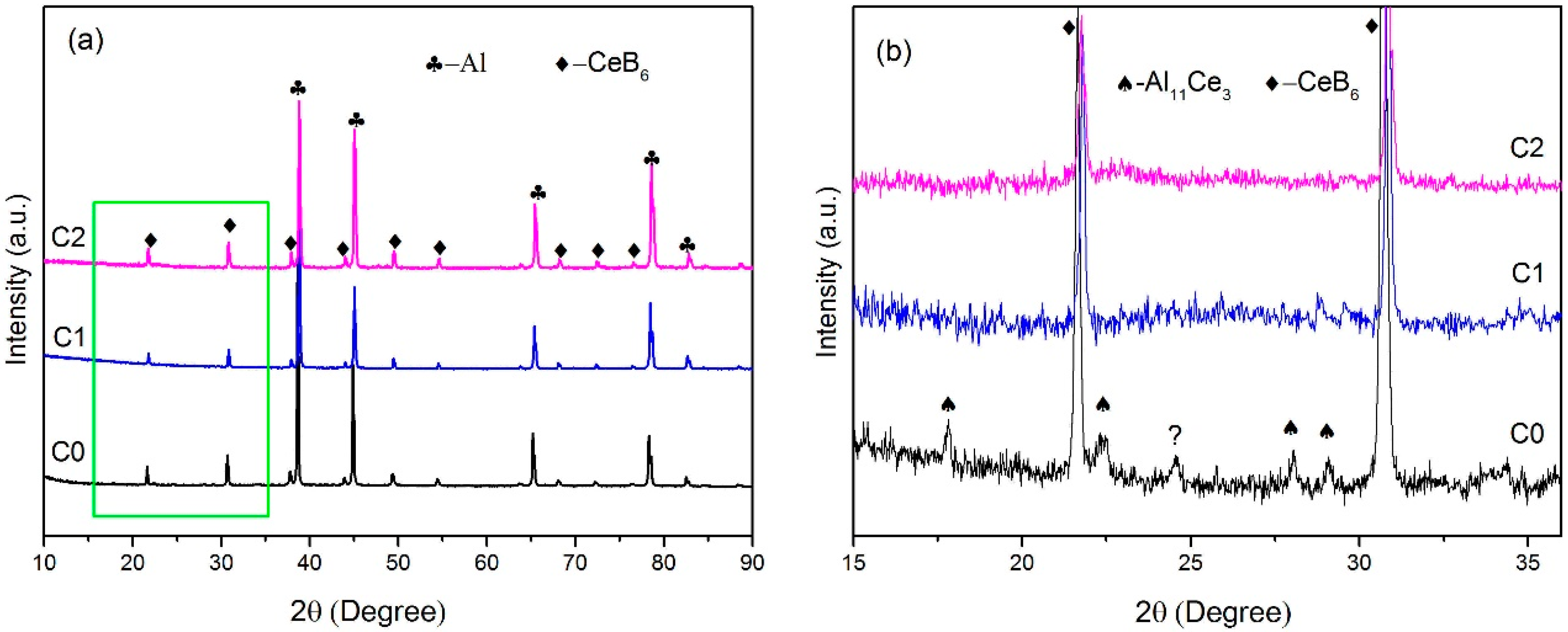
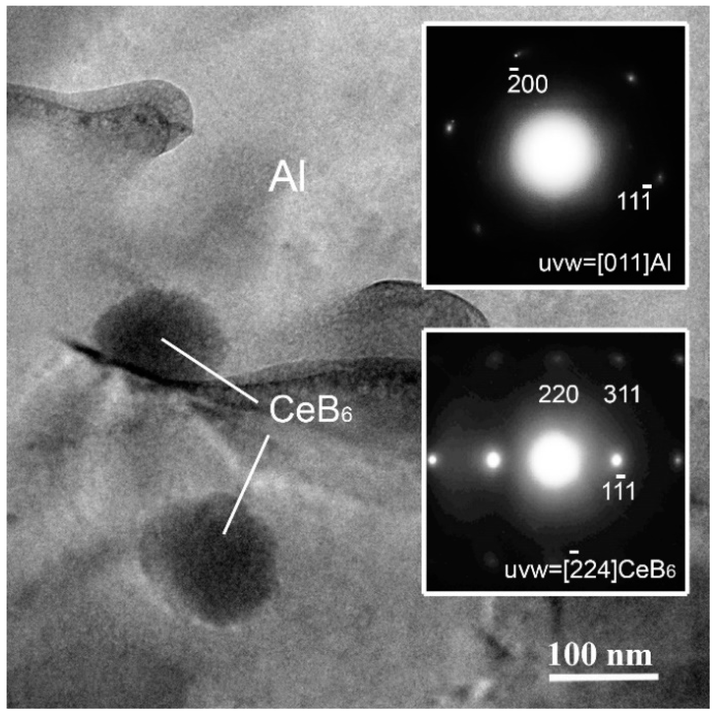
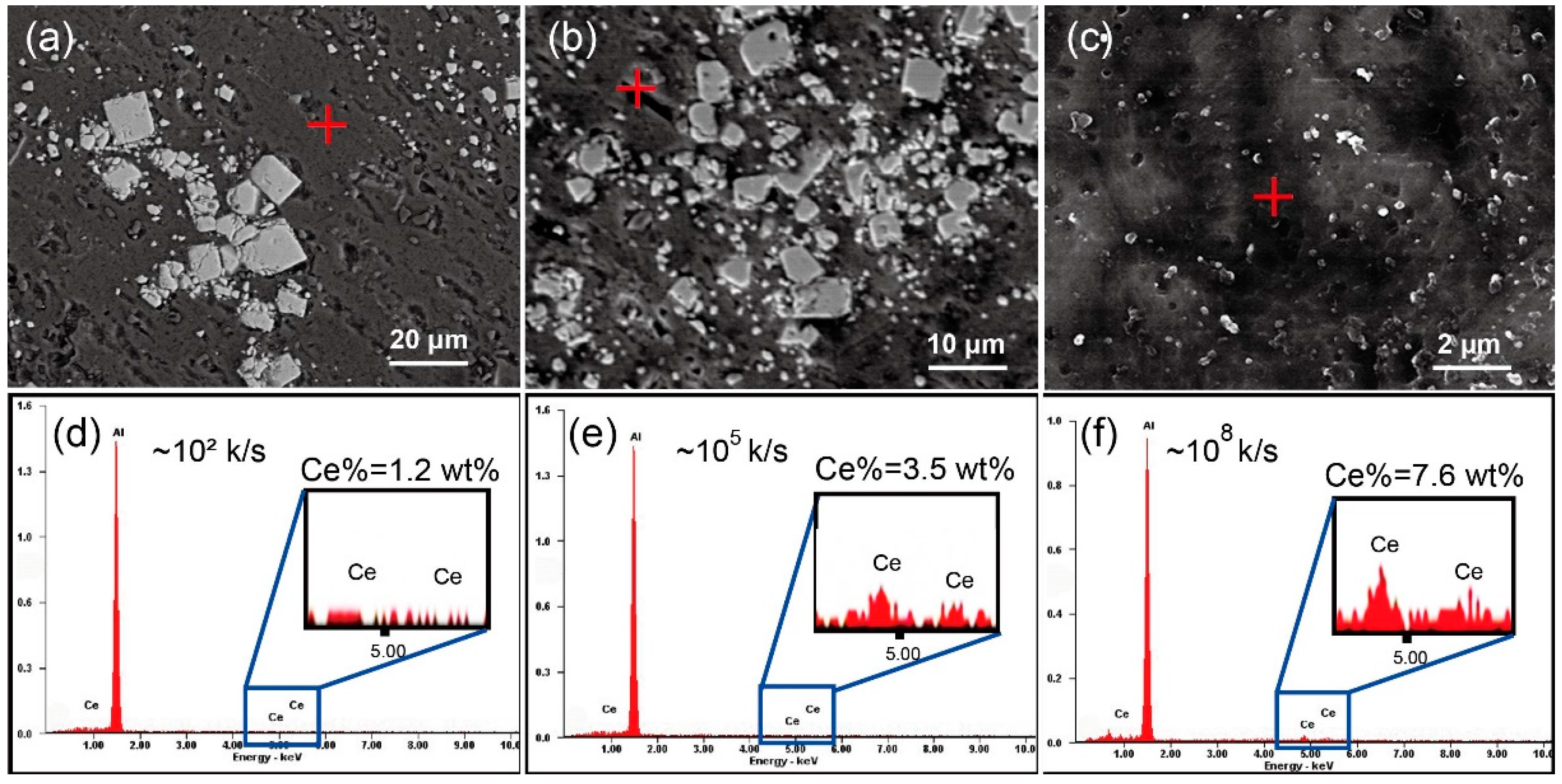
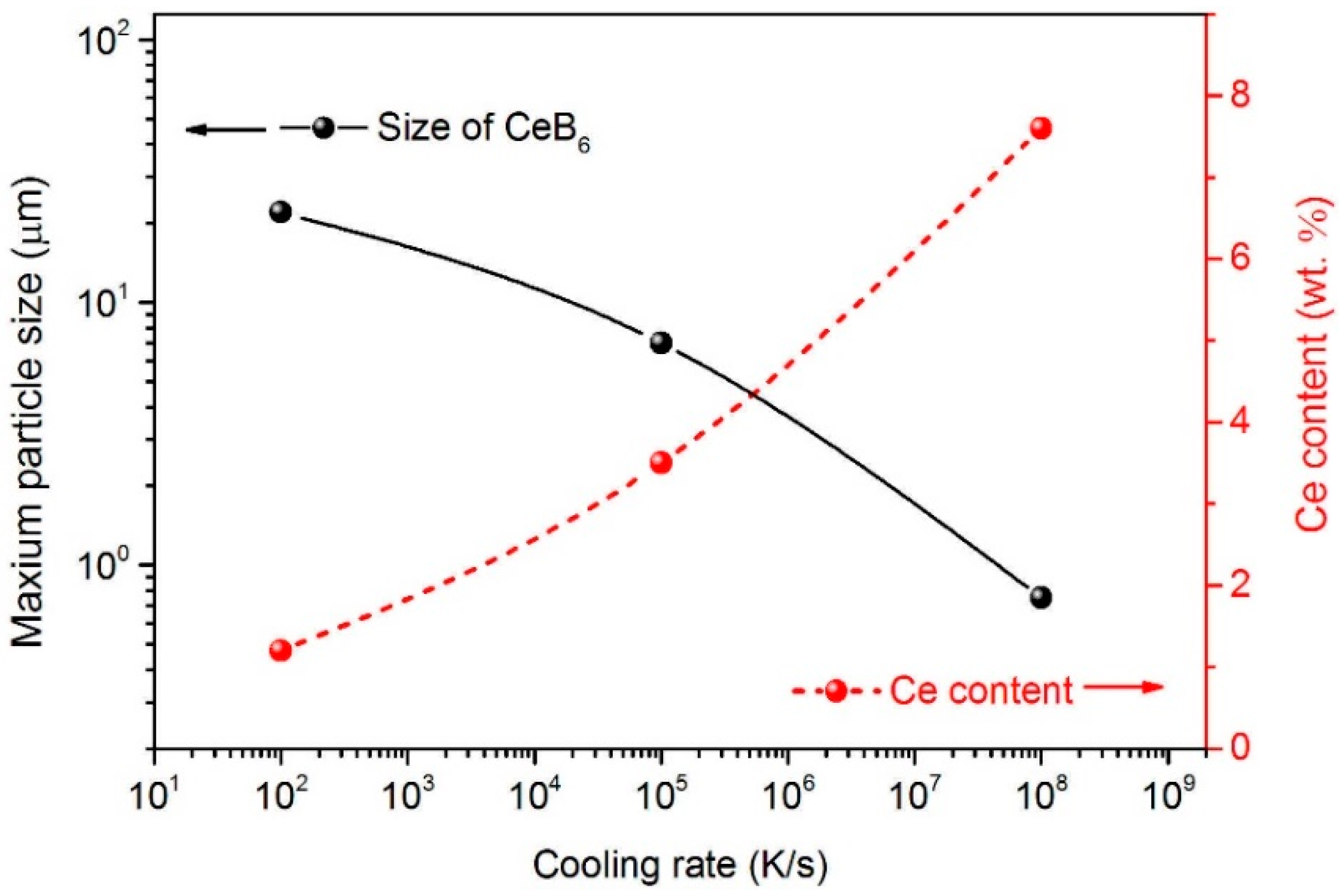
3.2. Effect of Cooling Rate on the Microstructure

The XRD patterns of the C0, C1, and C2 alloy are shown in Figure 2. All the XRD spectra are presented with obvious peaks of α-Al and CeB6 phase, indicating the successful synthesis of CeB6 phase. In theory, the successful synthesis of CeB6 might be attributed to the energy status of the active Ce atoms and B atoms due to the presence of liquid Al melt. Besides, the enlarged view of XRD spectrum of the ribbon samples produced by different rotating speed is shown as Figure 2b. It is noticed that some weak peaks of Al11Ce3 are also detected in C0 alloy. However, with the cooling rate increased, the peak of Al11Ce3 phase disappears.
Figure 3 shows the TEM images of the C3 ribbon. It is found that some particles with an average size of about 100 nm are dispersing in the matrix. To further confirm the particles and matrix shown in Figure 3, the electron diffraction data are shown as the inset in Figure 3. It is indicated that the particles are CeB6 phase and the matrix is Al, which is in accordance with the XRD results shown in Figure 2.
Figure 4 shows the SEM images of the C0 and CeB6/Al ribbons produced by different cooling rates. As shown in Figure 4a, many white particles with different sizes, which are aggregated in the matrix. It should be noted that in the C0 alloy with cooling rate of ~102 K/s, the particles are agglomerated and size is in a range of 1–18.9 μm as shown in Figure 4a. With the increase of cooling rate to ~105 K/s (C1 alloy), the size of the particles is further reduced to 1–9.5 μm as shown in Figure 4b. Furthermore, when the cooling rate is up to ~108 K/s, the size of CeB6 particles is reduced to ~100 nm as shown in the Figure 4c (C2 alloy). Moreover, the particles in C2 ribbon are more homogeneously distributed in the Al matrix with an almost ideal dispersion degree. Therefore, our results show that melt spinning can significantly alter the microstructure of CeB6/Al inoculant ribbon. In other words, the size of CeB6 particle is strongly dependent on the cooling rate that can greatly influence the settling velocity. According to the Stoke′s Formula [30], the settling velocity is proportional to the square of the size of particles. Moreover, the settling velocity of the particles is deceased with the increment of cooling rate together with a reduction of gravity segregation. Therefore, the size of particles become smaller and the number of particles become more after solidification as shown in Figure 4. Furthermore, as we know, the degree of supper cooling is increased with the increasing of cooling rate, which in turn causes improved nucleation rate or refining effect [19]. For similar reason, CeB6 particles can also be refined, resulting in a size range of micron-scale to submicron-scale, as shown in the Figure 4. The representative energy dispersive spectrometer (EDS) results of the matrix marked in Figure 4a–c are given in Figure 4d–f, respectively. It can be seen that the content of Ce elements in the aluminum matrix is obviously changed by melt spinning. It is indicated that the Al11Ce3 phase is inhibited due to fast solidification that is in accordance with the results of Figure 2b, leading to the super saturation Ce element increased in the matrix. The maximum particles size of different alloys and the Ce content in the matrix presents the opposite trend as shown in the Figure 5. Therefore, the submicron-scale CeB6 particles and the super saturation Ce element of the α-Al matrix caused by the rapid solidification both contributed to the grain refinement.

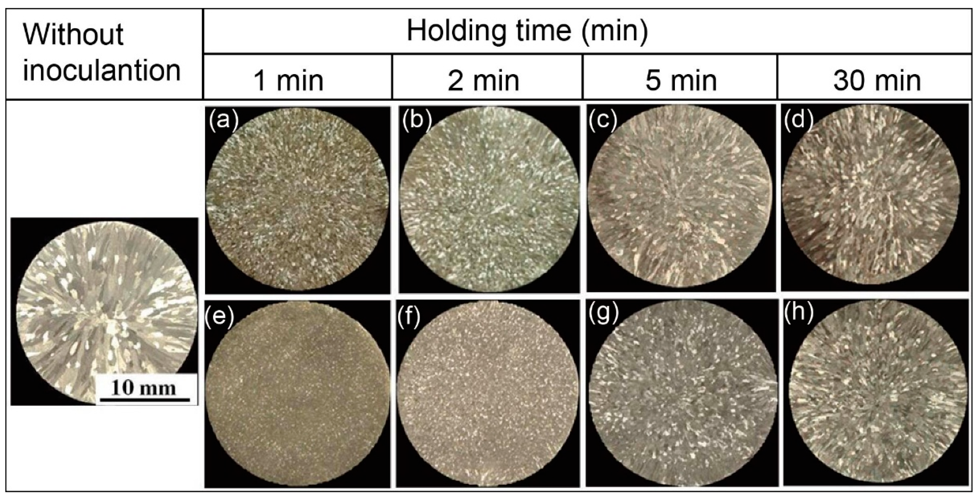
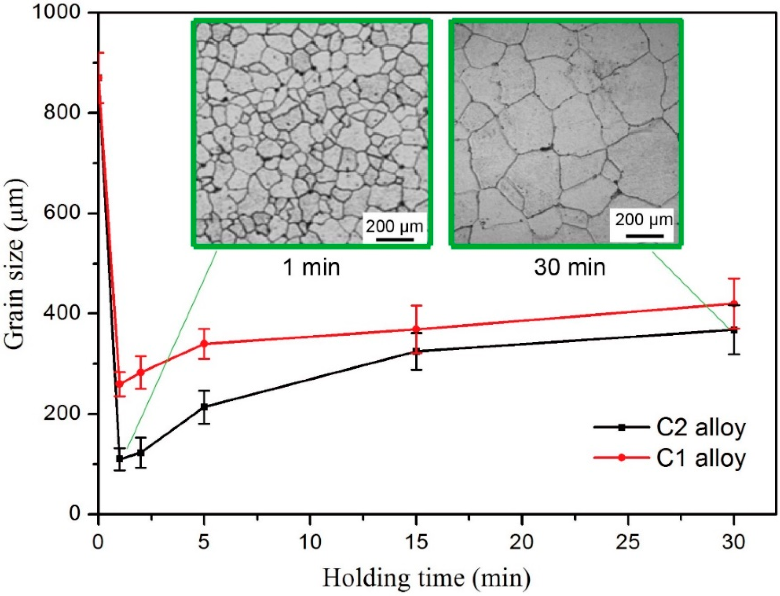
3.3. Effect of Holding Time on Grain Refinement of Melt-Spun Inoculants

Figure 6 presents the microstructure of as-cast pure Al refined by C1 and C2 alloys after different holding time with an addition of 0.4%, which has been verified as the best addition amount previously [25]. The morphology of as-cast Al is usually characterized by coarse dendrites. After adding C1 and C2 alloy, the colossal dendrites of the pure Al are significantly decreased as shown in Figure 6. Meanwhile, it is clear that the refining effect of C2 alloy is better than that of C1 alloy, as the holding time is similar. However, the macro metallographic (Figure 6) shows that the grain refining effect of both inoculants are somewhat decreased as the holding time is increased over 2 min.
Figure 7 displays grain size as a function of holding time of the inoculated samples with both inoculants, which clearly shows the variation tendency of grain refining efficiency. Notably, the samples refined by C2 alloy has relative smaller grain size than that of C1 at a same holding time. As the holding time is over 2 min, both inoculant ribbons show obvious “fading” effect and C2 alloy seemed fading badly. As shown in the inset of Figure 7, for C2 alloy, the grains of the sample with long holding time is about three times bigger than that of short holding time. It is worth of noting that, with very short holding time (1 or 2 min), melt-spun inoculants have the best grain refining effect, and the best holding time is reduced with the increased cooling rate. As well known, melt-spun ribbon is in an unstable and non-equilibrium status due to the fast solidification. Thus, the initial melting of melt-spun ribbon with high cooling rate is different from that of low-cooling-rate alloy, which might relate to the short holding time needed. Nevertheless, the present results show that this inoculant should be used with very short holding time, and it is very important for the future industrial application of this newly developed inoculant.

4. Discussion

Holding time is an important technical parameter for inoculants, which not only determines the detailed casting processing, but also affects the grain refining behavior of refiner particles. In a very short holding time, the inoculant occurs melting at first and begins to interact with the pre-melted Al melt. It is an important phenomenon that the best holding time of C2 alloy is shorter than 2 min, which indicates that the melting behavior of inoculant shows great influence on the refining behavior. It has been found that large cooling rate caused two obvious changes on the inoculant: the supersaturated solid solution of Ce in the α-Al matrix and the miniaturization of CeB6 particles. It is clear that the miniaturization of CeB6 particle will not affect the melting of ribbon, because the melting point of CeB6 is much higher than the holding temperature and CeB6 particles will not melt. Therefore, the melting of the ribbon mainly relates to the supersaturated solid solution of Ce. As shown in Figure 4, the content of cerium in the Al matrix is far more than the theoretical solid solubility of Ce in α-Al on the phase diagram, which is very unstable in thermodynamics. In our opinion, the presence of excess Ce also makes the melting of Al matrix be very unstable at the holding temperature and tend to melt quickly. The sudden and homogeneous melting of ribbons will consume the energy of the Al liquid in the vicinity of the ribbon, and induce an instant large undercooling, which is beneficial for the nucleation of Al upon the surface of CeB6.
As it is known, the grain refining behavior of an inoculant is affected by the following two aspects: the size of refiner particles and the degree of undercooling [31]. According to Quested et al. [31], larger particles take part in the nucleation first (need small undercooling) and smaller particles become inactive due to the recalescence followed by the first nucleation events that increase the temperature in the vicinity of the smaller particles. Therefore, they indicated that the best size of refiner particles is about 400 nm, and the smaller particles require relative large undercooling of which the ordinary casting cannot provided. In this case, the particle size of CeB6 is about ~100 nm, much smaller than the predicted value (400 nm). It can be attributed to the instant large undercooling caused by the fast melting of Al matrix with super saturated Ce.
To explain the refining mechanism, a schematic diagram describing the nucleation and growth process of α-Al dendrites is shown in Figure 8. When the CeB6/Al ribbons is added into pure Al melt, the Al matrix with super saturated Ce element will melt quickly into Ce-rich liquid, and the Ce atoms will fast diffuse in the inoculated melt driven by large concentration gradient. Such fast melting and diffusion processes will suddenly decrease the temperature of the local Al liquid around the unmelted CeB6 particles. Such a process will produce an instant large undercooling, which in turn activates the activity of small particles as nucleated substrate, homogeneously. Then, the inoculated melt is poured into the iron mold which can provide another undercooling, leading to the growth of the pre-nucleated Al crystals to complete the solidification process. When the holding time becomes longer, the undercooling caused by the fast melting of ribbons will disappear, resulting in the “fading” effect of the melt-spun ribbons. For an inference, the inoculants prepared by melt spinning might all require relative short holding time, due to the cooling rate effect according to the above analysis. In addition, the melt-spun CeB6/Al inoculant might be very appropriate for die-casting using iron or copper molds, which can provide a large degree of under cooling to activate the small refiner particles.

5. Conclusions

(1)
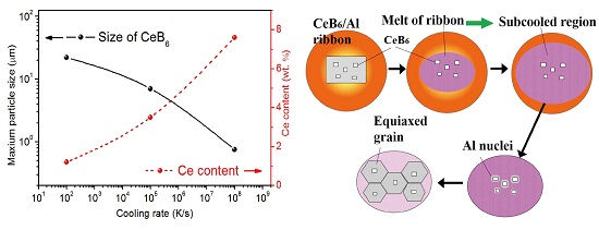
The microstructure, chemical composition, and grain refining effect of CeB6/Al inoculant are all strongly depended on the cooling rate in preparation. With high cooling rate of ~108 K/s, the sizes of CeB6 particles can be reduced to ~100 nm and the content of Ce in Al matrix is obviously increased to form supersaturated Al–Ce solid solution.
(2)
The grain refining efficiency of melt-spun inoculant is strongly dependent on the holding time. The optimum holding time of the inoculation is within 2 min, which is very valuable and crucial for future industrial application.
(3)
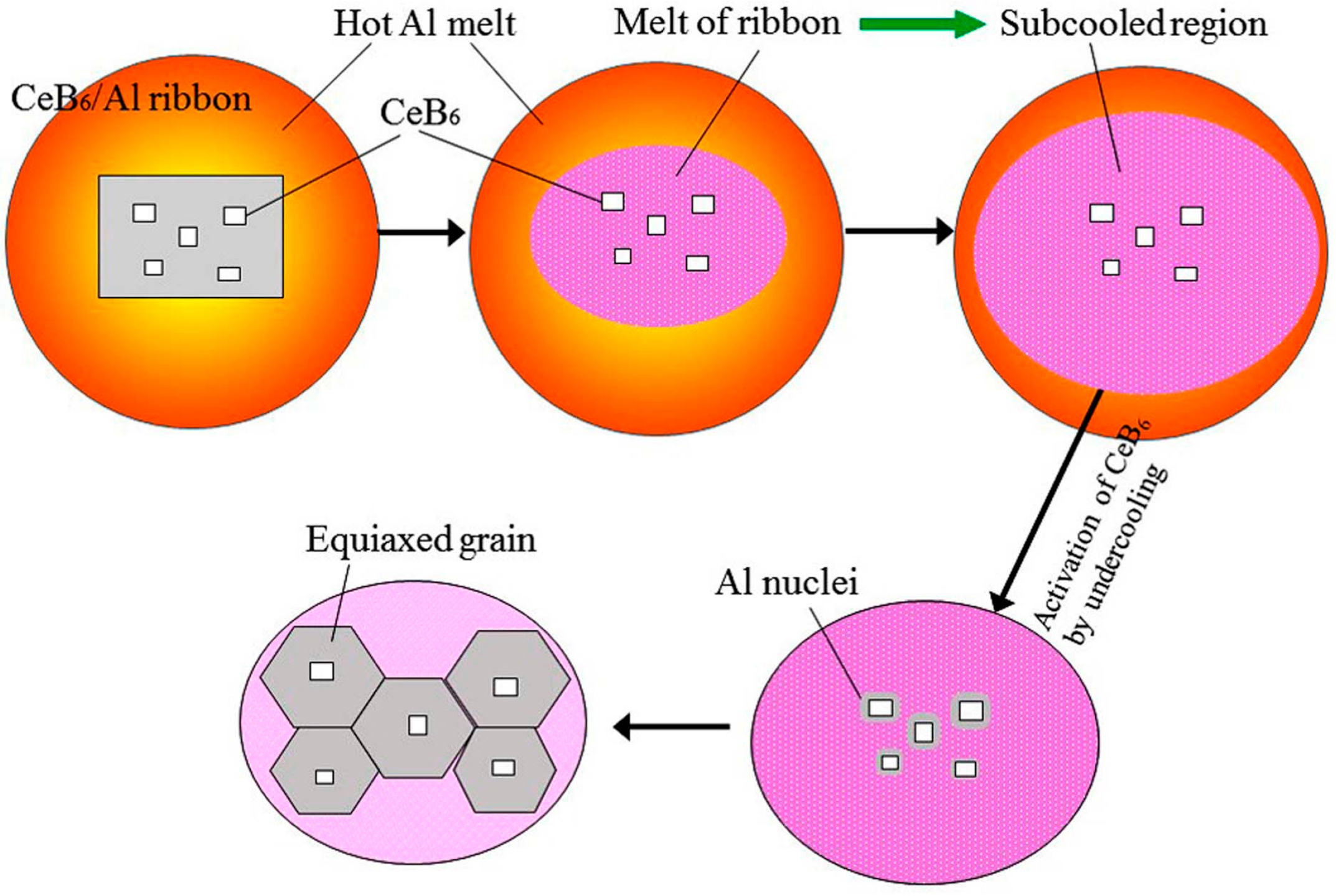
A stationary grain refinement model is proposed to explain the detailed inoculation mechanism of melt-spun CeB6/Al composite inoculant, which agrees well with the very short holding time of CeB6/Al composite inoculant.

Acknowledgments

This work was supported by the Nature Science Foundation of Tianjin (No. 14 JCYBJC17900), Key projects of the Natural Science Foundation of Hebei Province (No. E2013209207 and No. E2016202406) and Graduate Student Innovation Fund Project of Hebei province (No. 220056).

Author Contributions

Shuiqing Liu and Chunxiang Cui conceived and designed the experiments; Shuiqing Liu performed the experiments and wrote the original manuscript; Xin Wang suggested improvement of the experiments and revised the manuscript; Jiejie Shi, Sen Cui, and Peng Chen contributed materials, reagents, and analysis tools, respectively. Nuo Li contributed in revising some grammar and experimental data analysis.

Conflicts of Interest

The authors declare no conflict of interest.

References

  1. Murty, B.S.; Kori, S.A.; Chakraborty, M. Grain refinement of aluminum and its alloys by heterogeneous nucleation and alloying. Int. Mater. Rev. 2002, 47, 3–29. [Google Scholar] [CrossRef]
  2. Easton, M.A.; Stjohn, D.H. A model of grain refinement incorporating alloy constitution and potency of heterogeneous nucleant particles. Acta Mater. 2001, 49, 1867–1878. [Google Scholar] [CrossRef]
  3. Li, Q.L.; Xia, T.D.; Lan, Y.F.; Zhao, W.J.; Fan, L.; Li, P.F. Effect of rare earth cerium addition on the microstructure and tensile properties of hypereutectic Al–20%Si alloy. J. Alloys Compd. 2013, 562, 25–32. [Google Scholar] [CrossRef]
  4. Easton, M.A.; StJohn, D.H. Improved prediction of the grain size of aluminum alloys that includes the effect of cooling rate. Mater. Sci. Eng. A 2008, 486, 8–13. [Google Scholar] [CrossRef]
  5. Verma, A.; Kumar, S.; Grant, P.S.; O’Reilly, K.A.Q. Influence of cooling rate on the Fe intermetallic formation in an AA6063 Al alloy. J. Alloys Compd. 2013, 555, 274–282. [Google Scholar] [CrossRef]
  6. Rajabi, M.; Simchia, A.; Davamia, P. Microstructure and mechanical properties of Al–20Si–5Fe–2X (X=Cu, Ni, Cr) alloys produced by melt-spinning. Mater. Sci. Eng. A 2008, 492, 443–449. [Google Scholar] [CrossRef]
  7. Chen, Z.W.; Lei, Y.M.; Zhang, H.F. Structure and properties of nanostructured A357 alloy produced by melt spinning compared with direct chill ingot. J. Alloys Compd. 2011, 509, 7473–7477. [Google Scholar] [CrossRef]
  8. Dong, T.S.; Cui, C.X.; Liu, S.J.; Yang, L.J.; Sun, J.B. Influence of rapid solidification of Cu–P intermediate alloy on wear resistance of Al–Si alloy. Rare Met. Mater. Eng. 2008, 37, 686–689. [Google Scholar]
  9. Liu, X.B.; Osawa, Y.; Takamori, S.; Mukai, T. Grain refinement of AZ91 alloy by introducing ultrasonic vibration during solidification. Mater. Lett. 2008, 62, 2872–2875. [Google Scholar] [CrossRef]
  10. Quested, T.E.; Dinsdale, A.T.; Greer, A.L. Thermodynamic modelling of growth restriction effects in aluminum alloys. Acta Mater. 2005, 53, 1323–1334. [Google Scholar] [CrossRef]
  11. StJohn, D.H.; Qian, M.; Easton, M.A.; Cao, P. The Interdependence Theory: The relationship between grain formation and nucleant selection. Acta Mater. 2011, 59, 4907–4921. [Google Scholar] [CrossRef]
  12. Quested, T.E.; Greer, A.L. Grain refinement of Al alloys: Mechanisms determining as-cast grain size in directional solidification. Acta Mater. 2005, 53, 4643–4653. [Google Scholar] [CrossRef]
  13. Pineda, D.A.; Martorano, M.A. Columnar to equiaxed transition in directional solidification of inoculated melts. Acta Mater. 2013, 61, 1785–1797. [Google Scholar] [CrossRef]
  14. Dong, X.X.; He, L.J.; Mi, G.B.; Li, P.J. Two directional microstructure and effects of nanoscale dispersed Si particles on microhardness and tensile properties of AlSi7Mg melt-spun alloy. J. Alloys Compd. 2015, 618, 609–614. [Google Scholar] [CrossRef]
  15. Wang, K.; Cui, C.X.; Wang, Q.; Liu, S.J.; Gu, C.S. The microstructure and formation mechanism of core–shell-like TiAl3/Ti2Al20Ce in melt-spun Al–Ti–B–Re grain refiner. Meter. Lett. 2012, 85, 153–156. [Google Scholar] [CrossRef]
  16. Uzun, O.; Karaaslan, T.; Gogebakan, M.; Keskin, M. Hardness and microstructural characteristics of rapidly solidified Al–8–16 wt. % Si alloy. J. Alloys Compd. 2002, 376, 149–157. [Google Scholar] [CrossRef]
  17. Takayama, S. Amorphous structures and their formation and stability. J. Mater. Sci. 1976, 11, 164–185. [Google Scholar] [CrossRef]
  18. Kalay, Y.E.; Chumbley, L.S.; Anderson, I.E.; Napolitano, R.E. Characterization of hypereutectic Al–Si powders solidified under far-from equilibrium conditions. Metall. Mater. Trans. A 2007, 38, 1452–1457. [Google Scholar] [CrossRef]
  19. Xu, C.L.; Wang, H.Y.; Qiu, F.; Yang, Y.F.; Jiang, Q.C. Cooling rate and microstructure of rapidly solidified Al–20 wt. % Si alloy. Mater. Sci. Eng. A 2006, 417, 275–280. [Google Scholar] [CrossRef]
  20. Karaköse, E.; Keskin, M. Effect of solidification rate on the microstructure and microhardness of a melt-spun Al–8Si–1Sb alloy. J. Alloys Compd. 2009, 479, 230–236. [Google Scholar] [CrossRef]
  21. Dong, X.X.; He, L.J.; Li, P.J. Gradient microstructure and multiple mechanical properties of AlSi9Cu alloy ribbon produced by melt spinning. J. Alloys Compd. 2014, 612, 20–25. [Google Scholar] [CrossRef]
  22. Zhang, Z.H.; Bian, X.F.; Wang, Y.; Liu, X.F. Microstructure and grain refining performance of melt-spun Al–5Ti–1B master alloy. Mater. Sci. Eng. A 2003, 352, 8–15. [Google Scholar] [CrossRef]
  23. Tong, X.C.; Fang, H.S. Al–TiC composites In Situ-processed by ingot metallurgy and rapid solidification technology: Part I. Microstructural evolution. Metall. Trans. A 1998, 29, 875–891. [Google Scholar] [CrossRef]
  24. Brochu, M.; Portillo, G. Grain refinement during rapid solidification of aluminum-zirconium alloys using electrospark deposition. Metall. Trans. 2013, 6, 934–939. [Google Scholar] [CrossRef]
  25. Liu, S.Q.; Wang, X.; Cui, C.X.; Zhao, L.C.; Liu, S.J.; Chen, C. Fabrication, microstructure and refining mechanism of in situ CeB6/Al inoculant in aluminum. Mater. Des. 2015, 65, 432–437. [Google Scholar] [CrossRef]
  26. Liu, S.Q.; Wang, X.; Cui, C.X.; Zhao, L.C. Enhanced grain refinement of in situ CeB6/Al composite inoculant on pure aluminum by microstructure control. J. Alloys Compd. 2017, 701, 926–934. [Google Scholar] [CrossRef]
  27. Nie, J.F.; Liu, X.F.; Wu, Y.Y. The influences of B dopant on the crystal structure and nucleation ability of TiCx in the Al melt. Meter. Res. Bull. 2013, 48, 1645–1650. [Google Scholar] [CrossRef]
  28. Wang, K.; Cui, C.X.; Wang, Q.; Qi, Y.M.; Wang, C. Fabrication of in situ AlN–TiN/Al inoculant and its refining efficiency and reinforcing effect on pure aluminum. J. Alloys Compd. 2013, 547, 5–10. [Google Scholar] [CrossRef]
  29. Wang, X.; Gong, P.; Yao, K.F. Mechanical behavior of bulk metallic glass prepared by copper mold casting with reversed pressure. J. Mater. Process Technol. 2016, 237, 270–276. [Google Scholar] [CrossRef]
  30. Sjöberg, L.E. A general model for modifying Stokes’ formula and its least-squares solution. J. Geod. 2003, 77, 459–464. [Google Scholar] [CrossRef]
  31. Quested, T.E.; Greer, A.L. The effect of the size distribution of inoculant particles on as-cast grain size in aluminum alloy. Acta Mater. 2004, 52, 3859–3868. [Google Scholar] [CrossRef]
Figure 1. Temperature versus cooling rate plots of different CeB6/Al inoculant during solidification.
Metals 07 00204 g001
Figure 2. (a) X-ray diffraction (XRD) spectrum of the inoculant alloys with different cooling rates. (b) The enlarged view of XRD spectrum in the (a).
Metals 07 00204 g002
Figure 3. Transmission Electron Microscopy (TEM) characterization of the CeB6/Al ribbon C2.
Metals 07 00204 g003
Figure 4. Scanning electron microscope (SEM) image of (a) C0 alloy, (b) C1 alloy, (c) C2 alloy. (df) are the energy dispersive spectrometer (EDS) spectrum of (ac), respectively.
Metals 07 00204 g004
Figure 5. Cooling rate versus the particles size and the Ce content in the matrix.
Metals 07 00204 g005
Figure 6. Optical metallographic images of as-cast aluminum samples after inoculation with different holding times: (ad) are C1 alloy; (eh) are C2 alloy.
Metals 07 00204 g006
Figure 7. Grain size variations with holding time.
Metals 07 00204 g007
Figure 8. Schematic image showing the nucleation and growth process of α-Al dendrites.
Metals 07 00204 g008
Table 1. Modeling parameters used to estimate the cooling rate [19].
ParametersMaterialMaterial
AlWheel
Initial temperature, T0 (K)1123 (T10)293 (T20)
Thermal conductivity, k (W/(m·K))237 (k1)398 (k2)
Specific heat capacity, c (J/(kg·K))880 (c1)386 (c2)
Density, ρ (kg/m3)2700 (ρ1)8930 (ρ2)
Thermal storage coefficient, b =   k c ρ (W S /(m2·K))23729.98 (b1)37,039 (b2)
Coefficient in Fourier’s equation, α = k/9.59 × 10−5 (α1)-
Latent heat of Al, L (kJ/kg)396.67-
Ribbon–wheel interface temperature Ti = (b1T10 + b2T20)/(b1 + b2) (K)617.11-
Solidus temperature, Ts (K)933.37-
Thickness of the ribbons, χ (μm)--

