
Flat-Top Cylinder Indenter Examination of Duplex Stainless Steel 2205 after Different Heat Treatments


 ,
, 

Abstract
:1. Introduction
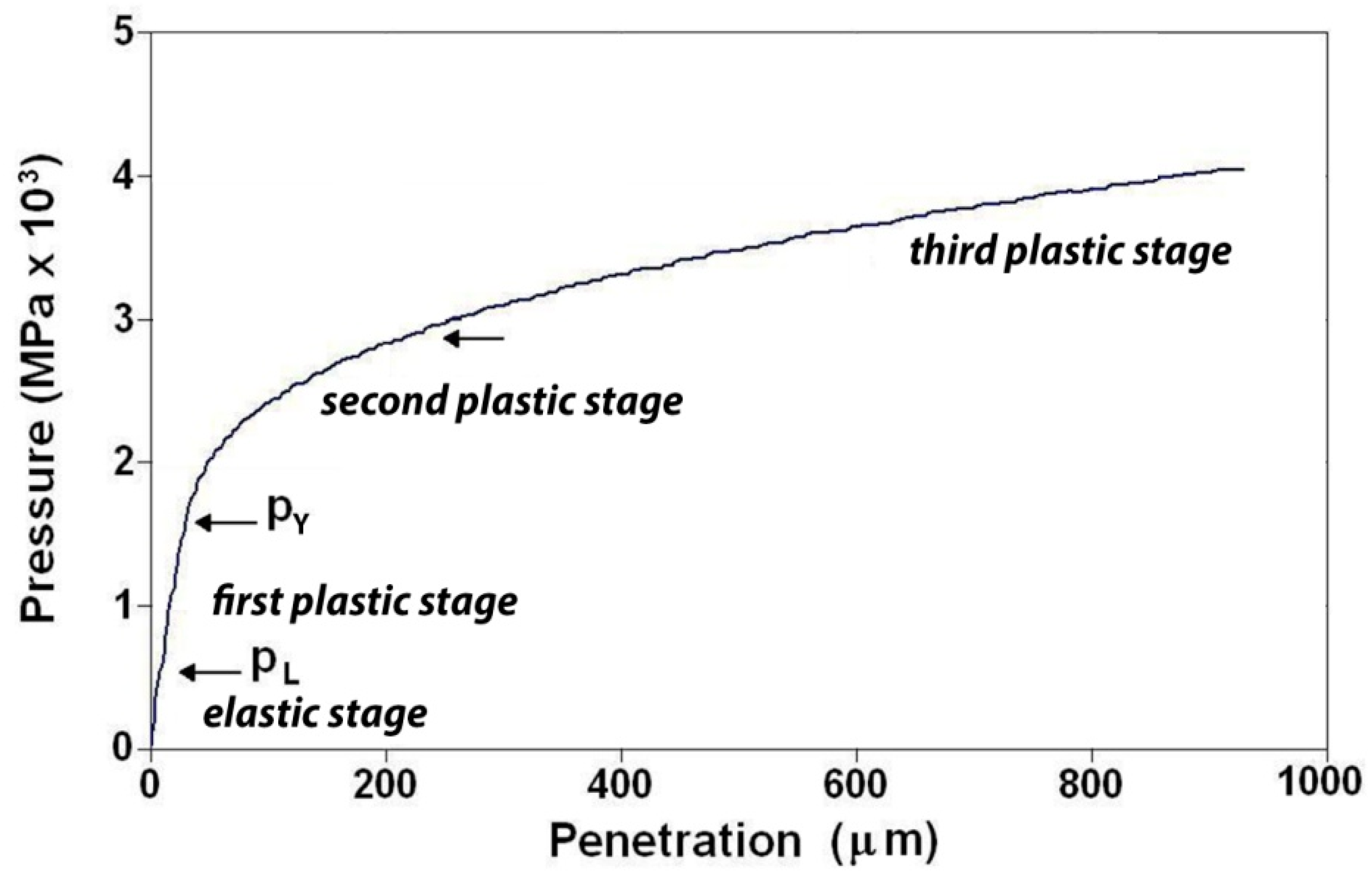
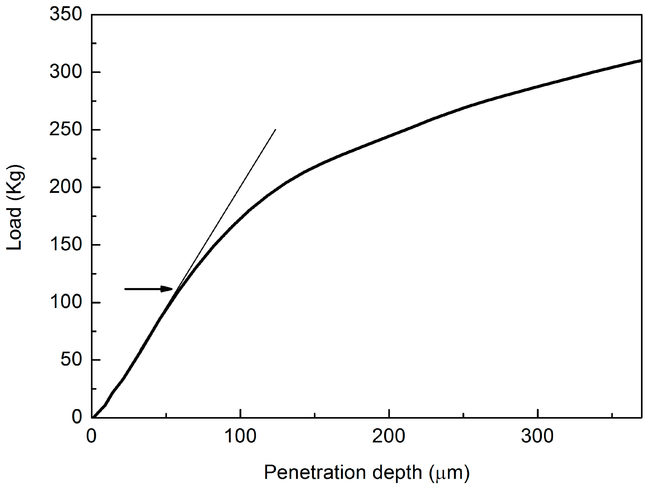
2. The FIMEC Test
3. Material and Experimental Procedure
4. Results
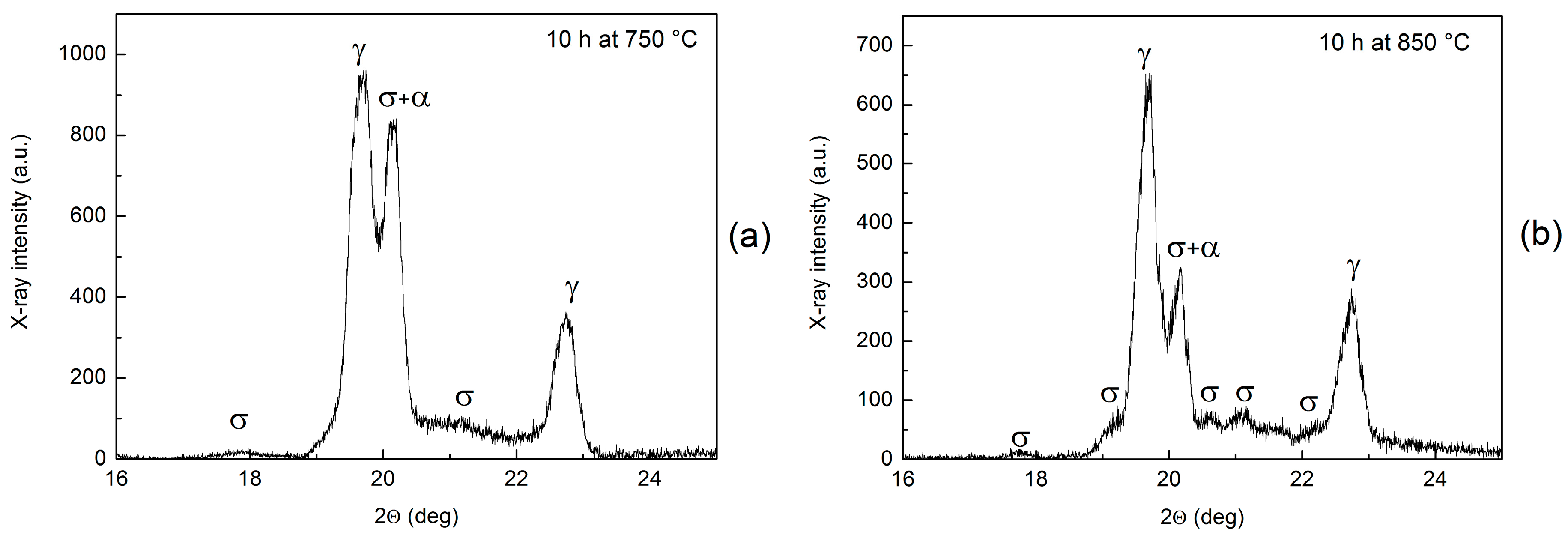
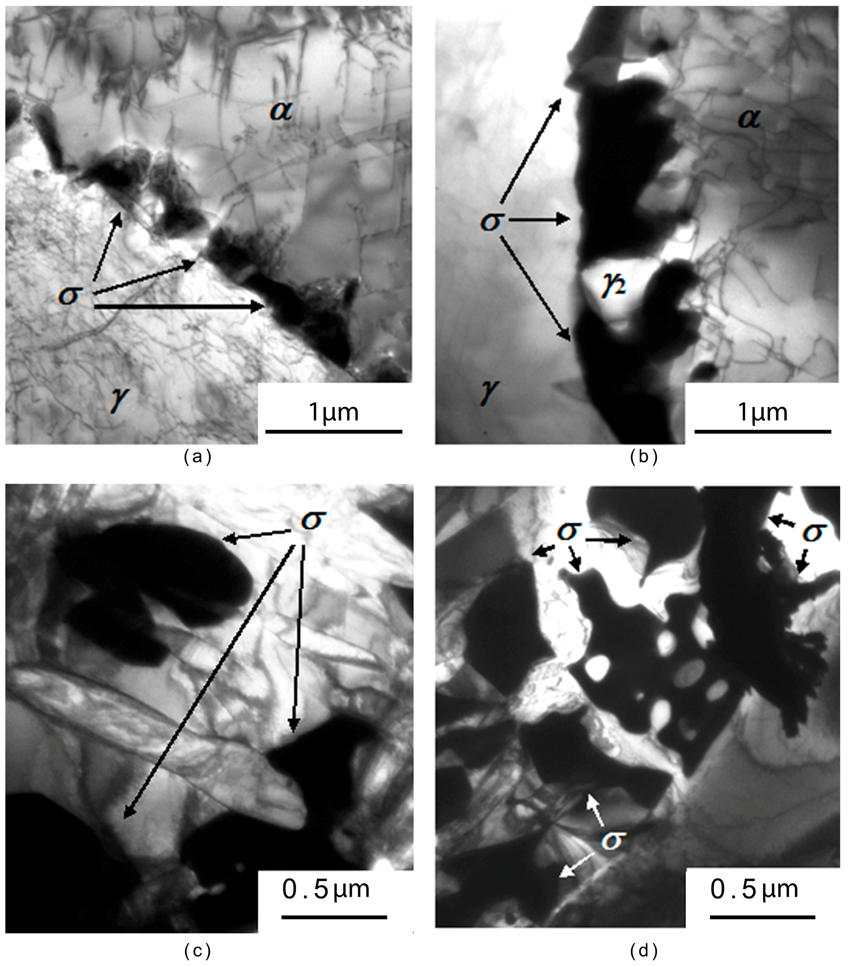
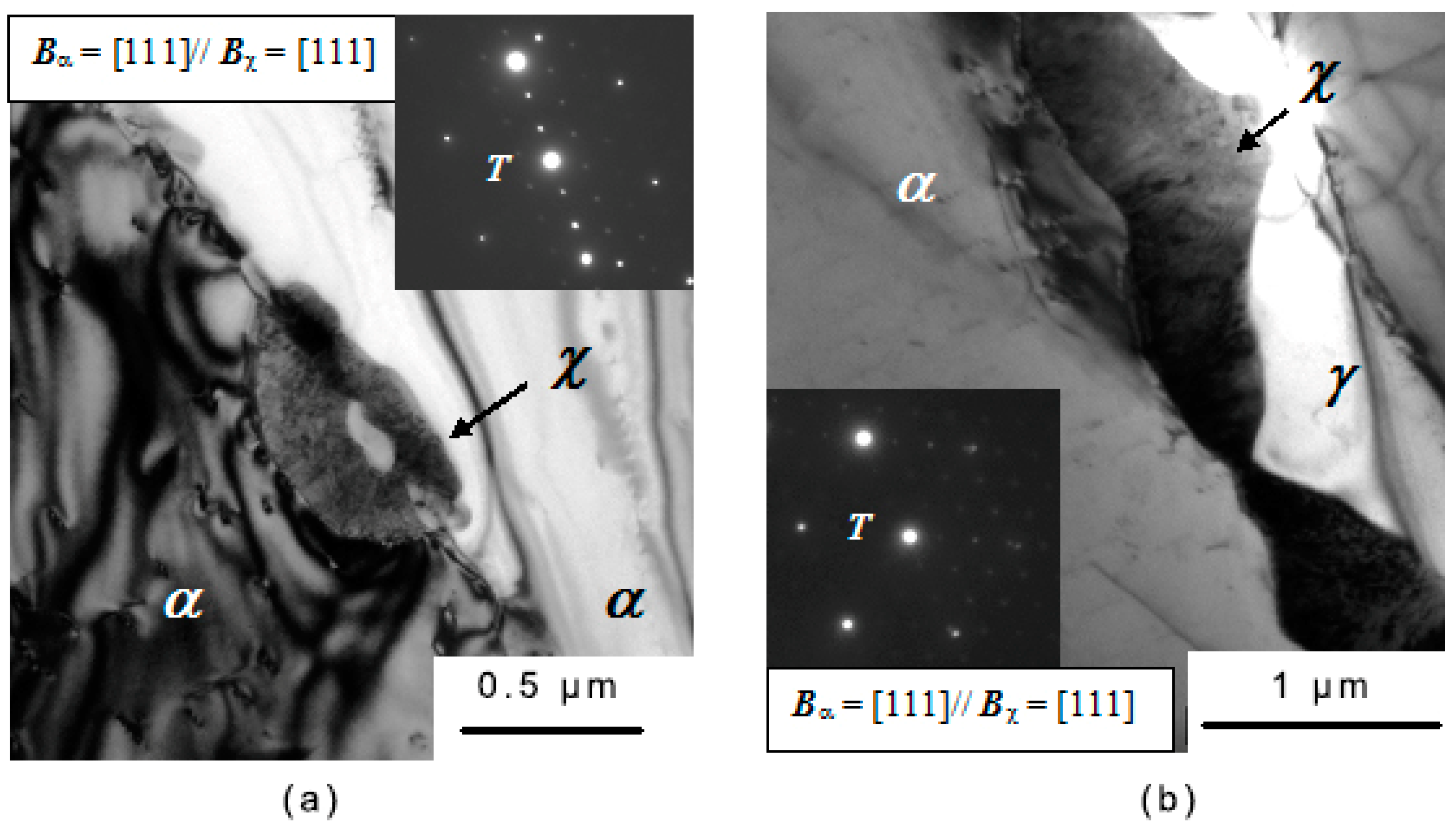
4.1. Microstructure Characterization
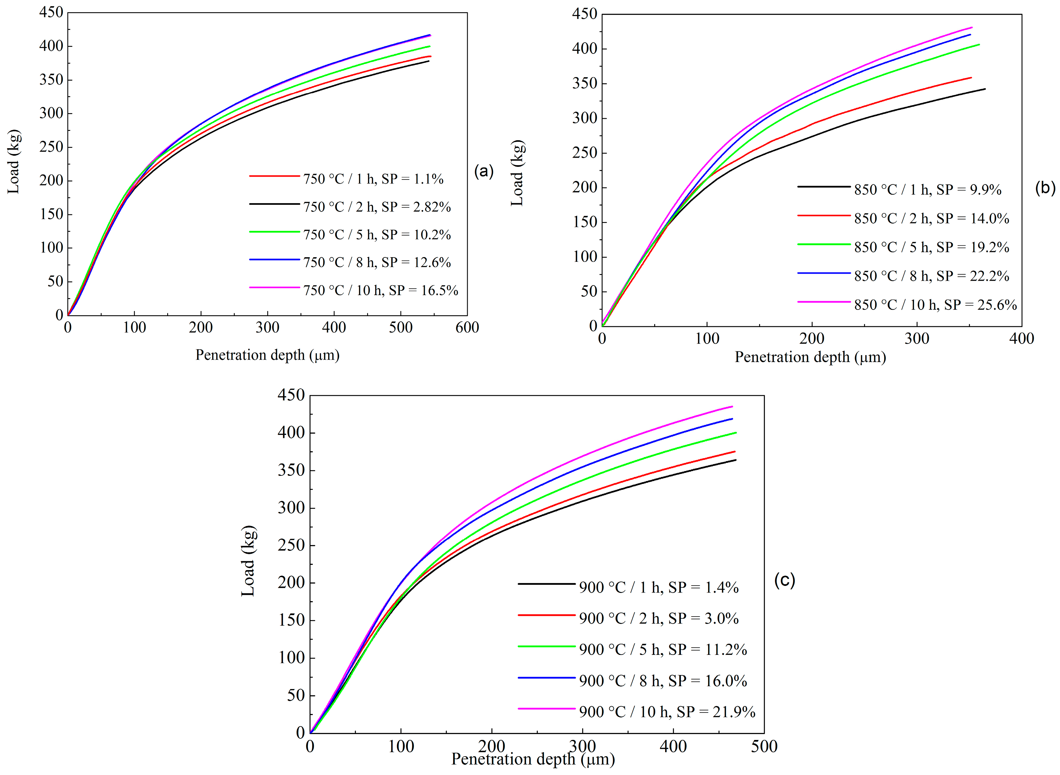
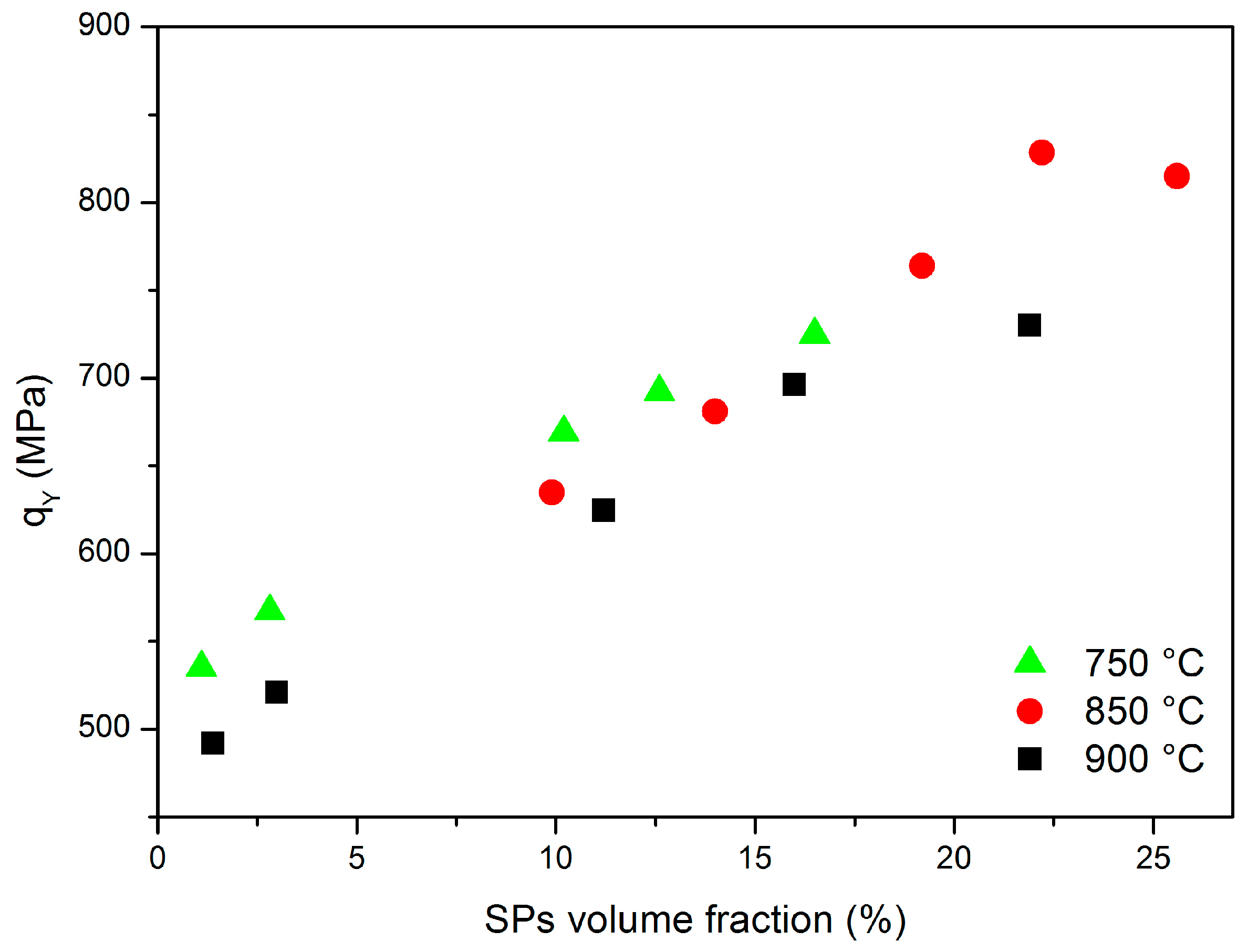
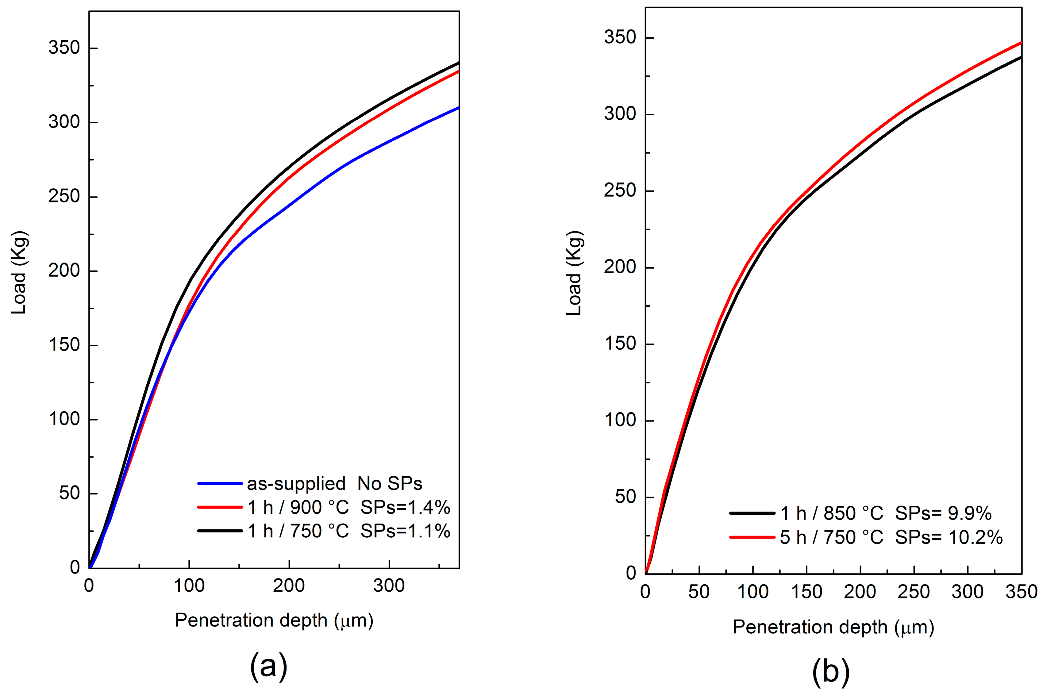
4.2. FIMEC Results
5. Discussion
6. Conclusions
- FIMEC is capable of detecting changes of yield stress induced by the precipitation of small SP amounts (~1%);
- It is also sensitive to the specific σ phase morphology (“coral-like” or bulky structures).
Author Contributions
Conflicts of Interest
References
- Solomon, H.D.; Devine, T.M. Duplex Stainless Steels—A tale of two phases. In Proceedings of the Conference on Duplex Stainless Steels, St. Louis, MO, USA, 23–28 October 1982; pp. 693–756. [Google Scholar]
- Capello, E.; Chiarello, P.; Previtali, B.; Vedani, M. Laser welding and surface treatment of a 22Cr-5Ni-3Mo duplex stainless steel. Mater. Sci. Eng. A 2003, 351, 334–343. [Google Scholar] [CrossRef]
- Karlsson, L.; Bengtsson, L.; Rolander, U.; Pak, S. The kinetics of intermetallic phase formation in duplex stainless weld metals and their influence on mechanical properties. In Proceedings of the Applications of Stainless Steels, Stockholm, Sweden, 9–11 June 1992; pp. 335–344. [Google Scholar]
- Fargas, G.; Anglada, M.; Mateo, A. Effect of the annealing temperature on the mechanical properties, formability and corrosion resistance of hot-rolled duplex stainless steel. J. Mater. Process. Technol. 2009, 209, 1770–1782. [Google Scholar] [CrossRef]
- Ahn, Y.S.; Kang, J.P. Effect of aging treatments on microstructure and impact properties of tungsten substituted 2205 duplex stainless steel. Mater. Sci. Technol. 2000, 16, 382–388. [Google Scholar] [CrossRef]
- Chen, T.H.; Yang, J.R. Effects of solution treatment and continuous cooling on σ-phase precipitation in a 2205 duplex stainless steel. Mater. Sci. Eng. A 2001, 311, 28–41. [Google Scholar] [CrossRef]
- Chen, T.H.; Weng, K.L.; Yang, J.R. The effect of high-temperature exposure on the microstructural stability and toughness property in a 2205 duplex stainless steel. Mater. Sci. Eng. A 2002, 338, 259–270. [Google Scholar] [CrossRef]
- El Koussy, M.R.; El Mahallawi, I.S.; Khalifa, W.; Al Dawood, M.M.; Bueckins, M. Effect of thermal aging on microstructure and mechanical properties of duplex stainless steel weldments. Mater. Sci. Technol. 2004, 20, 375–381. [Google Scholar] [CrossRef]
- Nowacki, J.; Rybicki, P. The influence of welding heat input on submerged arc welded duplex steel joints imperfections. J. Mater. Proc. Technol. 2005, 164, 1082–1088. [Google Scholar] [CrossRef]
- Badji, R.; Bouabdallah, M.; Bacroix, B.; Kahloun, C.; Belkessa, B.; Maza, H. Phase transformation and mechanical behavior in annealed 2205 duplex stainless steel welds. Mater. Charact. 2008, 59, 447–453. [Google Scholar]
- Chan, K.W.; Tjong, S.C. Effect of Secondary Phase Precipitation on the Corrosion Behavior of Duplex Stainless Steels. Materials 2014, 7, 5268–5304. [Google Scholar] [CrossRef]
- Calliari, I.; Pellizzari, M.; Zanellato, M.; Ramous, E. The phase stability in Cr-Ni and Cr-Mn duplex stainless steels. J. Mater. Sci. 2011, 46, 6916–6924. [Google Scholar] [CrossRef]
- Karlsson, L.; Rigdal, S.; Lake, F. Effects of intermetallic phases in duplex stainless steel weldments. In Proceedings of the Duplex America 2000 Conference on Duplex Stainless Steel, Houston, TX, USA, 29 February–1 March 2000; pp. 257–272. [Google Scholar]
- Pohl, M.; Storz, O.; Glogowski, T. Effect of intermetallic precipitations on the properties of duplex stainless steel. Mater. Charact. 2007, 58, 65–71. [Google Scholar] [CrossRef]
- Haghdadi, N.; Abou-Ras, D.; Cizek, P.; Hodgson, P.D.; Rollett, A.D.; Beladi, H. Austenite-ferrite interface crystallography dependence of sigma phase precipitation using the five-parameter characterization approach. Mater. Lett. 2017, 196, 264–268. [Google Scholar] [CrossRef]
- Calliari, I.; Zanesco, M.; Ramous, E. Influence of isothermal aging on secondary phases precipitation and toughness of a duplex stainless steel SAF 2205. J. Mater. Sci. 2006, 41, 7643–7649. [Google Scholar] [CrossRef]
- Lee, K.M.; Cho, H.S.; Choi, D.C. Effect of isothermal treatment of SAF 2205 duplex stainless steel on migration of δ/γ interface boundary and growth of austenite. J. Alloys Compd. 1999, 285, 156–161. [Google Scholar] [CrossRef]
- Sieurin, H.; Sandstrom, R. Sigma phase precipitation in duplex stainless steel 2205. Mater. Sci. Eng. A 2007, 444, 271–276. [Google Scholar] [CrossRef]
- Kim, Y.J.; Chumbley, L.S.; Gleeson, B. Continuous cooling transformation in cast duplex stainless steels CD3MN and CD3MWCuN. J. Mater. Eng. Perform. 2008, 17, 234–239. [Google Scholar] [CrossRef]
- Ferro, P. A dissolution kinetics model and its application to duplex stainless steels. Acta Mater. 2013, 61, 3141–3147. [Google Scholar] [CrossRef]
- Ferro, P.; Bonollo, F. A Semiempirical Model for Sigma-Phase Precipitation in Duplex and Superduplex Stainless Steels. Metall. Mater. Trans. A 2012, 43, 1109–1116. [Google Scholar] [CrossRef]
- Caluscio Dos Santos, D.; Magnabosco, R. Kinetic Study to Predict Sigma Phase Formation in Duplex Stainless Steels. Metall. Mater. Trans. A 2016, 47, 1554–1565. [Google Scholar] [CrossRef]
- Warren, A.D.; Harniman, R.L.; Guo, Z.; Younes, C.M.; Flewitt, P.E.J.; Scot, T.B. Quantification of sigma-phase evolution in thermally aged 2205 duplex stainless steel. J. Mater. Sci. 2016, 51, 694–707. [Google Scholar] [CrossRef]
- Gondi, P.; Donato, A.; Montanari, R.; Sili, A. A miniaturized test method for the mechanical characterization of structural materials for fusion reactors. J. Nucl. Mater. 1996, 233, 1557–1560. [Google Scholar] [CrossRef]
- Donato, A.; Gondi, P.; Montanari, R.; Moreschi, F.; Sili, A.; Storai, S. A remotely operated FIMEC apparatus for the mechanical characterization of neutron irradiated materials. J. Nucl. Mater. 1998, 258, 446–451. [Google Scholar] [CrossRef]
- Riccardi, B.; Montanari, R.; Moreschi, L.F.; Sili, A.; Storai, S. Mechanical characterization of fusion materials by indentation test. Fusion Eng. Des. 2001, 58, 755–759. [Google Scholar] [CrossRef]
- Riccardi, B.; Montanari, R. Indentation of metals by flat-ended cylindrical punch. Mater. Sci. Eng. A 2004, 381, 281–291. [Google Scholar] [CrossRef]
- Montanari, R.; Filacchioni, G.; Riccardi, B.; Tata, M.E.; Costanza, G. Characterization of Eurofer-97 TIG-welded joints by FIMEC indentation tests. J. Nucl. Mater. 2004, 329, 1529–1533. [Google Scholar] [CrossRef]
- Balijepalli, S.K.; Colanoni, I.; Donnini, R.; Kaciulis, S.; Lucci, M.; Montanari, R.; Ucciardello, N.; Varone, A. Elastic modulus of the S phase in a kolsterized 316L stainless steel. La Metall. Ital. 2013, 105, 42–47. [Google Scholar]
- Balijepalli, S.K.; Donnini, R.; Kaciulis, S.; Montanari, R.; Varone, A. Young’s modulus profile in kolsterized AISI 316L steel. Mater. Sci. Forum 2013, 762, 183–188. [Google Scholar] [CrossRef]
- Rotundo, F.; Ceschini, L.; Martini, C.; Montanari, R.; Varone, A. High temperature tribological behavior and microstructural modifications of the low-temperature carburized AISI 316L austenitic stainless steel. Surf. Coat. Technol. 2014, 258, 772–781. [Google Scholar] [CrossRef]
- Sola, R. Post-treatment surface morphology effect on the wear and corrosion resistance of nitrided and nitrocarburized 41 CrAlMo7 steel. La Metall. Ital. 2010, 102, 21–31. [Google Scholar]
- Sola, R.; Poli, G.; Giovanardi, R.; Veronesi, P.; Calzolari, C.; Zanotti, A. Wear and corrosion resistance modification of nitrided and nitrocarburized steeels. La Metall. Ital. 2010, 102, 29–39. [Google Scholar]
- Montanari, R.; Varone, A.; Barbieri, G.; Soltani, P.; Mezzi, A.; Kaciulis, S. Welding of IN792 DS superalloy by electron beam. Surf. Interface Anal. 2016, 48, 483–487. [Google Scholar] [CrossRef]
- Sathirachinda, N.; Pettersson, R.; Pan, J. Depletion effects at phase boundaries in 2205 duplex stainless steel characterized with SKPFM and TEM/EDS. Corros. Sci. 2009, 51, 1850–1860. [Google Scholar] [CrossRef]
- Zucato, I.; Moreira, M.C.; Machado, I.F.; Lebrao, S.M.G. Microstructural characterization and the effect of phase transformations on toughness of the UNS S31803 duplex stainless steel aged treated at 850 °C. Mater. Res. 2002, 5, 385–389. [Google Scholar] [CrossRef]
- Gregori, A.; Nilson, J.O. Decomposition of ferrite in commercial superduplex stainless steel weld metals; microstructural transformations above 700 °C. Metall. Mater. Trans. A 2002, 33, 1009–1018. [Google Scholar] [CrossRef]
- Ramirez, A.J.; Lipold, J.C.; Brandi, S.D. The relationship between chromium nitride and secondary austenite precipitation in duplex stainless steels. Metall. Mater. Trans. A 2003, 34, 1575–1597. [Google Scholar] [CrossRef]
- Michalska, J.; Sozanska, M. Qualitative and quantitative analysis of σ and χ phases in 2205 duplex stainless steel. Mater. Charact. 2006, 56, 355–362. [Google Scholar] [CrossRef]
- Escriba, D.M.; Materna-Morris, E.; Plaut, R.L.; Padilha, A.F. Chi-phase precipitation in a duplex stainless steel. Mater. Charact. 2009, 60, 1214–1219. [Google Scholar] [CrossRef]
- Badji, R.; Bouabdallah, M.; Bacroix, B.; Kahloun, C.; Bettahar, K.; Kherrouba, N. Effect of solution treatment temperature on the precipitation kinetic of σ-phase in 2205 duplex stainless steel welds. Mater. Sci. Eng. A 2008, 496, 447–454. [Google Scholar] [CrossRef]
- Cvijovic´, Z.; Radenkovic´, G. Microstructure and pitting corrosion resistance of annealed duplex stainless steel. Corros. Sci. 2006, 48, 3887–3906. [Google Scholar] [CrossRef]
- Redjaїmia, A.; Proult, A.; Donnadieu, P. Morphology, crystallography and defects of the intermetallic χ-phase precipitated in a duplex (δ + γ) stainless steel. J. Mater. Sci. 2004, 39, 2371–2386. [Google Scholar] [CrossRef]
- Nilsson, J.-O.; Huhtala, T.; Jonsson, P.; Karlsson, L.; Wilson, A. Structural stability of super duplex stainless weld metals and its dependence on tungsten and copper. Metall. Mater. Trans. A 1996, 27, 2196–2208. [Google Scholar] [CrossRef]
- Nilsson, J.O.; Kangas, P.; Karlsson, T.; Wilson, A. Mechanical properties, microstructural stability and kinetics of σ-phase formation in 29Cr-6Ni-2Mo-0.38N superduplex stainless steel. Metall. Mater. Trans. A 2000, 31, 35–45. [Google Scholar] [CrossRef]
- Akisanya, A.R.; Obi, U.; Renton, N.C. Effect of ageing on phase evolution and mechanical properties of high tungsten super-duplex stainless steel. Mater. Sci. Eng. A 2012, 535, 281–289. [Google Scholar] [CrossRef]


| T (°C) | 750 | 850 | 900 | ||||||||||||
|---|---|---|---|---|---|---|---|---|---|---|---|---|---|---|---|
| t (h) | 1 | 2 | 5 | 8 | 10 | 1 | 2 | 5 | 8 | 10 | 1 | 2 | 5 | 8 | 10 |
| α grain size (μm) | 23 | 20 | 10 | 10 | 8 | 15 | 10 | 8 | 5 | - | 20 | 17 | 8 | 5 | 4 |
| γ grain size (μm) | 70 | 75 | 82 | 85 | 90 | 75 | 80 | 88 | 93 | 99 | 72 | 76 | 85 | 87 | 92 |
| α (%) | 45.0 | 33.0 | 22.9 | 20.5 | 17.4 | 34.0 | 26.0 | 13.2 | 4.4 | 0 | 38.0 | 30.0 | 21.0 | 12.0 | 4.0 |
| γ (%) | 53.9 | 64.2 | 66.9 | 66.9 | 66.1 | 56.1 | 60.0 | 67.6 | 73.4 | 74.4 | 60.6 | 67.0 | 67.8 | 72.0 | 74.1 |
| SPs (%) | 1.1 | 2.8 | 10.2 | 12.6 | 16.5 | 9.9 | 14.0 | 19.2 | 22.2 | 25.6 | 1.4 | 3.0 | 11.2 | 16.0 | 21.9 |
| Sdv | 0.3 | 0.4 | 0.9 | 1.0 | 1.2 | 0.9 | 1.2 | 1.3 | 1.6 | 1.7 | 0.2 | 0.4 | 0.9 | 1.2 | 1.4 |
| T (°C) | 750 | 850 | 900 | ||||||||||||
|---|---|---|---|---|---|---|---|---|---|---|---|---|---|---|---|
| t (h) | 1 | 2 | 5 | 8 | 10 | 1 | 2 | 5 | 8 | 10 | 1 | 2 | 5 | 8 | 10 |
| qy (MPa) | 535 | 567 | 669 | 692 | 725 | 635 | 681 | 764 | 828 | 815 | 492 | 521 | 624 | 696 | 730 |
| HV | 253 | 262 | 279 | 301 | 320 | 278 | 310 | 329 | 340 | 352 | 256 | 264 | 285 | 310 | 340 |
| SPs (%) | 1.1 | 2.82 | 10.2 | 12.6 | 16.5 | 9.9 | 14.0 | 19.2 | 22.2 | 25.6 | 1.4 | 3.0 | 11.2 | 16.0 | 21.9 |
© 2017 by the authors. Licensee MDPI, Basel, Switzerland. This article is an open access article distributed under the terms and conditions of the Creative Commons Attribution (CC BY) license (http://creativecommons.org/licenses/by/4.0/).
Share and Cite
Angella, G.; Fava, A.; Montanari, R.; Richetta, M.; Varone, A. Flat-Top Cylinder Indenter Examination of Duplex Stainless Steel 2205 after Different Heat Treatments. Metals 2017, 7, 178. https://doi.org/10.3390/met7050178
Angella G, Fava A, Montanari R, Richetta M, Varone A. Flat-Top Cylinder Indenter Examination of Duplex Stainless Steel 2205 after Different Heat Treatments. Metals. 2017; 7(5):178. https://doi.org/10.3390/met7050178
Chicago/Turabian StyleAngella, Giuliano, Alessandra Fava, Roberto Montanari, Maria Richetta, and Alessandra Varone. 2017. "Flat-Top Cylinder Indenter Examination of Duplex Stainless Steel 2205 after Different Heat Treatments" Metals 7, no. 5: 178. https://doi.org/10.3390/met7050178
APA StyleAngella, G., Fava, A., Montanari, R., Richetta, M., & Varone, A. (2017). Flat-Top Cylinder Indenter Examination of Duplex Stainless Steel 2205 after Different Heat Treatments. Metals, 7(5), 178. https://doi.org/10.3390/met7050178