Article

Tribological Properties of Plough Shares Made of Pearlitic and Martensitic Steels

by
Tomasz Stawicki
1,
Beata Białobrzeska
2,* and
Piotr Kostencki
1
1
Department of Agrotechnical Systems Engineering, Faculty of Environmental Management and Agriculture, West Pomeranian University of Technology, Papieża Pawła VI Street 1, 71-459 Szczecin, Poland
2
Welding and Strength of Materials, Department of Materials Science, Faculty of Mechanical Engineering, Wroclaw University of Technology, Smoluchowskiego Street 25, 50-370 Wrocław, Poland
*
Author to whom correspondence should be addressed.
Metals 2017, 7(4), 139; https://doi.org/10.3390/met7040139
Submission received: 11 March 2017 / Revised: 5 April 2017 / Accepted: 11 April 2017 / Published: 14 April 2017
(This article belongs to the Special Issue Alloy Steels)

Abstract

:
Tribological properties of ploughshares made of pearlitic and martensitic steels were compared in field tests. Sectional ploughshares consisting of separate share-points and trapezoidal parts were subjected to examinations. Contours of the examined parts were similar, but the thickness of the parts made of pearlitic steel was 1 to 3 mm greater for the share-points and 0.5 to 2 mm greater for the trapezoidal parts. Within the tests, sandy loams, loams, and loamy sands with circa (ca.) 13% humidity were cultivated. A greater intensity of thickness reduction and mass wear of the parts made of pearlitic steel was found, which indicates a lower resistance of this steel to wear in soil. However, contour changes of the share-points and the trapezoidal parts made of pearlitic and martensitic steels were comparable, which was probably influenced by the greater thickness of the parts made of pearlitic steel. The roughness of the rake faces of the parts made of pearlitic steel was greater than that for the parts made of martensitic steel, which can be attributed to lower hardness of the former. The largest differences occurred between maximum peak heights of the roughness profile values (Rp), which indicates stronger ridging in the case of pearlitic steel. Scanning electron microscope (SEM) observations of the rake faces showed that martensitic steel was subjected to wear mostly by microcutting, but pearlitic steel was principally worn by microcutting and microploughing. During tillage, only one share-point made of pearlitic steel was broken. However, the main disadvantage of these parts was that their bending was related to the lower mechanical strength of pearlitic steel.

1. Introduction

Tillage still belongs to popular operations of soil cultivation and this indicates a need to carry out research aimed at the improvement of the design solutions of ploughshares. Ploughshares, like many other parts working in soil, are subjected during operation to intensive abrasion wear [1,2,3] that results in a change in their geometry and a reduction of mass. In consequence, after reaching the so-called ultimate limit state, these components must be replaced with new ones. Thus, users of agricultural equipment expect that the manufacturers offer durable replacement parts. The economic aspect, i.e., the low price of the products, is also significant.
In spite of many years of laboratory and field research, wear of the parts operating in soil (including ploughshares) constitutes a still valid tribological and operating problem, because of the complexity of the mechanisms occurring in these processes. The research performed so far includes, among others, an evaluation of the relation between wear processes and the geometry of particles composing abrasive soil mass, as well as the physico-chemical conditions of the working environment, described by the granulometric composition of soil, its humidity and consistency, the content of skeleton particles, reactions, etc. [4,5,6,7]. As far as humidity alone is concerned, its diversified influence on the wear dynamics of ploughshares has been demonstrated. It was observed that, with increasing soil humidity, the wear rate of ploughshares is lower in loamy and clay soils, but is higher in sandy soils [5,8,9]. In soils with low humidity, the intensive wear of ploughshares was observed on their flank faces, which resulted in a relatively quick reduction in the length of their share-points and in the width of their trapezoidal parts. On the other hand, in soils with high humidity, a relatively quick thickness reduction in shares has been found [10,11]. The complexity of the wear mechanisms of the parts operating in soil is also shown by the research in that a relation between the wear rate of steel and the reaction of the working environment has been demonstrated [12,13].
Users of agricultural equipment have no effect on most of the factors related to the operating conditions of tillage tools, but are interested in a long durability of the working parts. The relatively well-known and still-in-development methods that of improving the durability of ploughshares include pad-welding with hard alloys in the areas subjected to intensive wear. The effectiveness of this solution has been confirmed in laboratories and field research many times [14,15,16,17,18]. Research on the anti-wear properties of steels containing micro-additions of boron (e.g., steels Hardox, Raex, SSAB Boron 33) and steels surface-hardened by diffusive boriding [19,20,21] have been undertaken. The possibility of using oxide ceramics and plates made of sintered carbides as abrasion-resistant superficial layers of the components operating in soil has also been considered [22,23,24,25,26]. It should also be mentioned that a beneficial economic effect of plough cultivation can be reached by using sectional ploughshares, currently offered by several manufacturers. Such a solution makes it possible to utilize the trapezoidal parts of shares more completely [11].
The present research was aimed at comparing tribological properties of ploughshares made of pearlitic and martensitic steels, while the starting material for the manufacture of pearlitic shares were railway rails withdrawn from use, being a cheap base material.

2. Materials and Methods

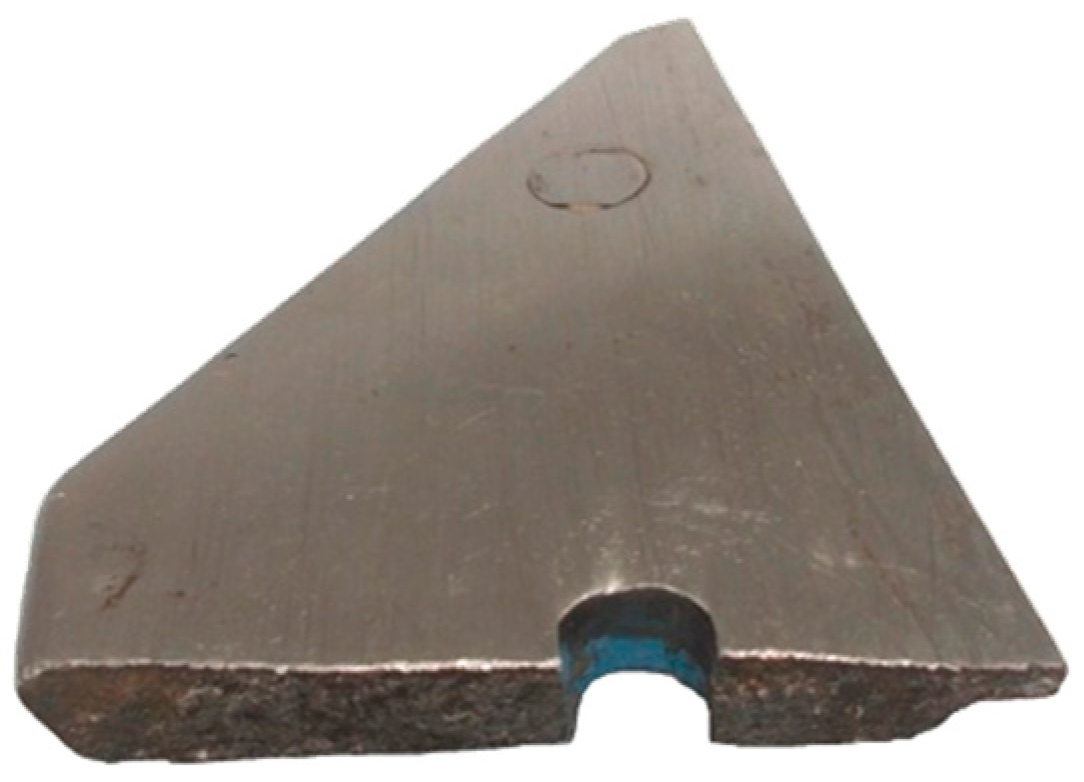
2.1. Objects of the Research

Two variants of ploughshares were used in the research, differing basically in properties of the used steels. One of the steels was characterized by a martensitic structure (shares from a well-known manufacturer of agricultural tooling), and the other steel by a pearlitic structure (shares from a manufacturer that utilizes recycled railway rails). It should be mentioned that the usefulness of the shares made of pearlitic steel is not well recognized. However, the shares made of martensitic steel, used in this research, are renowned, and this is why they were selected as reference objects. In both variants, the shares were sectioned, i.e., composed of separate share-points and trapezoidal parts.
The chemical composition of the steels used for the examined ploughshares was determined by spectral analysis using a glow discharge spectrometer GDS500A (Leco Corporation, Saint Joseph, MO, USA). The examined material was placed under atmosphere low-pressure argon. A negative potential between 800 and 1200 V was applied to the specimens. Results are given in Table 1.
Microscopic examinations were carried out on cross sections of steel specimens etched with 3% HNO3 (according to PN-H-04512-1975) at magnifications between 100 and 500×. Observations were made using a metallographic microscope (Nikon Corporation, Tokyo, Japan) coupled with a charge-coupled device (CCD) camera. The structure of the ploughshares made of railway rails was found to be pearlitic (non-homogeneous in some places) with ferrite crystallized on grain boundaries of former austenite. Moreover, numerous inclusions were observed, probably sulfides, see Figure 1a,b. The structure of the reference shares was found to be martensitic, composed of medium-carbon and fine-acicular tempered martensite, see Figure 1c.
For the steels under examination, hardness, impact strength, tensile strength, proof stress, and ultimate elongation were determined. Brinell hardness was measured according to EN ISO 6506-1:2014-12 using a Zwick/Roell tester (Zwick Roell Gruppe, Ulm, Germany), under 187.5 kG (1839 N) for 15 s. Charpy V-notch tests were carried out according to EN ISO 67 148-1:2010 at ambient temperature, on the Zwick Roell pendulum hammer RPK300 (Zwick Roell Gruppe, Ulm, Germany) on specimens with dimensions b = 10 mm × h = 7.5 mm, cut out in longitudinal and perpendicular directions in relation to the plastic working direction. Fracture surfaces of the specimens were analyzed using a scanning electron microscope JEOL JSM-5800LV (Joel Ltd., Tokyo, Japan) coupled with an X-ray analyzer, Oxford LINK ISIS-300 (Oxford Instruments, Abingdon, UK). Tensile tests were carried out according to EN ISO 6892-1:2016-09 on a tester MTS 810 (MTS Systems, Eden Prairie, MN, USA) using flat specimens 40 mm long, with a cross section with a gauge length of 5 × 10 mm. The specimens were cut-out from trapezoidal parts of the ploughshares along their length. Results of the measurements and tests are given in Table 2.
Microscopic analysis of fracture surfaces obtained in impact tests showed 100% of the brittle zone for pearlitic steel, but significant plastic zones in the side parts for martensitic steel, see Figure 2a–d.
Specimens of pearlitic steel showed cleavage fractures with fragments of plastic fracture between the facets, with characteristic profiles of “rivers”, see Figure 2e–h. In the places where cracks propagated through grain boundaries, “fan” profiles could sometimes be seen (Figure 2h). On surfaces of the facets, marks of secondary cracks also occurred, propagating at a certain angle to the main cracking surface, see Figure 2e–h.
Fractures of the specimens of martensitic steel for both longitudinal and perpendicular directions are shown in Figure 2i–l. Side zones, as well as small zones under the notch, are plastic fractures with voids of various diameters, see Figure 2i. Brittle non-metallic inclusions that initiated the fracture occur within larger voids. Pits have parabolic shapes, which evidences action of tangential forces during cracking. The central zone is the so-called quasi-cleavage fracture (Figure 2j,k). This is typical for steels with martensitic and bainitic structures. Even though these facets are similar to cleavage facets (because of occurrence of the “river” profile), it is almost impossible to identify crystallographic planes. Ridges of quasi-cleavage facets are characterized by developed topography, which also evidences intensive plastic deformation during their creation. Moreover, numerous transverse cracks and cavities left by non-metallic inclusions were observed, see Figure 2k,l.
Characteristic dimensions of the examined ploughshares are given in Table 3. The basic difference in their geometry is thickness. The share-points and trapezoidal parts made of pearlitic steel were thicker (Table 3, dimensions W3 and W8) than those made of martensitic steel. This was reflected in the mass: the share-points and trapezoidal parts made of pearlitic steel were respectively ca. 17% and 7% heavier than those made of martensitic steel.

2.2. Conditions of Field Testing

Field tests were carried out between the 8th and 16th of August 2016 on the fields of Agrofirma Witkowo Cooperative seated in Witkowo (geographic coordinates 53°25′ N, 15°16′ E), using a seven-furrow reversible plough EuroDiamant (Lemken GmbH & Co. KG, Alpen, Germany) with full-moldboard bodies. The plough bodies were equipped with automatic, spring overload protection. For each material variant, 14 share-points and 7 trapezoidal parts were prepared. The parts made of pearlitic steel were installed on one side of the plough, and those made of martensitic steel on the other side. Thanks to the application of a reversible plough, the shares worked in corresponding soil and service conditions, in spite of some variability of these conditions during the tests. This way, it was possible to conclude about usability of the shares on the grounds of their wear. During the examinations, the areas cultivated by the share-points and trapezoidal parts were respectively 8.43–12.29 and 20.93 ha per body. After the tillage of that area was complete, part of the shares reached ultimate wear limits, and the other shares still had a small material “margin” for further operation.
Parameters describing soil and service conditions of ploughshare operation are given in Table 4. Percentages of individual soils present in the tillable layer were established on the grounds of soil-agricultural maps elaborated for the cultivated area. (These maps were elaborated in the middle of the 20th century, when somewhat different principles of soil classification were applied; nevertheless, it is possible to assess the percentages of individual soils with quite good approximation using the U.S. Department of Agriculture (USDA) criteria. Percentages of skeleton particles were determined by sieving soil samples taken from the tillable layer through a 2 mm sieve. The percentage of fine stones (3 to 14 cm) was determined by selecting such stones from 1 m2 of the tillable layer. The number of large stones was determined on the grounds of the number of activations of the mechanisms protecting the plough bodies against overload on a determined field area. Volumetric density and humidity of soil was determined using 100 cm3 Kopecky’s cylinders by a drying and weighing method (according to PN-R-55003:1990). Consistency was determined with a spring meter using a cone diameter of 16.6 mm with an apex angle of 30°. Shearing stresses were measured with a vane tester Geonor H-60 (Geonor Inc., Augusta, ME, USA), equipped with a cross 20 mm wide and 40 mm high. The width and depth of the tillage was determined according to the guidelines in PN-90/R-55021. Tillage speed was determined by measuring the cultivator travel time with a stop-watch on the distance of 50 m.
In order to make the granularity of the cultivated soils more clear, exemplary percentages of individual granulometric fractions in the tillable layer are given in Table 5. Granularity was measured by the Casagrande’s method modified by Prószyński.

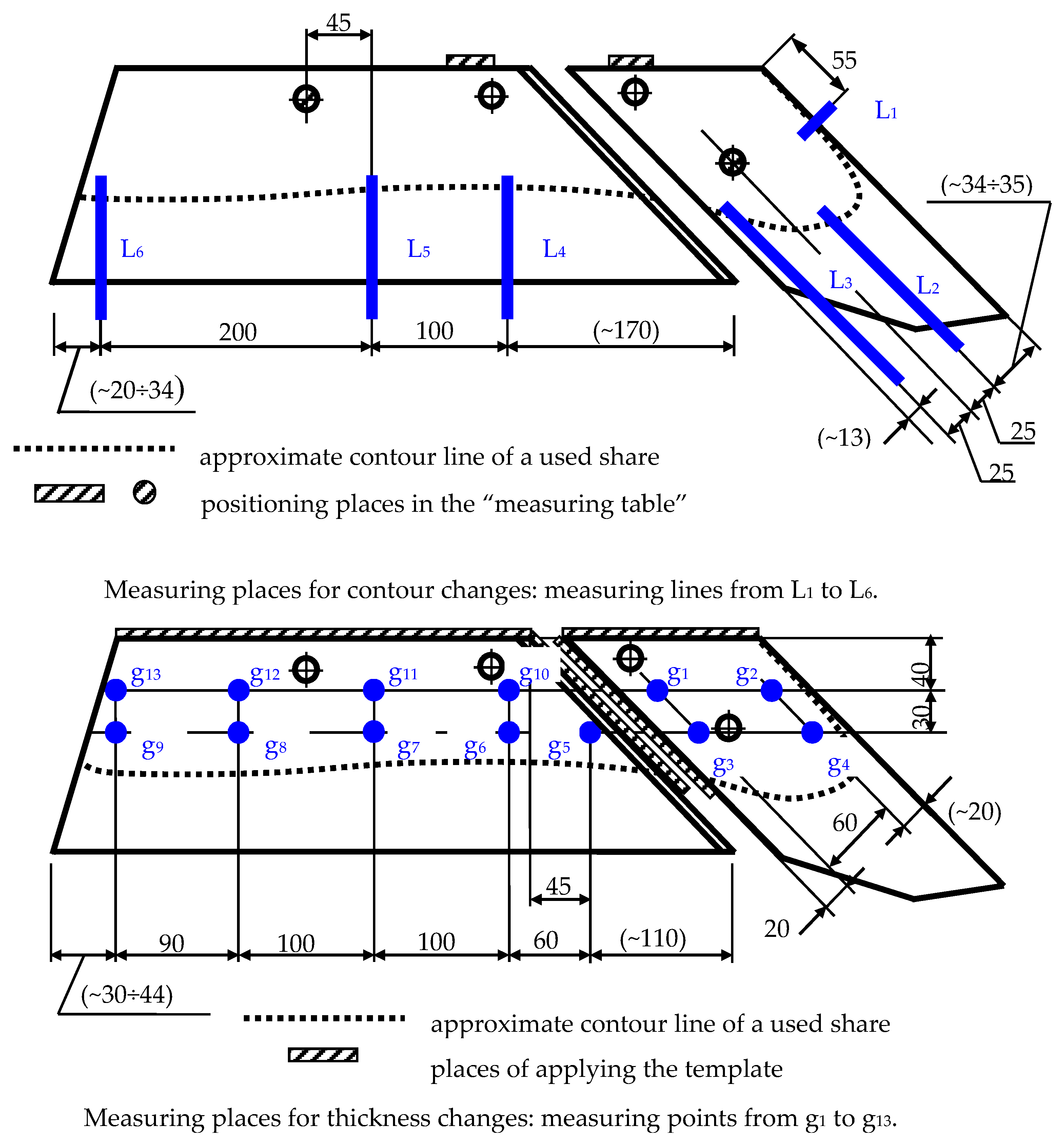
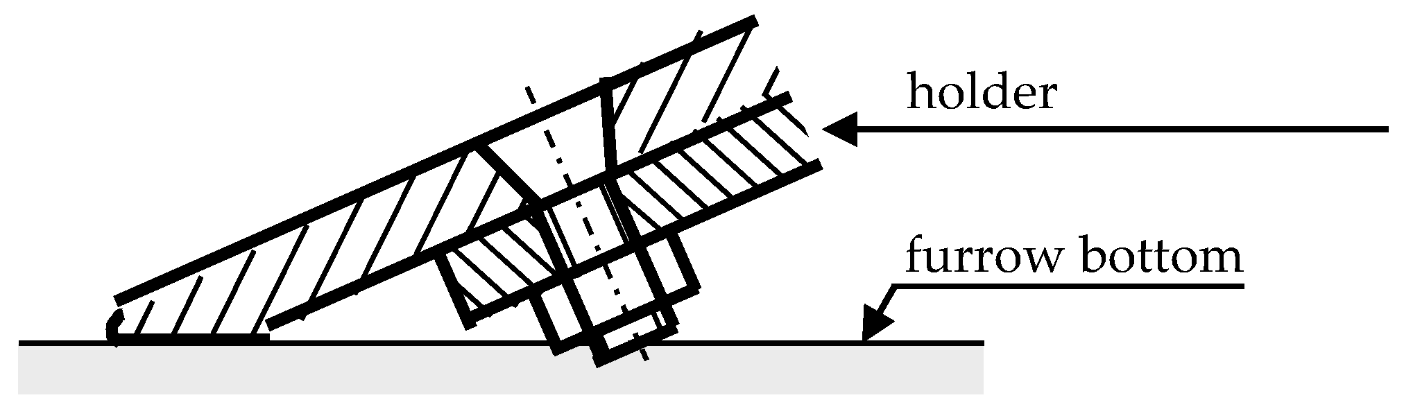
2.3. Evaluation of Wear of the Examined Parts

To evaluate intensity of wear of the examined parts, the following parameters were used: unit mass wear, unit contour change, and unit thickness reduction, determined on the grounds of absolute wear of the parts after cultivation of a determined area. Unit mass wear was determined as the ratio of mass loss of the part to the tilled area attributed to this part (understood as the area tilled to the moment of replacing the part, divided by the number of bodies, i.e., 14 pcs.). The parameters related to the geometry changes of the parts were determined for selected measurement places, as shown in Figure 3. The unit contour change of a part (in mm/ha) was determined as the ratio of the absolute contour change of the part in a given measuring line to the area cultivated by this part. A unit thickness reduction (also in mm/ha) was determined as the ratio of the absolute thickness reduction of the part in a given measuring point to the area cultivated by this part.
Contours of the parts were measured with a slide caliper, and thickness was measured with a micrometer caliper. For contour measurements, a specially prepared “measuring table” was used, making measurements of the distances between bases and edges of the parts possible. Differences between the measurements of the new parts and of the used ones formed the contour change in the given measuring line. For thickness measurements, a template was used, making repeated measurements at the same point possible.
The width of wear bands formed on the flank faces of the parts as a result of the abrasive action of soil from the furrow bottom was also measured. Measurements of this parameter were taken at Lines L2 and L3 at the share-points and Lines L4, L5 and L6 at the trapezoidal parts, see Figure 3. The measurements were made with a slide caliper in the direction perpendicular to the blade lines of the parts.

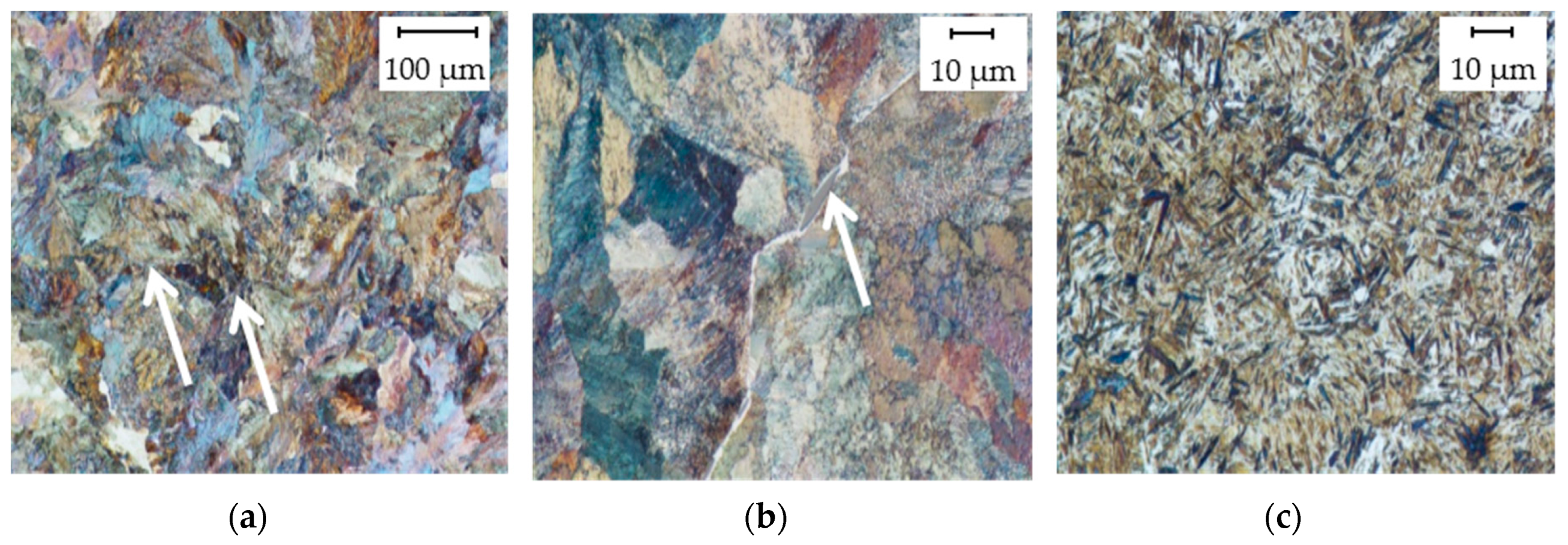
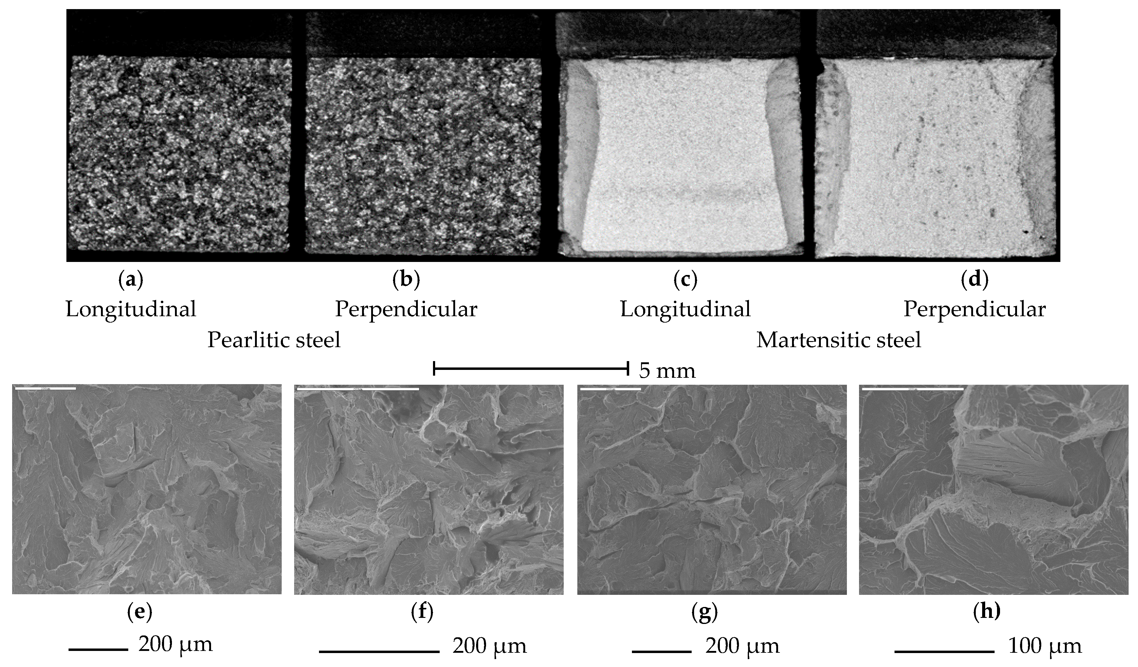
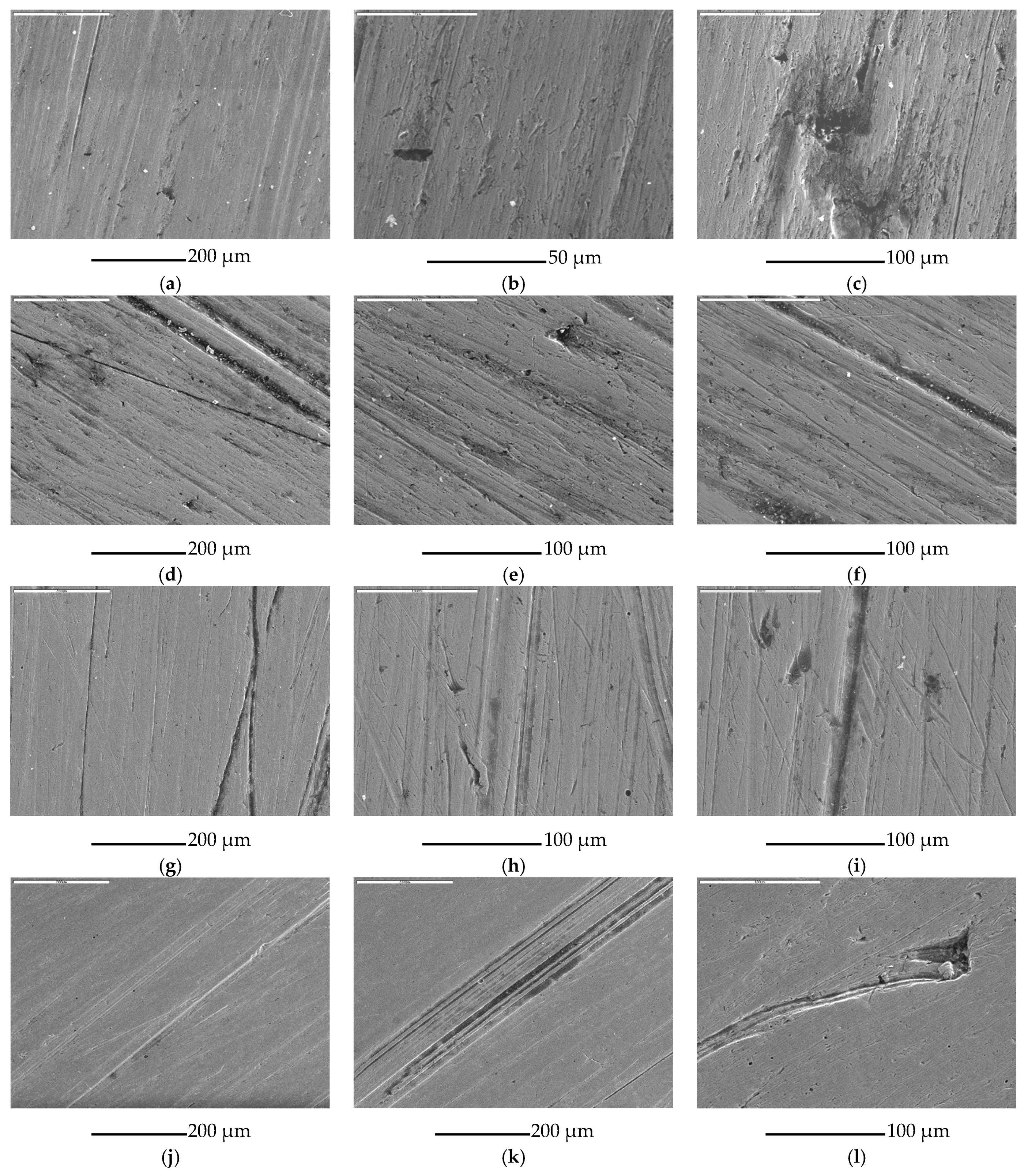
2.4. Evaluation of Surface Condition of the Parts after Operation in Soil

The microgeometry of the rake faces of the parts was measured with a profilographometer, Hommel Tester T1000 (Jenoptic AG, Jena, Germany). The measurements were taken on measuring lengths 4.8 mm (according to EN ISO 4288:2011), repeated four times for each part. The roughness of the surface was described by the arithmetical mean deviation of the roughness profile Ra, the total height of the roughness profile Rt, the maximum valley depth of the roughness profile Rv, and the maximum peak height of the roughness profile Rp. Observation of the rake faces of the examined parts was also carried out using a scanning electron microscope, JEOL JSM-5800LV (Joel Ltd., Tokyo, Japan), coupled with an X-ray microanalyzer, Oxford LINK ISIS-300 (Oxford Instruments, Abingdon, UK).

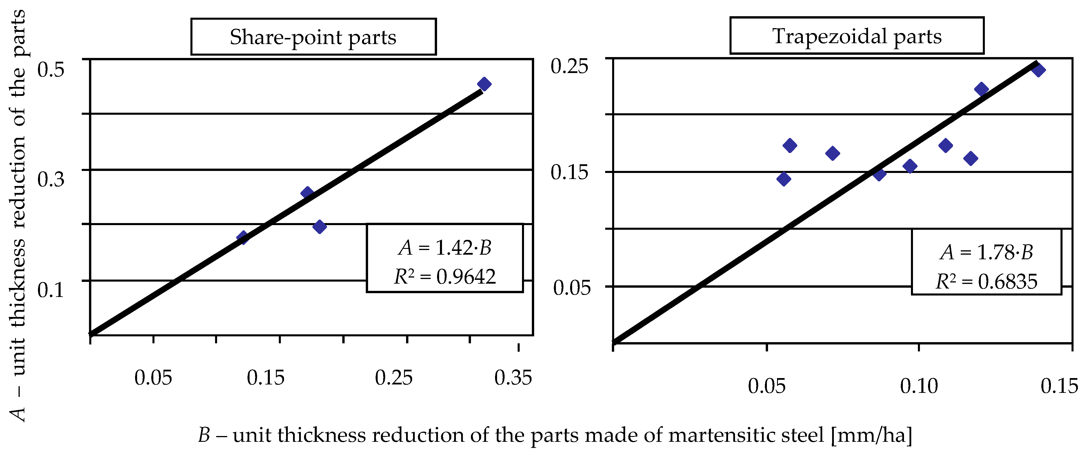
2.5. Statistical Analysis of Measurement Results

Measurement results concerning unit wear, contour change, and thickness reduction were complemented with statistical analysis in order to verify whether the share-points and trapezoidal parts made of comparable steels are characterized by significantly different intensities of wear. Analysis was performed using a Student’s t-test and the method of uncorrelated variables. The accepted significance level α was 0.05. A similar analysis was performed for roughness parameters.

3. Results

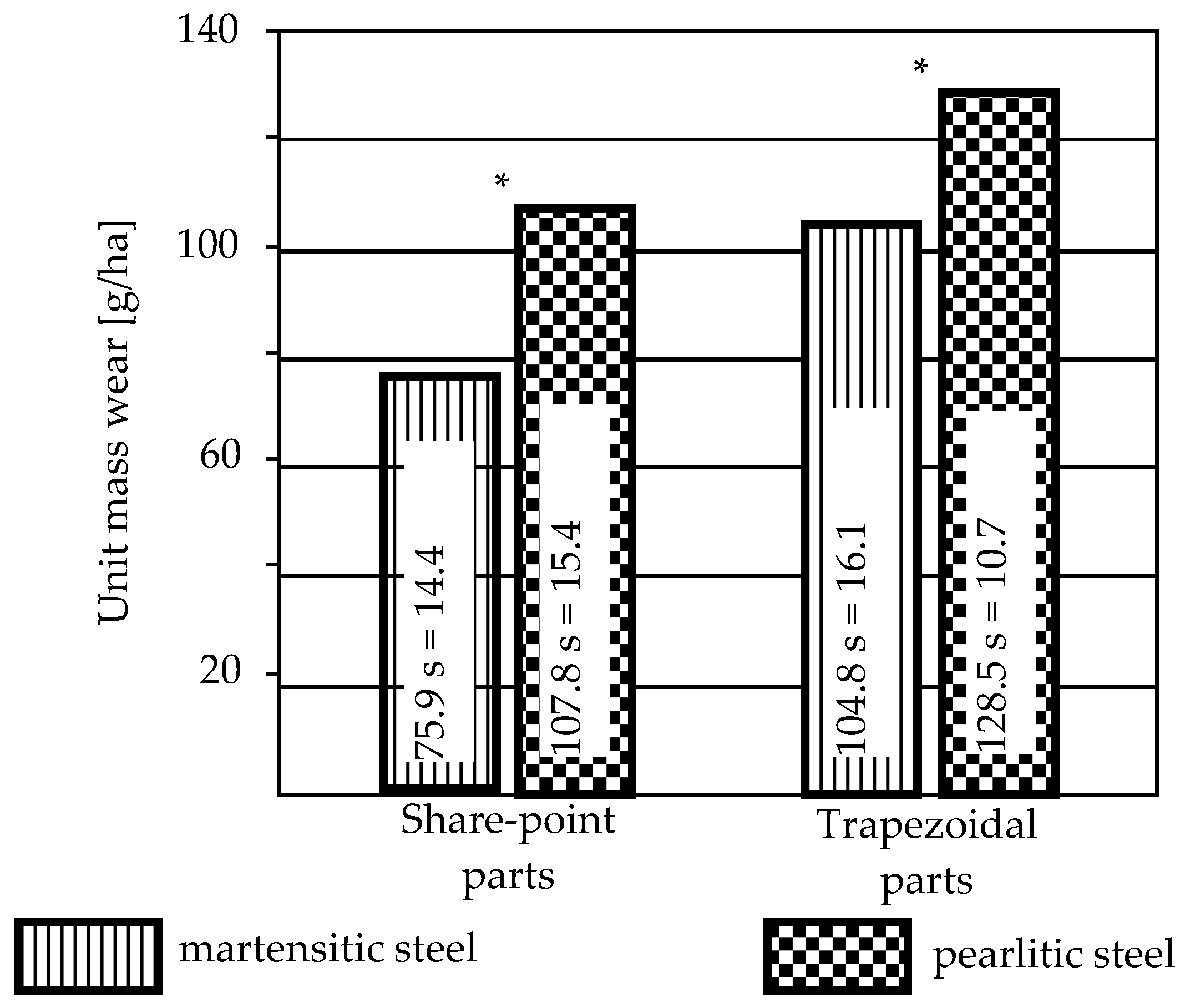
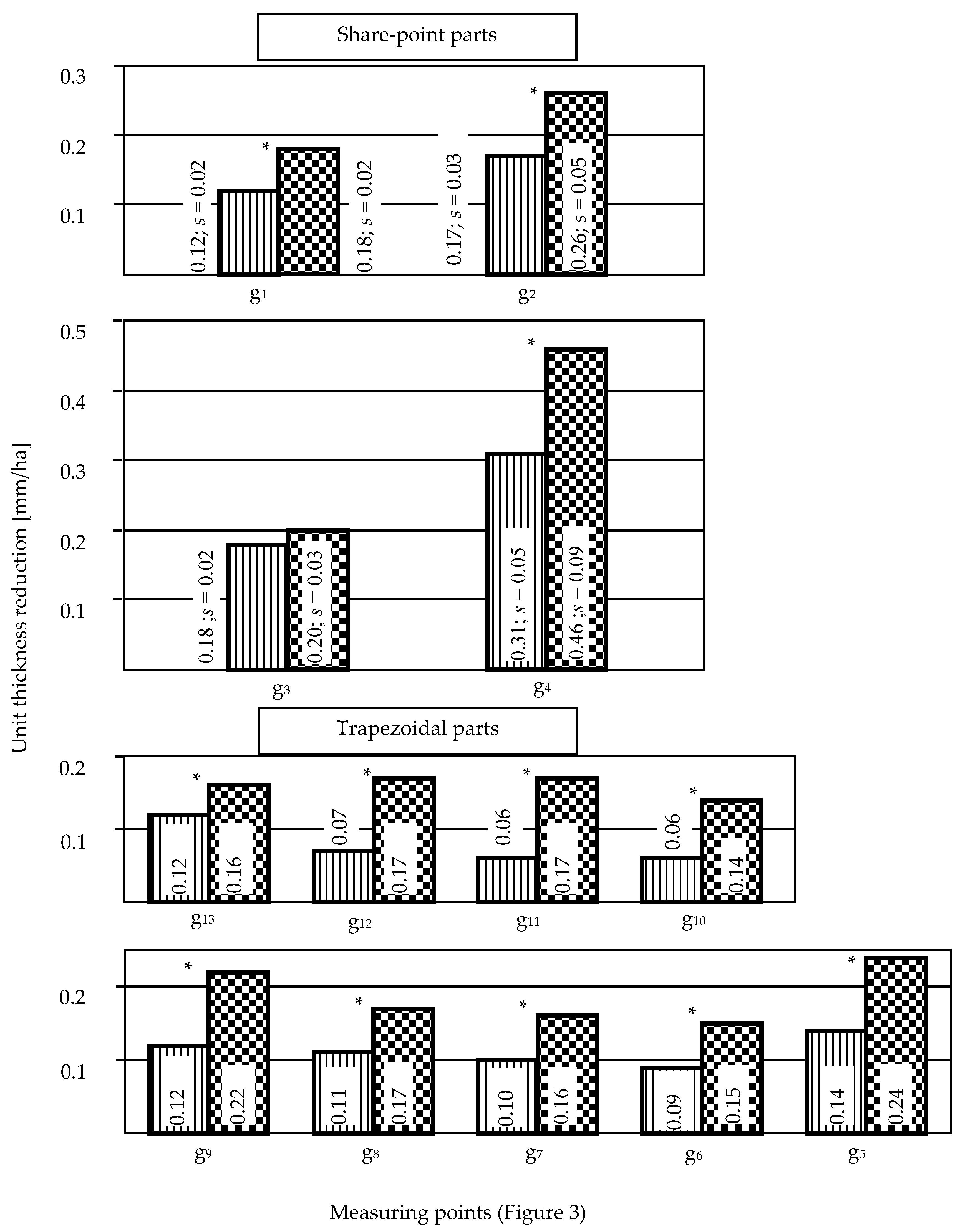
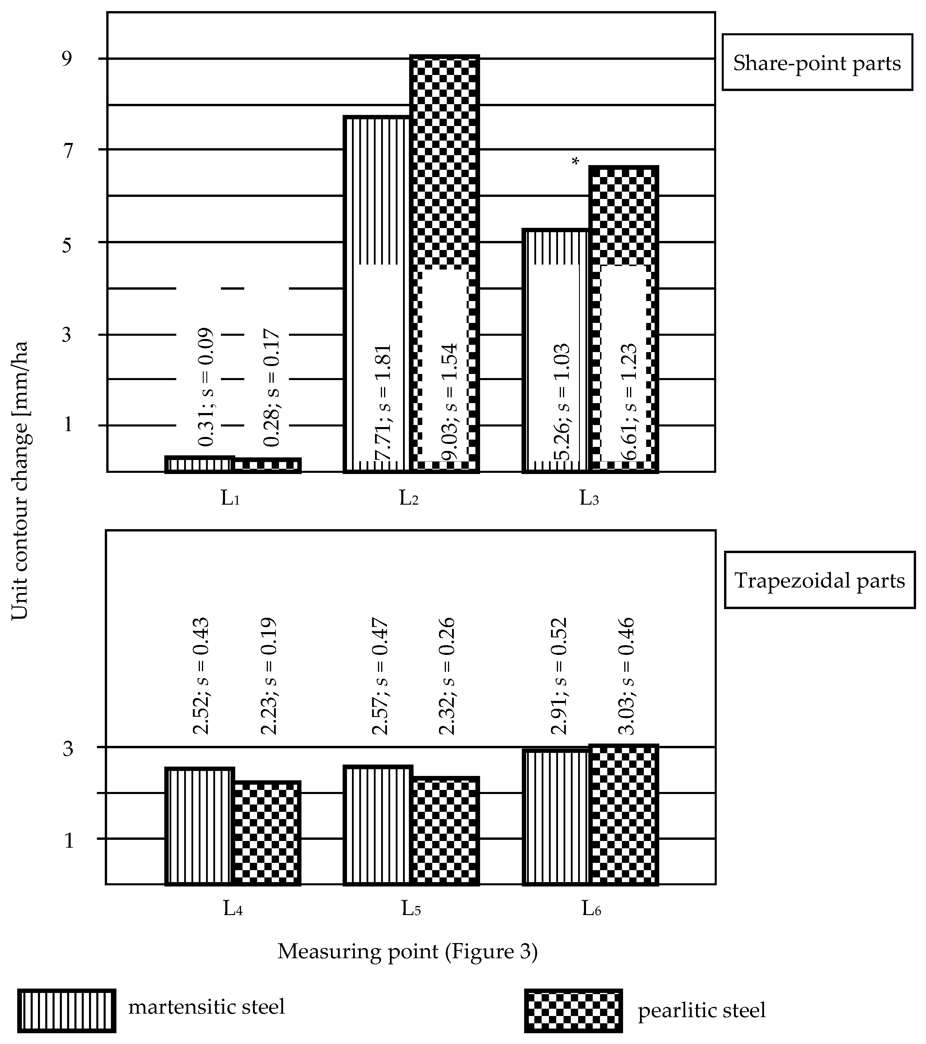
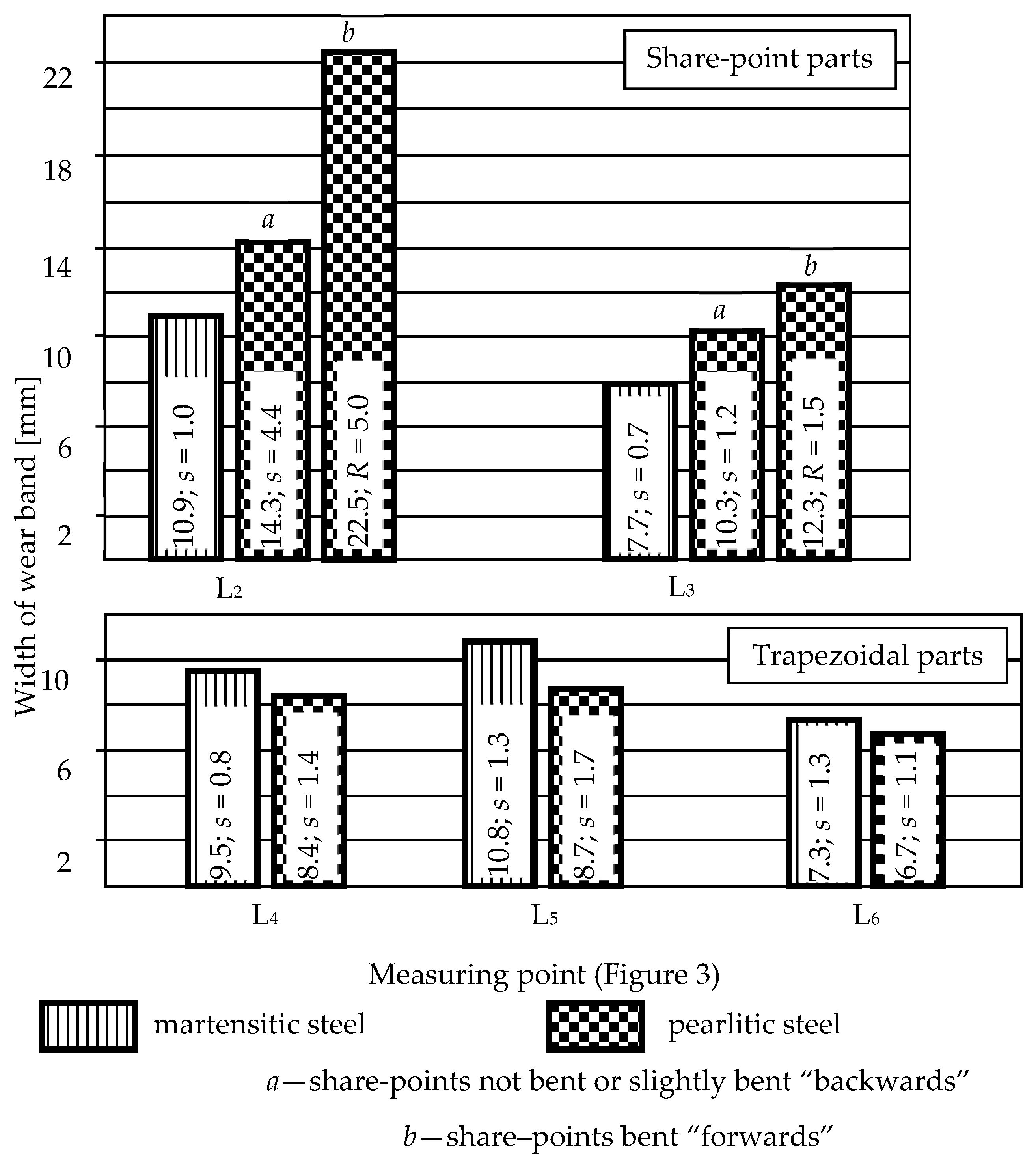
3.1. Wear of the Examined Parts

During tillage, one of the parts was broken: a share-point made of pearlitic steel broke across, in the line running through the lower assembly hole, see Figure 4. After the tests, almost all share-points made of pearlitic steel were somewhat bent, see Figure 5. Looking in the direction of their movement in soil, the share-points were bent “forward” or “backward”. The bends were small and did not exclude the share-points from further operation. It is probable that the “backward” bends were caused by collisions of the shares with stones occurring in soil. The “forward” bends could also result from collisions with stones (at the reaction force directed upwards) or by hitting against the ground on the headlands. A consequence of “forward” bending of the share–points was the necessity to replace them somewhat earlier, because the lower fitting bolts and nuts were uncovered and subjected to abrasive wear. Bending of the trapezoidal parts (Figure 5) was observed on five examined shares but, principally, at the end of their service life, when their thickness was significantly reduced as a result of abrasive wear. Therefore, in the test conditions, bending of the parts made of pearlitic steel was a typical phenomenon.
Considering the above, wear demonstrated by unit mass wear, unit thickness reduction, and unit contour change of the share-points and trapezoidal parts made of pearlitic steel was evaluated in all the parts, both those bent and not bent.
Figure 6 shows values of the unit mass wear of the examined shares. Significant differences between these values for the two used steels (at intensity levels of respectively p = 0.00025 and 0.007 for the share-points and trapezoidal parts; statistically significant differences are marked by asterisks in the figures). In both share-points and trapezoidal parts made of pearlitic steel, more intensive wear was observed compared to the parts made of martensitic steel: ca. 1.42 times more for the share-points and ca. 1.23 times more for the trapezoidal parts.
The trapezoidal parts were characterized by a greater unit mass wear than the share-points: ca. 1.2 times greater for the parts made of pearlitic steel and ca. 1.4 times greater for the parts made of martensitic steel. This can be explained by a ca. 2.4 times larger rake face area in the trapezoidal parts, while it is obvious that material loss occurred also from the sides of the flank faces and field edges of the ploughshares.
The measurement results of the unit thickness reduction of the share-points and trapezoidal parts of the ploughshares are shown in Figure 7. At each measuring point, the values found in the parts made of pearlitic steel were higher than those found in the parts made of martensitic steel: from 0.02 to 0.15 mm/ha for the share-points and from 0.04 to 0.11 mm/ha for the trapezoidal parts. In the share-points, statistically different values were found in three measuring points: g1 (p = 0.001), g2 (p = 0.002), and g4 (p = 0.003), see Figure 3. In the trapezoidal parts, statistically different values of unit thickness reduction were found in all the measuring points (p = 0.0000005–0.0042).
For unit thickness reduction, linear regression analysis was performed in order to find a correlation between the values for the parts made of pearlitic and of martensitic steel. Obvious boundary conditions were accepted for this regression: zero thickness reduction of the parts made of martensitic steel corresponds to zero thickness reduction of the parts made of pearlitic steel. Results of the analysis are shown in Figure 8.
A very strong correlation was found between the unit thickness reduction of the parts made of pearlitic and that made of martensitic steel, indicating a more intensive wear of pearlitic parts: ca. 1.4 times for the share-points and 1.8 times for the trapezoidal parts.
Unit thickness reduction of the parts was greater in the places located in the lower measuring line (measuring points from g3 to g9). The share-points were subjected to the most intensive wear in the area adjacent to the field edge and the nearest to the blade (measuring point g4), which can be related to the highest pressure exerted by the soil on that surface fragment. In the case of the trapezoidal parts, these areas were extreme measuring points located at the lower measuring line (measuring points g5 and g9).
Figure 9 shows the values of the unit contour change of the examined parts. At most of the measuring lines, no statistically significant differences were found for the parts made of pearlitic and of martensitic steel. Such a significant difference occurred only at Line L3, used in the share-points.
For the share-points, unit contour changes were much greater than those for the trapezoidal parts, of course in addition to the wear at Measuring Line L1. A slight tendency for the wear intensity of the trapezoidal parts to increase with increasing distance from the share-points was also observed (increasing parameter values in Lines L4, L5, and L6).
On the grounds of unit contour change of the elements, it is possible to evaluate their durability. It was found that absolute length reduction of the share-points measured at Line L2 (corresponding to limit wear condition) was 96.6 mm, and the width reduction of the trapezoidal parts measured at Line L4 was 63.7 mm. Utilization of the parts beyond the accepted limit wear condition in Lines L2 and L4 (Figure 3) would result in abrasion of the bolts and nuts located under the parts (Figure 10) which, with regard to operation of the plough, should be considered as unacceptable. At durability evaluation, the simplifying assumption was accepted: the intensity of contour changes of the parts at Measuring Lines L2 and L4 does not depend on the cultivated area.
Since no statistically significant differences were found between unit contour changes at Lines L2 and L4, the averaged value of this parameter (determined for the parts made of both martensitic and pearlitic steel) was accepted in the calculations. The so evaluated durability was ca. 11.5 ha for the share-points and 26.8 ha for the trapezoidal parts. Thus, in the testing conditions, the share-points showed a ca. 2.3-fold lower durability compared to that of the trapezoidal parts. It should be noted that the evaluated durability of the share-points made of pearlitic steel concerns the parts that would not be bent or would be bent “backwards”.
Bending of the share-points made of pearlitic steel resulted in various widths of the wear band formed on the flank faces of the parts, see Figure 11 and Figure 12. This parameter is important insofar as, at the wide wear band, difficulties can happen in sinking the plough or in maintaining its set working depth. Bending the share-points “forward” resulted in a ca. 1.6–1.2-fold wider wear band at Measuring Lines L2 and L3, respectively.
The width of the wear bands in the share-points made of pearlitic steel, which were not bent “forward”, was ca. 1.3 times greater than that in the parts made of martensitic steel. However, the width of the wear bands in the trapezoidal parts made of pearlitic steel was ca. 1.1–1.2 times smaller (Figure 11), which can be related to their clearly greater thickness reduction, see Figure 5.
In some share-points made of pearlitic steel, a bending of their tips on a small length and a curling of the blade edges were observed, see Figure 13. These phenomena contributed to more irregular thickness reduction of the parts. Bending the share-points “forward” facilitated the a.m. processes because of the smaller thickness of the parts in their blade areas.

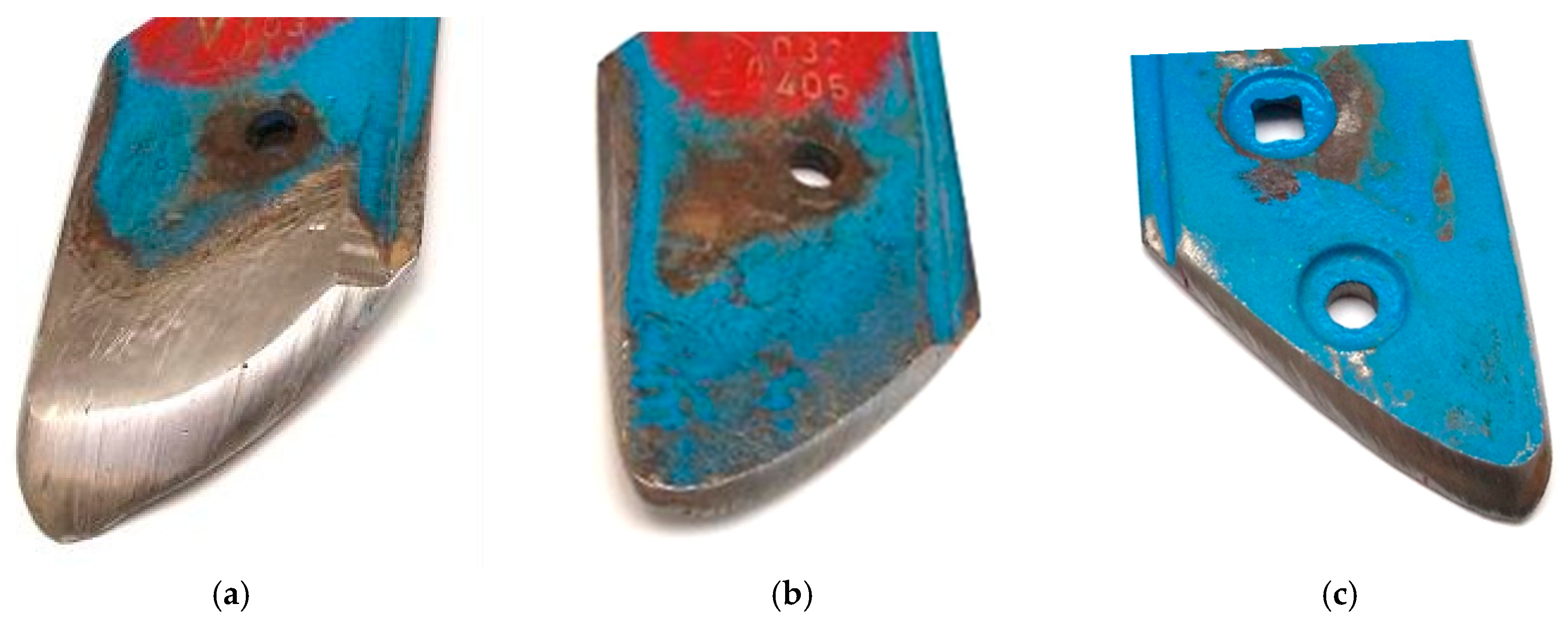
3.2. Condition of the Parts after Operation in Soil

Values of roughness parameters of the rake faces of the examined parts are given in Figure 14, and SEM images of these surfaces are shown in Figure 15.
Statistically significant differences were found in the share-points for the parameters Ra (p = 0.0003), Rt (p = 0.0006), and Rp (p = 0.0001), and in the trapezoidal parts—for the parameters Ra (p = 0.0048), Rt (p = 0.0003), Rv (p = 0.0130), and Rp (p = 0.0002).
The rake faces of the share-points and trapezoidal parts made of pearlitic steel were characterized by a greater roughness than corresponding surfaces of the parts made of martensitic steel. The average roughness Ra was respectively ca. 1.4 and 1.3 times greater for the share-points and trapezoidal parts, the total height of the roughness profile Rt was ca. 1.5 times greater for both share-points and trapezoidal parts, and the maximum peak height of the roughness profile Rp was respectively as much as ca. 1.7 and 1.9 times greater.
Analysis of the wear surface of a share-point made of pearlitic steel shows rough surface topography due to microcutting and microploughing caused by abrasive particles. The scratches and grooves are wide, deep, and randomly orientated, see Figure 15a. There are also visible scratches and scrapes randomly orientated. Moreover, some traces of spalling and pitting, originating in the places where larger areas of material were removed (Figure 15b), were observed at the surfaces. An examination of some pit holes showed the plastic deformation and displacement of material from the impact sites to the crater rims. These phenomena caused formation of grooves with pronounced lips at their rear ends. Abrasive particles could also cause surface fatigue. In these lips, detachment could occur due to these particles. In some pit holes, fragments of embedded abrasive particles are visible (Figure 15c). It can be seen on a surface of a trapezoidal part made of pearlitic steel that the proportion of microploughing increases (Figure 15d–f). The other observation on the surfaces of a share-point (Figure 15g–i) and a trapezoidal part (Figure 15j–l) made of martensitic steel is that scratches and grooves are arranged parallel to the movement direction of abrasive particles along the surface. The grooves are relatively narrow and shallow, but some areas are visible, where scratches and grooves are more concentrated (Figure 15k). Some shallow, randomly orientated scratches can be observed. Grooves formed by moving soil particles and plastically deformed material are visible on the crater rims, see Figure 15i,l.

4. Discussion

A striking result of the research is that values of the unit contour change of the parts made of pearlitic and of martensitic steel are comparable, in the context of the demonstrated differences in mass wear and the intensity of their thickness reduction, see Figure 4 and Figure 5. In most of the measuring places, unit thickness reduction was found to be significantly greater for the ploughshares made of pearlitic steel; significantly higher also were the values of unit mass wear of these parts. However, such a difference did not occur in the case of the parameter of unit contour change. As was already mentioned, the thickness of the parts made of pearlitic steel was greater than the thickness of those made of martensitic steel—by 1 to 3 mm in the share-points and by 0.5 to 2 mm in the trapezoidal parts (Table 3). This probably contributed to the smaller unit contour change of the parts made of pearlitic steel and thus to their longer durability, which is determined by contour change. In consequence, the increased thickness of the parts made of pearlitic steel resulted in a comparable durability of the parts made of pearlitic and martensitic steels. It should be added that pearlitic steel is characterized by a relatively greater resistance to abrasive wear because of the content of a hard cementite phase. This feature certainly affected the obtained results of the tests [27,28].
Some literature data (obtained in laboratory conditions) indicate a more intensive wear of steel working in soil along with its lower hardness, while the intensity of wear depends on the chemical composition of steel and on working conditions [29]. Therefore, the high wear intensity of pearlitic steel with lower hardness in comparison to martensitic steel corresponds—to some extent—with the general regularity in the literature.
During the tests, one share-point part made of pearlitic steel was broken in spite of an >8-fold lower impact strength of pearlitic steel in relation to that of martensitic steel (Table 2), which indicates that these parts can break. However, a significant weak point of both the share-points and the trapezoidal parts made of pearlitic steel is their bending during tillage, which did not occur in the case of the parts made of martensitic steel. This was favored by the low mechanical strength of pearlitic steel (Rm = 911 MPa, Rp0.2 = 494 MPa, respectively, 2- and 3-fold lower than that of martensitic steel, see Table 2). Bending was facilitated by a reduced cross section of the parts and was caused by thickness reduction during operation (Figure 5). The changed geometry of the parts, caused by their bending, could—to some extent—influence the processes of undercutting and crushing the soil, as well as the working resistance of the plough. As was mentioned before, the “forward” bending of the share-points resulted also in their somewhat earlier replacement due to uncovering the fitting bolts and to the creation of a wide wear band. It seems that a possible way of strengthening the parts could be further increasing their thickness, but it is uncertain whether that would be an effective solution with so clearly a lower strength of pearlitic steel. At the same time, this way is restricted by requirements of the plough design. In addition, a wide wear band is created on the flank faces of the thicker parts, which can result in a longer distance of the plough sinking on the headlands and in periodic reduction of the set tillage depth.
Larger roughness found on the rake faces of the parts made of pearlitic steel (Figure 14) can be related to lower mechanical properties of this steel and, especially, with ca. 1.8 times lower hardness than that of martensitic steel, see Table 2. Higher roughness values indicate a more intensive course of wear of pearlitic steel. The maximum peak height of the roughness profile values (Rp) on the share-points and trapezoidal parts made of pearlitic steel were respectively ca. 1.7 and 1.9 times greater than those for the parts made of martensitic steel. Thus, in the course of the wear process of pearlitic steel, the material was subjected to more intensive plastic deformation, characteristic of ridging, which was confirmed by SEM observations and former literature data [30,31,32,33].
It is also interesting that values of the parameters Ra, Rt, Rv, and Rp determined for the share-points and trapezoidal parts made of the same material slightly differ from each other, see Figure 14. Generally, the values found on the trapezoidal parts were a bit lower, but the differences did not exceed 14% of the parameter value. In this case, the performed roughness measurements did not show any statistically significant differences. This advocates a similar interaction of elementary wear processes occurring on rake faces of the share-points and trapezoidal parts. Therefore, considering a more intensive unit thickness reduction of the share-points in comparison to that of trapezoidal parts, it can be assumed that the more intensive wear of the share-points resulted from a greater intensity of the occurring wear processes.
It should be added that, for a user of agricultural equipment, the purchase cost of the applied replacement parts is an important factor in addition to their durability. The railway rails withdrawn from use are a cheap raw material that can be subjected to material recycling. One of the forms of such action is manufacturing ploughshares from recycled rails. In this case, the low price of raw material significantly influences the prices of ploughshares that are in Poland—ca. 2 times cheaper than those produced by renowned manufacturers of agricultural equipment.

5. Conclusions

(1) In the tillage tests carried out, the intensity of thickness reduction of ploughshares was greater for the parts made of pearlitic steel than that for the parts made of martensitic steel: ca. 1.4 times greater for share-points and ca. 1.8 times greater for trapezoidal parts. Unit mass wear was also more intensive for the parts made of pearlitic steel: 1.4 times greater for share-points and 1.2 times greater for trapezoidal parts. This indicates that pearlitic steel, compared to martensitic steel, has a lower resistance to wear in soil.
(2) After operation in soil, the rake faces of the parts made of pearlitic steel showed greater roughness than the parts made of martensitic steel, which can be attributed to pearlitic steel’s lower hardness. This indicates a more intensive run of wear phenomena in pearlitic steel. The maximum peak height of the roughness profile values (Rp) were as much as respectively 1.7 and 1.9 times greater for the share-points and trapezoidal parts made of pearlitic steel in comparison to those made of martensitic steel. Therefore, in the parts made of pearlitic steel, plastic deformation of the surface layer material destroyed by soil particles was significantly greater.
(3) In spite of the 8-fold lower impact strength of pearlitic steel compared to that of martensitic steel, only one part was broken (the plough with overload protection of the bodies was used). However, most of the share-points and trapezoidal parts made of pearlitic steel were somewhat bent, which was favored by the successive reduction of the cross-section area of the parts as a result of thickness reduction. Nevertheless, in this case, the parts need not be replaced immediately. Earlier replacement was necessary in the case of “forward” bending of a share-point because the fitting bolts became uncovered. Wide wear bands were created on the flank faces of the so shaped share-points. One compensation for the described disadvantage of the parts made of pearlitic steel is their lower price.
(4) With pearlitic steel’s greater susceptibility to wear in soil, the parts made of this steel were characterized by comparable values of unit contour change in relation to the parts made of martensitic steel. This fact was probably influenced by the greater thickness of the parts made of pearlitic steel (increased by 1 to 3 mm in share-points and by 0.5 to 2 mm in trapezoidal parts). Therefore, it is probable that, if the pearlitic share-points were not subjected to bending, their durability would be comparable to that of the parts made of martensitic steel.
(5) The bending of the ploughshares made of pearlitic steel is their definite disadvantage, since it influences to some extent interaction between the parts and soil. The bending strength of the parts could be increased by the parts’ increased thickness, although this action is restricted by specific design solutions of the plough. It should be also emphasized that wide wear bands are formed on thicker parts, which can result in a lower agricultural quality of tillage.

Author Contributions

Tomasz Stawicki contributed reagents/materials/analysis tools, conceived and designed the experiments, analysed data, wrote the paper; Beata Białobrzeska contributed reagents/materials/analysis tools, conceived and designed the experiments, analysed data, wrote the paper; Piotr Kostencki contributed reagents/materials/analysis tools, conceived and designed the experiments, analysed data, wrote the paper.

Conflicts of Interest

The authors declare no conflict of interest.

References

  1. Owsiak, Z.; Zużycie lemieszy pługów Cz., I. Charakter zużycia i stan graniczny lemieszy pługów. Rocz. Nauk. Rol. 1988, 77, 69–75. [Google Scholar]
  2. Kushwaha, R.L.; Shi, J. Investigation of wear of agricultural tillage tools. Lubr. Eng. 1989, 47, 219–222. [Google Scholar]
  3. Müller, M.; Hrabě, P. Overlay materials used for increasing lifetime of machine parts working under conditions of intensive abrasion. Res. Agric. Eng. 2013, 59, 16–22. [Google Scholar]
  4. Hamblin, M.G.; Stachowiak, G.W. Description of abrasive particle shape and its relation to two-body abrasive wear. Tribol. Trans. 1996, 39, 803–810. [Google Scholar] [CrossRef]
  5. Natsis, A.; Papadakis, G.; Pitsilis, J. The Influence of soil type, soil water and share sharpness of a mouldboard plough on energy consumption, rate of work and tillage quality. J. Agric. Eng. Res. 1999, 72, 171–176. [Google Scholar] [CrossRef]
  6. Natsis, A.; Petropoulos, G.; Pandazaras, C. Influence of local soil conditions on mouldboard ploughshare abrasive wear. Tribol. Int. 2008, 41, 151–157. [Google Scholar] [CrossRef]
  7. Napiórkowski, J. Zużyciowe oddziaływanie gleby na elementy robocze narzędzi rolniczych. Inżynieria Rol. 2005, 9, 3–171. [Google Scholar]
  8. Yu, H.J.; Bhole, S.D. Development of prototype abrasive wear tester for tillage tool material. Tribol. Int. 1990, 23, 309–316. [Google Scholar] [CrossRef]
  9. Miller, E.A. Wear in tillage tools. In Wear Control Handbook; Peterson, M. D., Winer, W.O., Eds.; ASME: New York, NY, USA, 1984; pp. 987–998. [Google Scholar]
  10. Kostencki, P. Geometria zużycia lemieszy płużnych użytkowanych w glebach piaszczystych. Probl. Inżynierii Rol. 2007, 3, 49–64. [Google Scholar]
  11. Kostencki, P.; Nowowiejski, R. Wytrzymałość ścierna wybranych lemieszy płużnych podczas uprawy pyłu zwykłego o dwóch stanach nawilgocenia. Tribology 2006, 2, 123–142. [Google Scholar]
  12. Napiórkowski, J. Wpływ odczynu gleby na intensywność zużycia elementów roboczych. Tribology 1997, 793–801. [Google Scholar]
  13. Stabryła, J. Research on the degradation process of agricultural tools in soil. Probl. Eksploat. 2007, 4, 223–232. [Google Scholar]
  14. Napiórkowski, J.; Michalski, R. Zwiększanie trwałości elementów roboczych w glebie metodami napawania. In Proceedings of the III Ogólnopolska Konferencja Naukowo-Techniczna, Jachranka, Poland, 24–26 May 1995; pp. II-27–II-37. [Google Scholar]
  15. Bayhan, Y. Reduction of wear via hardfacing of chisel ploughshare. Tribol. Int. 2006, 39, 570–574. [Google Scholar] [CrossRef]
  16. Hrabě, P.; Müller, M. Research of overlays influence on ploughshare lifetime. Res. Agric. Eng. 2013, 59, 147–152. [Google Scholar]
  17. Novák, P.; Müller, M.; Hrabě, P. Research of a material and structural solution in the area of conventional soil processing. Agron. Res. 2014, 12, 143–150. [Google Scholar]
  18. Horvat, Z.; Filipovic, D.; Kosutic, S.; Emert, R. Reduction of mouldboard plough share wear by a combination technique of hardfacing. Tribol. Int. 2008, 41, 778–782. [Google Scholar] [CrossRef]
  19. Białobrzeska, B.; Kostencki, P. Abrasive wear characteristics of selected low-alloy boron steels as measured in both field experiments and laboratory tests. Wear 2015, 328, 149–159. [Google Scholar] [CrossRef]
  20. Er, U.; Par, B. Wear of plowshare components in SAE 950C steel surface hardened by powder boriding. Wear 2006, 261, 251–255. [Google Scholar] [CrossRef]
  21. Tian, Z.; Sun, W.; Shang, M.; Jiang, X.; Han, W.; Li, L. Application of boronizing technology on ploughshares and study on the abrasive wear characteristics under low stress of boronized layer. In Proceedings of the International Symposium on Agricultural Engineering (89-ISAE), Beijing, China, 12–15 September 1989; International Academic Publishers: Beijing, China, 1989; pp. 248–249. [Google Scholar]
  22. Foley, A.G.; Lawton, P.J.; Barker, A.W.; McLees, V.A. The use of alumina ceramic to reduce wear of soil-engaging components. J. Agric. Eng. Res. 1984, 30, 37–46. [Google Scholar] [CrossRef]
  23. Napiórkowski, J.; Ligier, K. Wear testing of α-Al2O3 oxide ceramic in a diverse abrasive soil mass. Tribology 2014, 1, 63–74. [Google Scholar]
  24. Napiórkowski, J.; Ligier, K.; Pękalski, G. Tribological properties of cemented carbides in abrasive soil mass). Tribology 2014, 2, 123–134. [Google Scholar]
  25. Müller, M.; Chotěborský, R.; Valášek, P.; Hloch, S. Unusual possibility of wear resistance increase research in the sphere of soil cultivation. Teh. Vjes. 2013, 20, 641–646. [Google Scholar]
  26. Kostencki, P.; Stawicki, T.; Białobrzeska, B. Durability and wear geometry of subsoiler shanks provided with sintered carbide plates. Tribol. Int. 2016, 104, 19–35. [Google Scholar] [CrossRef]
  27. Perez-Unzueta, A.J.; Beynon, J.H. Microstructure and wear resistance of pearlitic rail steels. Wear 1993, 162, 173–182. [Google Scholar] [CrossRef]
  28. Viafara, C.C.; Castro, M.I.; Velez, J.M.; Toro, A. Unlubricated sliding wear of pearlitic and bainitic steels. Wear 2005, 259, 405–411. [Google Scholar] [CrossRef]
  29. Severnev, M.M. Wear of Agricultural Machine Parts; USDA/Amerind Publishing CO. Pyt. Ltd.: New Delhi, India; Washington, DC, USA, 1984.
  30. Kazemipour, M.; Shokrollahi, H.; Sharafi, S. The influence of the matrix microstructure on abrasive wear resistance of heat-treated Fe–32Cr–4.5C wt % hardfacing alloy. Tribol. Lett. 2010, 39, 181–192. [Google Scholar] [CrossRef]
  31. Hokkirigawa, K.; Kato, K. An experimental and theoretical investigation of ploughing, cutting and wedge formation during abrasive wear. Tribol. Int. 1988, 21, 51–57. [Google Scholar] [CrossRef]
  32. Sapate, S.G.; Selokar, A.; Garg, N. Experimental investigation of hardfaced martensitic steel under slurry abrasion conditions. Mater. Des. 2010, 31, 4001–4006. [Google Scholar] [CrossRef]
  33. Turenne, S.; Lavallee, F.; Masounave, J. Matrix microstructure effect on the abrasion wear resistance of high–chromium white cast iron. J. Mater. Sci. 1989, 24, 3021–3028. [Google Scholar] [CrossRef]
Figure 1. Microstructures of ploughshare materials: (a) pearlitic steel with ferrite on grain boundaries (indicated by arrows); (b) pearlitic steel with ferrite on grain boundaries, in some places non-homogeneous, with visible inclusions, probably sulfides (indicated by an arrow); (c) martensitic steel, the structure of fine-acicular tempered martensite.
Metals 07 00139 g001
Figure 2. Fracture surfaces of pearlitic and martensitic steels after the impact test. (ad) macroscopic images of fracture surfaces after the impact test; Pearlitic steel: (e,f) cleavage fracture with characteristic “river” profile (longitudinal), (g,h) cleavage fracture with characteristic “river” and “fan” profiles (perpendicular); Martensitic steel: (i) plastic side zone (longitudinal), (j) quasi-cleavage fracture with developed topography (longitudinal), (k) cavities after non-metallic inclusions (longitudinal), (l) cavities after non-metallic inclusions (perpendicular).
Metals 07 00139 g002aMetals 07 00139 g002b
Figure 3. Measuring places for geometry changes of the examined shares, all results are in mm.
Metals 07 00139 g003
Figure 4. Broken share-point part made of pearlitic steel.
Metals 07 00139 g004
Figure 5. Bending of share-point and trapezoidal parts made of pearlitic steel: (a) a share-point part bent “backward”; (b,c) longitudinal bend of a trapezoidal part; (d) transverse bend of a trapezoidal part. The presented parts are relatively strongly bent.
Metals 07 00139 g005
Figure 6. Unit mass wear of share-points and trapezoidal parts of the examined ploughshares (s—standard deviation, *—statistically significant differences).
Metals 07 00139 g006
Figure 7. Unit thickness reduction of share-point parts and trapezoidal parts of the examined ploughshares-standard deviation for trapezoidal parts: s = 0.01–0.03 mm/ha. (*—statistically significant differences).
Metals 07 00139 g007
Figure 8. Relation between unit thickness reduction of the parts made of pearlitic and of martensitic steel (R2—coefficient of determination).
Metals 07 00139 g008
Figure 9. Unit contour change of share-points and trapezoidal parts of the examined ploughshares (s—standard deviation, *—statistically significant differences).
Metals 07 00139 g009
Figure 10. Limit wear condition of ploughshares resulting from the contour change.
Metals 07 00139 g010
Figure 11. Width of the wear band created on the flank faces of the share-points and trapezoidal parts after the tillage test: 8.43–12.29 and 20.93 ha/body, respectively. s—standard deviation, R—range. No significance test was performed for this parameter.
Metals 07 00139 g011
Figure 12. Wear band on the flank faces of the share-points: (a) pearlitic steel, “forward” bent; (b) pearlitic steel, slightly “backward” bent; (c) martensitic steel.
Metals 07 00139 g012
Figure 13. Exemplary bending of the tip and curling of the blade edge in the share-point made of pearlitic steel.
Metals 07 00139 g013
Figure 14. The roughness of the rake faces of the examined ploughshares: Ra—arithmetical mean deviation of the roughness profile, Rt—total height of the roughness profile, Rv—maximum valley depth of the roughness profile, Rp—maximum peak height of the roughness profile (s—standard deviation, *—statistically significant differences).
Metals 07 00139 g014
Figure 15. Rake faces of the examined parts (SEM). Rake face surface of a share-point made of pearlitic steel: (a) scratches and grooves, (b) pit hole, (c) fragments of embedded abrasive particle; Surface of a trapezoidal part made of pearlitic steel: (d) scratches and grooves, (e) fragments of embedded abrasive particle, (f) groove and plastic deformation; Surface of a share-point made of martensitic steel: (g) scratches and grooves, (h) holes formed during a particle impact, (i) groove and holes formed during a particle impact and embedded abrasive particle; Surface of a trapezoidal part made of martensitic steel: (j) scratches and grooves, (k) grooves, (l) groove formed during a particle impact and embedded abrasive particle.
Metals 07 00139 g015
Table 1. The chemical composition of steels used for ploughshares.
ElementConcentration [wt %]
Pearlitic SteelMartensitic Steel
C0.8090.362
Mn0.8841.270
Si0.2140.230
P0.0220.013
S0.0250.006
Cr0.0610.256
Ni0.0580.084
Mo0.0050.019
V0.0010.000
Cu0.0740.138
Al0.0160.031
Ti0.0020.043
Co0.0190.005
As0.0320.000
B0.00040.0023
Pb0.0020.002
Zr0.0080.004
FeRem.Rem.
Table 2. Mechanical properties of the examined materials.
ParameterMaterial
Pearlitic SteelMartensitic Steel
Hardness [HBW]share-point258.0s = 4.7476.0s = 3.5
trapezoidal part265.4s = 2.8472.2s = 1.8
Impact strength [J/cm2]—relation to plastic working directionlongitudinal4s = 0.337s = 0.3
perpendicular3s = 0.325s = 2.6
Tensile strength Rm [MPa]911s = 991833s = 40
Proof stress Rp0.2 [MPa]494s = 701482s = 35
Ultimate elongation A [%]10s = 1.010s = 0.4
s—standard deviation.
Table 3. Dimensions and masses of the examined ploughshares.
Designations
Metals 07 00139 i001
Ploughshare MaterialDimensions [mm]
Share-PointsTrapezoidal PartsW10
W1W2W3W4/aW5/aW6W7W8W9/a
Martensitic steel973359–15 1)28/327/34961491142/4650
Pearlitic steel9933812–16 1)28/525/548014612–1330/5643
Mass [g]
Martensitic steel1846.6s = 22.04588.3s = 19.2
Pearlitic steel2157.4s = 38.04907.4s = 52.3
a—blade thickness; 1) Maximum thickness occurred at the field edge, close to half of its length; s—standard deviation.
Table 4. Operating conditions of ploughshares.
QuantityDetermined Average ValueSoil Layer
Percentages of soil grades in tillable layer of the cultivated area [%]sandy loams and loams63Tillable layer
loamy sands34
sands3
Percentage of skeleton particles (fraction 2 to 30 mm) [%]2.4; s = 1.0
Stoninessfine stones (3–14 cm):
15 t/ha; s = 8 (168,000 pcs./ha; s = 80,000)
large stones: 28 pcs./ha; s = 31
Reaction [pHKCL]6.07–6.33
Humus content [%]1.78; s = 0.25
Actual humidity [wt %]13.5; s = 1.8 13.1; s = 1.30–15 cm 15–30 cm
Volumetric density [g/cm3]1.45; s = 0.06 1.49; s = 0.130–15 cm 15–30 cm
Consistency [kPa]789; s = 166 1866; s = 4960–15 cm 15–30 cm
Shearing stresses [kPa]47.0; s = 10.3 65.2; s = 19.20–15 cm 15–30 cm
Working width [m]0.45; s = 0.04
Working depth [cm]20.5; s = 3.5
Speed [m/s]2.78; s = 0.25
Besides percentages of soil grades, average values for individual quantities were calculated on the grounds of the data obtained in six individual days of testing; s—standard deviation.
Table 5. Exemplary percentages of granulometric fractions in the cultivated soil.
Sample No.Percentages of A Granulometric Fraction [%]Granulometric Group
SandSiltClay
very Coarse 1.0 < d ≤ 2.0Coarse 0.5 < d ≤ 1.0Medium 0.25 < d ≤ 0.5Fine 0.10 < d ≤ 0.25very Fine 0.05 < d ≤ 0.10Coarse 0.02 < d ≤ 0.05Fine 0.002 < d ≤ 0.02d ≤ 0.002
11.75.811.734.220.110.810.84.9FSL
21.86.512.330.919.012.810.85.9FSL
31.76.310.922.423.410.814.79.8SL
41.95.411.134.419.78.812.85.9FSL
51.13.66.915.222.724.815.89.9L
61.44.59.336.423.86.911.85.9FSL
d—size of soil grain [mm]; FSL—fine sandy loam; SL—sandy loam; L—loam.

