Abstract
High-frequency impacting and rolling was applied on AZ31B magnesium alloy to obtain a gradient nano-structured surface. Surface characteristics were experimentally investigated, and the nanocrystallization mechanism is discussed in detail. Results showed that the gradient nano-structure with the characteristics of work hardening, compressive residual stress and a smooth surface was induced on the treated surface. Grains on the top surface were generally refined to around 20 nm. Twins, dislocations and dynamic recrystallization dominated the grain refinement process. Fatigue strength of the treated specimens corresponding to 107 cycles was increased by 28.6% compared to that of the as-received specimens. The work hardened layer induced by high-frequency impacting and rolling is the major reason to improve fatigue life.
1. Introduction
Magnesium alloys are extensively used in aerospace, electronics, military and other industry fields for weight reduction effectiveness [1,2,3]. However, the application of magnesium alloy has been limited by its low absolute strength and poor fatigue performance. The above problems will hopefully be resolved with the rapid development of surface strengthening technology [4,5,6]. Surface nanocrystallization induced by severe plastic deformation (SPD) has been drawing more and more attention in recent years [7,8,9]. Current surface strengthening methods generally include shot peening (SP), ultrasonic shot peening (USP), surface mechanical attrition treatment (SMAT), cryogenic burnishing, etc. The past studies showed that SPD on the material surface can effectively improve the fatigue performance of structural components. For example, Gao [10,11] investigated the influence of SP on the tension-tension fatigue properties of two kinds of high strength Ti alloys and found that fatigue strength for 1 × 10⁷ cycles can be increased by 27%–29%. Arakawa et al. [12] studied the effect of USP on the fatigue characteristics of high strength structural materials of hydroelectric facilities, and the results showed that the fatigue limit of the treated material was approximately increased by 60%. For the high strength materials, the higher compressive residual stress can be formed and maintained after surface strengthening treatment, and the fatigue properties can be better improved [13,14]. As to low strength materials (magnesium or aluminum alloy), the lower compressive residual stress induced by surface strengthening treatment is easily relaxed at the moment a random or occasional high load appears, which will result in a limited improvement of fatigue properties. Therefore, it is unusual to improve the fatigue properties of low strength materials by surface strengthening treatment. For example, Lu et al. only studied the surface nanocrystallization mechanism of magnesium alloy based on SMAT technology [6]. Tsai et al. [15] also only analyzed the relationship between the microstructure and properties for different processing parameters of SMAT. Jordan Moering et al. studied the microstructural and textural development along the depth under the effect of SMAT by electron backscattered diffraction (EBSD) [16]. Pu et al. [17] proposed a new method called cryogenic burnishing. For the Mg-Al-Zn alloy treated by cryogenic burnishing, a large increase in microhardness from 0.86–1.35 GPa was obtained, and grains were refined from 12 μm down to 263 nm. However, the fatigue performance of Mg-Al-Zn alloy based on cryogenic burnishing treatment still has not been studied.
Generally, SPD methods are easy to result in the increase of surface roughness, cause a large stress concentration and deteriorate the improvement of fatigue life. High-frequency impacting and rolling (HFIR) as a kind of newly-developed surface nanocrystallization technology has been attracting more and more attention in recent years. HFIR treatment can generate a gradient nano-structured surface, as well as significantly reduce surface roughness. In this study, HFIR was used to treat AZ31B magnesium alloy to obtain a gradient nano-structured surface. Then, the nanocrystallization mechanism was discussed in detail, and the effect of surface nanocrystallization on the fatigue fracture mechanism of magnesium alloy was analyzed.
2. Material and Experiments
2.1. Material
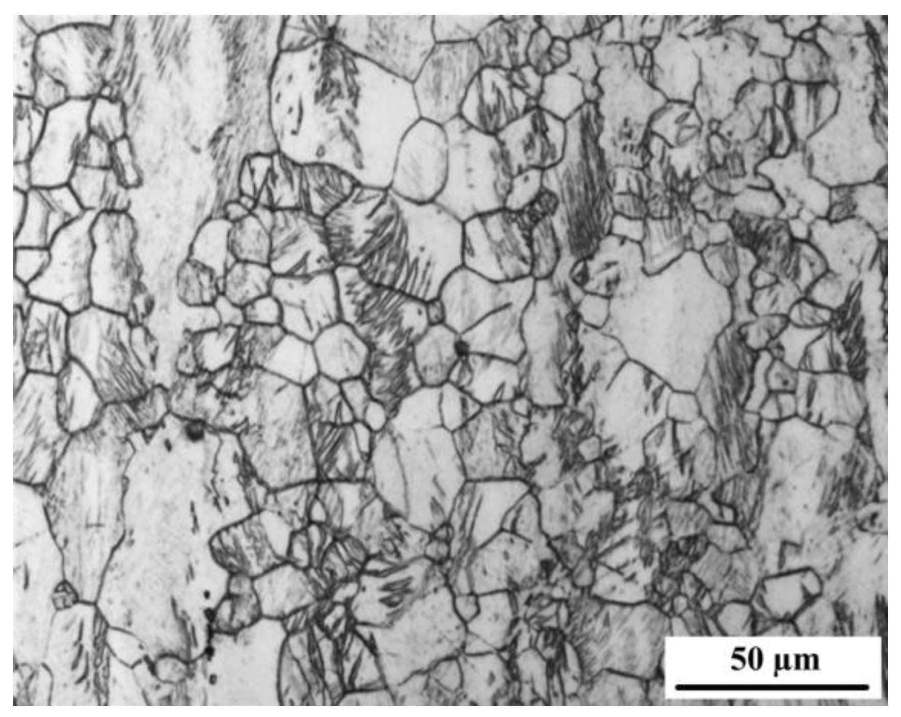
The material used was AZ31B magnesium alloy, and the microstructure is shown in Figure 1, which consists of unevenly-equiaxed grains and a small amount of second β-Mg17Al12 phase precipitating along grain boundaries. The yield strength and the ultimate tensile strength through experimental measurement are about 174 MPa and 246 MPa, respectively.

Figure 1.
The microstructure of AZ31B magnesium alloy.
2.2. Fatigue Specimen and HFIR Treatment
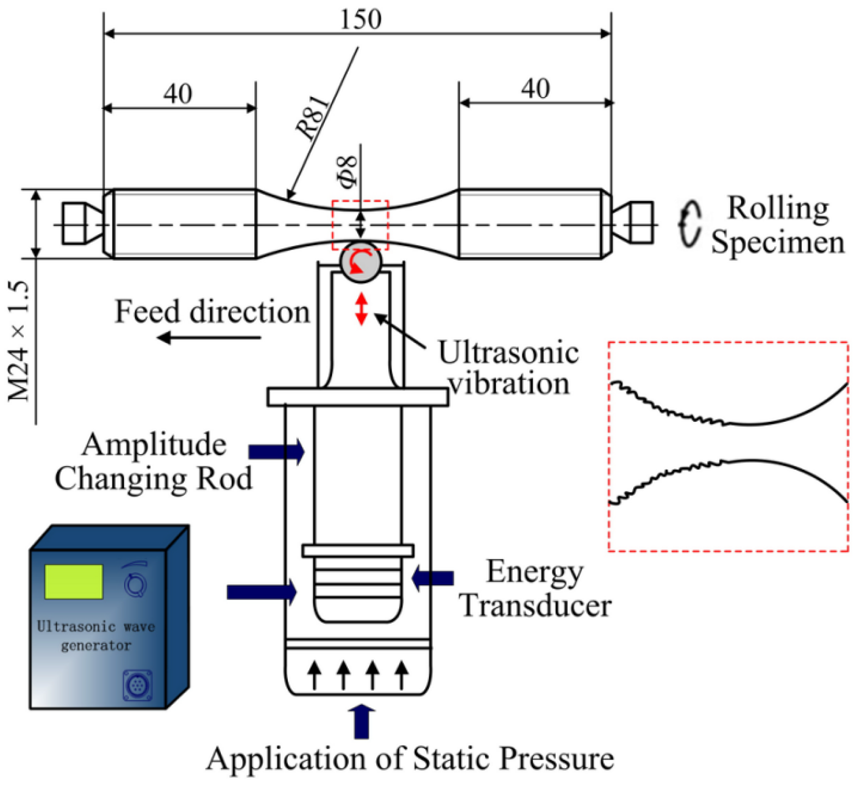
The basic principle of HFIR treatment is similar to the ultrasonic surface rolling process proposed by Wang [18,19,20]. However, HFIR has a higher frequency, which can ensure the uniformity of grain refinement. Before fatigue tests, the hour glass specimen shown in Figure 2 was treated by HFIR.

Figure 2.
The hour glass fatigue specimen and high-frequency impacting and rolling (HFIR) schematic diagram.
The detailed processing parameters include impacting frequency of ~27 kHz, an amplitude of ~7.0 μm, a rotating speed of 110 r/min, a feed quantity of 0.1 mm/r and a suitable static force. The tension-tension axial fatigue tests of as-received and HFIR specimens were performed on a 20 kN high-frequency fatigue testing machine (CIMACH, Changchun, China) under constant amplitude load with the stress ratio R = 0.5 at room temperature to evaluate the effect of the applied treatments on the fatigue strength.
2.3. Microstructure Observation
The overall appearance of the deformed layer was observed by an Axio Imager A1m type of optical microscope (OM, ZEISS, Oberkochen, Germany). The microstructures of the top surface, 80 μm and 160 μm from the treated surface were examined by a JEM-2100F type of transmission electron microscopy (TEM, JEOL, Tokyo, Japan). For TEM examination, flat specimen instead of round bar specimen was used to get the thin slices of different depths. HFIR parameters for the flat specimen are the same as those for the round bar specimen. Only rotating feed of the round bar specimen was replaced by the linear feed of the flat specimen. Fatigue fractures were investigated through a VEGA3 type of scanning electron microscope (SEM, TESCAN, Brno, Czech Republic).
2.4. Surface Roughness, Microhardness and Residual Stress Measurements
Surface roughness was detected using a 2201 type of surface roughness tester (Harbin Measuring and Cutting Tool Group Co., LTD, Harbin, China). Surface roughness (Ra) after HFIR was decreased from 1.38 down to 0.121. Such low surface roughness is hardly realized by other SPD methods. Microhardness variation from the top surface to the interior was determined by an MH-3 Vickers microhardness tester (Shanghai Hengqi Precision Machinery Plant, Shanghai, China) with a load of 100 g and loading time of 10 s. The X-ray scattering technique was used to test residual stress profiles [19].
3. Results and Discussion
3.1. Microstructure and Microhardness Distribution of the Work-Hardened Layer
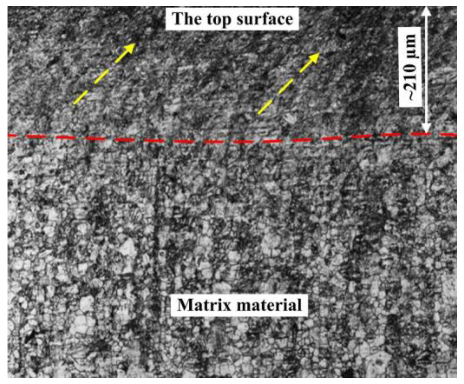
Figure 3 presents the cross-sectional microstructure of HFIR specimen. Clearly, due to the effect of high-frequency impacting, the microstructure of material surface is distinctly smaller and denser compared with that of matrix. Meanwhile, the constant rolling pressure also caused the plastic slip of the surface material, which is marked by the yellow arrows.
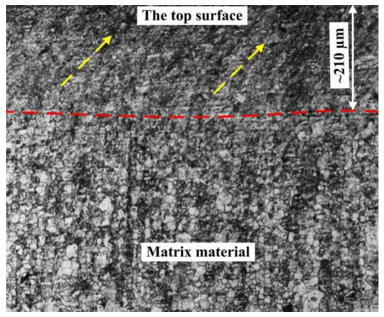
Figure 3.
The cross-sectional microstructure of the HFIR specimen.
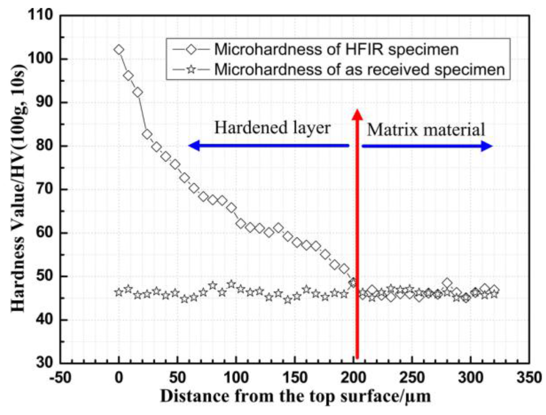
The thickness of work hardened layer is around 210 μm, which can be clearly distinguished from the matrix (see the red line in Figure 3). The thickness of the work-hardened layer was also estimated through the variation of microhardness along depth direction, as shown in Figure 4.
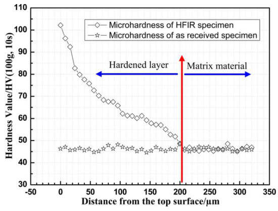
Figure 4.
The cross-sectional microhardness of as-received and HFIR specimen.
The measurement results indicated that the highest microhardness was obtained on the top surface and then decreases gradually as going into the matrix. This microhardness variation was caused by the gradient nanostructure from the top surface to the matrix.
3.2. Discussion of Surface Strengthening Mechanism
With the increase of plastic deformation, twins, dislocations and dynamic recrystallization (DRX) gradually dominate the surface nanocrystallization process, which has been studied by Lu et al. [6] based on AZ91D alloy treated by SMAT. Here, the surface strengthening process of AZ31B alloy treated by HFIR was further investigated through TEM.
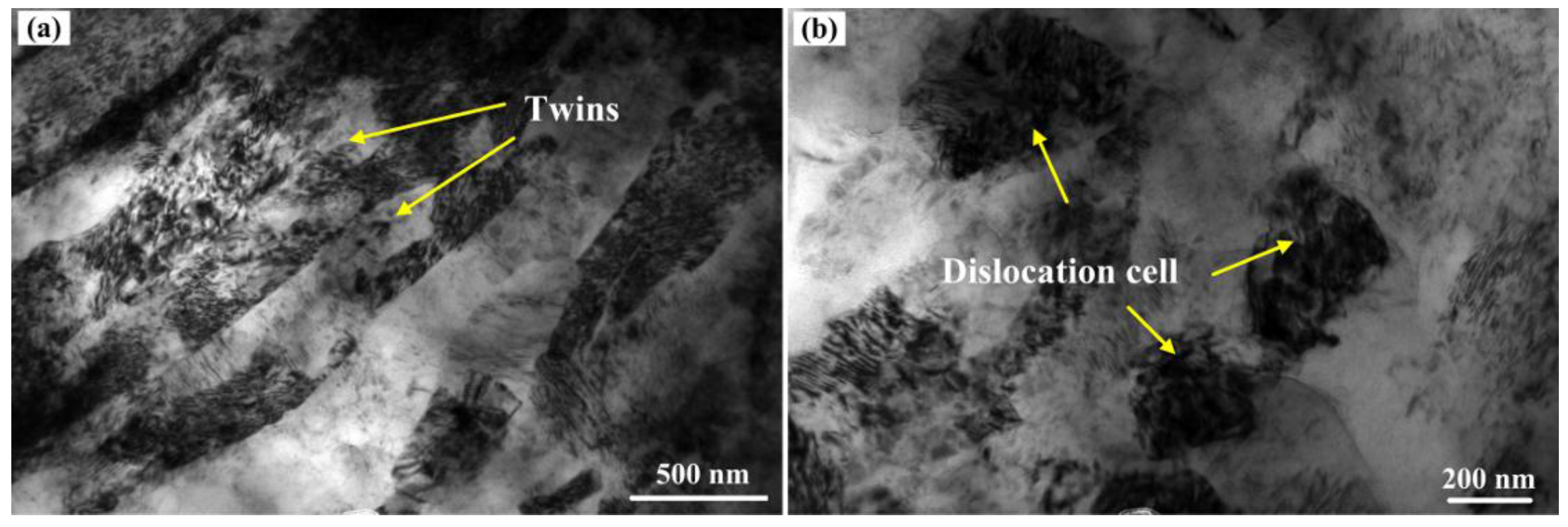
3.2.1. The 160-μm Deformed Layer from the Top Surface
The TEM bright field image at about 160 μm below the top surface of the treated AZ31B alloy is shown in Figure 5. As can be observed, the deformed twins or lath-like substructures with a width of 300–500 nm have been produced in some original grains. A large amount of dislocations and dislocation tangles can be observed in these twins or lath-like substructures in Figure 5a. In addition, dislocation cells were also found in this deformed layer (see Figure 5b). There is still a regional deformed feature under the condition of relatively homogeneous plastic deformation in the same deformed layer.
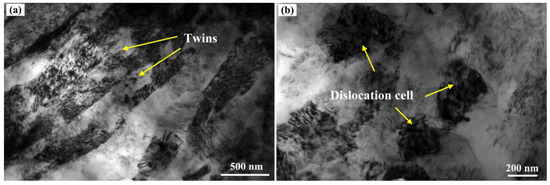
Figure 5.
TEM image of the 160-μm deformed layer from the top surface. (a) Twins and (b) dislocation cells.
3.2.2. The 80-μm Deformed Layer from the Top Surface
The TEM bright field image at about 80 μm below the top surface is shown in Figure 6. Some clear boundaries of sub-grains have been formed in this layer, and the size of sub-grains has reached around 200 nm. Meanwhile, there is a high density of dislocations and dislocation tangles around black precipitated phases in part of the sub-grains. These sub-grains will be further separated by the above high density of dislocations at the next stage. For example, the smaller Sub-grains A and B in Figure 6 have been nearly formed under the effect of dislocations activities.
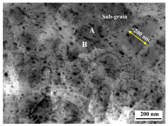
Figure 6.
TEM image of the 80-μm deformed layer from the top surface.
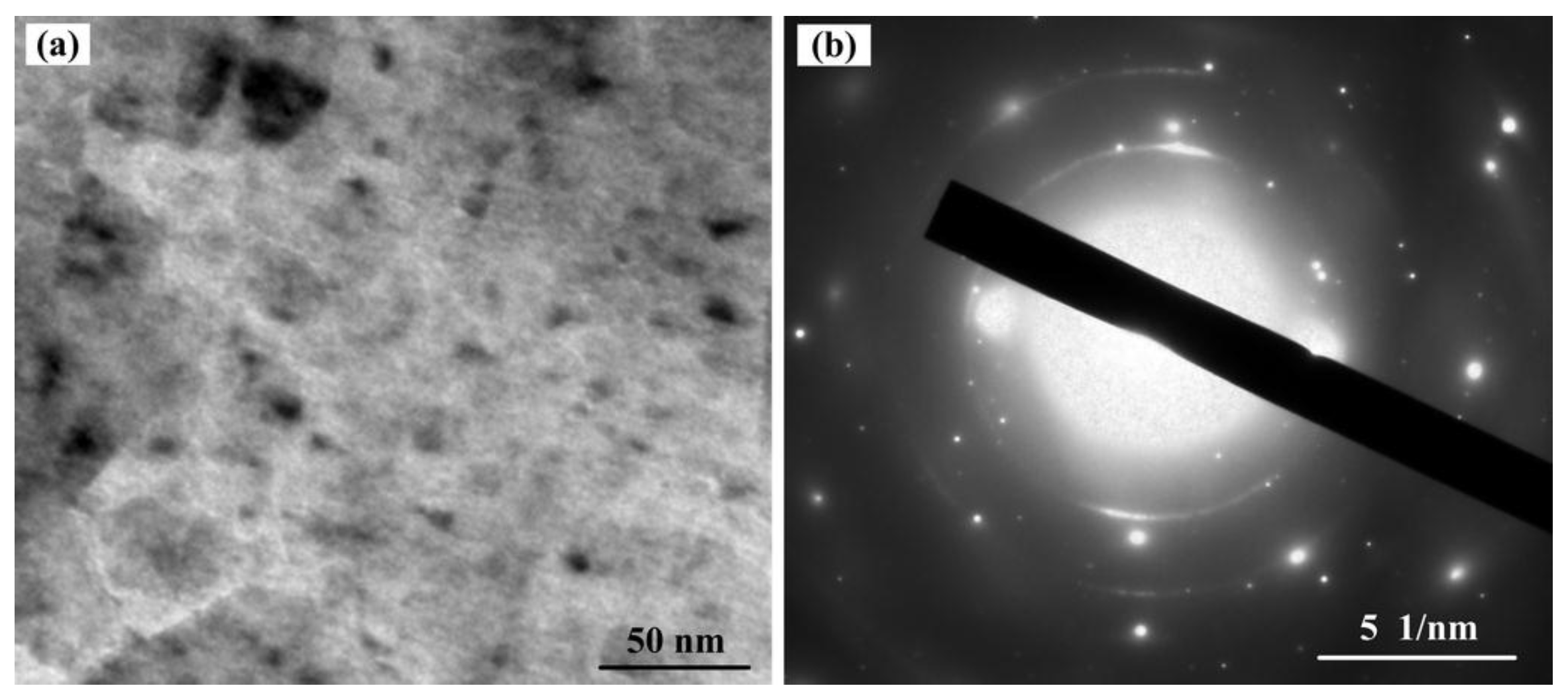
3.2.3. The Top Surface after HFIR Treatment
Figure 7 showed the TEM bright field image and corresponding selected area diffraction (SAD) pattern obtained at the top surface of HFIR specimen. The bright field image indicates that the vast majority of sub-grains have been turned into equiaxed nanocrystals with clear boundaries, and the average size is measured to be around 20 nm. As shown in Figure 7b, the SAD pattern is composed of partially continuous diffraction rings, which further confirms that as-received large crystalline grains have been broken down to nanograins at this layer.

Figure 7.
The TEM image of the top surface after HFIR treatment. (a) Nanocrystals and (b) SAD pattern corresponding to (a).
From the above TEM images, it can be concluded that the plastic deformation was governed by twinning at the early stage, and then, the non-basal dislocation slip systems were activated. With the increase of dislocation movement, sub-grains were gradually formed, and finally, nanocrystals were generated. In addition, Tan et al. [21], Myshlyaev et al. [22], Eddahbi et al. [23] and Galiyev et al. [24] reported that the DRX as an important grain refinement mechanism was observed in Mg alloys when grain size was refined to the micrometer range. Lu et al. [6] reported the effect of DRX on grain refinement of Mg alloy in the nanometer scale. HFIR has a higher impacting frequency, which can generate a higher strain rate and decrease the DRX temperature. Therefore, DRX is also an important grain refinement mechanism for the AZ31B magnesium alloy treated by HFIR technology. Figure 8 is a typical example of the newly-formed grains (A and B) in the severely deformed twin platelet near the twin interface.
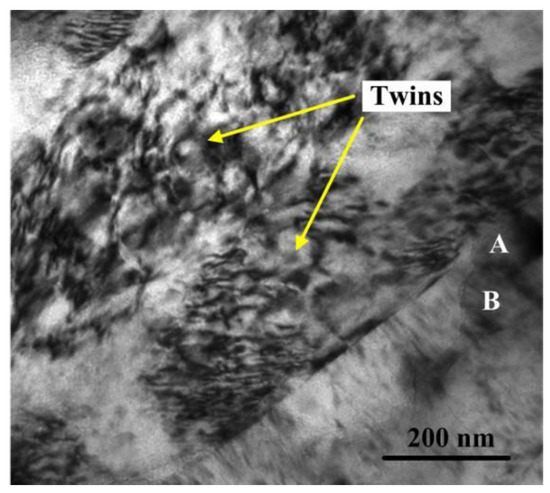
Figure 8.
The TEM bright field image of the newly-generated grains through DRX.
3.3. S-N Curves
Fatigue data (nominal stress vs. cycles) of as-received and HFIR specimens were done in a linear fit in the double logarithm coordinate (confidence level of 95%). Fatigue S-N curves of as-received and HFIR specimens are shown in Figure 9. The run-out tests are marked by arrows. The fatigue strength of HFIR and as-received specimens corresponding to 107 cycles is about 180 MPa and 140 MPa, respectively. The former shows an improvement of almost 28.6% with respect to that of the latter. Although the improvement of 28.6% is not very high compared to the results of high strength steel treated by shot peening [10,12], such improvement is still considerable because of the low absolute strength of magnesium alloy.
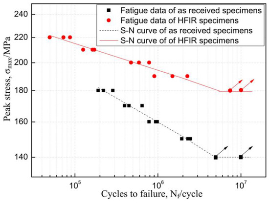
Figure 9.
S-N curves of as-received and HFIR specimens.
3.4. Discussion of Fatigue Life Improvement
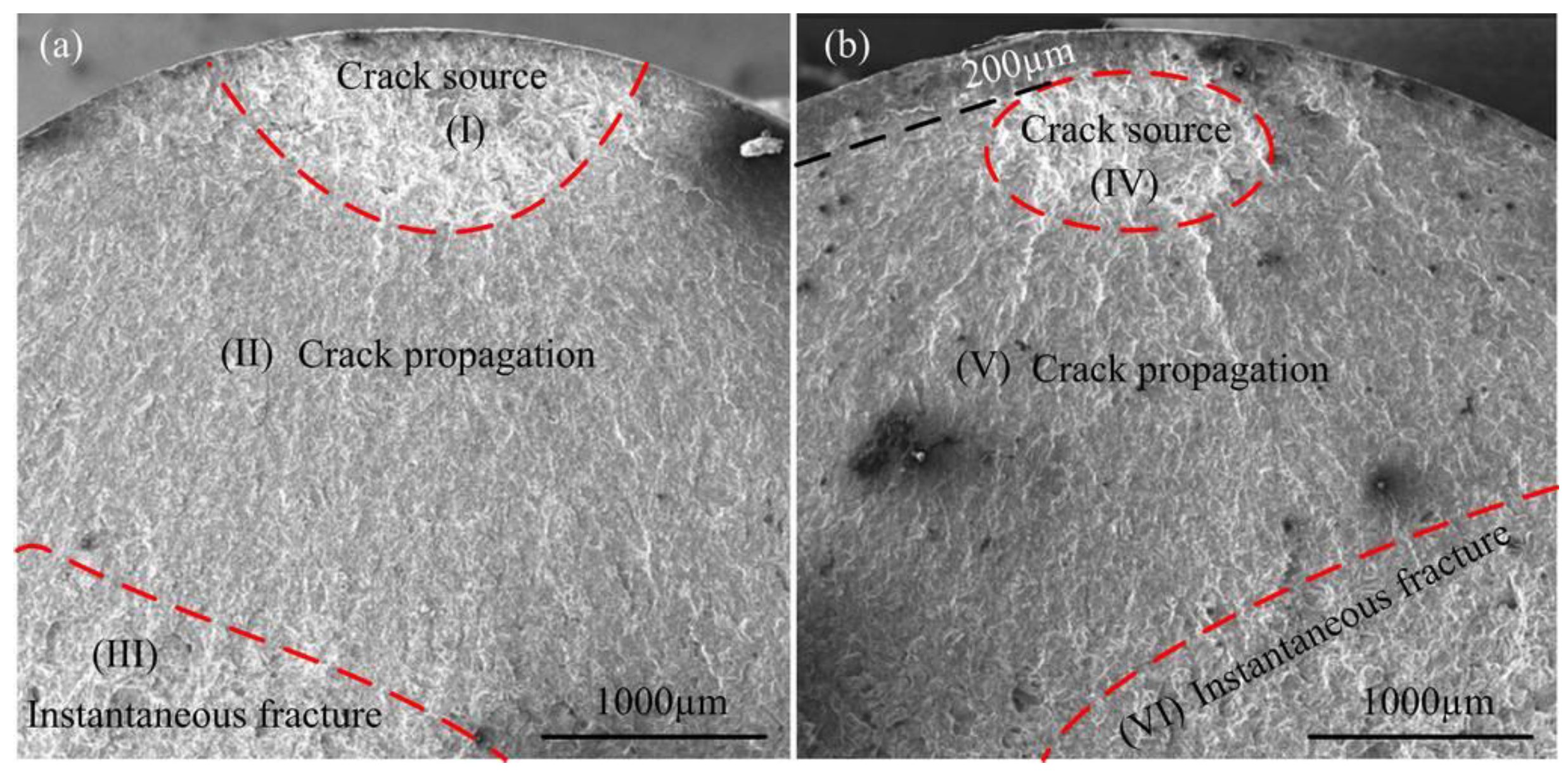
It is known that the fatigue fracture contains three stages, which are crack initiation, crack propagation and instantaneous fracture. The previous study had shown that the crack initiation stage could account for ~90% of the total fatigue life [25], and if the crack initiation point starts from the specimen interior, the fatigue properties will be significantly improved. Therefore, it is necessary to investigate the positions of fatigue crack sources of as-received and HFIR specimens. By comparing fracture surfaces of as-received and HFIR specimens, it is found that the positions of crack sources were different. All crack sources of as-received specimens initiated from the top surface (Figure 10a), while part of the crack sources of HFIR specimens initiated at the subsurface. For example, Figure 10b showed that one crack source of the HFIR specimen was found in the subsurface.
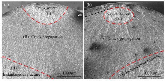
Figure 10.
Fracture surfaces of as-received and HFIR specimen. (a) as-received specimens and (b) HFIR specimens.
First, the relatively higher surface roughness or worse surface smoothness of the as-received specimen generated by machining marks can easily cause stress concentration, and the crack source was prone to form at the top surface. After HFIR, the surface roughness of the specimen was decreased to Ra = 0.121. Generally, the decrease of surface roughness will effectively reduce surface stress concentration and delay crack initiation.
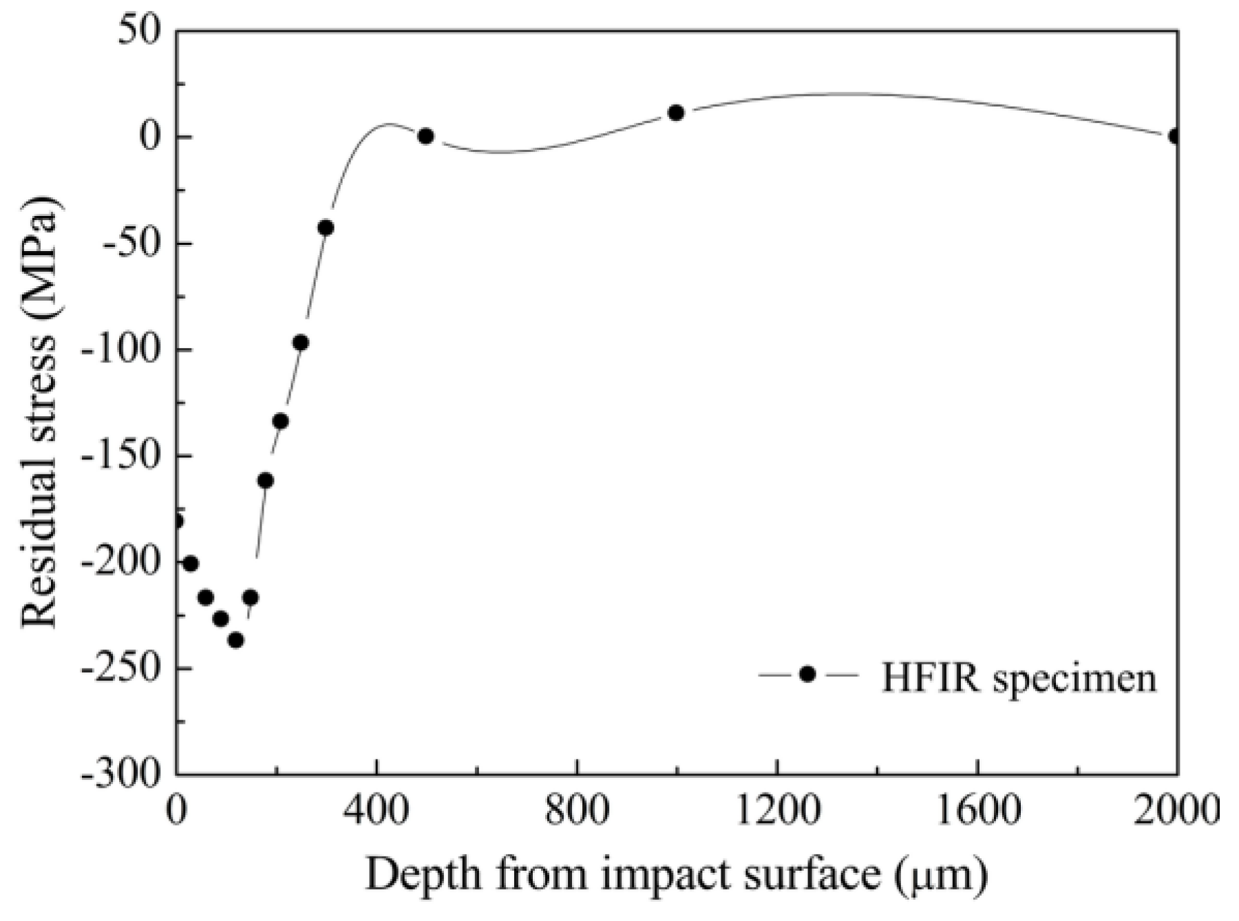
Second, except for the smooth surface, which can prolong the time of crack initiation, the in-depth residual stress also plays an important role. Figure 11 shows the residual stress distribution of the HFIR specimen. The results indicate that the top surface and subsurface of HFIR specimen are covered by the compressive residual stress, which can effectively hinder crack initiation and promote crack stopping; this viewpoint has been widely demonstrated [26,27]. Therefore, the compressive residual stress in the surface layer is a factor to change the position of the crack source and improve fatigue life.

Figure 11.
Residual stress distribution of the HFIR specimen.
In addition, McDowell Tanaka [28] illustrated that a high volume fraction of grain boundaries can stop dislocation sliding and restrain crack initiation. From Figure 6 and Figure 7, it can be seen that grain refinement is quite obvious. Therefore, the grain refinement is also a factor to improve fatigue life by stopping dislocation sliding and restraining crack initiation. As the grain refinement process continues, the work hardened layer is formed (see Figure 4). The characteristics of high dense dislocation walls, dislocation tangles and sub-grains in the hardened layer can result in a lower crack propagation rate, which has been proven by Suresh and Li [25,26]. Thus, the work hardening is also a factor to influence fatigue life.
As we know, there are many methods related to fatigue life prediction and assessment [29,30]. However, in order to predict and evaluate the main factors that improve fatigue life after HFIR treatment, the correction formula of Baghrifard and Guagliano [31,32] based on the Eichlseder approach [30] by considering the ratio of the Cs coefficient and the ratio of FWHM for shot-peened specimen was referenced and described in Equation (1) [31].
where is the fatigue limit; is the fatigue limit in tension; is the fatigue limit in bending; is the relative stress gradient (RSG); is the material parameter; b is the size parameter of the specimen; is the full width at half maximum of the peening specimen; is the full width at half maximum of the non-peening specimen; is the surface roughness of the peening specimen; is the surface roughness of the non-peening specimen.
High-frequency impacting and rolling, the same as shot peening, also belongs to the surface strengthening method. Equation (1) is the fatigue criteria corresponding to the notched specimen. The ratio of the Cs coefficient and the ratio of FWHM are irrelevant to the stress gradient. Therefore, the effect rule of the ratio of Cs coefficient and the ratio of FWHM on fatigue life are also fit for the non-notched specimen.
The surface strain hardening index of FWHM was obtained from XRD analysis. In this study, the FWHM value of the HFIR specimen was improved by 20.1% compared to that of the as-received specimen. From Figure 9, we can know that HFIR specimens showed a fatigue strength improvement of almost 28.6% with respect to that of as-received specimens. Therefore, the work hardening is the most important factor to improve the fatigue properties of the HFIR specimen in this study.
As for the Cs coefficient, the surface of the as-received specimen before fatigue tests was polished by fine sandpaper along the axial direction of the specimen. Although the value of surface roughness is still larger, the micro-marks are parallel to the axial direction. For the tensile-tensile axial fatigue test, micro-marks in the axial direction will not produce a greater effect on the fatigue crack initiation.
For the residual stress, the value of compressive residual stress on the top surface of the magnesium alloy specimen treated by HFIR is lower than that of the high strength steel specimen treated by HFIR, and the compressive residual stress is easily relaxed when a random or occasional high load appears during fatigue tests.
To be sure, the smooth surface and compressive residual stress generated by HFIR played a positive role to improve fatigue life, but their effects are not the most important. The work hardening caused by HFIR is the key factor to influence the fatigue properties of magnesium alloy in this study.
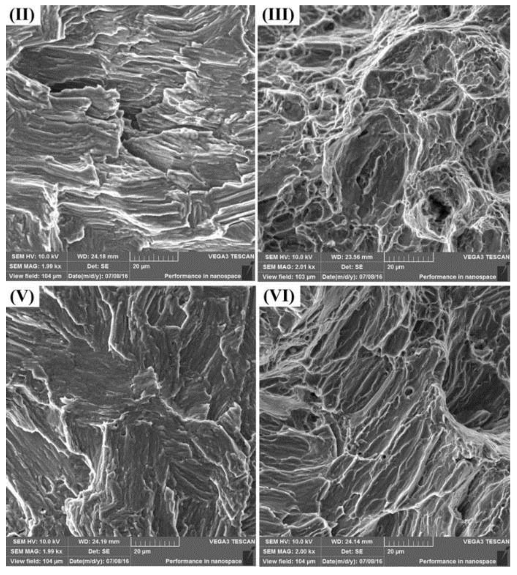
3.5. Fatigue Fracture Process
The effect of the fatigue crack initiation stage on fatigue life has been systematically discussed in the previous section. As for the crack propagation and instantaneous fracture stages, the images corresponding to Figure 10 are shown in Figure 12. For the as-received specimen, fatigue cracks propagated in terms of the transcrystalline and crack propagation region presented fine striations. The orientation of fatigue striations is consistent and perpendicular to the direction of the crack propagation (Figure 12II). However, for the HFIR specimen, the orientation of the fatigue striations is relatively random due to the complex stress state in the subsurface (Figure 12V). The instantaneous fracture stages of the as-received and the HFIR specimen are characterized by transcrystalline ductile fracture with an equiaxed (Figure 12III) and tearing (Figure 12VI) type of dimple morphology, respectively.

Figure 12.
The high magnification images of as-received and HFIR specimens corresponding to Figure 10. (II) Crack propagation region of as-received specimen and (III) Instantaneous fracture region of as-received specimen. (V) Crack propagation region of HFIR specimen and (VI) Instantaneous fracture region of HFIR specimens.
4. Conclusions
The present work investigates the surface nano-enhanced mechanism and fatigue properties of AZ31B magnesium alloy subjected to HFIR treatment. After HFIR, grain refinement, work hardening, compressive residual stress and a smooth surface were induced on the surface of specimen. Grains were refined to equiaxed nanocrystals with an average size of 20 nm. The fatigue strength of HFIR specimens corresponding to 107 cycles was increased by 28.6% compared to that of as-received specimens. All crack sources of the as-received specimen initiated from the top surface, while part of the crack sources of the HFIR specimen initiated at the subsurface. The work hardening caused by HFIR is the most important factor to influence fatigue properties.
This study proved that the surface nano-enhanced method based on HFIR technology will have a good industrial application value in the prolonging life field.
Acknowledgments
This work was supported by the National Natural Science Foundation of China under Grant No. 51405182.
Author Contributions
Yanjun Zhang conceived and designed the experiments; Xiaohui Zhao, Yanjun Zhang, and Yu Liu performed the experiments, analyzed the data, and wrote the paper.
Conflicts of Interest
The authors declare no conflict of interest.
References
- Asgari, H.; Szpunar, J.A.; Odeshi, A.G.; Zeng, L.J.; Olsson, E. Experimental and simulation analysis of texture formation and deformation mechanism of rolled AZ31B magnesium alloy under dynamic loading. Mater. Sci. Eng. A 2014, 618, 310–322. [Google Scholar] [CrossRef]
- Li, Z.M.; Wang, Q.G.; Luo, A.A.; Fu, P.H.; Peng, L.M. Fatigue strength dependence on the ultimate tensile strength and microhardness in magnesium alloys. Int J. Fatigue 2015, 80, 468–476. [Google Scholar] [CrossRef]
- Dogan, E.; Vaughan, M.W.; Wang, S.J.; Karaman, I.; Proust, G. Role of starting texture and deformation modes on low-temperature shear formability and shear localization of Mg-3Al-1Zn alloy. Acta Mater. 2015, 89, 408–422. [Google Scholar] [CrossRef]
- Karimi, A.; Amini, S. Steel 7225 surface ultrafine structure and improvement of its mechanical properties using surface nanocrystallization technology by ultrasonic impact. Int. J. Adv. Manuf. Technol. 2016, 83, 1127–1134. [Google Scholar] [CrossRef]
- Manafi, B.; Saeidi, M. Development of a novel severe plastic deformation method: Friction stir equal channel angular pressing. Int. J. Adv. Manuf. Technol. 2016, 86, 1367–1374. [Google Scholar] [CrossRef]
- Sun, H.Q.; Shi, Y.N.; Zhang, M.X.; Lu, K. Plastic strain-induced grain refinement in the nanometer scale in a Mg alloy. Acta Mater. 2007, 55, 975–982. [Google Scholar] [CrossRef]
- Trško, L.; Bokůvka, O.; Novýa, F.; Guagliano, M. Effect of severe shot peening on ultra-high-cycle fatigue of a low-alloy steel. Mater. Des. 2014, 57, 103–113. [Google Scholar] [CrossRef]
- Fernández-Pariente, I.; Bagherifard, S.; Guagliano, M.; Ghelichi, R. Fatigue behavior of nitrided and shot peened steel with artificial small surface defects. Eng. Fract. Mech. 2013, 103, 2–9. [Google Scholar] [CrossRef]
- Bagheri, S.; Guagliano, M. Review of shot peening processes to obtain nanocrystalline surfaces in metal alloys. Surf. Eng. 2009, 25, 3–14. [Google Scholar] [CrossRef]
- Gao, Y.K. Influence of shot peening on tension-tension fatigue property of two high strength Ti alloys. Surf. Eng. 2006, 22, 299–303. [Google Scholar] [CrossRef]
- Gao, Y.; Lu, F.; Yao, M. Influence of mechanical surface treatments on fatigue property of 30CrMnSiNi2A steel. Surf. Eng. 2005, 21, 325–328. [Google Scholar] [CrossRef]
- Arakawa, J.; Kakuta, M.; Hayashi, Y.; Tanegashima, R.; Akebono, H.; Kato, M.; Sugeta, A. Fatigue strength of USP treated ASTM CA6NM for hydraulic turbine runner. Surf. Eng. 2014, 30, 662–669. [Google Scholar] [CrossRef]
- Bagherifard, S.; Fernandez-Pariente, I.; Ghelichi, R.; Guagliano, M. Effect of severe shot peening on microstructure and fatigue strength of cast iron. Int. J. Fatigue 2014, 65, 64–70. [Google Scholar] [CrossRef]
- Malaki, M.; Ding, H.T. A review of ultrasonic peening treatment. Mater. Des. 2015, 87, 1072–1086. [Google Scholar] [CrossRef]
- Tsai, W.Y.; Huang, J.C.; Gao, Y.J.; Chung, Y.L.; Huang, G.R. Relationship between microstructure and properties for ultrasonic surface mechanical attrition treatment. Scr. Mater. 2015, 103, 45–48. [Google Scholar] [CrossRef]
- Moering, J.; Ma, X.L.; Chen, G.Z.; Miao, P.F.; Li, G.Z.; Qian, G.; Mathaudhu, S.; Zhu, Y.T. The role of shear strain on texture and microstructural gradients in low carbon steel processed by Surface Mechanical Attrition Treatment. Scr. Mater. 2015, 108, 100–103. [Google Scholar] [CrossRef]
- Pu, Z.; Yang, S.; Song, G.L.; Dillon, O.W., Jr.; Puleo, D.A.; Jawahir, I.S. Ultrafine-grained surface layer on Mg-Al-Zn alloy produced by cryogenic burnishing for enhanced corrosion resistance. Scr. Mater. 2011, 65, 520–523. [Google Scholar] [CrossRef]
- Liu, Y.; Zhao, X.H.; Wang, D.P. Determination of the plastic properties of materials treated by ultrasonic surface rolling process through instrumented indentation. Mater. Sci. Eng. A 2014, 600, 21–31. [Google Scholar] [CrossRef]
- Wang, T.; Wang, D.P.; Liu, G. Investigations on the nanocrystallization of 40Cr using ultrasonic surface rolling processing. Appl. Surf. Sci. 2008, 255, 1824–1829. [Google Scholar]
- Liu, Y.; Zhao, X.H.; Wang, D.P. Effective FE model to predict surface layer characteristics of ultrasonic surface rolling with experimental validation. Mater. Sci. Technol. 2014, 30, 627–636. [Google Scholar] [CrossRef]
- Tan, J.C.; Tan, M.J. Dynamic continuous recrystallization characteristics in two stage deformation of Mg-3Al-1Zn alloy sheet. Mater. Sci. Eng. A 2003, 339, 124–132. [Google Scholar] [CrossRef]
- Myshlyaev, M.M.; McQueen, H.J.; Mwembela, A.; Konopleva, E. Twinning, dynamic recovery and recrystallization in hot worked Mg-Al-Zn alloy. Mater. Sci. Eng. A 2002, 337, 121–133. [Google Scholar] [CrossRef]
- Eddahbi, M.; del Valle, J.A.; Pérez-Prado, M.T.; Ruano, O.A. Comparison of the microstructure and thermal stability of an AZ31 alloy processed by ECAP and large strain hot rolling. Mater. Sci, Eng. A 2005, 410, 308–311. [Google Scholar] [CrossRef]
- Galiyev, A.; Kaibyshev, R.; Gottstein, G. Correlation of plastic deformation and dynamic recrystallization in magnesium alloy ZK60. Acta Mater. 2001, 49, 1199–1207. [Google Scholar] [CrossRef]
- Suresh, S. Fatigue of Materials; Cambridge University Press: Cambridge, UK, 1998. [Google Scholar]
- Li, D.; Chen, H.N.; Xu, H. The effect of nanostructured surface layer on the fatigue behaviors of a carbon steel. Appl. Surf. Sci. 2009, 255, 3811–3816. [Google Scholar] [CrossRef]
- De los Rios, E.R.; Trull, M.; Levers, A. Modelling fatigue crack growth in shot-peened components of Al 2024-T351. Fatigue Fract. Eng. Mater. Struct. 2000, 23, 709–716. [Google Scholar] [CrossRef]
- McDowell, D.L.; Dunne, F.P.E. Microstructure-sensitive computational modeling of fatigue crack formation. Int. J. Fatigue 2010, 32, 1521–1542. [Google Scholar] [CrossRef]
- Zhu, S.P.; Lei, Q.; Huang, H.Z.; Yang, Y.J.; Peng, W.W. Mean stress effect correction in strain energy-based fatigue life prediction of metals. Int. J. Damage Mech. 2016. [Google Scholar] [CrossRef]
- Eichlseder, W. Fatigue analysis by local stress concept based on finite elementsresults. Comput. Struct. 2002, 80, 2109–2113. [Google Scholar] [CrossRef]
- Bagherifard, S.; Guagliano, M. Application of different fatigue strength criteria on shot peenednotched parts. Part 2: Nominal and local stress approaches. Appl. Surf. Sci. 2014, 289, 173–179. [Google Scholar] [CrossRef]
- Bagherifard, S.; Colombo, C.; Guagliano, M. Application of different fatigue strength criteria to shot peenednotched components. Part 1: Fracture Mechanics based approaches. Appl. Surf. Sci. 2014, 289, 180–187. [Google Scholar] [CrossRef]


© 2017 by the authors. Licensee MDPI, Basel, Switzerland. This article is an open access article distributed under the terms and conditions of the Creative Commons Attribution (CC BY) license ( http://creativecommons.org/licenses/by/4.0/).