Microstructure Analysis of Neutron Absorber Al/B4C Metal Matrix Composites


Abstract
:1. Introduction
2. Experiment
3. Results and Discussion
4. Conclusions
- (1)
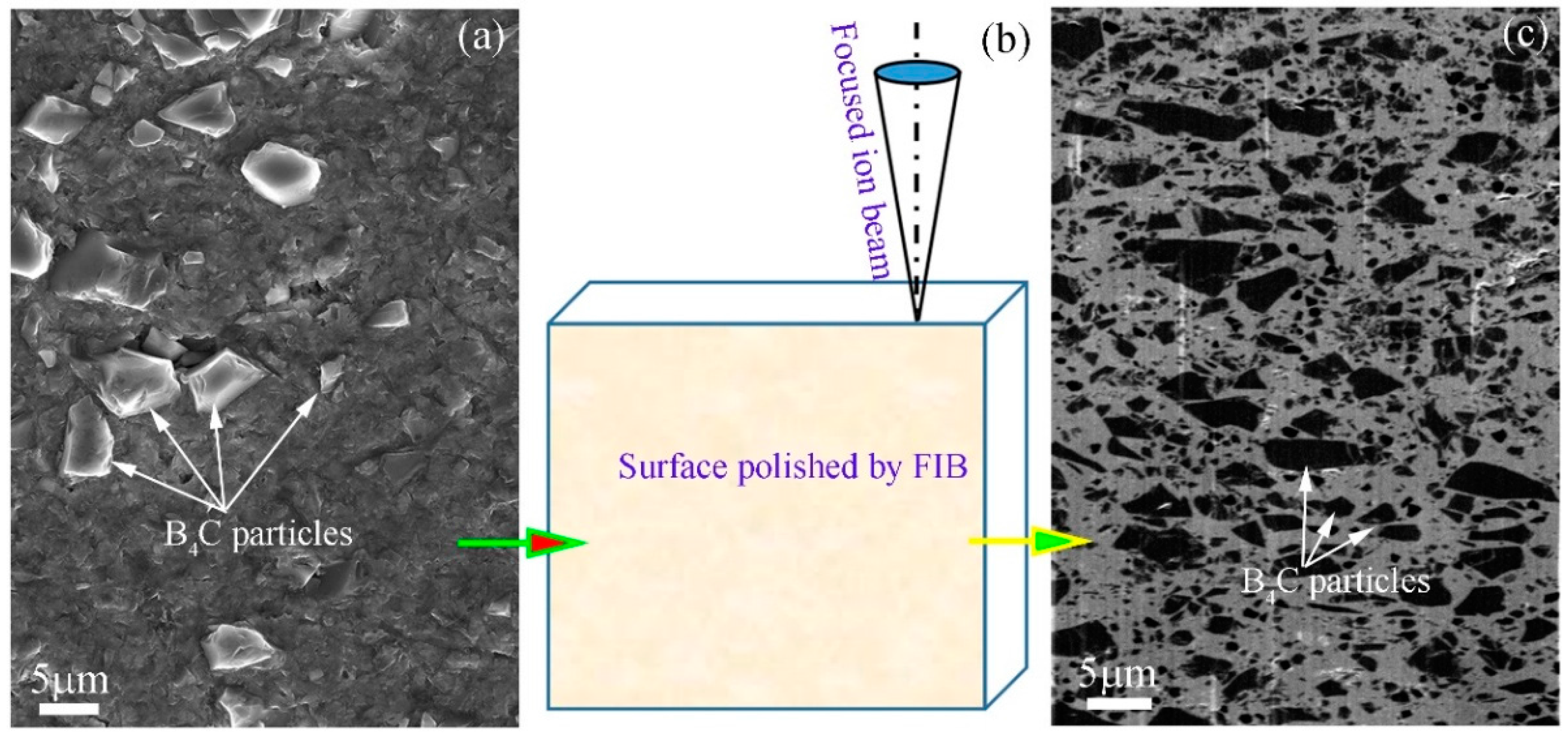
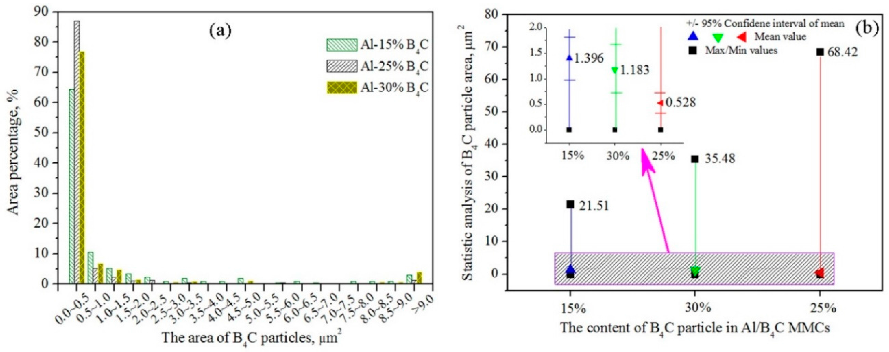
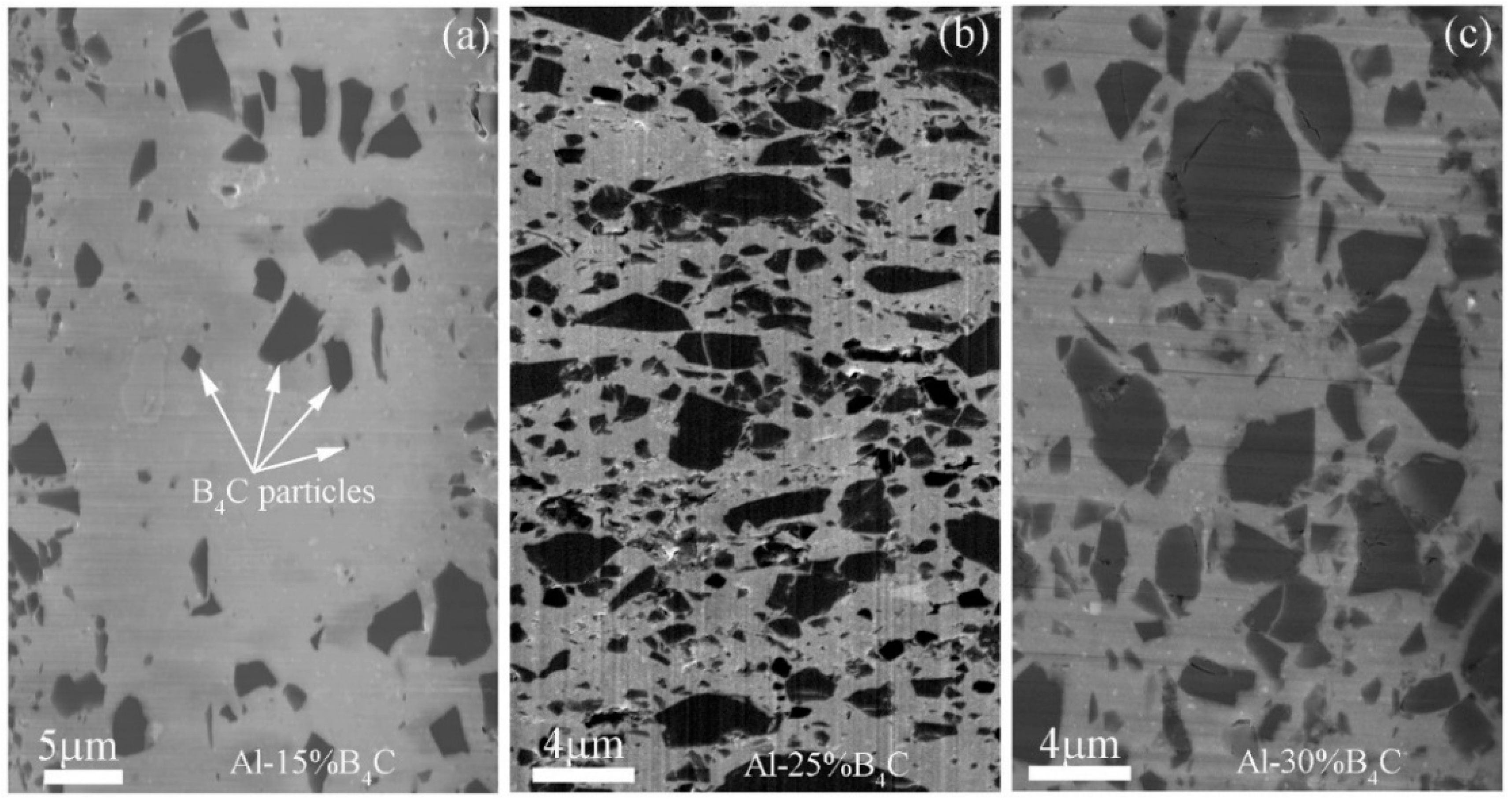
- The size of B4C particles ranging from several hundred nanometers to several microns were not uniform. The statistical results showed that the area of B4C particles mainly ranged from 0 to 0.5 μm2, which was the proportion of 64.29%, 86.99% and 76.86% of total statistical results for the Al-15%B4C, Al-25%B4C and Al-30%B4C MMCs, respectively. The average area of B4C particles in the Al-15%B4C, Al-25%B4C and Al-30%B4C MMCs were about 1.396 μm2, 0.528 μm2 and 1.183 μm2, respectively.
- (2)
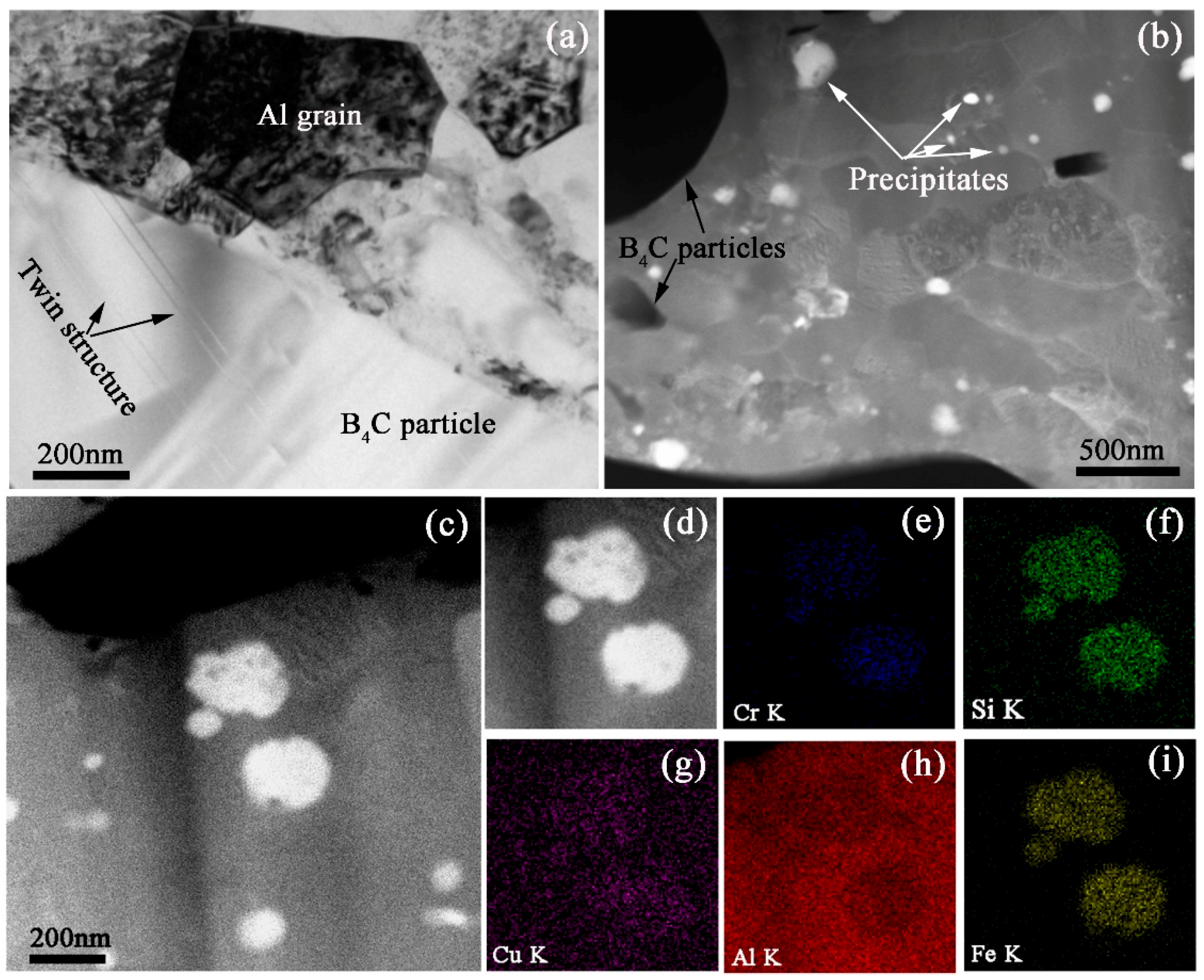
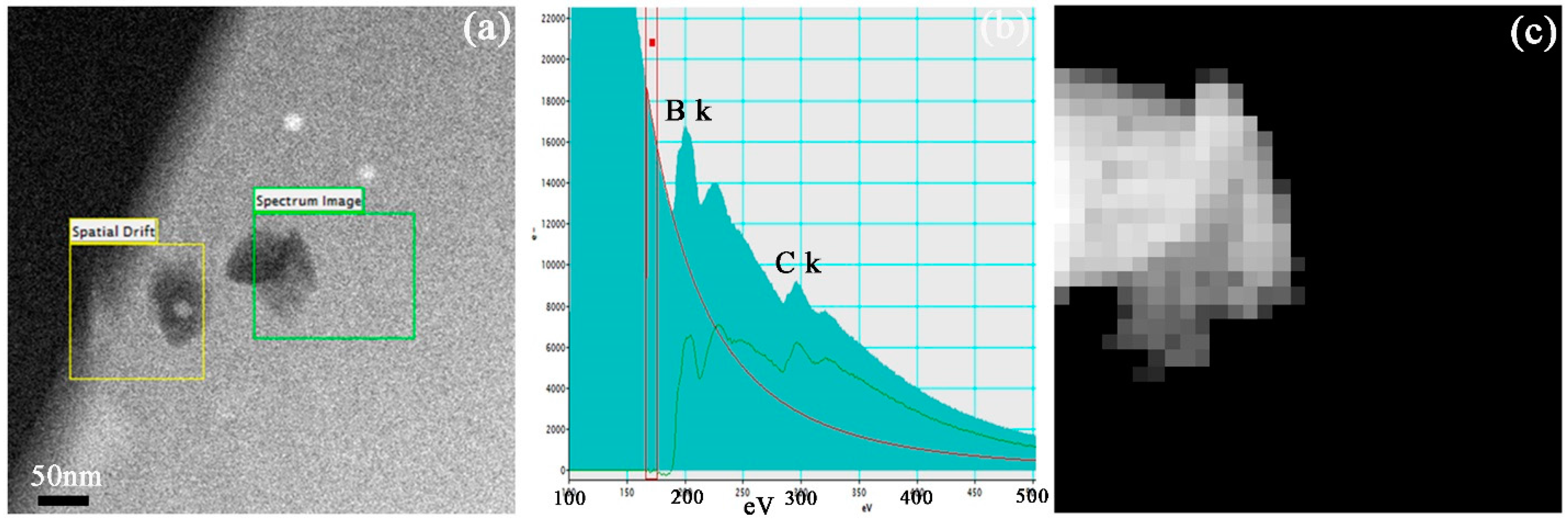
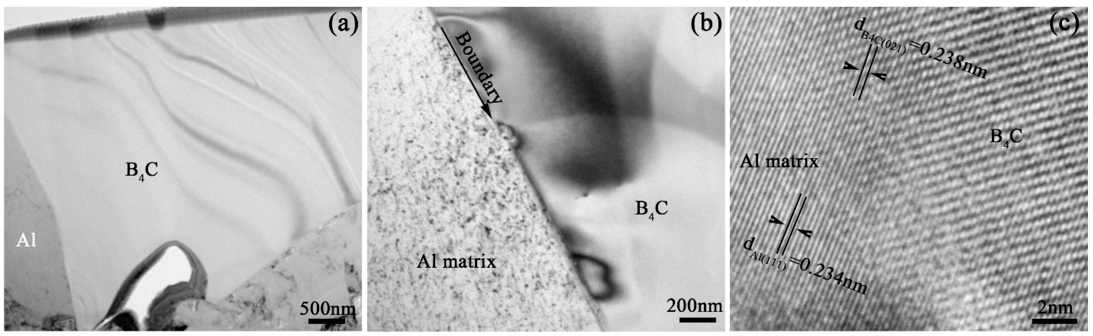
- The nanoscale precipitates were analyzed by the element mappings in STEM mode and EELS mode, which included elliptic alloy precipitates with elemental Cu, Cr, Fe and Si, except for Al, and B4C nanoparticles with polygonal shape. The interface characteristics showed that the (021) crystal plane of B4C particle and (111) crystal plane of Al matrix grew together. The lattice mismatch was approximately 1.68%.
- (3)
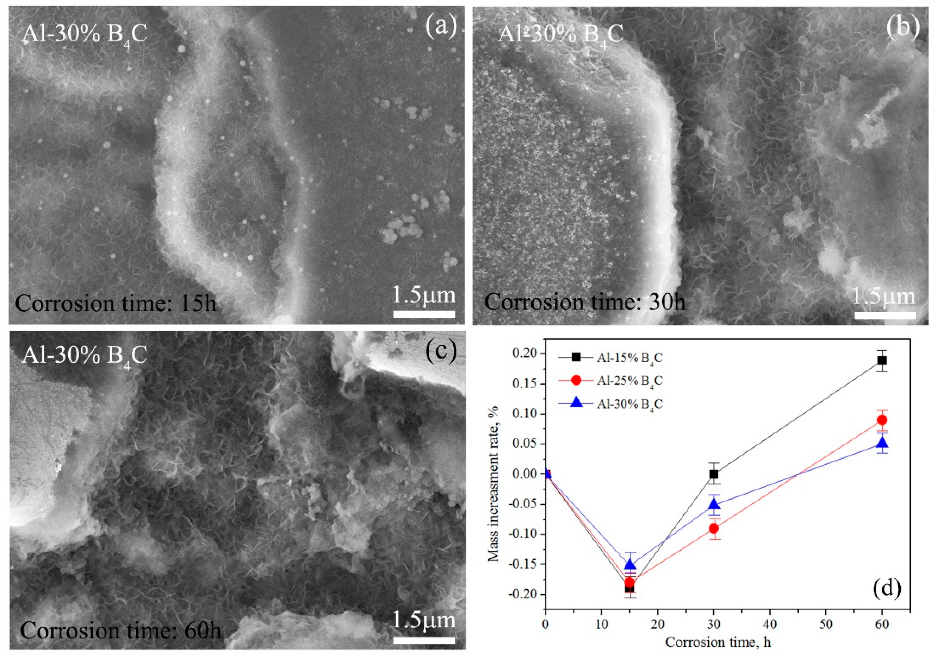
- A large amount of flocculent oxide and pit etching were formed in the sample surface after chemical corrosion. The mass increment rate was first decreased with increasing corrosion time and then increased. When the corrosion time was larger than 15 h, the mass increment was Δm (Al-30%B4C) < Δm (Al-25%B4C) < Δm (Al-15%B4C).
Acknowledgments
Author Contributions
Conflicts of Interest
References
- Nuclear Regulatory Commission. Spent Fuel Storage in Pools and Dry Casks Key Points and Questions & Answers. Available online: https://www.nrc.gov/waste/spent-fuel-storage/faqs.html (accessed on 14 November 2017).
- Lakosi, L.; Nguyen, C.T. Gamma and fast neutron radiation monitoring inside spent reactor fuel assemblies. Nucl. Instrum. Methods Phys. Res. B 2007, 580, 788–791. [Google Scholar] [CrossRef]
- Jostsons, A.; Dubose, C.K.H. Microstructure of boron carbide after fast neutron irradiation. J. Nucl. Mater. 1972, 44, 91–95. [Google Scholar] [CrossRef]
- Stoto, T.; Ardonceau, J.; Zuppiroli, L.; Castiglioni, M. Behaviour of implanted helium in boron carbide in the temperature range 750 to 1720° C. Radiat. Eff. 1987, 105, 17–30. [Google Scholar] [CrossRef]
- Zhang, F.; Wang, X.; Wierschke, J.B.; Wang, L. Helium bubble evolution in ion irradiated Al/B4C metal metrix composite. Scr. Mater. 2015, 109, 28–33. [Google Scholar] [CrossRef]
- Lai, J.; Zhang, Z.; Chen, X.G. The thermal stability of mechanical properties of Al–B4C composites alloyed with Sc and Zr at elevated temperatures. Mater. Sci. Eng. A 2012, 532, 462–470. [Google Scholar] [CrossRef]
- Hollenberg, G.W.; Cummings, W.V. Effect of fast neutron irradiation on the structure of boron carbide. J. Am. Ceram. Soc. 1977, 60, 520–525. [Google Scholar] [CrossRef]
- Takako, D.; Yoshiaki, T.; Naoaki, A.; Shoji, O.; Manabu, S.; Yuko, M. Neutron irradiation effects on 11B4C and recovery by annealing. J. Ceram. Soc. Jpn. 2007, 115, 551–555. [Google Scholar]
- Ashbee, K.H.G.; Dubose, C.K.H. Dislocation nodes in boron carbide, with special reference to non-stoichiometry. Acta Metall. 1972, 20, 241–245. [Google Scholar] [CrossRef]
- Gosset, D.; Miro, S.; Doriot, S.; Victor, G.; Motte, V. Evidence of amorphisation of B 4 C boron carbide under slow, heavy ion irradiation. Nucl. Instrum. Methods Phys. Res. 2015, 365, 300–304. [Google Scholar] [CrossRef]
- Luo, Z.; Song, Y.; Zhang, S.; Miller, D.J. Interfacial microstructure in a B4C/Al composite fabricated by pressureless infiltration. Metall. Mater. Trans. A 2012, 43, 281–293. [Google Scholar] [CrossRef]
- Ibrahim, M.F.; Ammar, H.R.; Samuel, A.M.; Soliman, M.S.; Almajid, A.; Samuel, F.H. Mechanical properties and fracture of Al-15 vol.-% B4C based metal matrix composites. Int. J. Cast Met. Res. 2014, 27, 7–14. [Google Scholar] [CrossRef]
- Shorowordi, K.M.; Laoui, T.; Haseeb, A.S.; Celis, J.P.; Froyen, L. Microstructure and interface characteristics of B4C, SiC and Al2O3 reinforced Al matrix composites: A comparative study. J. Mater. Process. Technol. 2003, 142, 738–743. [Google Scholar] [CrossRef]
- Ye, J.; He, J.; Schoenung, J.M. Cryomilling for the Fabrication of a Particulate B4C Reinforced Al Nanocomposite: Part I. Effects of Process Conditions on Structure. Metall. Mater. Trans. A 2005, 37, 3099–3109. [Google Scholar] [CrossRef]
- Zhang, P.; Li, Y.; Wang, W.; Gao, Z.; Wang, B. The design, fabrication and properties of B4C/Al neutron absorbers. J. Nucl. Mater. 2013, 437, 350–358. [Google Scholar] [CrossRef]
- Alizadeh, M.; Alizadeh, M.; Amini, R. Structural and mechanical properties of Al/B4C composites fabricated by wet attrition milling and hot extrusion. J. Mater. Sci. Technol. 2013, 29, 725–730. [Google Scholar] [CrossRef]
- Viala, J.C.; Bouix, J.; Gonzalez, G.; Esnouf, C. Chemical reactivity of aluminium with boron carbide. J. Mater. Sci. 1997, 32, 4559–4573. [Google Scholar] [CrossRef]
- Zaykova-Feldman, L.; Moore, T.M. The total release method for FIB in-situ TEM sample preparation. Microsc. Microanal. 2005, 11 (Suppl. 2), 848–849. [Google Scholar] [CrossRef]
- Alizadeh, M. Comparison of nanostructured Al/B4C composite produced by ARB and Al/B4C composite produced by RRB process. Mater. Sci. Eng. A 2010, 528, 578–582. [Google Scholar] [CrossRef]
- Ran, G.; Zhou, J.; Wang, Q.G. The effect of hot isostatic pressing on the microstructure and tensile properties of an unmodified A356-T6 cast aluminum alloy. J. Alloys Compd. 2006, 421, 80–86. [Google Scholar] [CrossRef]
- Li, Y.; Zhao, Y.H.; Liu, W.; Zhang, Z.H.; Vogt, R.G.; Lavernia, E.J.; Schoenung, J.M. Deformation twinning in boron carbide particles within nanostructured Al 5083/B4C metal matrix composites. Philos. Mag. 2010, 90, 783–792. [Google Scholar] [CrossRef]
- Heian, E.M.; Khalsa, S.K.; Lee, J.W.; Munir, Z.A.; Yamamoto, T.; Ohyanagi, M. Synthesis of Dense, High-Defect-Concentration B4C through Mechanical Activation and Field-Assisted Combustion. J. Am. Ceram. Soc. 2004, 87, 779–783. [Google Scholar] [CrossRef]
- Ye, J.; Lee, Z.; Ahn, B.; Nutt, S.R.; He, J.; Schoenung, J.M. Cryomilling for the fabrication of a particulate B4C reinforced Al nanocomposite: Part II. Mechanisms for microstructural evolution. Metall. Mater. Trans. A 2006, 37, 3111–3117. [Google Scholar] [CrossRef]


| Elements | Ba | Cr | Cu | Fe | Mg | Mn | Pb | Si | Ti | Zn | Zr |
|---|---|---|---|---|---|---|---|---|---|---|---|
| Al-15%B4C | 0.00021 | 0.1213 | 0.1248 | 0.9415 | 0.2135 | 0.0904 | 0.1042 | 0.3560 | 0.0115 | 0.0342 | 0.0204 |
| Al-25%B4C | 0.00031 | 0.1054 | 0.1084 | 0.3967 | 0.0674 | 0.0853 | 0.0911 | 0.2347 | 0.0101 | 0.0280 | 0.0042 |
| Al-30%B4C | 0.00067 | 0.0825 | 0.1034 | 0.2979 | 0.2225 | 0.0835 | 0.0851 | 0.2091 | 0.0095 | 0.0275 | 0.0041 |
| Materials | 0 h | 15 h | 30 h | 60 h |
|---|---|---|---|---|
| Al-15%B4C | 0 | −0.189 | 0.0 | 0.189 |
| Al-25%B4C | 0 | −0.180 | −0.090 | 0.090 |
| Al-30%B4C | 0 | −0.152 | −0.051 | 0.051 |
© 2017 by the authors. Licensee MDPI, Basel, Switzerland. This article is an open access article distributed under the terms and conditions of the Creative Commons Attribution (CC BY) license (http://creativecommons.org/licenses/by/4.0/).
Share and Cite
Lin, J.; Ran, G.; Lei, P.; Ye, C.; Huang, S.; Zhao, S.; Li, N. Microstructure Analysis of Neutron Absorber Al/B4C Metal Matrix Composites. Metals 2017, 7, 567. https://doi.org/10.3390/met7120567
Lin J, Ran G, Lei P, Ye C, Huang S, Zhao S, Li N. Microstructure Analysis of Neutron Absorber Al/B4C Metal Matrix Composites. Metals. 2017; 7(12):567. https://doi.org/10.3390/met7120567
Chicago/Turabian StyleLin, Jianxin, Guang Ran, Penghui Lei, Chao Ye, Shilin Huang, Shangquan Zhao, and Ning Li. 2017. "Microstructure Analysis of Neutron Absorber Al/B4C Metal Matrix Composites" Metals 7, no. 12: 567. https://doi.org/10.3390/met7120567
APA StyleLin, J., Ran, G., Lei, P., Ye, C., Huang, S., Zhao, S., & Li, N. (2017). Microstructure Analysis of Neutron Absorber Al/B4C Metal Matrix Composites. Metals, 7(12), 567. https://doi.org/10.3390/met7120567