
Gas Metal Arc Welding Using Novel CaO-Added Mg Alloy Filler Wire


Abstract
:
1. Introduction
2. Experimental Setup
3. Welding Characteristics
4. Fume Generation and Droplet Transfer
5. Conclusions
- (1)
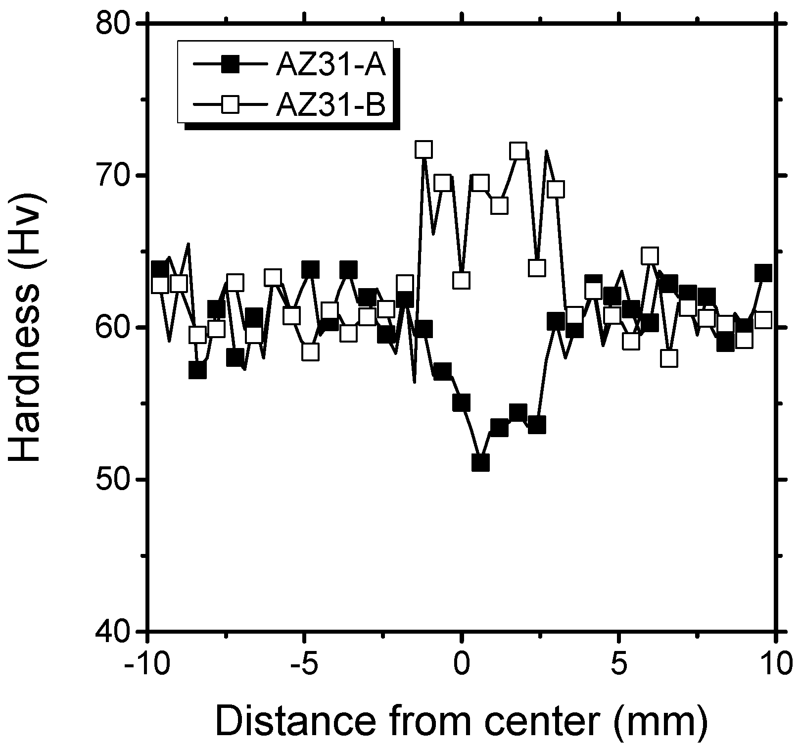
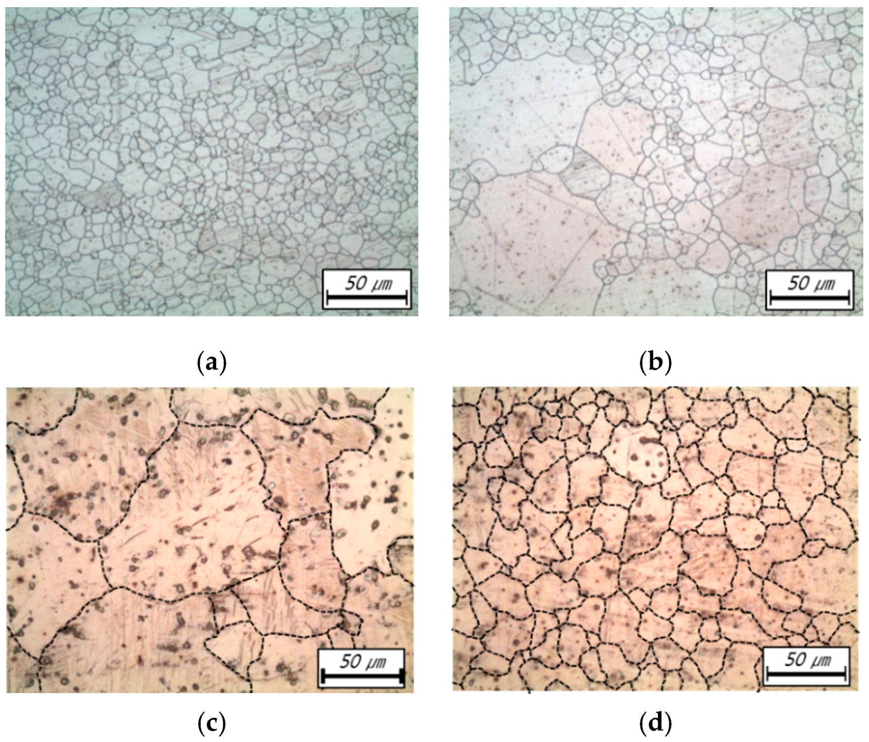
- The tensile strength of weldments was slightly increased by using the CaO-added AZ31 filler wire. By adding CaO, the grain size in the weld metal decreased from 59.9 μm to 20.4 μm, and the average hardness in the weld metal increased from 55.3 Hv to 68.9 Hv.
- (2)
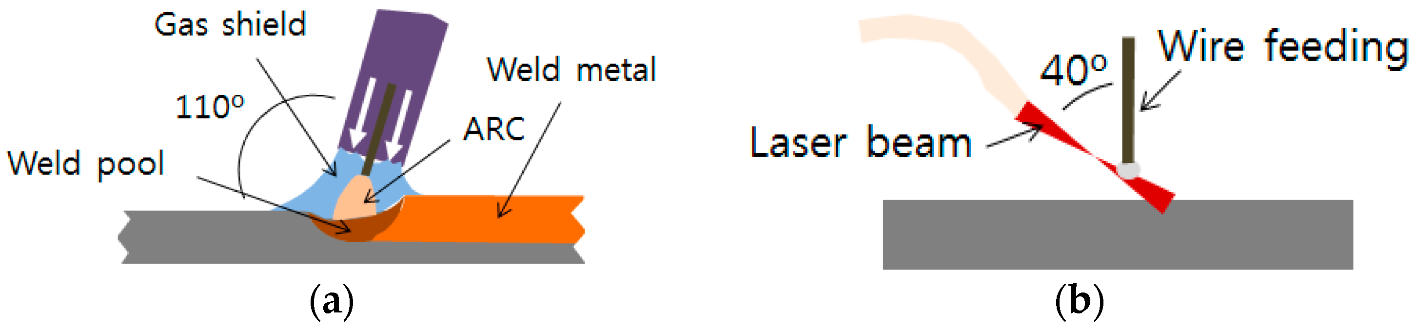
- Welding fumes were successfully suppressed during the CMT mode welding. The fume suppression was due to the burning resistance of CaO-added Mg alloy, and this has been confirmed by using the laser melting test.
- (3)
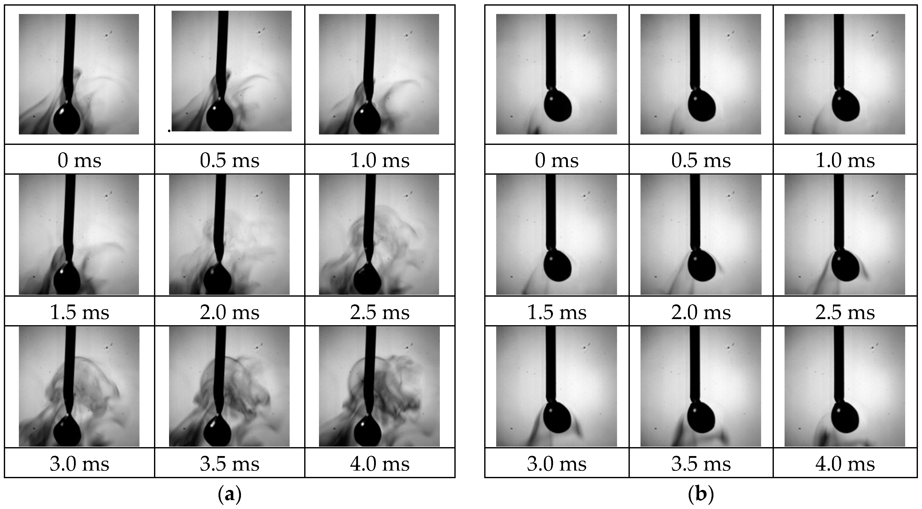
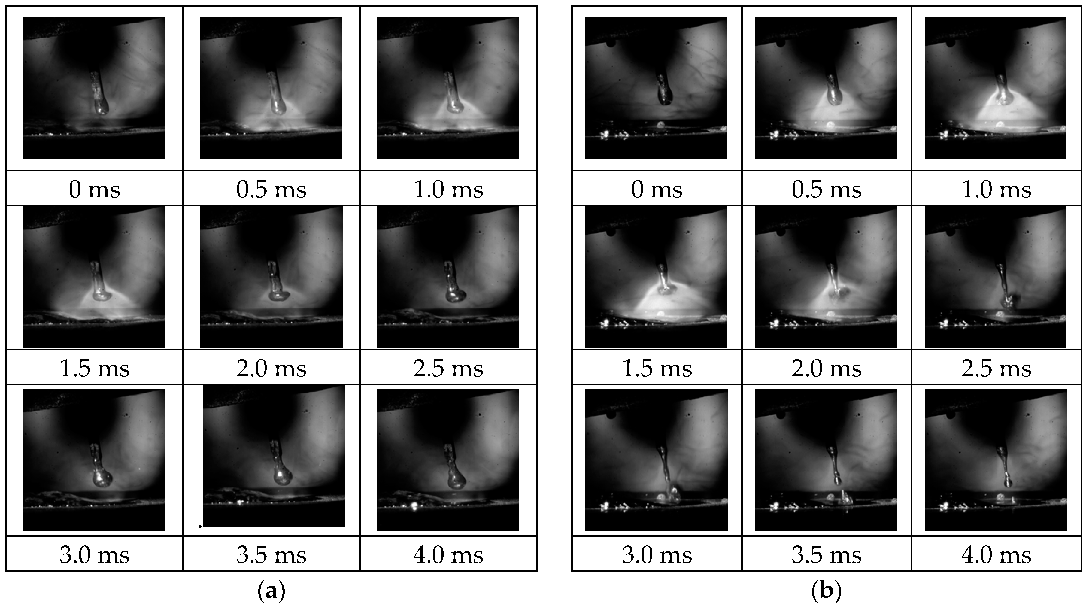
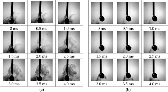
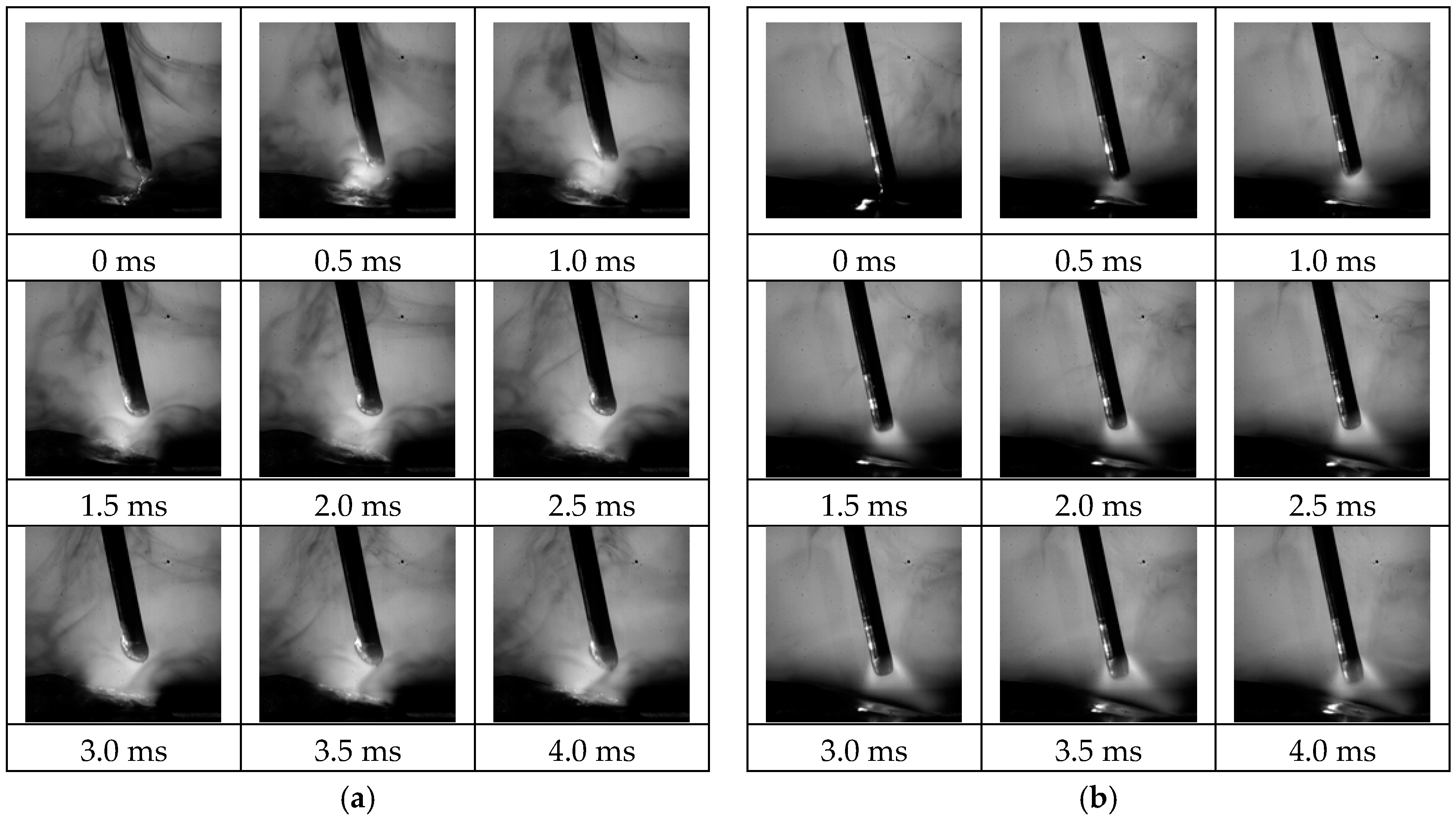
- In the pulse mode welding, spray transfer mode welding was achieved, which enabled stable droplet transfer. Also, the suppression of spatter was expected because of the small droplet size and fast transfer time.
Author Contributions
Conflicts of Interest
References
- Lee, J.K.; Yoon, Y.O.; Kim, S.K. Development of environment-friendly CaO added AZ31 Mg alloy. Solid State Phenom. 2007, 124, 1481–1484. [Google Scholar] [CrossRef]
- Ha, S.-H.; Lee, J.-K.; Kim, S.K. Effect of CaO on oxidation resistance and microstructure of pure Mg. Mater. Trans. 2008, 49, 1081–1083. [Google Scholar] [CrossRef]
- Lee, J.-K.; Kim, S.K. Effect of CaO composition on oxidation and burning behaviors of AM50 Mg alloy. Trans. Nonferrous Met. Soc. China 2011, 21, 23–27. [Google Scholar] [CrossRef]
- Lee, D.B. High temperature oxidation of AZ31 + 0.3 wt. % Ca and AZ31 + 0.3 wt. % CaO magnesium alloys. Corros. Sci. 2013, 70, 243–251. [Google Scholar] [CrossRef]
- Kim, S.K. Design and development of high-performance Eco-Mg alloys. In Magnesium Alloys-Design, Processing and Properties; Czerwinski, F., Ed.; InTech: Rijeka, Croatia, 2011; pp. 431–468. [Google Scholar]
- Nam, T.H.; Kim, S.H.; Kim, J.G.; Kim, S.K. Corrosion resistance of extruded Mg-3Al-1Zn alloy manufactured by adding CaO for the replacement of the protective gases. Mater. Corros. 2014, 65, 577–581. [Google Scholar] [CrossRef]
- Nam, N.; Bian, M.; Forsyth, M.; Seter, M.; Tan, M.; Shin, K. Effect of calcium oxide on the corrosion behaviour of AZ91 magnesium alloy. Corros. Sci. 2012, 64, 263–271. [Google Scholar] [CrossRef]
- Esparza, J.; Davis, W.; Trillo, E.; Murr, L. Friction-stir welding of magnesium alloy AZ31B. J. Mater. Sci. Lett. 2002, 21, 917–920. [Google Scholar] [CrossRef]
- Park, S.H.C.; Sato, Y.S.; Kokawa, H. Effect of micro-texture on fracture location in friction stir weld of Mg alloy AZ61 during tensile test. Scr. Mater. 2003, 49, 161–166. [Google Scholar] [CrossRef]
- Carlone, P.; Palazzo, G. Characterization of TIG and FSW weldings in cast ZE41A magnesium alloy. J. Mater. Process. Technol. 2015, 215, 87–94. [Google Scholar] [CrossRef]
- Carlone, P.; Astarita, A.; Rubino, F.; Pasquino, N. Microstructural Aspects in FSW and TIG Welding of Cast ZE41A Magnesium Alloy. Metall. Mate. Trans. B 2016, 47, 1340–1346. [Google Scholar] [CrossRef]
- Liu, L.; Dong, C. Gas tungsten-arc filler welding of AZ31 magnesium alloy. Mater. Lett. 2006, 60, 2194–2197. [Google Scholar] [CrossRef]
- Liu, L.-M.; Cai, D.-H.; Zhang, Z.-D. Gas tungsten arc welding of magnesium alloy using activated flux-coated wire. Scr. Mater. 2007, 57, 695–698. [Google Scholar] [CrossRef]
- Wagner, D.; Yang, Y.; Kou, S. Spatter and porosity in gas-metal arc welding of magnesium alloys: Mechanisms and elimination. Weld. J. 2013, 92, 347–362. [Google Scholar]
- Cao, X.; Jahazi, M.; Immarigeon, J.; Wallace, W. A review of laser welding techniques for magnesium alloys. J. Mater. Process. Technol. 2006, 171, 188–204. [Google Scholar] [CrossRef]
- Liu, L.; Wang, J.; Song, G. Hybrid laser—TIG welding, laser beam welding and gas tungsten arc welding of AZ31B magnesium alloy. Mater. Sci. Eng. A 2004, 381, 129–133. [Google Scholar]
- Choi, D.H.; Ahn, B.W.; Kim, S.K.; Yeon, Y.M.; Kim, Y.J.; Park, S.-K.; Jung, S.B. Microstructure evaluation of friction stir welded AZ 91 with CaO Mg alloy. Mater. Trans. 2011, 52, 802–805. [Google Scholar] [CrossRef]
- Choi, D.-H.; Kim, S.-K.; Jung, S.-B. The microstructures and mechanical properties of friction stir welded AZ31 with CaO Mg alloys. J. Alloy. Compd. 2013, 554, 162–168. [Google Scholar] [CrossRef]
- Kang, M.; Kim, C. Effect of CaO contents on Yb:YAG disk laser weldability of AZ31 Mg alloy. Mater. Sci. Forum 2015, 804, 31–34. [Google Scholar] [CrossRef]
- Wang, J.; Nishimura, H.; Katayma, S.; Mizutani, M. Evaporation phenomena of magnesium from droplet at welding wire tip in pulsed MIG arc welding of aluminium alloys. Sci. Technol. Weld. Join. 2011, 16, 418–425. [Google Scholar] [CrossRef]
- Kim, C.-H.; Ahn, Y.-N.; Lee, K.-B. Droplet transfer during conventional gas metal arc and plasma-gas metal arc hybrid welding with Al 5183 filler metal. Curr. Appl. Phys. 2012, 12, 178–183. [Google Scholar] [CrossRef]
- Semenov, I.; Krivtsun, I.; Demchenko, V.; Semenov, A.; Reisgen, U.; Mokrov, O.; Zabirov, A. Modelling of binary alloy (Al-Mg) anode evaporation in arc welding. Model. Simul. Mater. Sci. Eng. 2012, 20. [Google Scholar] [CrossRef]
- Reisgen, U.; Mokrov, O.; Zabirov, A.; Krivtsun, I.; Demchenko, V.; Lisnyi, O.; Semenov, I. Task of volumetrical evaporation and behaviour of droplets in pulsed MIG welding of AlMg alloys. Weld. World 2013, 57, 507–514. [Google Scholar] [CrossRef]
- Fatemi-Varzaneh, S.; Zarei-Hanzaki, A.; Beladi, H. Dynamic recrystallization in AZ31 magnesium alloy. Mater. Sci. Eng. A 2007, 456, 52–57. [Google Scholar] [CrossRef]
- Chae, H.; Kim, C.; Kim, J.; Rhee, S. Fume generation behaviors in short circuit mode during gas metal arc welding and flux cored arc welding. Mater. Trans. 2006, 47, 1859–1863. [Google Scholar] [CrossRef]
- Kim, Y.; Eagar, T. Analysis of metal transfer in gas metal arc welding. Weld. J. 1993, 72, 269–278. [Google Scholar]


| Al | Zn | Mn | Si | Fe | Cr | Mg |
|---|---|---|---|---|---|---|
| 3.098 | 0.981 | 0.304 | 0.037 | 0.013 | 0.013 | Bal. |
| Filler Wire | Al | Zn | Mn | Si | Ca | Mg |
|---|---|---|---|---|---|---|
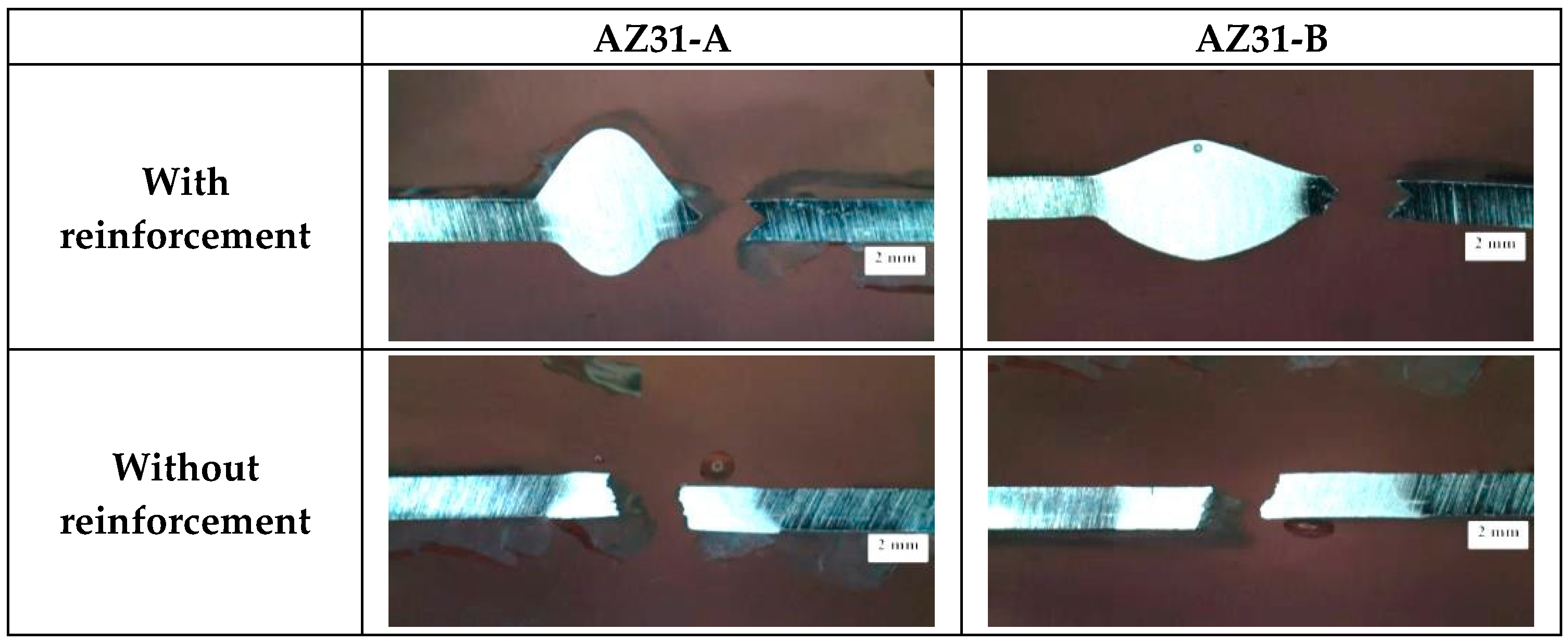
| AZ31-A | 2.76 | 0.92 | 0.40 | 0.019 | - | Bal. |
| AZ31-B | 3.10 | 0.63 | 0.19 | 1.18 | 0.89 | Bal. |
© 2016 by the authors; licensee MDPI, Basel, Switzerland. This article is an open access article distributed under the terms and conditions of the Creative Commons Attribution (CC-BY) license (http://creativecommons.org/licenses/by/4.0/).
Share and Cite
Kang, M.; Ahn, Y.; Kim, C. Gas Metal Arc Welding Using Novel CaO-Added Mg Alloy Filler Wire. Metals 2016, 6, 155. https://doi.org/10.3390/met6070155
Kang M, Ahn Y, Kim C. Gas Metal Arc Welding Using Novel CaO-Added Mg Alloy Filler Wire. Metals. 2016; 6(7):155. https://doi.org/10.3390/met6070155
Chicago/Turabian StyleKang, Minjung, Youngnam Ahn, and Cheolhee Kim. 2016. "Gas Metal Arc Welding Using Novel CaO-Added Mg Alloy Filler Wire" Metals 6, no. 7: 155. https://doi.org/10.3390/met6070155
APA StyleKang, M., Ahn, Y., & Kim, C. (2016). Gas Metal Arc Welding Using Novel CaO-Added Mg Alloy Filler Wire. Metals, 6(7), 155. https://doi.org/10.3390/met6070155