Article

Corrosion Behavior of AlSi10Mg Alloy Produced by Additive Manufacturing (AM) vs. Its Counterpart Gravity Cast Alloy

Department of Materials Engineering, Ben-Gurion University of the Negev, P.O. Box 652, Beer-Sheva 8410501, Israel
*
Author to whom correspondence should be addressed.
Metals 2016, 6(7), 148; https://doi.org/10.3390/met6070148
Submission received: 19 May 2016 / Revised: 23 June 2016 / Accepted: 27 June 2016 / Published: 30 June 2016

Abstract

:
The attractiveness of additive manufacturing (AM) relates to the ability of this technology to rapidly produce very complex components at affordable costs. However, the properties and corrosion behavior, in particular, of products produced by AM technology should at least match the properties obtained by conventional technologies. The present study aims at evaluating the corrosion behavior and corrosion fatigue endurance of AlSi10Mg alloy produced by selective laser melting (SLM) in comparison with its conventional counterpart, gravity cast alloy. The results obtained indicate that the corrosion resistance of the printed and cast alloys was relatively similar, with a minor advantage to the printed alloy. The corrosion fatigue endurance of the printed alloy was relatively improved compared to the cast alloy. This was mainly attributed to the significant differences between the microstructure and defect characteristics of those two alloys.

Graphical Abstract

1. Introduction

Additive manufacturing (AM) technology has gained increased attention in the last decade due to its potential to produce complex net shape structures with small tolerances, attractive cost, and a relatively short time to market [1,2]. The selective laser melting (SLM) process is part of this technology which employs a high energy laser beam to selectively melt a powder bed metal layer-by-layer according to predesigned CAD software [3,4].
Light structural materials and Al alloys in particular are widely used in the transportation and electronic industries owing to their high specific strength [5]. Further benefits of Al alloys relate to their relative advantage in terms of ductility, heat transfer, electrical conductivity, and corrosion resistance in regular atmospheric conditions. However, Al-base components produced by the SLM process are known to have high surface roughness (8–20 µm) which is generated mainly due to balling and dross formation in the melt pool [6]. This surface morphology may promote the inherent sensitivity of those alloys to localized corrosion attack, especially in the presence of chloride [7,8].
AlSi10Mg is the most commonly used Al alloy for the SLM process, mainly due to its solidification characteristics and relatively reduced coefficient of thermal expansion [9]. However, knowledge of its corrosion performance in regular service conditions is extremely limited. The present study aims at evaluating the corrosion behavior and corrosion fatigue endurance of AlSi10Mg alloy produced by the SLM process in comparison with its conventional counterpart, gravity cast Al alloy A360.2 which has a very similar chemical composition. This comparison study can highlight the differences between printed and cast alloys in terms of corrosion performance and may present an indication of the maturity of printed Al-base components to serve as adequate structural material for commercial applications.

2. Materials and Methods
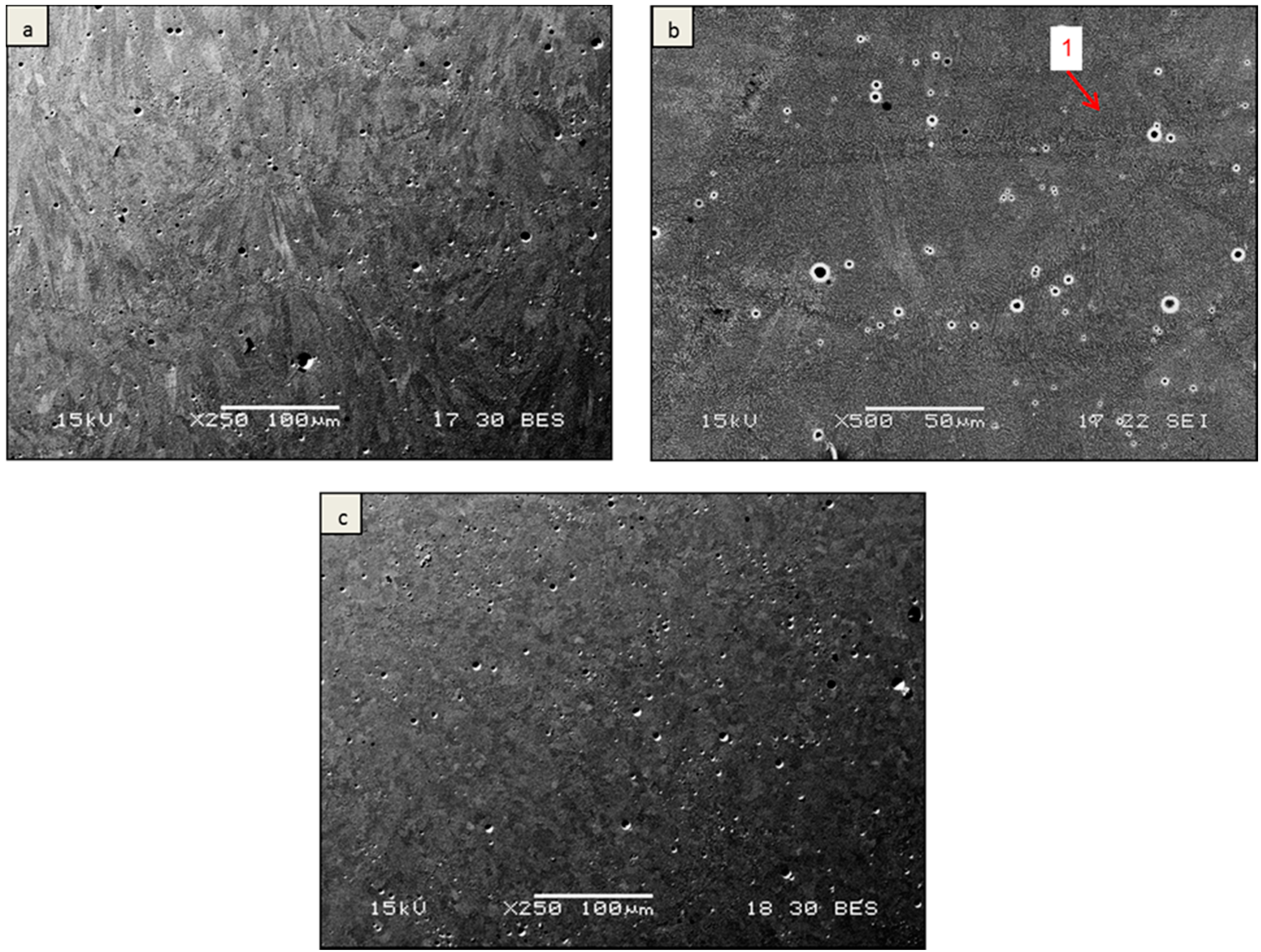
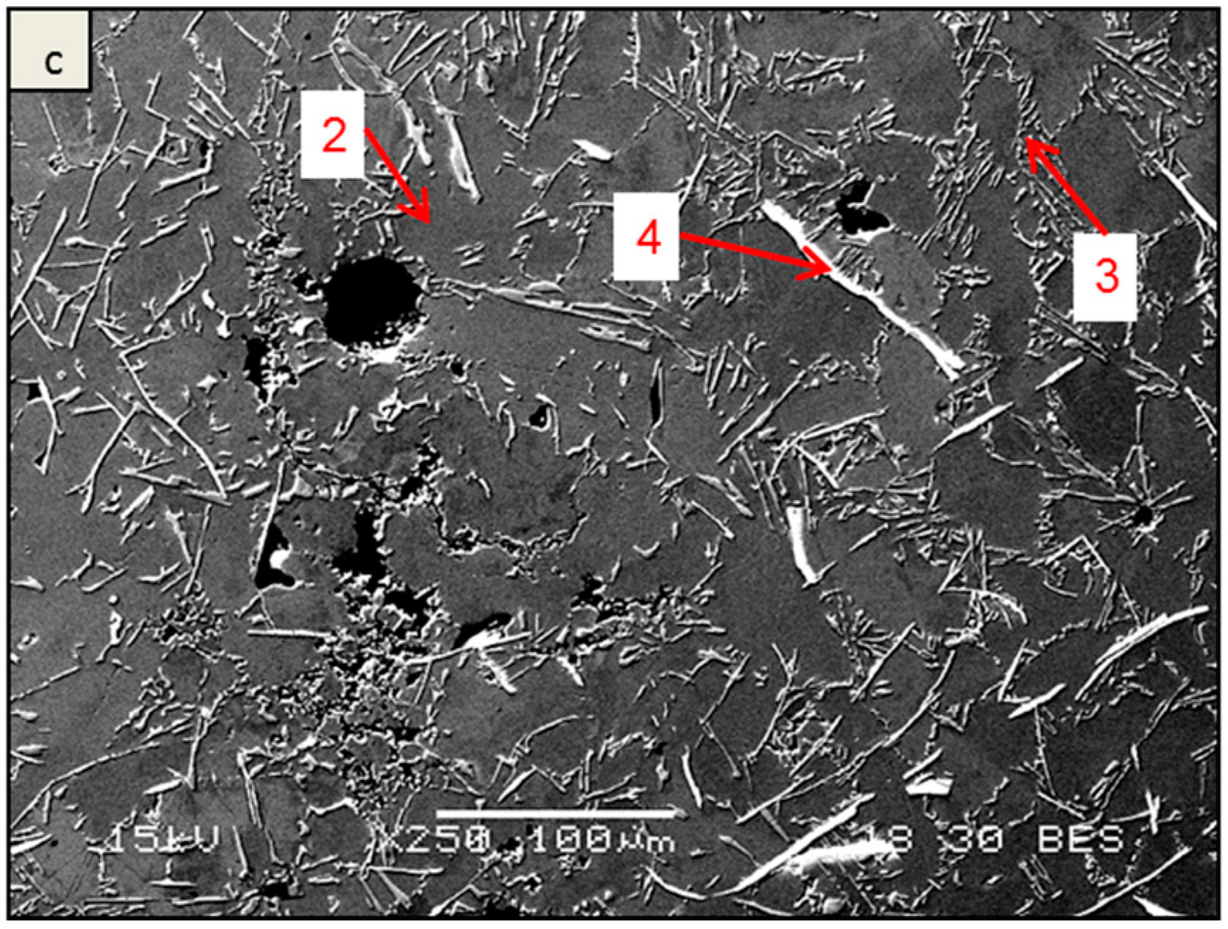
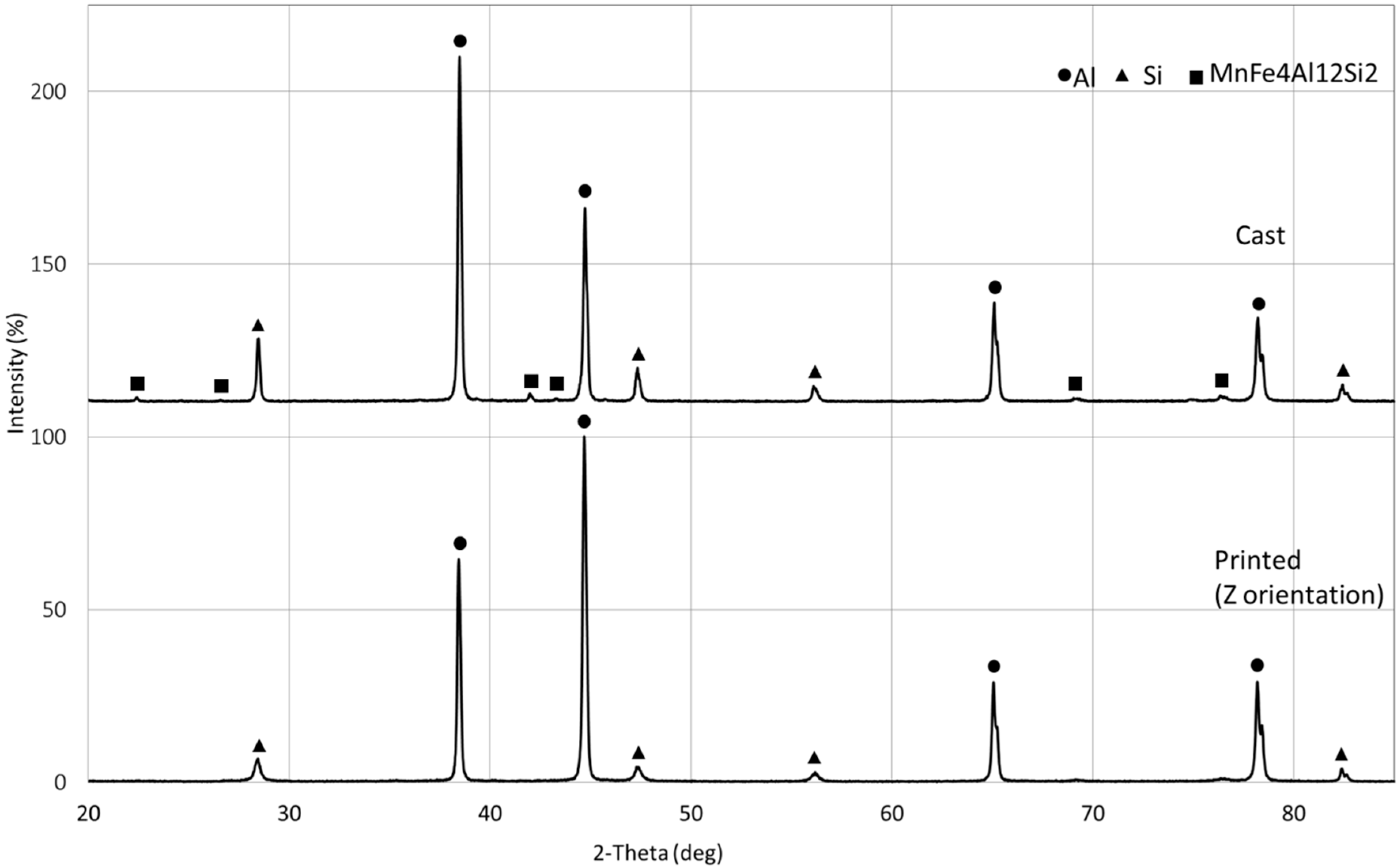
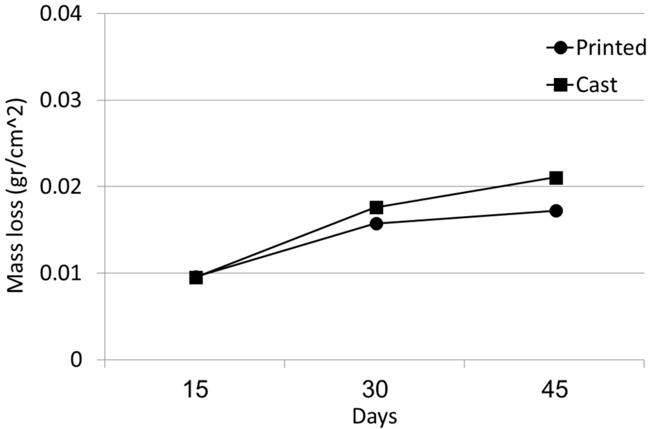
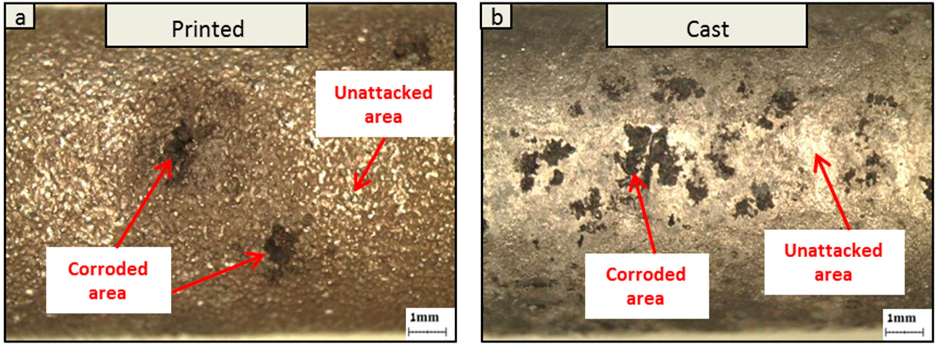
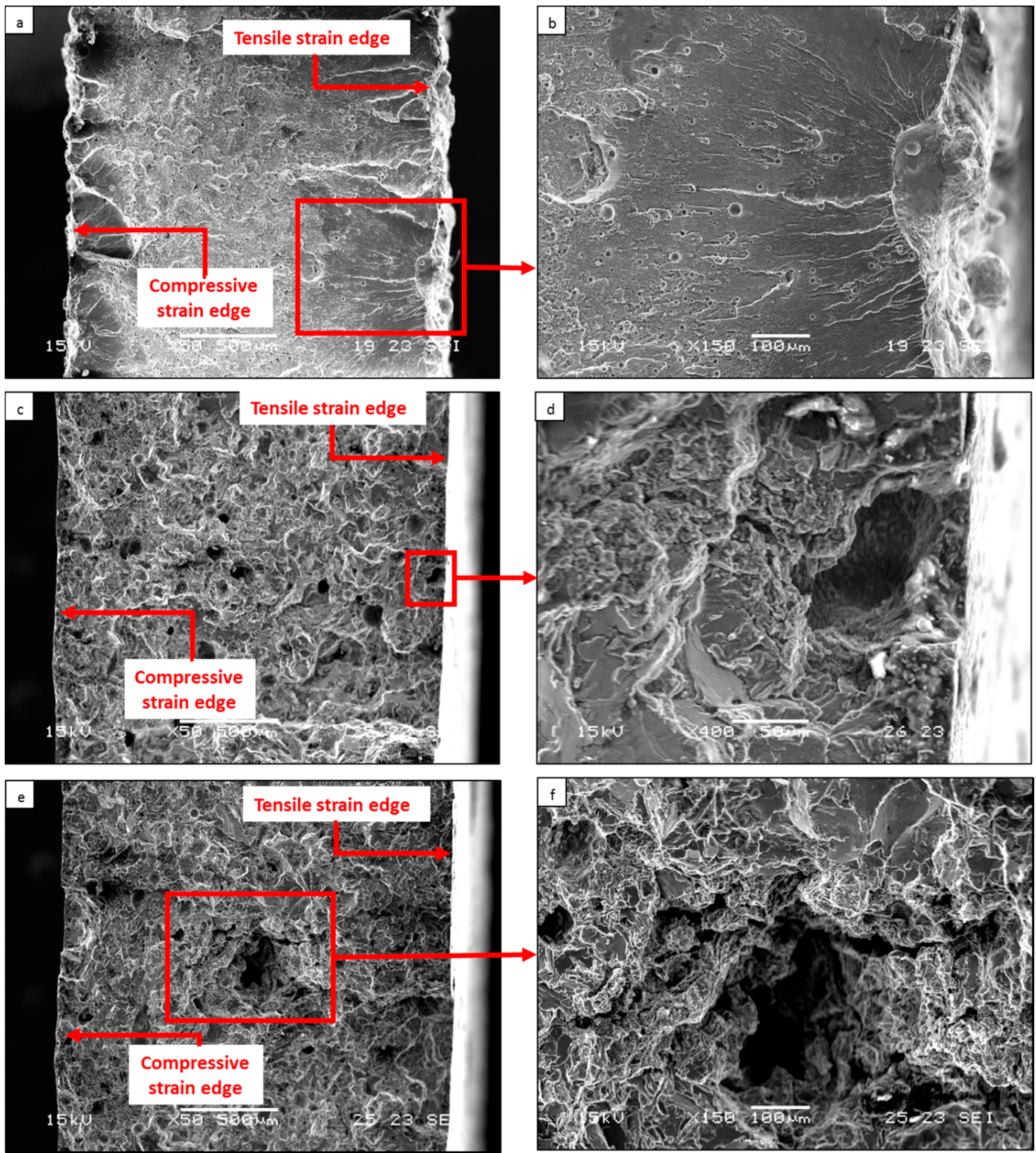
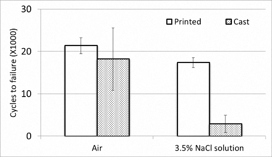
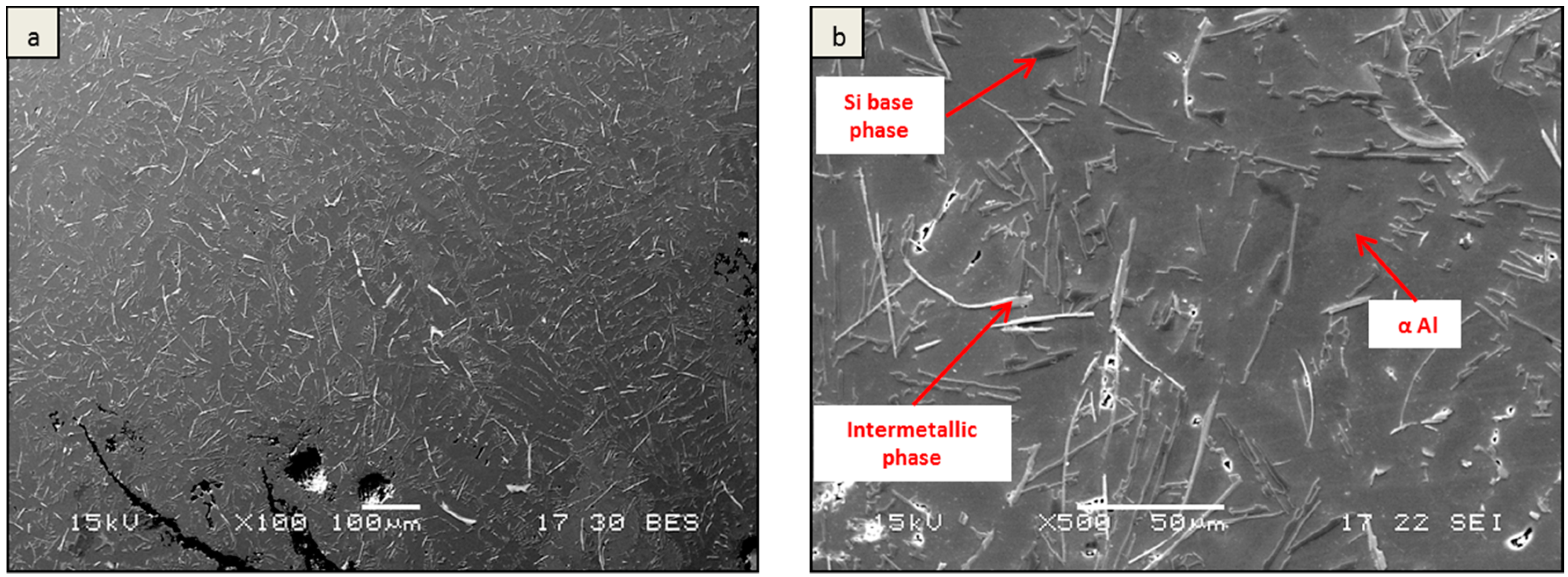
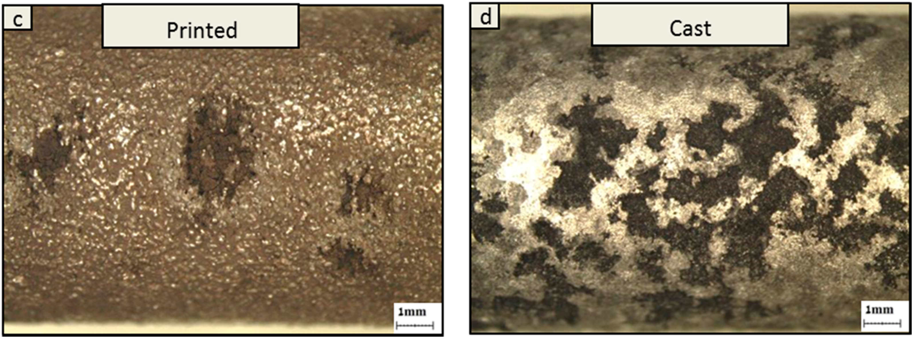
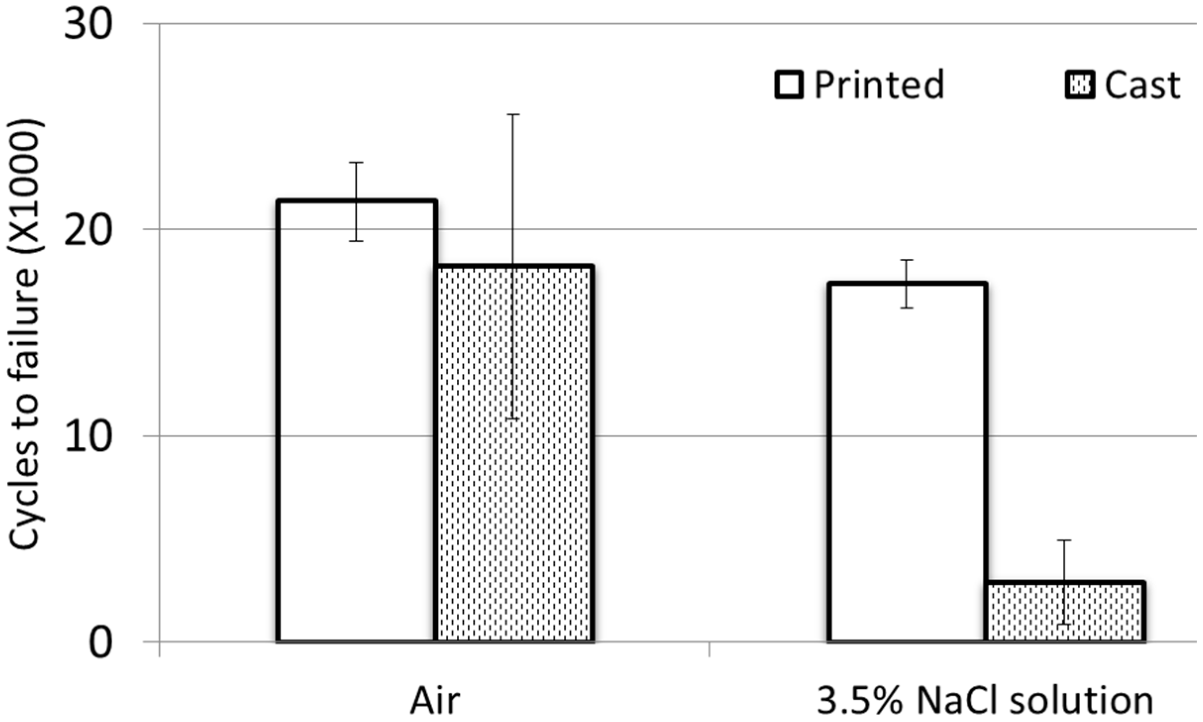
Printed specimens made from aluminum alloy AlSi10Mg were produced by an EOSINT M280 system using a selective laser melting (SLM) process with the following parameters: laser power 400 Watts, scanning speed 1000 mm/s, layer thickness 30 µm, and hatch spacing 0.2 mm. The shape of the printed specimens was either rectangular or cylindrical according to the designated tests. The printing orientation of the rectangular sample was ZX while that of the cylindrical bar was Z according to ISO/ASTM 52921-13 standard. The average grain size of the metal powder used for the printing process was about 50 µm and the protective gas atmosphere was pure argon. The printing procedure was followed by a stress relief heat treatment of 2 h at 300 °C. The counterpart Al alloy A360.2 was produced in ingot form by re-melting the alloy at 700 °C and gravity casting in a rectangular 6 × 12 × 5 cm iron die. All the test specimens produced from the cast alloy were machined from the central part of the ingot, which generates a relatively reduced surface roughness compared to the SLM sample. The very close similarity in the chemical compositions of the printed alloy and the gravity cast alloy are shown in Table 1, although it should be indicated that impurities concentration in the cast alloy was relatively higher.
Microstructure examination was carried out using optical and scanning electron microscopy (SEM) with a JEOL JSM-5600 (JEOL, Tokyo, Japan) equipped with EDS detector (Thermo Fisher scientific, Waltham, MA, USA) for spot chemical analysis. Identification of internal phases was conducted by X-ray diffractometer RIGAKU-2100H (RIGAKU, Tokyo, Japan) with Cu-Kα. The diffraction parameters were 40 KV/30 mA, and the scanning rate was 2°/min.
The corrosion behavior was examined by immersion test according to ASTM G31-12a standard and by electrochemical characterization in terms of potentiodynamic polarization analysis. All the corrosion tests were carried out in 3.5% NaCl solution with naturally dissolved oxygen in the electrolyte; the durations of immersion tests were up to 45 days. The pitting characterization was evaluated according to ASTM G46 standard. The potentiodynamic polarization analysis was carried out using a Bio-Logic SP-200 potentiostat equipped with Ec-Lab software V10.44 [10,11]. A standard three-electrode cell with a reference saturated calomel electrode (SCE) was used for this examination; the scanning rate was 0.5 mV/s. The low cycle corrosion fatigue (LCCF) tests in 3.5% NaCl solution were evaluated using a standard bending machine with a strain control apparatus [12]. The shape of the fatigue test specimen was rectangular with neck dimensions of 16 mm length, 8 mm width, and 2 mm thickness. The total length of the fatigue specimen was 80 mm and the radius of curvature at the neck area intersection was 15 mm. The low cycle fatigue test parameters included strain amplitude of 3% and frequency of 0.6 Hz. The bending stress direction in the printed alloy was perpendicular to the ZX printing orientation.

3. Results

Typical microstructures of cross-sections of printed and cast alloys are shown in Figure 1 and Figure 2, respectively, along with spot chemical analysis shown in Table 2. This has clearly revealed the relatively rapid solidification nature of the printed alloy during the SLM process compared to its counterpart cast alloy. The microstructure of the printed alloy was mainly composed of the Al matrix and a fine Si net with minor noticeable intermetallic precipitants. In addition, the selective porosity was mainly concentrated at the boundaries of the melt pool intersections. The relatively high manganese concentration in the SLM sample (shown in Table 2) can indicate that at least minor amounts of enriched Mn intermetallic precipitants were present in this sample, although it was difficult to identify them in the SEM microscopy analysis. The microstructure of the cast alloy was a regular dendritic structure with the eutectic phase of Si and precipitants enriched with Fe-Mn. The cast alloy also includes typical porosity defects that are inherently obtained during regular casting processes.
The X-ray diffraction analysis shown in Figure 3 supports the assumption that the amount of Fe-Mn precipitates with the formulation of MnFe4Al12Si2 was relatively increased in the cast alloy. The different intensities between the printed alloy compared to the cast alloy were related to the inherent epitaxial solidification nature of the printed alloy.
The corrosion resistance of printed and cast alloys in terms of corrosion rates as obtained by immersion tests in 3.5% NaCl solution are shown in Figure 4. This clearly indicates that the corrosion rate of the printed alloy was relatively reduced compared to that of the cast alloy after 30 and 45 days of exposure. Close-up views at the external surfaces of the two alloys after immersion times of 30 and 45 days are shown in Figure 5. While the localized corrosion attack in the printed alloy was relatively more scattered, the corrosion attack in the cast alloy was significantly more intensive, with overlapping of the initial corrosion sites and consequently increased corrosion products. In terms of pitting attack after 45 days of exposure, the pitting density (pits/cm2) in the printed alloy was 2.1 compared to 17.1 in the cast alloy; the pitting factor of the printed alloy was 6.3 compared to 3.4 in the cast alloy. This type of corrosion attack can be related to electrolytic stagnation that induces autocatalytic corrosion occurrence [13,14]; hence, since the mass loss was similar but the pit density of the printed alloy was much lower, the pits in the printed alloy must have been much larger. In addition, it was also apparent that the corrosion attack in the cast alloy had taken place preferably in the vicinity of the casting defects and close to the Fe-Mn enriched precipitates due to their microgalvanic effect [15,16,17,18]. In the printed alloy it could be seen that the corrosion attack tends to progress along the melt pool overlap that contains porosity as an inherent characteristic of the SLM process.
Electrochemical analysis of printed and cast alloys in terms of potentiodynamic polarization and Tafel extrapolation are shown in Figure 6 and Table 3, respectively. This revealed that the polarization curve of the cast alloy was relatively shifted to higher current densities, which indicates reduced corrosion resistance. This observation was also supported by the Tafel extrapolation measurements showing that the corrosion rate of the printed alloy was 0.23 mpy compared to 0.28 mpy in the cast alloy.
The life spans of printed and cast alloys obtained by low cycle corrosion fatigue in terms of the number of cycles to failure are shown in Figure 7. This indicates that the life span of the printed alloy was slightly larger than that of the cast alloy in air atmosphere and considerably larger in the corrosion environment of 3.5% NaCl solution. The correlated micrographs of the fracture surface obtained in 3.5% NaCl solution are shown in Figure 8. Relating to the printed alloy it can be seen that the cracking initiated from surface pitting and propagated across the sample creating a relatively smooth fracture surface before final snapping. In the case of the cast alloy it was evident that the cracking started from an irregular defect located very close to the surface area and the crack propagation across the sample was mainly along the casting defects [19,20].

4. Discussion

The results obtained by the present study in terms of immersion tests and potentiodynamic polarization analysis indicate that the corrosion resistance of the printed and cast alloys was relatively similar, with a slight advantage to the printed alloy. This was manifested by the fact that the mass loss was slightly lower for the printed alloy after 45 days of exposure, but the pits were deeper. The relatively reduced mass loss of the printed alloy can be mainly attributed to the differences between the microstructure characteristics of those two alloys. According to this understanding, the relatively reduced corrosion resistance of the cast alloy can be explained by several reasons, including: (i) the presence of inherent casting defects mainly in the form of irregular porosity; (ii) the relatively intensive formation of enriched Fe and Mn precipitates (MnFe4Al12Si2) that have a detrimental microgalvanic effect; (iii) the dendritic microstructure with a secondary eutectic phase that limits the dissolution capability and homogeneity of the alloy. On the other hand, the relative improved corrosion resistance of the printed alloy can be attributed mainly to the increased solidification rate obtained by the SLM process. This has resulted in gaining a much more homogenous microstructure with improved dissolution of alloying elements and impurities with nearly no precipitates. Altogether this microstructure is known to have a beneficial effect on the corrosion resistance [21]. The detrimental effect of the selective porosity present at the boundaries of the melt pool overlap was relatively minor, although it was evident that the corrosion attack tends to progress along those areas.
The significant improvement in the life span of printed alloy compared to cast alloy obtained under LCCF in 3.5% NaCl solution is mainly related to the differences between the microstructure characteristics of the two alloys. This is based on the fact that the test duration of the LCCF was less than half a day and, hence, the LCCF test results cannot be correlated with the small differences in mass loss obtained after 45 days of immersion, as shown in Figure 4. The relatively reduced life span of the printed alloy may be related to the fact that the crack initiation and propagation in this alloy was mainly along typical casting defects such as irregular porosity, as shown by the fracture surface analysis in Figure 8c–f. According to this understanding, it is believed that the crack propagation in the cast alloy was relatively accelerated compared to that of the printed alloy. The accelerated crack propagation rate in the cast alloy can be attributed to the synergistic effect between the corrosive environments and the internal concentration stresses created by the irregular gravity casting defects.

5. Conclusions

The very slight improvement in the corrosion resistance of printed alloy AlSi10Mg obtained by the SLM process vs. its counterpart gravity cast alloy was mainly related to their differences in terms of microstructure and defect characteristics. Those differences were mainly generated due to the relatively higher solidification rate experienced by the printed alloy during the SLM process. The increased solidification rate creates a much more homogenous microstructure with minor amounts of precipitates and relatively reduced casting defects, which consequently slightly improve the corrosion performance, mainly in terms of mass loss.
The comparatively enhanced life span of the printed alloy obtained after LCCF is mainly attributed to the differences between the microstructure characteristics of the two alloys. It is believed that the accelerated cracking in the cast alloy was generated due to the synergistic effect between the corrosive environment and the stress concentration created by gravity casting defects such as irregular porosity.

Acknowledgments

The authors would like to thank Sharon Tuvia Ltd. for the preparation of 3D printed specimens by the SLM process, and A. Kafri, A. Zakay, and R. Schwartz from Ben-Gurion University for their assistance in the experimental activities.

Author Contributions

Eli Aghion and Avi Leon conceived and designed the experiments; Avi Leon performed the experiments; Eli Aghion, Avi Leon and Amnon Shirizly analyzed the data; Eli Aghion and Avi Leon wrote the paper.

Conflicts of Interest

The authors declare no conflict of interest.

References

  1. Gao, W.; Zhang, Y.; Ramanujan, D.; Ramani, K.; Chen, Y.; Williams, C.B.; Wang, C.C.L.; Shin, Y.C.; Zhang, S.; Zavattieri, P.D. The status, challenges, and future of additive manufacturing in engineering. Comput. Aided Des. 2015, 69, 65–89. [Google Scholar] [CrossRef]
  2. Manfredi, D.; Calignano, F.; Krishnan, M.; Canali, R.; Ambrosio, E.P.; Biamino, S.; Ugues, D.; Pavese, M.; Fino, P. Additive Manufacturing of Al Alloys and Aluminium Matrix Composites (AMCs). Light Metal Alloy. Appl. InTech 2014. [Google Scholar] [CrossRef]
  3. Kempen, L.; Thijs, L.; van Humbeeck, J.; Kruth, J.P. Mechanical properties of AlSi10Mg produced by Selective Laser Melting. Phys. Procedia 2012, 39, 439–446. [Google Scholar] [CrossRef]
  4. Wang, F. Mechanical property study on rapid additive layer manufacture Hastelloy X alloy by selective laser melting technology. Int. J. Adv. Manuf. Technol. 2012, 58, 545–551. [Google Scholar] [CrossRef]
  5. Santos, M.C., Jr.; Machado, A.R.; Sales, W.F.; Barrozo, M.A.S.; Ezugwu, M.O. Machining of aluminum alloys: A review. Int. J. Adv. Manuf. Technol. 2016. [Google Scholar] [CrossRef]
  6. Calignano, F.; Manfredi, D.; Ambrosio, E.P.; Iuliano, L.; Fino, P. Influence of process parameters on surface roughness of aluminum parts produced by DMLS. Int. J. Adv. Manuf. Technol. 2013, 67, 2743–2751. [Google Scholar] [CrossRef]
  7. Rajamure, R.S.; Vora, H.D.; Srinivasan, S.G.; Dahotre, N.B. Laser alloyed Al-W coatings on aluminum for enhanced corrosion resistance. Appl. Surf. Sci. 2015, 328, 205–214. [Google Scholar] [CrossRef]
  8. Zaid, B.; Saidi, D.; Benzaid, A.; Hadji, S. Effects of pH and chloride concentration on pitting corrosion of AA6061aluminum alloy. Corros. Sci. 2008, 50, 1841–1847. [Google Scholar] [CrossRef]
  9. Fulcher, B.A.; Leigh, D.K.; Watt, T.J. Comparison of AlSi10Mg and Al 6061 processed through DMLS. In Proceedings of the Solid Freeform Fabrication (SFF) Symposium, Austin, TX, USA, 4–6 August 2014.
  10. Levy, G.; Aghion, E. Effect of diffusion coating of Nd on the corrosion resistance of biodegradable Mg implants in simulated physiological electrolyte. Acta Biomater. 2013, 9, 8624–8630. [Google Scholar] [CrossRef] [PubMed]
  11. Aghion, E.; Levy, G. The effect of Ca on the in vitro corrosion performance of biodegradable Mg-Nd-Y-Zr alloy. J. Mater. Sci. 2010, 45, 3096–3101. [Google Scholar] [CrossRef]
  12. Unigovski, Y.B.; Lothongkum, G.; Gutman, E.M.; Alush, D.; Cohen, R. Low-cycle fatigue behavior of 316L-type stainless steel in chloride solutions. Corros. Sci. 2009, 51, 3014–3020. [Google Scholar] [CrossRef]
  13. Itzhak, D.; Aghion, E. An anodic behavior study of an analogical sintered system of austenitic stainless steel in H2SO4 solution. Corros. Sci. 1984, 24, 145–152. [Google Scholar] [CrossRef]
  14. Itzhak, D.; Aghion, E. Corrosion behavior of hot pressed austenitic stainless steel in H2SO4 solutions at room temperature. Corros. Sci. 1983, 23, 1085–1094. [Google Scholar] [CrossRef]
  15. Mingo, B.; Arrabal, R.; Pardo, A.; Matykina, E.; Skeldon, P. 3D study of intermetallics and their effect on the corrosion morphology of rheocast aluminium alloy. Mater. Charact. 2016, 112, 122–128. [Google Scholar] [CrossRef]
  16. Arrabal, R.; Mingo, B.; Pardo, A.; Mohedano, M.; Matykina, E.; Rodríguez, I. Pitting corrosion of rheocast A356 aluminium alloy in 3.5 wt. % NaCl solution. Corros. Sci. 2013, 73, 342–355. [Google Scholar] [CrossRef]
  17. Szklarska-Smialowska, Z. Pitting corrosion of aluminum. Corros. Sci. 1999, 41, 1743–1767. [Google Scholar] [CrossRef]
  18. Birbilis, N.; Buchheit, R.G. Electrochemical characteristics of intermetallic phases in aluminum alloys. J. Electrochem. Soc. 2005, 152, 140–151. [Google Scholar] [CrossRef]
  19. Bronfin, B.; Aghion, E.; von Buch, F.; Schumann, S.; Katsir, M. Die casting magnesium alloys for elevated temperature applications. In Magnesium Technology 2001; Hryn, J.N., Ed.; Wiley & Sons, Inc.: Hoboken, NJ, USA, 2001; pp. 127–130. [Google Scholar] [CrossRef]
  20. Aghion, E.; Gueta, Y.; Moscovitch, N.; Bronfin, B. Effect of yttrium additions on the properties of grain-refined Mg-3%Nd alloy. J. Mater. Sci. 2008, 43, 4870–4875. [Google Scholar] [CrossRef]
  21. Hakimi, O.; Aghion, E.; Goldman, J. Improved stress corrosion cracking resistance of a novel biodegradable EW62 Mg alloy by rapid solidification, in simulated electrolytes. Mater. Sci. Eng. 2015, 51, 226–232. [Google Scholar] [CrossRef] [PubMed]
Figure 1. (a) Microstructure of printed alloy: (b) longitudinal cross-section (side view: printing direction—Z); (c) transverse cross-section (top view: printing direction—XY).
Metals 06 00148 g001
Figure 2. (a) Microstructure of cast alloy on cross-section: (b) longitudinal and (c) transverse.
Metals 06 00148 g002aMetals 06 00148 g002b
Figure 3. X-ray diffraction analysis of printed and cast alloys.
Metals 06 00148 g003
Figure 4. Corrosion rates of printed and cast alloys after immersion tests in 3.5% NaCl solution.
Metals 06 00148 g004
Figure 5. Optical microscopy showing corrosion attack at the surface of printed and cast alloys after immersion tests in 3.5% NaCl solution: (a,b) after an exposure time of 30 days; (c,d) after an exposure time of 45 days.
Metals 06 00148 g005aMetals 06 00148 g005b
Figure 6. Potentiodynamic polarization curves obtained in 3.5% NaCl solution.
Metals 06 00148 g006
Figure 7. Number of cycles to failure after LCCF in 3.5% NaCl solution.
Metals 06 00148 g007
Figure 8. Micrographs of fracture surface obtained after LCCF in 3.5% NaCl solution. (a,b) Printed alloy; (cf) cast alloy.
Metals 06 00148 g008
Table 1. Chemical compositions of laser-printed and gravity cast alloys obtained by mass spectrometer.
Wt. %SiMgFeMnTiZnCuNiPbSnAl
Alloy
Printed10.550.2680.2270.0040.0090.0070.0040.006<0.001<0.001Bal.
Cast10.510.2670.7670.1340.080.0840.1240.0120.0160.004Bal.
Table 2. SEM-EDS spot chemical analysis of printed and cast alloys (locations shown in Figure 1b and Figure 2c).
Element (wt. %)MnFeMgSiAl
Tested area
Printed - 11.55 ± 0.070.2 ± 0.040.33 ± 0.0110.56 ± 0.0587.35 ± 0.31
Cast - 21.78 ± 0.0700.1 ± 0.011.04 ± 0.0896.99 ± 0.35
Cast - 31.63 ± 0.060.07 ± 0.030.14 ± 0.0137.91 ± 0.1360.25 ± 0.22
Cast - 43.81 ± 0.0921.77 ± 0.140.15 ± 0.0221.29 ± 0.0852.99 ± 0.19
Table 3. Corrosion measurements obtained from polarization curves and Tafel extrapolation.
ParameterEcorr (V)Icorr (µA/cm2)C.R (mpy)
Specimen
Printed−0.730.540.23
Cast−0.720.640.28

