Article

Metal Injection Molding (MIM) of Magnesium and Its Alloys

1
Helmholtz-Zentrum Geesthacht, Centre for Materials and Coastal Research, Institute of Materials Research, Division Metallic Biomaterials, Max-Planck Straße 1, Geesthacht D-21502, Germany
2
Maschinenbau, Verfahrenstechnik und Maritime Technologien, University of Applied Sciences, Hochschule Flensburg, Kanzleistraße 91-93, Flensburg D-24943, Germany
3
Fakultät für Maschinenbau, Helmut Schmidt University, Holstenhofweg 85, Hamburg D-22043, Germany
*
Author to whom correspondence should be addressed.
Metals 2016, 6(5), 118; https://doi.org/10.3390/met6050118
Submission received: 24 March 2016 / Revised: 12 May 2016 / Accepted: 13 May 2016 / Published: 20 May 2016
(This article belongs to the Special Issue Metal Injection Moulding)

Abstract

:
Current research has highlighted that magnesium and its alloys as biodegradable material are highly suitable for biomedical applications. The new material fully degrades into nontoxic elements and offers material properties matching those of human bone tissue. As biomedical implants are rather small and complex in shape, the metal injection molding (MIM) technique seems to be well suited for the near net shape mass production of such parts. Furthermore, MIM of Mg-alloys is of high interest in further technical fields. This study focusses on the performance of MIM-processing of magnesium alloy powders. It includes Mg-specific development of powder blending, feedstock preparation, injection molding, solvent and thermal debinding and final sintering. Even though Mg is a highly oxygen-affine material forming a stable oxide layer on each particle surface, the material can be sintered to nearly dense parts, providing mechanical properties matching those of as cast material. An ultimate tensile strength of 142 MPa, yield strength of 67 MPa, elastic modulus of 40 GPa and 8% elongation at fracture could be achieved using novel organic polymer binders for the feedstock preparation. Thus, first implant demonstrator parts could be successfully produced by the MIM technique.

Graphical Abstract

1. Introduction

Powder metallurgy (PM) of magnesium and its alloys offers three major advantages in comparison to conventional primary shaping techniques from the liquid state and metal forming techniques from the solid state:
  • PM processing of Mg facilitates homogeneous distribution of elements.
  • PM allows us to obtain a fine-grained microstructure. The low grain size of the magnesium alloy metal powder can be kept or even reduced to the sub-micrometer scale using PM metal forming techniques, e.g., extrusion or equal channel angular pressing (ECAP) [1,2,3]. However, these techniques are suitable for the production of bar stock and semi-finished products only.
  • Difficulties occurring during metal forming, which are due to the hexagonal lattice structure of magnesium, can be avoided by using PM-techniques. In particular, near net shape techniques like powder pressing and sintering of Mg [4], powder forging or metal injection molding (MIM) of Mg [5,6] can be applied.
MIM of Mg, in particular, seems to be very attractive since Mg alloys were identified as being a highly suitable biodegradable orthopedic implant material for biomedical applications [7,8,9,10,11,12,13,14,15,16,17]. MIM of Mg alloys can be used for the industrial economic near net shape mass production of such complex-shaped implants at high reproducibility in large numbers.
However, sintering of Mg and, beyond that, MIM of Mg is still not a standardized process. In the literature, sintering of Mg had been reported to be unfeasible for many years because the stable oxide layer of Mg acts as diffusion barrier for the essential diffusion process during sintering [18]. Thereafter, a lot of work was carried out in order to understand the sintering performance of Mg and to develop the processing of sintering Mg [19,20,21]. The main challenges of sintering the highly oxygen-affine metal are the prevention of any additional oxygen pick up on the one hand and the prevention of any reactions between Mg and polymer binder or thermal debinding products on the other hand. In [19,20,21] small amounts of Ca could be highlighted as a considerable sintering aid by forming a liquid phase and weakening the oxide layer of the Mg particles, and an addition of 0.9 wt. % Ca proved to be optimal in terms of mechanical properties. Therefore, in this work an Mg-0.9Ca alloy is used. Moreover, the polymer binder must provide good rheological behavior to fulfil the requirements for a failure free green part production during the injection molding step. Hence, the choice of suitable polymer binder components is limited and will be discussed in this study. Therefore, the impact of several organic polymer binders such as polybuthene (PB), polypropylene (PP), polypropylene copolymer polybutene (PPcoPB) and polypropylene copolymer polyethylene (PPcoPE) on the mold filling quality during injection molding and on the sintering ability of Mg is within the scope of this study.
MIM of Mg-0.9Ca alloy was performed very successfully with different materials and testing specimens. More complex demonstrator parts as shown in Figure 1a and biodegradable bone screw demonstrators as shown in Figure 1b could be manufactured, too.
Another aspect of MIM of Mg alloys is illustrated in Figure 1b. Recently, in clinical usage, biodegradable implants have been made of poly L-lactide/DL-lactide copolymers (PLDLA) which suffer from low mechanical strength and stiffness as well as from acidulous degradation behavior (see Figure 1b, upper screw) and, thus, an increased inflammatory risk after implantation. These PLDLA copolymer screws are made by injection molding technique as well. Hence, the polymer based screws can be substituted by MIM-Mg-based screws using the same injection molding technique and the same mold, as shown in Figure 1b.
In this paper, an overview on the challenges and recent success of MIM of Mg is given, focusing on the role of binder on the sintering behavior.

2. Materials and Methods

2.1. Powder and Feedstock (or Feedstockpreparation)

Pure spherical and commercially available gas atomized Mg-powder was used as base material (SFM, Martigny, Switzerland). A spherical gas atomized Mg-10Ca powder (ZfW, Clausthal, Germany) was used as master alloy powder (MAP) to prepare Mg-0.9Ca powder blends by mixing the two components. Paraffin wax components, stearic acid and several organic polymer binder components as shown in Table 1 were used to prepare the feedstock for the injection molding process. Polymer content was varied between 5 and 35 m. % of the binder system. The powder loading was 64 vol. % for all feedstock batches. The two powder components and the organic binder components were placed in a mixing cup, preheated up to 160 °C and mixed in a planetary mixer by stirring the components for five minutes applying maximum rotation speed of 2000 rpm (Thinky ARE 250 planetary mixer, Tokyo, Japan). The homogeneity of the batch was checked by stirring the feedstock with a spittle. The described process can be iterated until homogeneity of the feedstock is adequate. To avoid any oxygen uptake of the magnesium powder components, the materials were handled in protective argon atmosphere in a glovebox system (Unilab, MBraun, Garching, Germany).

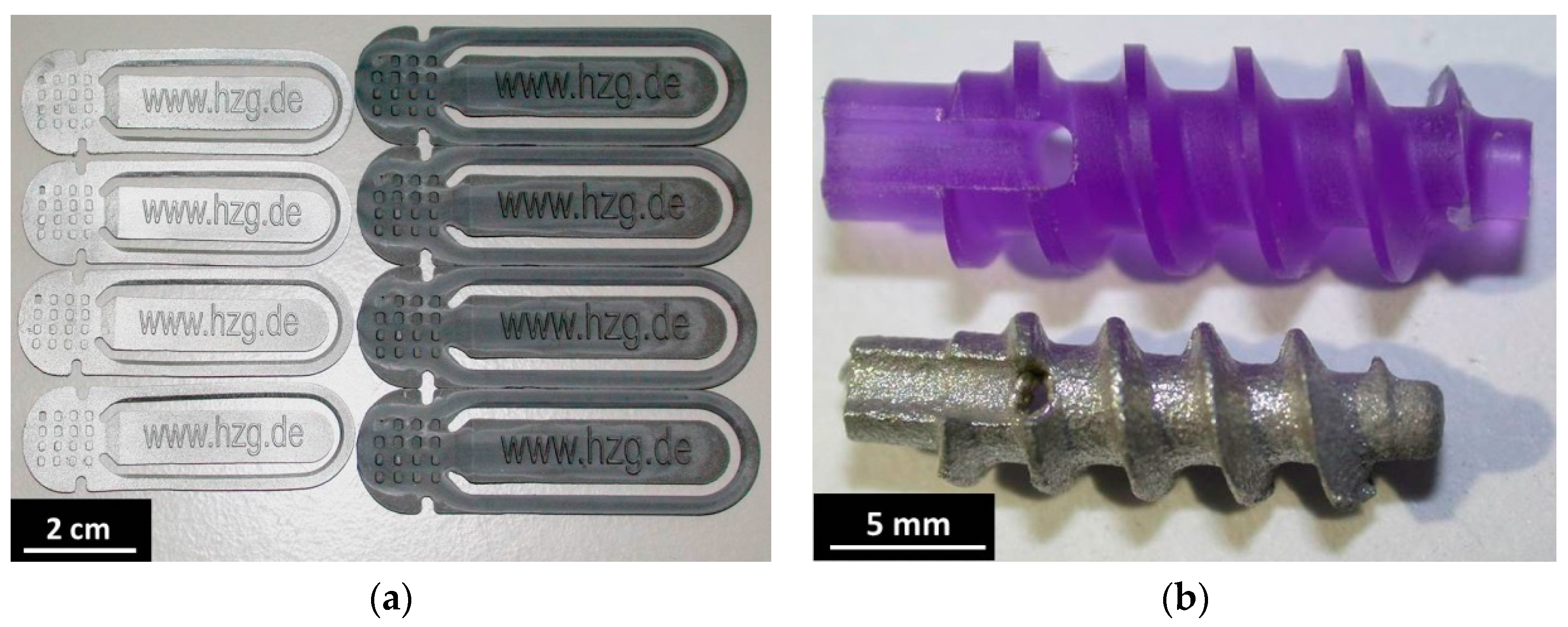
2.2. Metal Injection Moulding (MIM)

Injection molding of the feedstock was carried out by using an industrial injection molding machine (320S Allrounder, Arburg, Loßburg, Germany). Rectangular test specimens (l = 43.4 mm, w = 5.4 mm, h = 2.9 mm), cylindrical rods (d = 4.5 mm, l = 30 mm), dogbone-shape tensile test specimens consistent to ISO 2740 and different demonstrator parts (bookmarks) as well as medical bone screw implant demonstrators as shown in Figure 1a,b were manufactured.

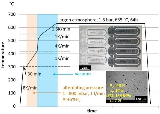
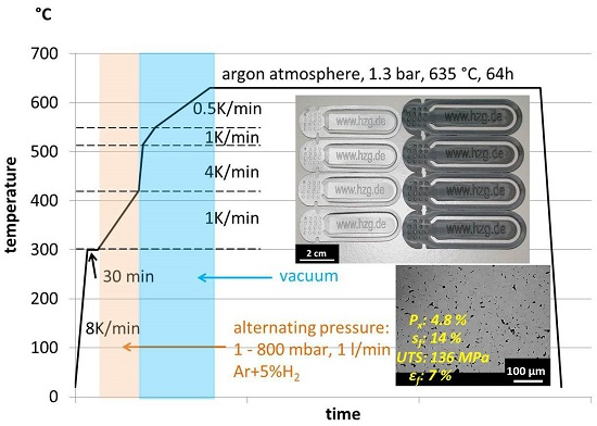
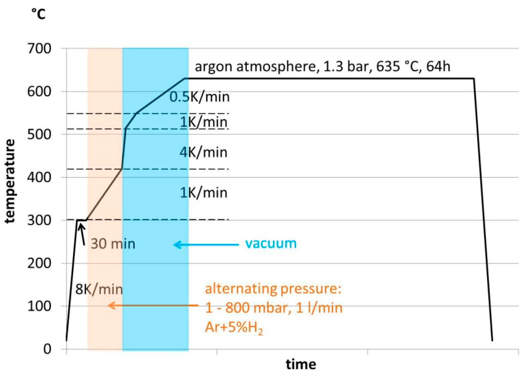
2.3. Debinding and Sintering

Chemical debinding of the paraffin wax components and the stearic acid was carried out in a hexane bath at 45 °C for 10 to 15 h by using an automatic solvent debinding device (EBA50/2006, Lömi, Großostheim, Germany). Thermal debinding and sintering was performed in a combined debinding and sintering hot wall tube furnace with integrated binder precipitation zone (XRetort, Xerion, Freiberg, Germany).
Thermal debinding was performed according to the diagram in Figure 2. After having taken several preparatory steps like furnace evacuation and purging, gas tube purging and leakage check, the furnace was quickly heated up to 300 °C at 800 mbar, using high purity argon (Ar 6.0) to enable fast warming of the specimen. The thermal debinding took place in reactive Ar + 5% H2 (Arcal 15, Air Liquide, Düsseldorf, Germany) using alternating atmosphere pressure between 1 to 800 mbar at 1 L/min gas flow to reduce reactive binder monomers that may occur. Since Mg has the highest vapor pressure of all technical metals (231.5 Pa at 627 °C [22]), it cannot be sintered under vacuum condition. Sintering under vacuum condition would result in evaporation of the material and related deposition in the colder binder precipitation area of the furnace. However, debinding under vacuum conditions is essential for obtaining satisfying residual-free thermal debinding. Hence, the heating phase after thermal debinding was performed under vacuum condition (<1 × 10⁻¹ mbar) up to sintering temperature, before switching to argon atmosphere for long-time sintering. Investigations concerning the sintering time and temperature were performed in earlier works [4,5,6].
Sintering was conducted for 64 h at 635 °C furnace temperature in Ar 6.0 atmosphere. As each spherical Mg particle is leaguered by a thin oxide layer which strongly inhibits the diffusion between neighbored Mg-particles, this long sintering time is required to destabilize the oxide layer [4].

2.4. Characterisation Methods

The rectangular bars and cylindrical rods were used for the non-destructive measurement of the dynamic elastic modulus Edyn., applying resonance sonic spectroscopy according to EN-ISO 12680-1 and ASTM E1875-08 (RFDA, IMCE, Genk, Belgium). The residual porosity Px and the shrinkage sf of the sintered rectangular bars and cylinders were determined using the Archimedes method (Sartorius-LA230S, Sartorius, Göttingen, Germany) and geometrical data assessment (Mahr-16EX, calliper, Mahr, Göttingen, Germany).
P x = 1 Archimedes density theoretical density
s f = 1 sintered length green length
The tensile tests of sintered MIM Mg-0.9Ca dogbone-shape test specimen were performed according to DIN EN ISO 6892-1:2009 B on a materials testing machine (RM100, Schenck Trebel, Darmstadt, Germany). The microstructure was observed by using micro-tomography (Y.Cougar, Yxylon, Hamburg, Germany) and a scanning electron microscopy (SEM) (Zeiss-DSM 962, Zeiss, Jena, Germany and Phenom-Pro X, Phenom-World, Eindhoven, The Netherlands). For microstructural analysis samples were cut, embedded, ground and polished.

3. Results and Discussion

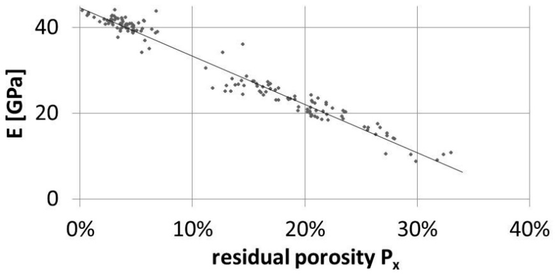
3.1. Young’s Modulus vs. Residual Porosity Relationship

Figure 3 shows the correlation between the Young’s modulus of the sintered MIM part and its residual porosity Px. The typical linear dependency of the Young’s modulus from total residual porosity is displayed, which is often shown in literature for PM-materials [23]. However, the linear trend line fit shown in Figure 3 displays that the Young’s modulus will become zero when approaching approximately 40% of residual porosity. This is typical for spherical PM-materials because a total porosity above 40% would result in no contact between the powder particles and hence, zero Young’s modulus. Achievement of higher porosity has been rendered possible by using PM-methods in addition to space holder technique [24] or metal powder feedstock infiltration technique [25]. The correlation of the Young’s modulus to residual porosity of these highly porous cancellous structures may theoretically show zero Young’s modulus when approaching 100% of porosity and a near-polynomic-2nd or a near-exponential trend line character. However, the lack of survey points in the higher porous region of the curve and the aforementioned general limitations in sintering fine powders to ultra-high porous compacts allow an earlier intersection of the curve with the x-axis and linear curve character. The extrapolation of the linear graph onto the axis of ordinates displays that MIM Mg-0.9Ca material would show an elastic modulus of approximately 44.6 GPa in fully dense conditions. This is identical to the elastic modulus of conventionally permanent mold direct chill cast Mg-0.9Ca material [22].

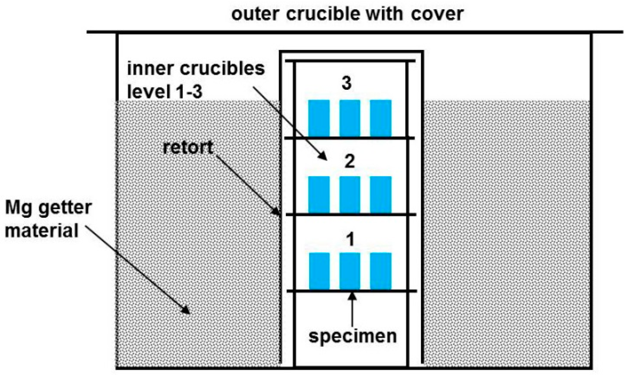
3.2. Furnace and Crucible Requirements

As mentioned in earlier works, sintering of Mg requires a special labyrinth like crucible configuration and the use of Mg getter material (particle size 0.06–0.3 mm purity >98.5% Merck, Darmstadt, Germany) inside of this crucible setup [19]. In this setup, three levels of specimen were placed inside of the inner crucible and a lose fill of Mg getter was placed in the outer crucible as shown in Figure 4.
Magnesium has the highest intrinsic vapor pressure of all constructional metals [22]. After thermal debinding, the furnace was heated up under vacuum condition (see Figure 2, blue area). In this process step, Mg getter material partly evaporated, forming a highly oxygen-affine and specimen-protecting Mg-vapor atmosphere inside of the crucible setup. However, the used retort furnace (XRetort, Xerion, Freiberg, Germany) was heater controlled and holds only two heating zones. Hence, the temperature deviation inside of the crucible was ±12 K. This gradient results in different sintering temperature depending on the positioning inside of the crucible and hence, different specimen temperature. As a consequence, resublimation of Mg-vapor on the surfaces of specimens holding the lowest temperature on the upper level 3 could be observed, as shown in Figure 5.
In order to avoid these phenomena, future work will be done using a furnace specified for the sintering of Mg, restricting temperature deviation to ±1 K (, RRO350/900, MUT Advanced Heating, Jena, Germany).

3.3. Feedstock and Recycling Requirements

As mentioned in the previous chapters, MIM processing involves the possibility of high materials utilization rate due to the potential of nearly 100% usage of the feedstock. In the framework of this study, a pelletizing machine was used for the granulation and recycling of feedstock sprue and green parts. Even though the device was accurately cleaned after change of the feedstock material, e.g., from titanium to magnesium, residuals of titanium could still be detected in the microstructure of the sintered Mg-component by using non-destructive X-ray microtomography method, as shown in Figure 6, and SEM, as shown in Figure 7 (see bright single particles and blue markers). This phenomenon will be avoided in future work by using separate pelletizing machines for magnesium and titanium, and separate injection molding units.

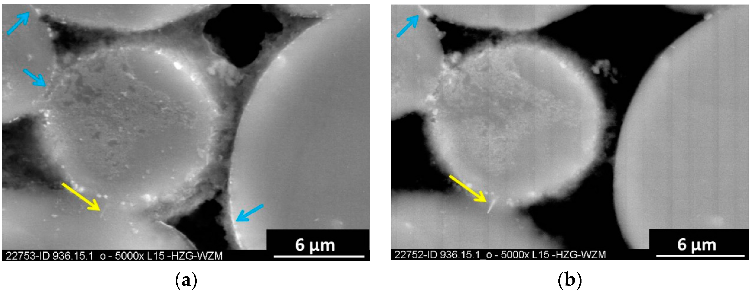
3.4. Organic Polymer Binder Requirements

For MIM of highly reactive metals like titanium or magnesium, two major requirements have to be fulfilled by the polymer binder system:
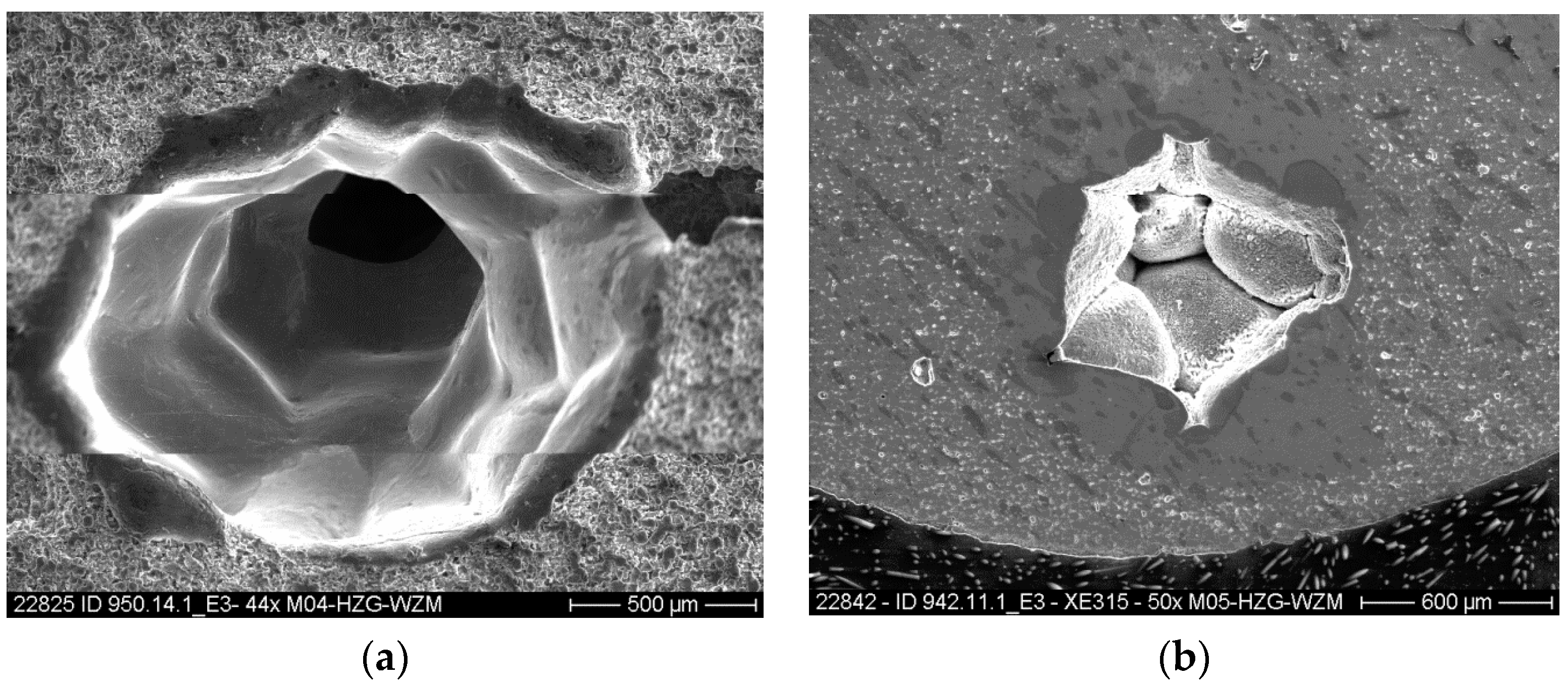
  • The binder system has to possess a perfect rheological behavior to enable failure-free injection molding of the feedstock. Hence, no jetting blistering or cavity formation in the green compact is acceptable.
  • The binder or its thermal debinding products shall not harm the sintering performance of the magnesium powder compact.
For several years, PE-VA has been successfully used for MIM of titanium at Helmholtz-Zentrum Geesthacht (HZG) [26]. The use of this binder component results in satisfying rheological behavior during injection molding and reasonable sintering performance. Hence, both requirements mentioned before are given. Therefore, at the beginning of MIM of Mg the use of PE-VA was reasonable. As a result, the first requirement of perfect injection molding performance could be met successfully [27]. However, the use of PE-VA results in a major inhibition of the sintering performance of Mg alloys. The use of a binder system containing 35 wt. % of PE-VA results in an UTS of only 6 MPa at 33% of residual porosity as shown in Figure 7a.
In contrast, different polymer binder components, such as PP, PB or PPcoPB, met the second requirement but failed at the first requirement [5]. The main difference of PE-VA in comparison to PP, PB or PPcoPB is the oxygen containing acetate group in the molecular chain of the PE-VA. This acetate group might be the reason for the poor sintering performance of PE-VA due to its interaction with the Mg material. However, the use of pure polyethylene binder (PE) results in a poor sintering performance, too [28]. There are two assumptions for this:
  • PE contains quite different and more Mg-affine production residue than PP or PB.
  • PE degrades in more Mg-affine olefins than PP or PB do.
With regard to the second assumption, the formation of Mg-carbonate and at higher temperature metastable Mg or Ca carbides on the Mg-particle surfaces may be the reason for the poor sintering performance of PE based polymers. The micrographs in Figure 8a,b give an idea of the formation of presently unknown phases in the system magnesium-calcium-polyethylene at sintering conditions. The formation of Mg2C3 might be possible, but it cannot be observed after sintering using conventional metallographic specimen preparation due to its metastable character and its high affinity to air humidity and water, respectively. However, the needle shape crystal, as shown in Figure 8, seems to be positioned slightly underneath the polished surface and, hence, it was protected from water used for the metallographic preparation, this structure maybe belongs to a carbide with the structure Mg2C3. However, this issue is currently under investigation.
The malfunction of PP, PB or PPcoPB with regard to the first requirement can be explained by the slight miscibility of the polymer components with the paraffin wax components. Hence, segregation of liquid wax from the semi-solid backbone polymer component during injection molding was observed, resulting in jetting, blistering and cavity formation in the green compact as well as in dosing problems, feedstock afflux and non-return valve damage in the injection molding machine. Yellow arrows on the micro-tomography of Figure 6 display dense areas of the inner microstructure. These areas were generated through jetting during green part production. The jetting cavity was then partly or fully filled with magnesium during sintering treatment through sublimation and resublimation or due to an exuding liquid phase of Mg-material in the inner of the compact. This effect can be seen in more detail in Figure A1a,b and Figure A2a,b. The grain size of these structures was quite coarse.
However, these process challenges could be overcome using a novel polymer binder, unifying the good rheological behavior of PE with the satisfying sintering performance of PP, namely a polypropylene copolymer polyethylene (PPcoPE). The use of 35 wt. % PPcoPE in the binder system results in low residual porosity and high strength materials, as shown in Figure 7. Generally, 25 to 35 wt. % of backbone polymer in the feedstock mix are required to enable the handling of fragile and complex-shaped solvent debound green parts.
Satisfying mechanical properties of 136 MPa UTS at 4.8% porosity and 7% elongation at fracture was achieved. Moreover, the reduction of the PPcoPE backbone polymer amount to 25 wt. % in the binder system enables a UTS of 142 ± 5 MPa, elongation at fracture εf of 8% ± 1% and TYS of 67 ± 1 MPa. Table 2 gives an overview of the relation between the used polymer and the resulting tensile test properties.

4. Conclusions

The present study demonstrates the general suitability of Mg-alloys for MIM processing. Using a novel organic polymer binder, namely PPcoPE, material properties matching those of human cortical bone tissue and those of a cast material and overcoming the material properties of biodegradable polymers can be achieved. Mass production on an industrial scale with high reproducibility could be achieved as well. The usage of PPcoPE copolymer in the binder system of the feedstock provides satisfying failure-free green part production via injection molding without any jetting, blistering or cavity formation and satisfying thermal debinding performance, without harming the sintering of the Mg parts. A significant enhancement of mechanical properties was realized using 25 wt. % of backbone polymer in the binder system of the feedstock. Dogbone shape tensile test specimens, Young’s modulus test specimens and more complex demonstrator parts and biomedical implant screw demonstrators were produced very successfully.

Author Contributions

Martin Wolff and Johannes G. Schaper conceived and designed the experiments; Johannes G. Schaper, Martin Wolff, Marc R. Suckert and Frank Feyerabend performed the experiments and analyzed the data. Martin Wolff, Johannes G. Schaper and Thomas Ebel wrote the paper. Michael Dahms, Regine Willumeit-Römer and Thomas Klassen supervised several of the included academic theses and helped discussing the work.

Conflicts of Interest

The authors declare no conflict of interest. The founding sponsors had no role in the design of the study; in the collection, analyses, or interpretation of data; in the writing of the manuscript, and in the decision to publish the results.

Abbreviations

The following abbreviations are used in this manuscript:
MIM
metal injection molding
PM
powder metallurgy
HZG
Helmholtz-Zentrum Geesthacht, Centre for Materials and Coastal Research
UTS
ultimate tensile strength
TYS
tensile yield strength
εf
elongation at fracture
E
Young’s modulus
Px
residual porosity
sf
shrinkage
PLDLA
poly L-lactide/DL-lactide copolymer
PW 65
paraffin wax, melting point 65 °C
PW 55
paraffin wax, melting point 55 °C
StA
stearic acid
PP
polypropylene
PB
polybuthene
PPcoPB
polypropylene copolymer polybutene
PPcoPE
polypropylene copolymer polyethylene
PE-VA
polyethylene copolymer vinylacetat
Ar + 5% H2
argon with 5% hydrogen, Arcal 15
Ar 6.0
argon high purity 99.9999%

Appendix

Figure A1. (a) shows the SEM-SE fracture surface of thermal debound and sintered MIM dogbone shape tensile test specimen after 64 h sintering time using PPcoPB copolymer showing a partly enclosed jetting channel inside of the part; (b) shows the SEM-SE micrograph of the same phenomena shown in Figure A1a.
Metals 06 00118 g009
Figure A2. (a) SEM-SE micrograph of thermal debound and sintered MIM dogbone shape tensile test specimen after 64 h sintering time using PPcoPB copolymer showing a fully enclosed jetting channel inside of the part in longitudinal direction (feedstock flow direction); (b) Cross section of the same specimen shown in Figure A2a.
Metals 06 00118 g010

References

  1. Vrátná, J.; Janecek, M. Thermal stability of ultra-fine grained Magnesium Alloy processed by Extrusion and ECAP. In Magnesium Technology 2013; Hort, N., Mathaudhu, S.N., Neelameggham, N.R., Alderman, M., Eds.; Wiley: New York, NY, USA; p. 175ff.
  2. Dieringa, H.; Hort, N.; Müller, S.; Kainer, K.U. Compression creep at 240 °C of extruded Magnesium Alloy containing Gadolinium. In Proceedings of the Fifth International Light Metals Technology Conference 2011, Lüneburg, Germany, 19–22 July 2011; Dieringa, H., Hort, N., Kainer, K.U., Eds.; Trans Tech Publications Ltd.: Durnten-Zurich, Switzerland; Enfield, NH, USA, 2011; p. 270ff. [Google Scholar]
  3. Lapovok, R.; Estrin, Y. Superplasticity in Magnesium Alloys by severe plastic deformation. In Advances in Wrought Magnesium Alloys: Fundamentals of Processing, Properties and Applications; Bettles, C., Barnett, M., Eds.; Woodhead Publishing Limited: Cambridge, UK, 2012; Chapter 4; p. 148ff. [Google Scholar]
  4. Wolff, M.; Dahms, M.; Ebel, T. Sintering of Magnesium. Adv. Eng. Mater. 2010, 12, 829–836. [Google Scholar] [CrossRef]
  5. Wolff, M.; Schaper, J.G.; Dahms, M.; Ebel, T.; Kainer, K.U.; Klassen, T. Magnesium Powder Injection Moulding for biomedical application. Powder Metall. 2014, 57, 331–340. [Google Scholar] [CrossRef]
  6. Wolff, M.; Schaper, J.G.; Suckert, M.R.; Dahms, M.; Ebel, T.; Willumeit-Römer, R.; Klassen, T. Magnesium Powder Injection Moulding (MIM) of Orthopedic Implants for Biomedical Applications. JOM 2016, 68, 1191–1197. [Google Scholar] [CrossRef]
  7. Li, Z.; Gu, X.; Lou, S.; Zheng, Y. The development of binary Mg-Ca alloys for use as biodegradable materials within bone. Biomaterials 2008, 29, 1329–1344. [Google Scholar] [CrossRef] [PubMed]
  8. Staiger, M.P.; Pietak, A.M.; Huadmai, J.; Dias, G. Magnesium and its alloys as orthopedic biomaterials: A review. Biomaterials 2006, 27, 1728–1734. [Google Scholar] [CrossRef] [PubMed]
  9. Witte, F.; Kaese, V.; Haferkamp, H.; Switzer, E.; Meyer-Lindenberg, A.; Wirth, C.J.; Windhagen, H. In vivo corrosion of four magnesium alloys and the associated bone response. Biomaterials 2005, 26, 3557–3563. [Google Scholar] [CrossRef] [PubMed]
  10. Witte, F.; Reifenrath, J.; Müller, P.P.; Crostack, H.A.; Nellesen, J.; Bach, F.W.; Bormann, D.; Rudert, M. Cartilage repair on magnesium scaffolds used as a subchondral bone replacement. Mater. Werkst. 2006, 37, 504–508. [Google Scholar] [CrossRef]
  11. Witte, F.; Feyerabend, F.; Maier, P.; Fischer, J.; Störmer, M.; Blawert, C.; Dietzel, W.; Hort, N. Biodegradable magnesium-hydroxyapatite metal matrix composites. Biomaterials 2007, 28, 2163–2174. [Google Scholar] [CrossRef] [PubMed]
  12. Witte, F.; Ulrich, H.; Rudert, M.; Willbold, E. Biodegradable magnesium scaffolds: Part I: Appropriate inflammatory response. J. Biomed. Mater. Res. 2007, 81A, 748–756. [Google Scholar] [CrossRef] [PubMed]
  13. Witte, F.; Fischer, J.; Nellesen, J.; Crostack, H.A.; Kraese, V.; Pisch, A.; Beckmann, F.; Windhagen, H. In vitro and in vivo corrosion measurements of magnesium alloys. Biomaterials 2006, 27, 1013–1018. [Google Scholar] [CrossRef] [PubMed]
  14. Witte, F.; Ulrich, H.; Palm, C.; Willbold, E. Biodegradable magnesium scaffolds: Part II: Peri-implant bone remodeling. J. Biomed. Mater. Res. 2007, 81A, 757–765. [Google Scholar] [CrossRef] [PubMed]
  15. Poumarat, G.; Squire, P. Comparison of mechanical properties of human, bovine bone and a new processed bone xenograft. Biomaterials 1993, 14, 337–340. [Google Scholar] [CrossRef]
  16. Cunha, A.R.; Umbelino, B.; Correia, M.L.; Neves, M.F. Magnesium and vascular changes in hypertension. Int. J. Hypertens. 2012, 2012, 754250. [Google Scholar] [CrossRef] [PubMed]
  17. Janning, C.; Willbold, E.; Vogt, C.; Nellesen, J.; Meyer-Lindenberg, A.; Windbergen, H.; Thorey, F.; Witte, F. Magnesium hydroxide temporarily enhancing osteoblast activity and decreasing the osteoclast number in peri-implant bone remodeling. Acta Biomater. 2010, 6, 1861–1868. [Google Scholar] [CrossRef] [PubMed]
  18. Hort, N.; Dieringa, H.; Kumar, S.T.; Kainer, K.U. Magnesium matrix Composites. In Magnesium Technology, Metallurgy, Design Data, Applications; Friedrich, H.E., Mordike, B.L., Eds.; Springer Berlin Heidelberg: Berlin, Germany, 2006; Chapter 6.3; p. 327ff. [Google Scholar]
  19. Wolff, M.; Guelck, T.; Ebel, T. Sintering of Mg and MgCa alloys for biomedical applications. In Proceedings of the Euro PM 2009 Powder Metallurgy Congress & Exhibition—PM Biomaterials, Copenhagen, Denmark, 12–14 October 2009; pp. 417–422.
  20. Wolff, M.; Deussing, J.; Dahms, M.; Ebel, T.; Kainer, K.U.; Klassen, T. Advances in the Metal Injection Moulding of Mg-Ca alloys for biomedical applications. Powder Inject. Mould. Int. 2012, 6, 59–63. [Google Scholar]
  21. Wolff, M.; Bischof, C.; Dahms, M.; Ebel, T.; Klassen, T. Production of biodegradable Mg-0.9Ca implants by Powder Injection Moulding (PIM). In Proceedings of the 9th International Conference on Magnesium and Their Applications 2012, Vancouver, BC, Canada, 8–12 July 2012; Poole, W.J., Kainer, K.U., Eds.; p. 102.
  22. Kammer, C. Eigenschaften von reinem Magnesium. In Magnesium Taschenbuch; Aluminium-Verlag: Düsseldorf, Germany, 2000; Chapter 4; p. 86. [Google Scholar]
  23. Lacroix, D.; Planell, J.A.; Prendergast, P.J. Computer-aided design and finite-element modelling of biomaterial scaffolds for bone tissue engineering. Philos. Trans. R. Soc. A 2009, 367, 1993–2009. [Google Scholar] [CrossRef] [PubMed]
  24. Bram, M.; Ebel, T.; Wolff, M.; Barbosa, A.P.C.; Tuncer, N. Applications of powder metallurgy in biomaterials. In Advances in Powder Metallurgy; Chang, I., Zhao, Y., Eds.; Woodhead Publishing Limited: Cambridge, UK, 2013; Chapter 18; p. 537ff. [Google Scholar]
  25. Kashef, S.; Asgari, A.; Hilditch, T.B.; Yan, W.; Goel, V.K.; Quadbeck, P.; Hodgson, P.D. Fracture mechanics of stainless steel foams. Mater. Sci. Eng. A 2013, 578, 115–124. [Google Scholar] [CrossRef]
  26. Ebel, T.; Ferri, O.M.; Limberg, W.; Oehring, M.; Pyczak, F.; Schimansky, F.-P. Metal Injection Moulding of Titanium and Titanium-Aluminides. Key Eng. Mater. 2012, 520, 153–160. [Google Scholar] [CrossRef]
  27. Wolff, M.; Wiese, B.; Dahms, M.; Ebel, T. Binder development for Magnesium Powder Injection Moulding. In Proceedings of the Euro PM 2011 Powder Metallurgy Congress & Exhibition—PM Lightweight Materials, Barcelona, Spain, 9–12 October 2011; Volume 2, pp. 271–276.
  28. Wiese, B. Binder für die MIM-Verarbeitung von Magnesium. Bachelor’s Thesis, University of Applied Sciences FH-Flensburg, Flensburg, Germany, 9 February 2010. [Google Scholar]
Figure 1. (a) Bookmark demonstrator parts made by metal injection molding (MIM) of Mg-0.9Ca feedstock at Helmholtz-Zentrum Geesthacht. The parts on the left are in the as sintered condition; the parts on the right are the corresponding green parts. The shrinkage of the sintered parts is very clearly visible in comparison to the size of the green parts. (b) Suture anchor screws produced by injection molding technique using the same mold: (1) Lower screw shows a sintered part produced by MIM of Mg-0.9Ca feedstock from Mg-0.9Ca powder blend at the Helmholtz-Zentrum Geesthacht (HZG); (2) Upper screw made from PLDLA (poly L-lactide/DL-lactide copolymer), using the same mold as the MIM Mg-0.9Ca screw. Courtesy: Conmed Linvatec.
Metals 06 00118 g001
Figure 2. Sintering regime of the magnesium sintering process for MIM Mg-0.9Ca parts.
Metals 06 00118 g002
Figure 3. Relationship between Young’s modulus E of sintered MIM Mg-0.9Ca parts and corresponding residual porosity Px.
Metals 06 00118 g003
Figure 4. Labyrinth like crucible setup necessary for the sintering of MIM Mg alloy parts.
Metals 06 00118 g004
Figure 5. Identical MIM Mg-0.9Ca specimens sintered on three different levels in a furnace suffering from ±12 K temperature deviation.
Metals 06 00118 g005
Figure 6. Non-destructive X-ray micro-tomography of thermal debond and sintered MIM specimens after 64 h sintering time using PPcoPb copolymer showing injection molding defects (yellow arrows) as well as titanium particles (blue arrows pointing at white dots). The red dotted line shows the section plane of the corresponding adjacent picture.
Metals 06 00118 g006
Figure 7. SEM micrographs of thermal debound and sintered MIM specimens after 64 h sintering time using PE-VA copolymer (a), and PPcoPE copolymer (b) showing residual porosity Px, shrinkage sf, UTS and elongation at fracture εf as a function of the used backbone polymer. The blue arrows assign the presence of minor titanium contamination as described in paragraph 3.3 and displayed in Figure 6.
Metals 06 00118 g007
Figure 8. (a) SEM-SE micrographs of thermal debound and sintered MIM specimens after 64 h sintering time using PE-VA copolymer showing bright layers on the particles surface and sintering necks (see blue arrows) and a needle shape crystal slightly underneath the polished surface using 18 kV; (b) The needle shape structure inside of the sintering neck can be seen more clearly using backscattered electrons-mode.
Metals 06 00118 g008
Table 1. Used binder components for MIM of Mg.
BinderAbbreviationManufacturer
paraffin waxPW 65Fisher Scientific
paraffin waxPW 55Merck
stearic acidStAMerck
polypropylenePP-
polybuthenePB-
polypropylene copolymer polybutenePPcoPBSigma-Aldrich
polypropylene copolymer polyethylenePPcoPE*
polyethylene copolymer venylacetatePE-VABassell
* Manufacturer cannot be named due to proprietary interest.
Table 2. Tensile Test Results.
PolymerUTS (MPa)YTS (MPa)εf
35% PE-VA4 ± 1--
35% PPcoPE136 ± 668 ± 27 ± 2
25% PPcoPE142 ± 567 ± 18 ± 1

