Article

The Early Morphological Development of the Near Surface Region of Pickled Grade 91 Tubing Exposed to Steam and Its Long Term Implications

National Physical Laboratory, Teddington, Middlesex TW11 0LW, UK
*
Author to whom correspondence should be addressed.
Metals 2016, 6(3), 62; https://doi.org/10.3390/met6030062
Submission received: 29 January 2016 / Revised: 26 February 2016 / Accepted: 8 March 2016 / Published: 14 March 2016
(This article belongs to the Special Issue Oxidation of Metals)

Abstract

:
To improve intra-laboratory consistency and experimental repeatability during high temperature oxidation testing, metallic coupons undergo a standardised surface preparation. It is stipulated in international testing standards that grinding of a coupons surface acceptably replicates surface conditions encountered in industrial settings whilst ensuring that each coupons surface is chemically and topographically homogenised [1,2]. Grade 91 steel tubing exposed in the laboratory to flowing steam at 650 °C and 1 bar for up to 3000 h has been compared with Grade 91 tubing exposed in a commercially operated boiler system at elevated pressures at temperatures in the range of 500 to 650 °C for 91 kh. It has been found that a pre-existing surface structure dissimilar from that of the bulk alloy and that of a ground surface, is present on the inside surface of the tubing. The presence of pre-existing surface features in commercially exposed material has implications on the long term morphological development of the oxidation region and may account for some of the discrepancies between observations made in laboratory and service exposures.

1. Introduction

Grade 91 steel, also named P91 or T91 depending on whether it is for pipes or tubes, is commonly used for the construction of superheater and heat-exchanger tubing within boiler systems intended for power generation [1]. The exact temperatures at which plants operate fluctuate depending on their operation and management, however, state of the art coal fired plants routinely achieve steam conditions in the region of ~550–600 °C and 250–300 bar [3]. Superheated steam is highly oxidative and reacts with many metals to form ceramic oxides. Excessive oxidation can have numerous deleterious effects on boiler operation. Thick oxide scales or excessive laminar porosity insulates the underlying tubing and can increase the localised metal temperatures thereby accelerating oxidation and creep processes thus reducing component life time and potentially resulting in component failure [1,4]. Furthermore, exfoliation of oxide can lead to downstream blockages and/or erosion of the turbine blades and general section loss due to oxidation weakens the tubing thereby increasing the likelihood of catastrophic failure and unplanned outages [3].
To mitigate against oxidative attack alloys intended for use within steam environments have been developed to form protective adherent oxide scales upon exposure to high temperatures which act as barrier layers to inhibit further attack. Oxidation resistance in Grade 91 is provided by the addition of 9% Cr which, upon exposure to steam at 650 °C, forms a continuous outer layer of Fe3O4 and an inwardly growing layer of (Fe,Cr,Mn)3O4 in which the boundary between inner and outer oxide layers is usually taken to demarcate the original alloy surface [5,6,7]. Oxidation resistance has also been attributed to the presence of small quantities of silicon [5]. The ability for elemental additions to form a protective layer is dependent not only on their concentration but also the microstructure of the underlying alloy.
The near surface grain structure is altered by the final surface finish which, in the case of grinding, has been shown to produce an amorphous layer which upon heating recrystallises into a fine grain structure creating short circuit diffusion paths in the form of the grain boundaries. For austenitic steels exposed at ~650 °C short circuit diffusion allows for rapid transport of chromium to the reaction front forming Cr2O3 which acts as an effective barrier layer [5]. Armitt et al. [8] state that oxidation of ferritic steels, with Cr contents of 9% or less, is unaffected by the surface preparation method due to the ineffectuality of fine grains in suppling sufficient chromium to form Cr2O3. The resulting oxide scales which form on ferritic steels are high in iron and initially fast growing. The rate of alloy regression therefore initially dominates over the chromium diffusion and quickly consumes any induced surface structure. However, the consumed substrate microstructure has the potential to influence the resulting oxide scale microstructure and have long-term implications on scale performance.
It is stipulated in international testing standards that grinding of a coupons surface acceptably replicates surface conditions encountered in industrial settings whilst ensuring that each coupons surface is chemically and topographically homogenised [2]. Many previous investigations into steam boiler tubes of Grade 91 have therefore been conducted on ground surfaces [6,9,10]. Due to the manufacturing process and geometry of seamless tubing, access to the inner surface, particularly in small bore tubing, is difficult. Therefore, the final surface finish is left as pickled. Pickling refers to the use of chemical reagents to remove oxide from the surface of tubing subjected to heat treatments. Grade 91 is heat treated to form a creep resistant martensitic structure by normalisation at 1350–1470 °C followed by tempering at 730–800 °C [1,6]. Sensitising of the surface during the cooling period after annealing of a material has been reported by Griess and Maxwell [11] in which intergranular corrosion was observed during the pickling process. For the 19% Cr Alloy 800 Griess and Maxwell [11] reported a significant increase in weight gain in annealed and pickled samples when compared to ground surface finished samples, however, for 2.25% Cr steel little difference was observed in weight change. Griess and Maxwell [11] did not report the effect of pickling on the 9% Cr steels.
Previous laboratory experimentation relating to oxidation has paid little attention to pre-existing surface structures that form as a result of pickling of Grade 91 steel. This paper will compare oxide microstructures of laboratory exposed pickled and ground finished Grade 91 with long-term service exposed Grade 91.

2. Experimental Section

Test material was obtained from plant exposed Grade 91 tube section which was subjected to 91 kh of aging conveying flowing steam at 500–650 °C and unexposed Grade 91 tube section sourced from the stores of the same industrial facility. Due to the age of the material a detailed history of the manufacture process was not available, however, standards adopted at plant for tubing of this kind state that the inner surface will be left as pickled. Visual inspection of the tubes inner surface showed tooling marks parallel to the tube axis confirming that it was not ground. The unexposed tube had an outer diameter of 33 mm and a 5 mm section thickness and was cut into coupons with approximate dimension 15 × 15 × 5 mm. The exposed tube had an outer diameter of 35 mm and a 6 mm section thickness and was similarly cut into coupons with approximate dimension 15 × 15 × 6 mm. The composition of Grade 91 is given in Table 1.
The unexposed tubing had been in storage for a long period of time and as such exhibited some signs of atmospheric corrosion. Unexposed coupons were therefore prepared for laboratory exposure by first lightly grit blasting both their outer convex and inner concave surfaces to remove any pre-existing loose oxide. Their cut edges were ground to a 600 grit finish. The coupons were then degreased in acetone under ultrasonic agitation and weighed prior to exposure.
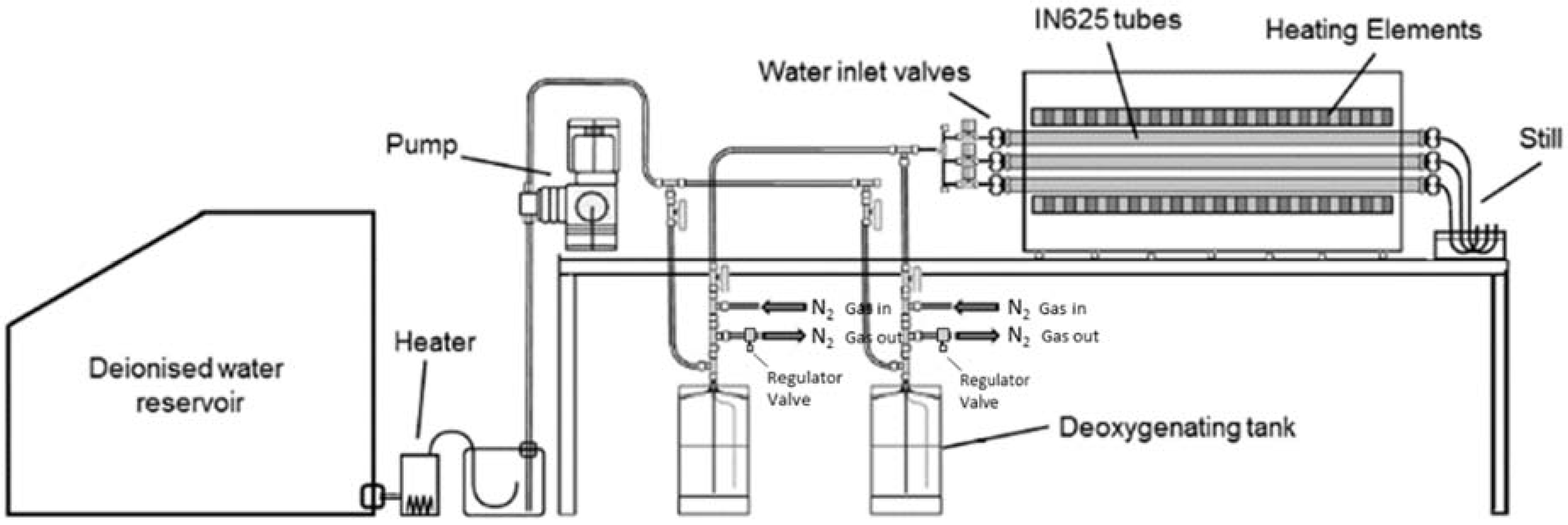
The exposures were carried out in tube furnaces (Lenton, Hope, UK) at 650 °C in 100% flowing steam environments. A diagram of the exposure rig is given in Figure 1. Water, from which the steam is generated, was first purified and de-aerated by boiling from a de-ionised external reservoir before being condensed back into a liquid and stored in metallic deoxygenating tanks under a positive pressure of nitrogen. Nitrogen on exit from the deoxygenating tanks is bubbled though water to prevent back diffusion of air into the tanks. The level of dissolved oxygen present in the steam was measured to be ~80 ppb. Water was introduced to one end of the tube furnace at a rate of ~0.33 g·min−1, using the positive pressure in the tanks (provided by the nitrogen) to generate flow of the water. Upon contact with the hot zone the water volatilises into steam producing a flow rate of ~1.42 m·min−1 given the tube ID of 25 mm and a specific volume of steam at 1 bar and 650 °C of 2.11 m3·kg
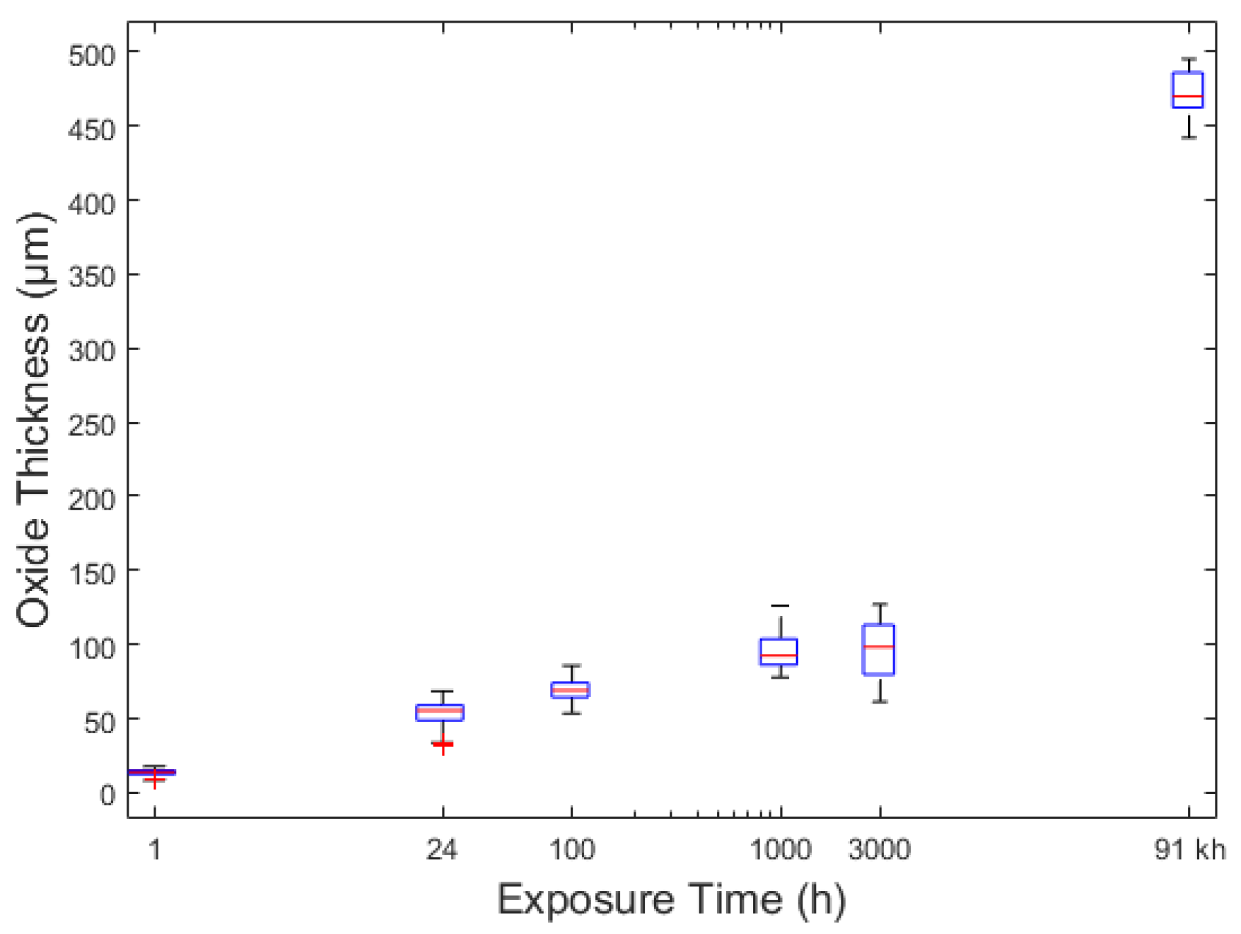
−1. Coupons were individually exposed for 0.25, 1, 3, 24, 100, 1000 and 3000 h. At the allotted exposure time the samples were removed from the furnace and allowed to cool in air.
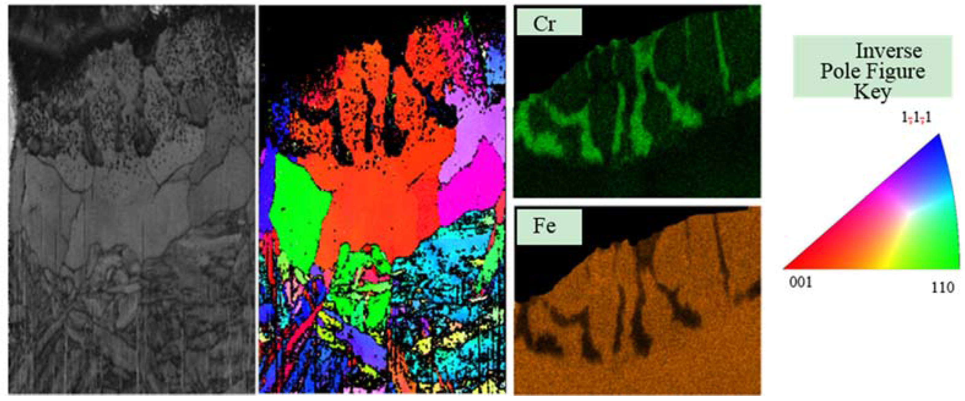
Both the laboratory exposed and plant exposed coupons were mounted in conductive Bakelite to allow for standard metallographic polishing to a finish of 1 µm diamond suspension. Care was taken to ensure that each successive polishing step removed the damage introduced by the previous step. The mounted samples were then suitable for SEM (scanning electron microscope) analysis. In the case of optical images and electron backscattered diffraction (EBSD) measurements, the samples were lightly etched using an abrasive colloidal silica polish for 3 min to bring out the grain structure and allow different phases to be observed using colour contrast and EBSD.
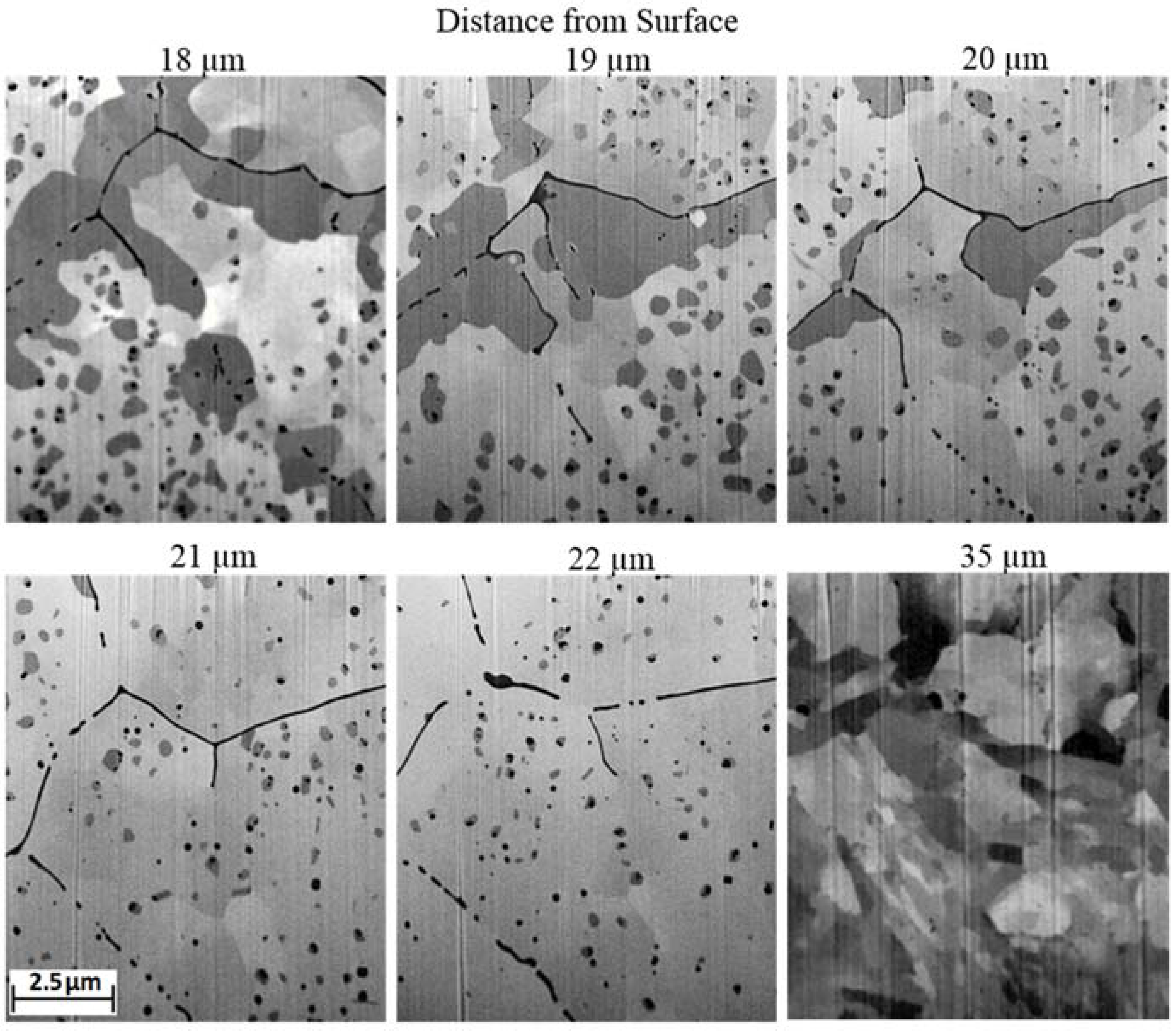
EDS (Energy Dispersive X-ray Spectroscopy) was performed in a Zeiss Auriga 60 focussed ion beam scanning electron microscope (Zeiss, Oberkocken, Germany) equipped with an Oxford Instruments 80 mm2 silicon drift EDS detector. The Zeiss Auriga 60 FIBSEM system is equipped with both an electron column and a Ga+ ion column positioned at 53° parallel to the e-beam direction allowing for simultaneous imaging and ion milling of the sample. The raster distance of the e-beam during imaging can be adjusted to correct for the tilt angle of the imaging face. The ability to mill a sample allows for the removal of successive slices of material in-between imaging stages thus building up a tomographic representation of a designated volume of interest. Due to the relatively large thickness of the oxides under investigation the samples were polished using standard metallographic techniques to allow access to the full depth of the scale. A volume of interest extending from the substrate alloy to the oxide surface approximately 10 µm wide was marked out and two trenches ~20 µm deep were milled on either side. A final trench was milled within the substrate ~20 µm deep to expose a face parallel to the original oxide surface which formed the first image in the tomographic dataset. Milling of the trenches was performed with an ion beam current of 16 nA at 30 keV. Accurate milling to produce the imaging surface was performed with an ion beam current of 1 nA at 30 keV. The region of interest on the image face was selected to be 10 µm by 10 µm positioned at 2 µm from the polished surface of the sample to disregard material that may have been damaged during the mechanical polishing phase or altered by the ion beam during the milling of the trenches. Even though the total imaging depth was only required to be 12 µm milling was performed to a depth of 20 µm to ensure a shear face with a minimal curvature near the bottom of the region of interest. The slice thickness was determined by the appreciable spot size of the ion beam at each current which is ~30 nm at 1 nA. Two slices were removed between each imaging phase resulting in a slice thickness of 60 nm. Top down images of the volume of interest were taken in-between regular milling phases throughout the procedure in order to correlate the average slice thickness with the expected amount of material removed.
Post processing of the images was performed in ImageJ (open source image manipulation software) to remove noise, align the slices, crop unwanted data and segment the images. The noise was removed using an edge retaining median filter. Alignment was achieved by registering features in the background of successive micrographs as these features did not undergo significant change between imaging phases. Due to the geometry of the system the background moves down in sequential images as it transitions into the foreground with successive slices. It was, therefore, necessary to translate the background aligned images to bring the imaging face into alignment, this effectively averages out the overall alignment with regards to slice thickness. Comparison between the background alignment and alignment of the top edge of the imaging face, which borders the polished surface, provides a measure of slice thickness.
Once the images were aligned unwanted data was cropped off to give a volume of interest 10 µm by 10 µm by the sample dependent depth. Significant features were then extracted using a combination of thresholding and neural net image segmentation before the data was imported into Aviso Fire, (FEI (Field Electron and Ion Co.), Hillsboro, AL, USA) for 3D visualisation and statistical analysis.

3. Results

3.1. Unexposed Grade 91 Tubing

The Grade 91 tubing exhibited a pre-existing oxide structure on its as-received inner surface up to a depth of 28 µm. The structure consisted of a chromium rich oxide extending from the inner surface of the tube to a maximum depth of ~23 µm. Figure 2 shows a cross-section of the near surface region of the inner surface in conjunction with EDS (energy dispersive x-ray spectroscopy) maps. The morphology exhibited by the chromium oxide resembles preferential grain boundary formation, however, EBSD analysis of the near surface region, given in Figure 3, shows that not all of the chromium oxide coincides with existing grain boundaries.
The fine grains observable towards the bottom of Figure 3 is typical of the martensitic lath structure typical of Grade 91 steel. The coarse grain structure in the near surface region is dissimilar to that of the bulk alloy and is consistent with a martensitic-ferritic transformation reported to occur in Grade 91 as a result of elemental depletion within the alloy due to the formation of the observed oxides [6].
Thin silicon oxide stingers, likely to be SiO2, shown in Figure 4 were also observed to be present from 15–23 µm which were encased by the chromium rich oxide but also extended a further ~5 µm into the alloy.
Figure 5 shows micrographs of a sample exposed for 1 h collected as part of the FIB tomographic data set. Images are collected in the plane parallel to the tubes inner surface at different depths from that surface and show that both the chromium and silicon oxides exhibited rod and plate shaped morphologies in a continuous matrix. Discrete chromium and silicon oxide particles with spherical and cuboidal morphologies are also observed within the alloy matrix. The bulk alloy martensitic lath grain structure is observable in the 35 µm image in Figure 5 and in the bottom of Figure 3.
Figure 6 shows a tomographic reconstruction of the near surface pre-existing SiO2. The SiO2 is present as fine discrete particles throughout the near surface region with larger discrete particles observable at the alloy surface. At depths between 18–28 µm SiO2 is present as an interconnected network of plate and rod shape structures. Pre-existing SiO2 exhibits an average volume fraction of ~2% with maximum values of ~5.5% near the alloy surface.

3.2. Laboratory Exposures

Figure 7 shows the oxidation progression with time for the pickled surface of Grade 91. Figure 7a shows the formation of a duplex scale consistent with predicted outer magnetite and inner spinel oxide layers. The pre-existing oxide is still observable within the substrate. Figure 7b shows that after 24 h the dissimilar grain structure of the near surface region has been consumed by alloy regression and both the pre-existing chromium rich and silicon oxides have become enveloped by the inward growing spinel layer. The enveloped pre-existing oxide demarcates the original alloy surface. The lightly contrasted regions at the oxide surface are indicative of hematite formation [11]. Micro-pores are observed to have formed within the spinel layer and large pores within the outer magnetite layer.
Spalled oxide was observed in the crucible after 1000 and 3000 h exposures. Compressive stress in the oxide layer can occur upon cooling of the sample due to the lower coefficient of thermal expansion (CTE) of oxides over the base alloy resulting in potential spallation [11]. Optical imaging of both the ground and pickled surfaces show signs of spallation of the outer magnetite layer. The 1000 h exposed coupon, shown in Figure 7d, exhibited significant void formation and laminar separation at the magnetite/spinel interface and featured a large outer hematite layer. The 3000 h exposed coupon, shown in Figure 7e, exhibited a thinner hematite layer than the 1000 h exposed coupon as well as a reduction in porosity both at the magnetite/spinel boundary and within the magnetite layer. Extensive porosity was still present at the magnetite/spinel interface of the 3000 h exposed coupon but located more within the spinel layer. The micro-pores were still present throughout the spinel layer after 3000 h.
Transverse cracks, shown in Figure 7b,c,e can be observed to have formed within the magnetite layer and are often, but not always, associated with hematite which forms at the crack edges.
Figure 8 shows an optical image of the pickled surface of the 3000 h exposed coupon which exhibited a purple hue at the oxide surface and at the magnetite/spinel interface associated with the porosity. This purple hue was present to a much lesser extent in the 3000 h exposed ground coupon and not present in large quantities at the surface of both the pickled and ground surface finish unspalled regions of the 1000 h exposed coupon.
Figure 9 shows EDS maps of the oxide scales in cross-section after exposure for 1, 100 and 3000 h to steam at 650 °C. The distributions of iron and chromium within the oxide scale, given in Figure 9a, are consistent with the expected magnetite/spinel duplex structure.
Figure 9b shows the oxide scale in cross-section after 100 h of exposure. The pre-existing oxide structure has been enveloped by the inwardly growing spinel scale but has retained its form and structure as shown by the chromium and inlayed silicon EDS maps. The spinel layer exhibits a reduced chromium content within the region adjacent to the pre-existing chromium rich oxide. The reduced chromium content emulates the chromium distribution in the substrate alloy prior to exposure as shown in Figure 2. The chromium concentration within the spinel layer increases from the denuded region adjacent to the pre-existing chromium rich oxide to the alloy/scale interface.
After 3000 h the spinel layer has formed stringers of undulating chromium concentration observable in Figure 9c with the most pronounced chromium concentration occurring at the alloy/scale boundary. Chromium depletion within the spinel layer and alloy is observed underneath the chromium stringers. Internal oxidation of chromium is also observed along the martensitic lath and prior austenitic grain boundaries of the substrate near the alloy/scale boundary and is mark by an x in Figure 9c.
Figure 10a provides scale thickness measurements for both the spinel layer and the total oxide thickness for both the ground and pickled surfaces of the Grade 91 coupons. Difficulties arose in defining the spinel/magnetite boundary due to porosity, which was previously located within the magnetite layer, associated with the spinel layer for the 3000 h exposed coupon. Difficulties in defining the spinel/magnetite boundary may have resulted in an under estimation of the spinel thickness. The pickled surface exhibited a reduction in the total scale thickness at 3000 h. The weight change data in Figure 10b is in good agreement with the literature [5,12]. The pickled surface exhibited a faster rate of scale formation for exposure times less than 1000 h, after 3000 h the ground surface exhibited the thicker scale.
The initial enhanced rate of oxide formation for the pickled surface is likely a consequence of chromium denudation in the near surface region due to the formation of the observed pre-existing chromia structure. The morphology of the pre-existing chromia structure does not convey any benefit to initial oxidation resistance.

3.3. Long Term Service Exposed

Figure 11 shows optical images of service exposed Grade 91 steel. The oxide structure was similar to that observed in the laboratory exposures with an inner spinel layer, featuring chromium rich stringers and micro-porosity, and an outer magnetite layer, featuring larger pores and hematite both on its outer surface and internally. Laminar porosity was present at the spinel/magnetite boundary and was associated with regions of spalled or damaged oxide shown in Figure 11c.
Transverse cracking occurred at regular intervals, with a periodicity of ~400 µm, which extended from the surface of the oxide up to three-quarters of the total scale thickness. Near the cracks within the spinel layer, a reduction in porosity can be observed. A reduction in the large laminar porosity present on the magnetite/spinel boundary is also observable within the vicinity of the cracks. Within the magnetite layer hematite has formed at the cracks boundaries. Regions of hematite and reduced porosity, marked in Figure 11c as hematite, are observed that are not associated with the presence of obvious transverse cracks.
Figure 12 shows the total oxide scale thickness for the pickled surface for both the laboratory exposures and the service exposed sample. The scale thickness after the 91kh exposure is greater than expected from extrapolating the laboratory results. There are some factors which influence the rate of scale growth that were not accounted for during the laboratory testing; these include the effect of elevated pressure, heat flux, thermal cycling or cooling of the sample down to ambient temperature during, for example, a planned shutdown. During a planned shutdown spallation or cracking of the outer layer of magnetite can occur and could enhance the rate of scale formation by reducing or dispersing the chromium within the spinel layer upon reheating of the material. The time periods between planned shutdowns are large and spallation events, if associated with sample cooling, may not occur until after 3000 h. As such it is difficult to extrapolate laboratory kinetics to such long term service exposures especially in the absence of detailed service records.
Figure 13 shows EDS chemical distribution maps across the oxide scale which formed on the inside surface of a section of service exposed Grade 91 tubing. The analysis area includes a transverse crack. In conjunction with the aforementioned chromium rich oxide stringers within the spinel layer, there is also a laminar region, marked x in Figure 13, of chromium rich oxide within the magnetite layer. This region features a chromium content similar to that of the spinel layer but with dissimilar morphology. The chromium rich oxide exhibits acicular or plate morphologies orientated with their long axis roughly perpendicular to the plane of the oxide scale surface. Silicon is observed throughout the spinel layer but is present in high concentration in regions associated with the laminar porosity at the magnetite/spinel boundary. FIB tomography of the oxide scale shows the silicon to be present in large discrete particles that border on the laminar pores. Molybdenum is present in the oxide scale near but not on the alloy/scale boundary. A significant reduction in scale porosity is observed in the vicinity of the molybdenum oxide. The incorporation of molybdenum into the scale has not altered the formation of chromium stringers and oxidation has continued to progress. Transverse cracking is not observed to have progressed through the molybdenum rich region of the scale. Laminar cracking is observed to have occurred within the spinel layer above the molybdenum rich region and can be seen in Figure 11c. A notable reduction in oxide porosity is observed within the molybdenum containing region of the spinel. Porosity then rises again as the molybdenum concentration within the scale decreases near the alloy/scale boundary.

4. Discussion

Unexposed material of similar age to the ex-service material was sourced from stores at the same plant to improve cross-comparison between laboratory and ex-service exposures. Unfortunately due to the age of the material a detailed account of its history was not available, it is therefore not possible to directly confirm their comparability. However, the samples exhibited similarities between their observed features making it reasonable to assume they both underwent a similar manufacture process, i.e., the distinct chromium rich layer, with morphology dissimilar from that of the laminar banding routinely observed in Grade 91, is similar to the pre-existing oxide structure.
The observation that the pre-existing oxide is not associated with grain boundaries suggests that either the mechanism by which the pre-existing oxide has formed is independent of grain boundaries or that the formation of the oxide precedes these grains. The latter would suggest that the pre-existing oxide structure formed during the normalisation phase of the heat treatment with the large grains coalescing around them upon tempering. Assuming this to be true conjecture may be added that the dissimilar grain structure observed near the surface can be attributed to an alteration in alloy chemistry, specifically a reduction in the presence of solid solution austenitic stabilisers, which ultimately resulted in the inefficacy of the heat treatment to induce the intended martensitic structure, instead forming larger ferritic grains.
Alternatively, the dissimilar grain structure could be attributed to mechanical abrasion of the tubes inner surface prior to heat treatment or in-between the normalisation and tempering phase and be independent of pickling. Mechanical abrasion introduces an amorphous region near the surface which upon heating undergoes healing processes resulting in recrystallisation. The amorphous layer initially nucleates numerous fine grains which grow and compete as the system attempts to reduce its surface free energy. During this period grain boundaries can be very mobile. The formation of the pre-existing internal oxide may, therefore, have been influenced by grain boundaries which were subsequently annihilated. It is difficult to gain access to the interior of small bore seamless tubes to mechanically remove scale which forms during the manufacturing process leading to the assumption that the inner surface is influenced by pickling, however, without a detailed account of the tubes history it is not possible to draw definite conclusions. Despite this the results presented in this paper highlight a potential discrepancy between standard laboratory practices and industrially produced steel tubing currently in service.
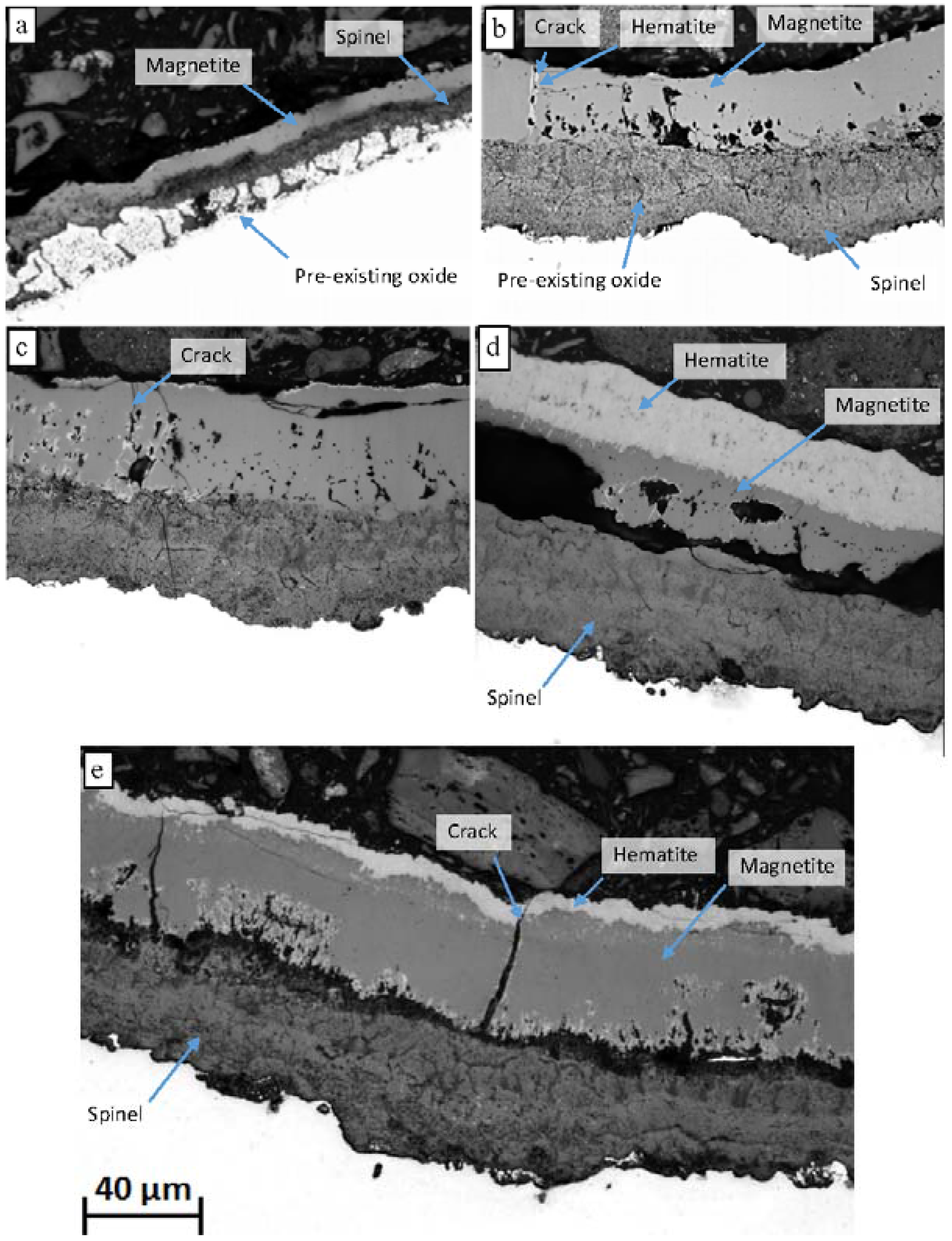
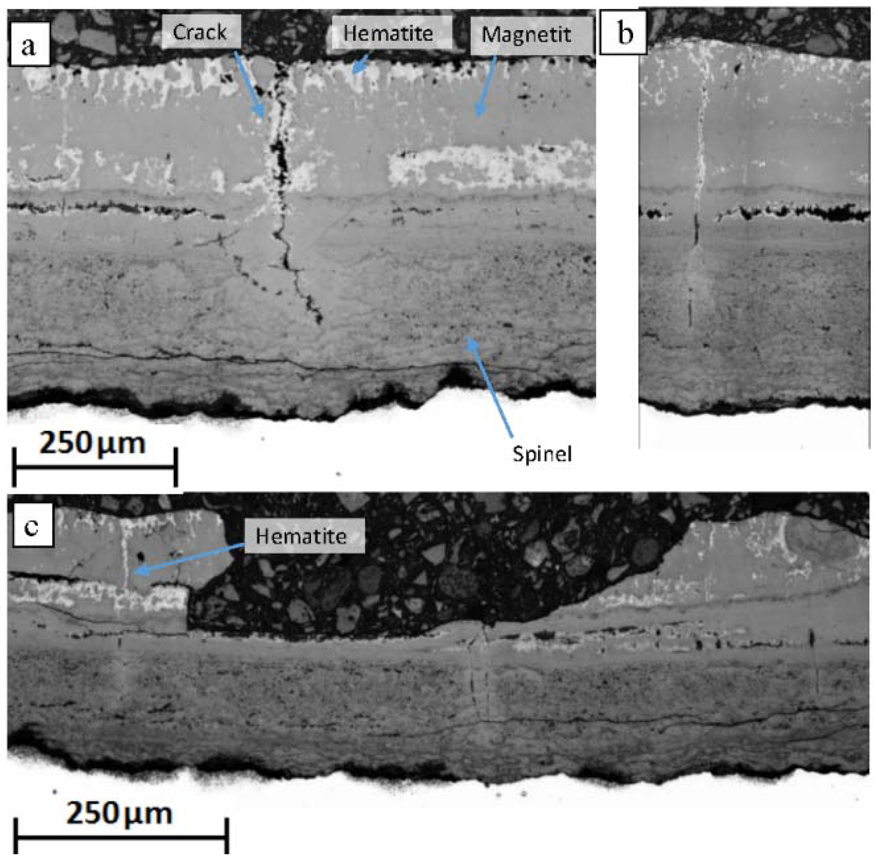
Upon exposure to the oxidising environment Grade 91 formed a multi-layered oxide scale consisting of an outer layer of magnetite, Fe3O4, which featured regions of the hematite, Fe2O3, at its surface and associated with cracks and pores, and an inner layer composed of Fe3O4 with (Fe, Cr, Mn)3O
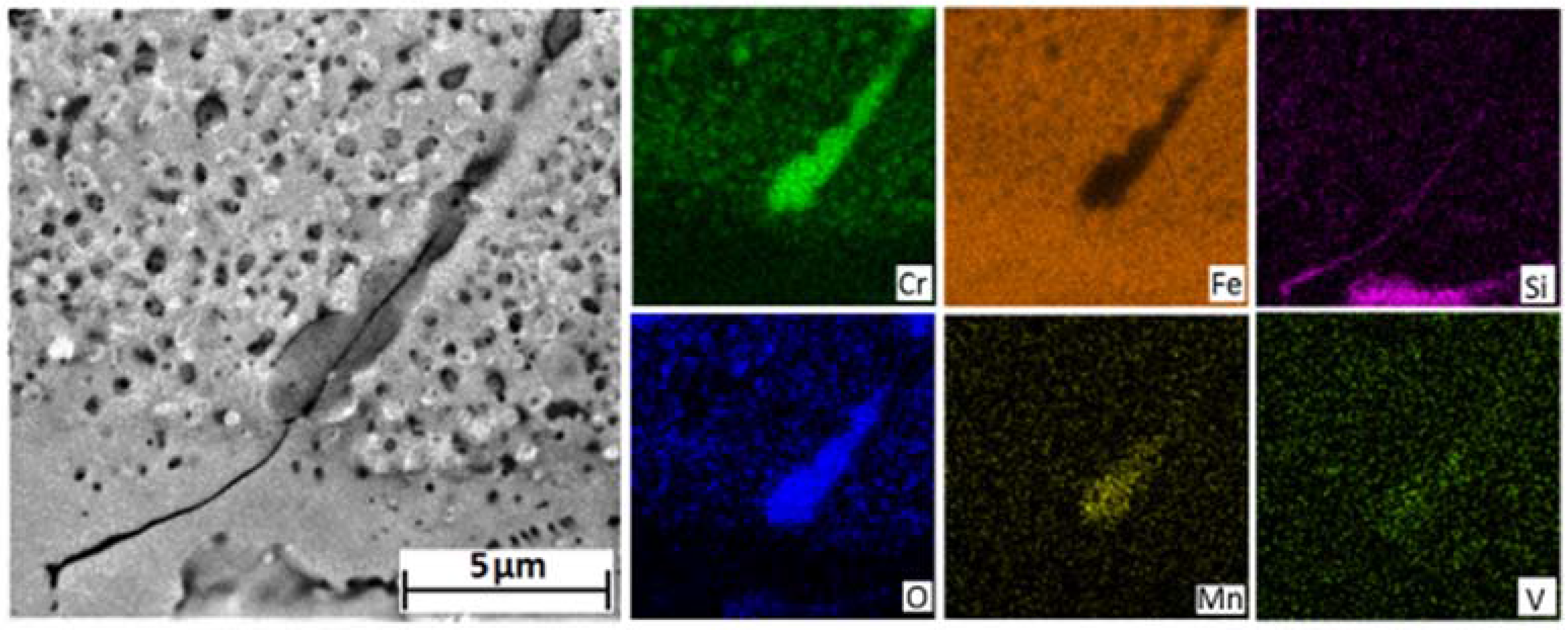
4 spinel stringers. The formation of the spinel stringers can be attributed to the alloy microstructure. Mo–Cr–Mn rich M23C6 carbides precipitate at lath and prior austenite boundaries in the bulk alloy and are oxidised near the alloy/scale boundary into (Cr, Mn)2O3 stringers encasing FeO [6,
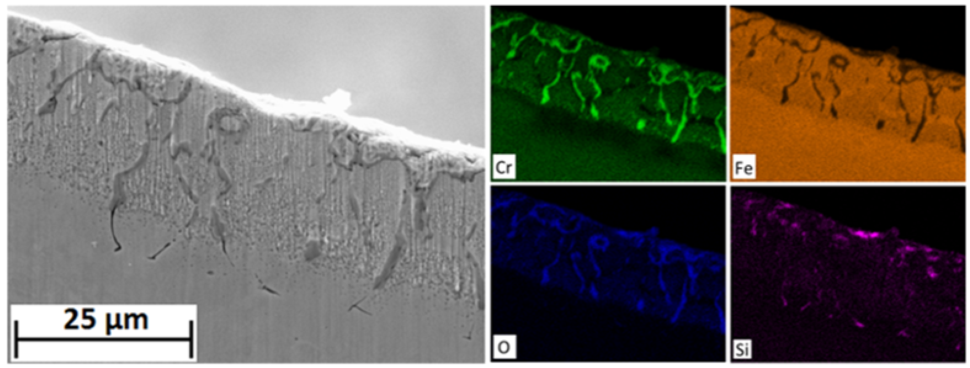
12]. These stringers are eventually incorporated into the inwardly growing spinel forming regions of undulating chromium concentration. The laminar, semi-continuous, morphology of these oxide stringers is likely to reduce the rate of scale growth as chromium forms stronger ionic bonds than iron and inhibits ionic diffusion.
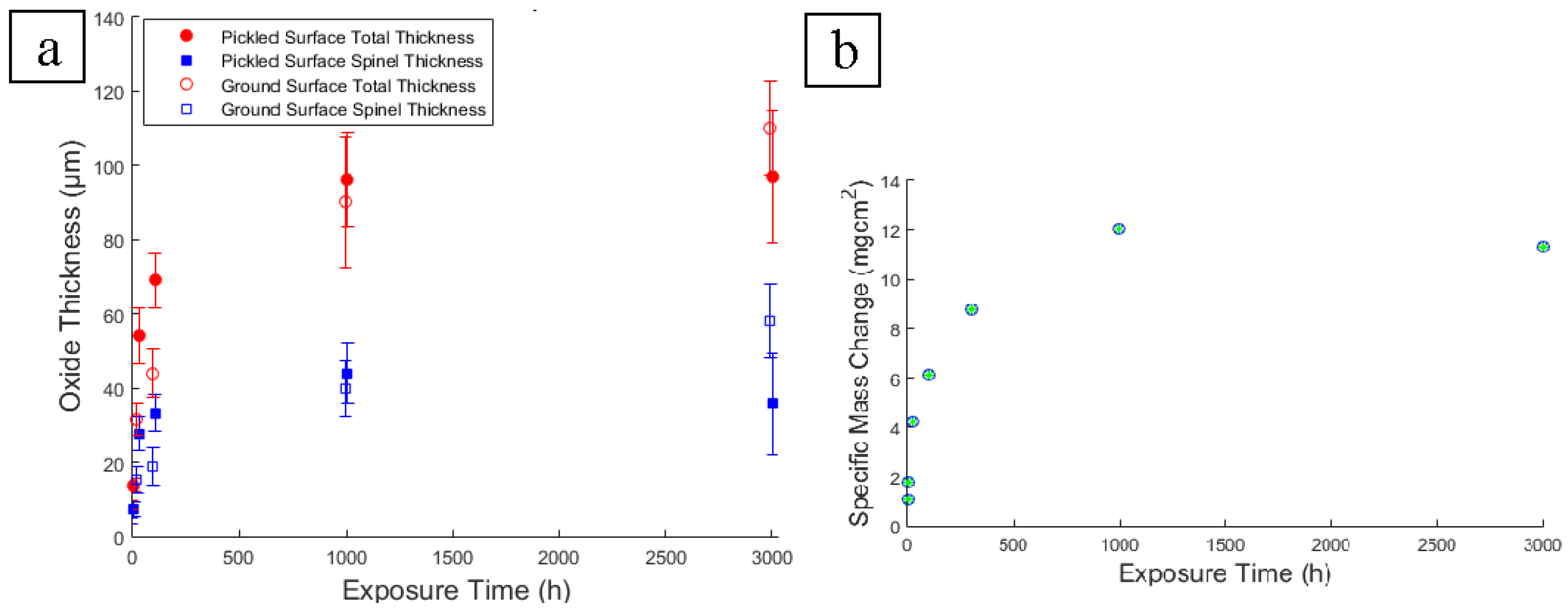
It is generally accepted that the rate of scale thickening for both the outer and inner layers is similar for the 9% Cr steels. The absence of large voids at the spinel/magnetite boundary and a thinner hematite layer on the 3000 h exposed sample could indicate a spallation event occurred in the interim between 1000 and 3000 h of exposure, however, the thickness of both the spinel and magnetite/hematite layers is comparable for both coupons. If spallation did not occur a mechanism is necessary for which the voids “heal”. The scale thickness measurements do not suggest spallation occurred during exposure. The reduction in total scale thickness observed for pickled surfaces between 1000 and 3000 h can be attributed to the densification of the oxide and removal of the large voids.
Porosity is observed in all coupons at all exposure times but is most extreme in the 1000 h sample. A change in the rate of iron diffusion through the spinel layer could account for vacancy condensation at the spinel/magnetite boundary. EDS of the alloy after 100 h show that the chromium rich stringers are not present within the spinel structure at that time. The absence of stringers can be attributed to the absence of M23C6 carbides within the alloy initially due to the presence of near surface chromium denuded ferrite grains and secondly due the absence of carbides at the martensitic and prior austenitic grain boundaries which need time to ripen. After 1000 h chromium rich stringers and internal Cr2O3 can be observed to have formed at the alloy/spinel boundary which inhibit iron diffusion into the scale. However, the oxide scale is still under the influence of the chemical potential gradient induced by the inward diffusion of oxygen thus iron within the scale will continue to diffuse outwardly. Iron diffusion is slower in (Fe,Cr,Mn)3O4 spinel than magnetite. A reduction in iron diffusion from the spinel layer leads to an increase in oxygen potential within the magnetite layer resulting in a transformation into hematite. Iron taken up into the hematite layer results in vacancy generation within the magnetite layer which coalesce at the spinal/magnetite boundary. Cavity formation may also be enhanced due to tensile stress induced by the volume increase associated with the magnetite-hematite phase change at the surface.
Magnetite is less thermodynamically stable than hematite at the oxygen partial pressures encountered in steam at 650 °C [13]. The presence of magnetite in the oxide scale is, therefore, a consequence of reaction kinetics resulting from a reduction in oxygen potential via the formation of new oxide both within the magnetite layer, via outward iron diffusion, and at the alloy/scale boundary, via oxygen ingress. If the delivery of iron to the magnetite layer is interrupted the oxygen activity rises sufficiently to induce a magnetite-hematite phase change [11]. Figure 7 shows the presence of a thick outer layer of hematite on the 1000 h exposed sample. Hematite formation could be ascribed to the presence of large voids at the spinel/magnetite boundary. The large voids prevent direct solid state diffusion thus halting the supply of iron to the oxide surface. Without the delivery of iron, the oxygen partial potential within the magnetite layer increases inducing a transformation of magnetite into hematite. Ionic diffusion through hematite is known to be slower than in magnetite [14]. With increasing oxygen partial pressure within the scale H2/H2O gas bridges become more favourable within the large voids [15]. This re-establishes oxygen ingress which slows the rate of increasing oxygen potential within the oxide. Furthermore, iron hydroxide vapour-phase diffusion thorough the voids is also more favourable at higher oxygen partial pressures and may establish outward iron diffusion [
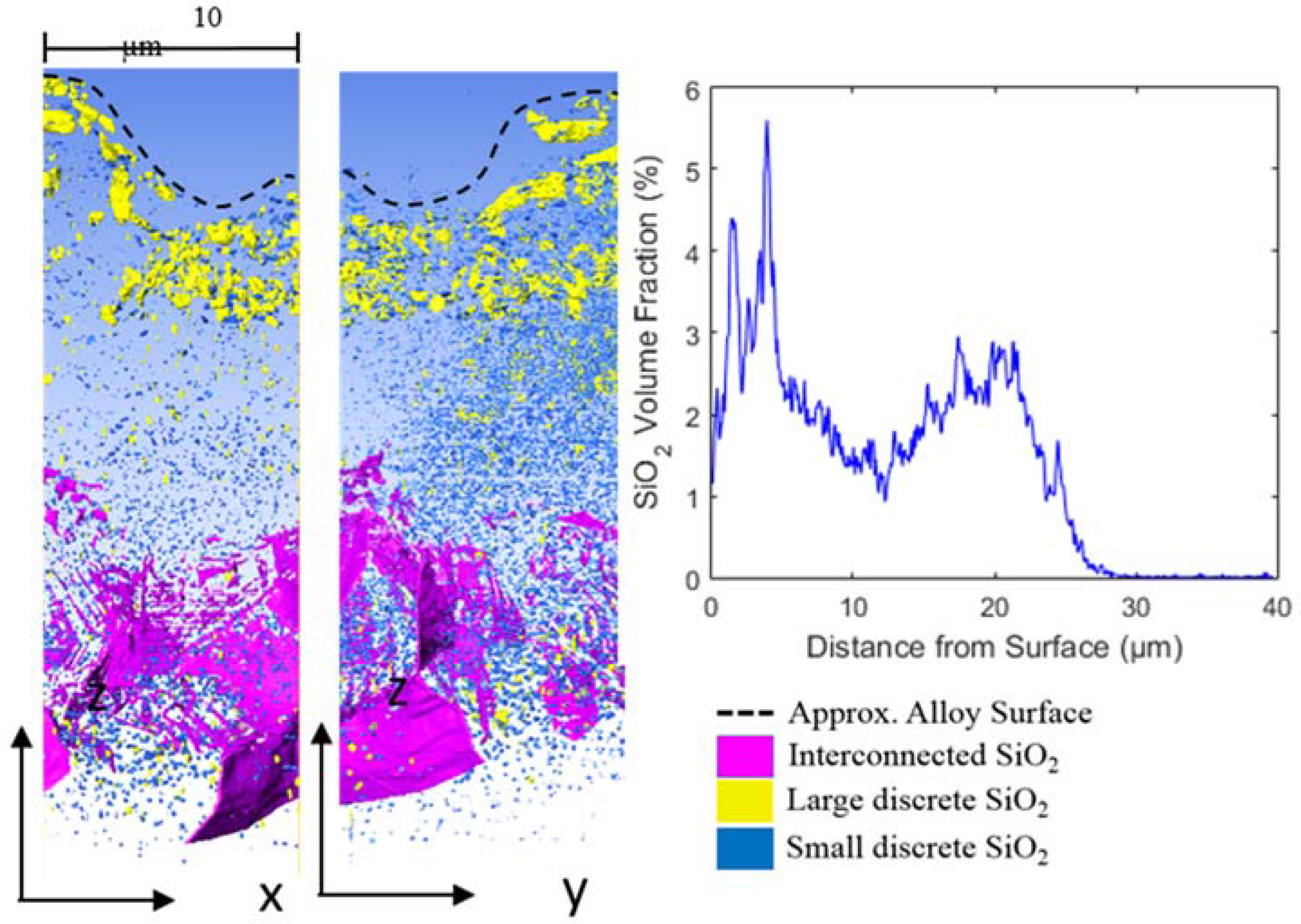
16]. Under these conditions new oxide forms on the inner edge of the pores eventually removing them and reinstating solid state diffusion. This process would remove not only the large laminar voids but also the porosity within the magnetite layer; a reduction of which is observed in the 3000 h exposed coupon. With the re-establishment of iron diffusion, hematite that does not lay on the surface is converted back into magnetite. Silicon may also play a role in reducing the oxygen partial pressure.
The addition of silicon to 9 Cr steels has been shown to reduce the rate of oxide formation [5,11,17]. It has been proposed that the formation of silicon oxide at the metal/oxide boundary, either as an internal oxide or as a continuous layer, inhibits ionic diffusion thereby reducing the rate of scale formation and delaying the onset of breakaway oxidation. Silicon is present in higher quantities at the surface of the 3000 h sample than the 1000 h sample. Silicon is shown to be associated with voids both at the spinel/magnetite boundary and within the magnetite layer of the 3000 h exposed sample. The H2/H2O gas bridge mechanism results in the formation of new oxide on the alloy side of the void with the potential for dissociation of oxide near the steam side of the void resulting in a gradual outward migration. The migration of voids could provide a transport mechanism for silicon from the spinel/magnetite boundary to the oxide surface where the presence of silica would provide a further layer of protection. The formation of a silica layer would also explain the observed transformation of the hematite in the 1000 h exposed sample back into a magnetite as shown in the 3000 h exposed sample.
An alternative explanation to pore migration for the reduction in porosity within the magnetite layer of the 3000 h exposed sample could be ascribed to the magnetite-hematite transformation. The transformation is associated with an increase in volume. Porosity within the oxide could, therefore, be reduced by plastic deformation or annihilation of vacancies within the hematite. However, such a volume change is unlikely to remove the laminar porosity observed at the spinal/magnetite boundary.
Through scale cracking has previously been observed and is accredited to the generation of tensile strain in the oxide during cooling [8,14]. Application of external tensile strain to uncracked pre-oxidised coupons of P91 generated transverse cracking similar to that observed for thermally grown oxides [18]. Cracking observed in the service exposed sample and associated regions of hematite can be attributed to thermal cycling of the material during plant operation, however, the presence of hematite associated with cracks in the laboratory samples suggests that some cracking occurred at elevated temperature. Alternatively, hematite formation could have occurred during cooling of the samples which was performed in air, however, only a small amount of hematite is observed on the surface of samples exposed for <100 h suggesting this did not occur. It can, therefore, be surmised that some cracking of the magnetite layer occurred during the exposure of the laboratory samples.
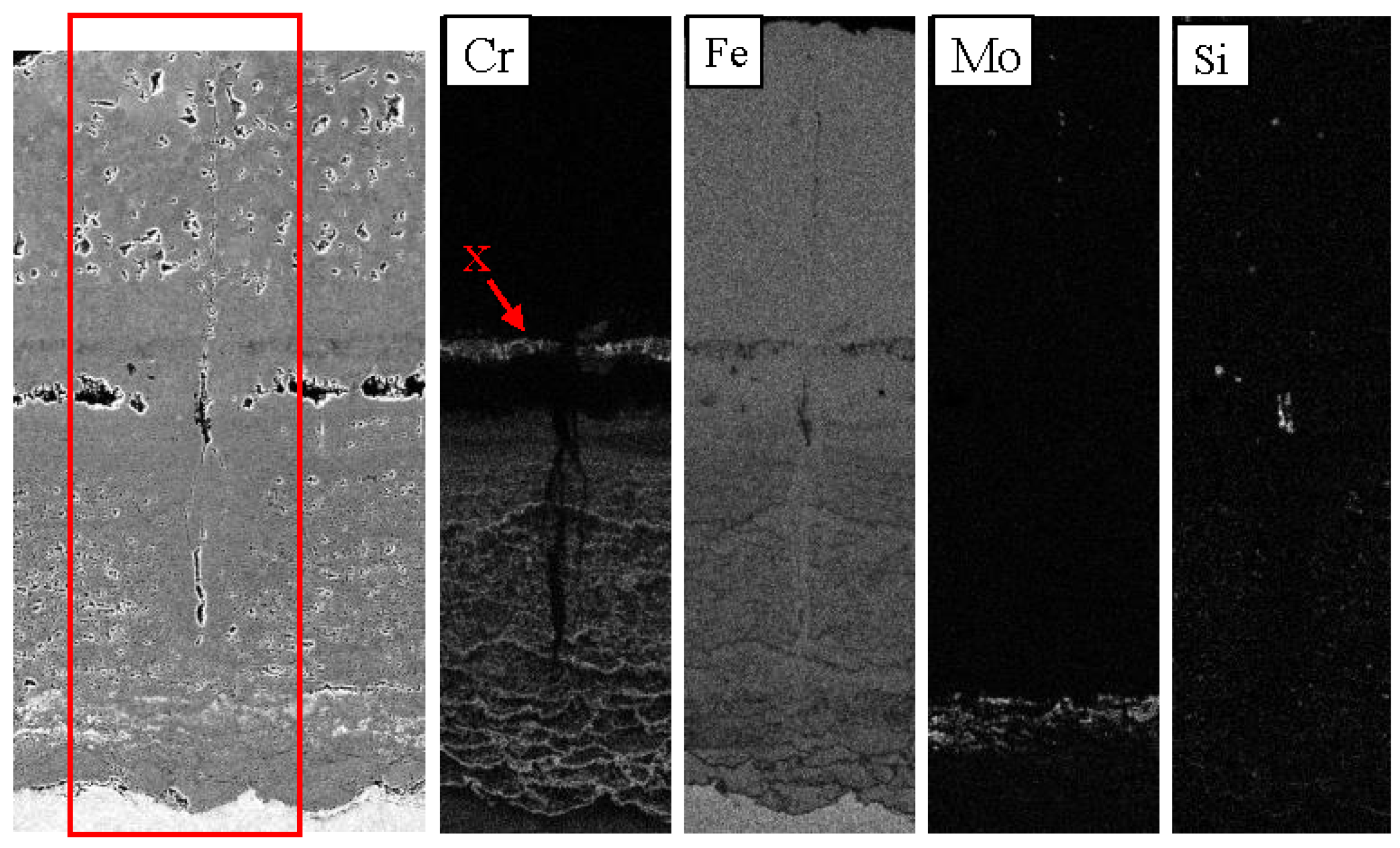
The service exposed material exhibited morphological changes in the oxide surrounding the transverse cracks suggesting that the oxide was subject to high temperatures after crack formation. The regions that exhibit features associated with transverse cracks but do not show the presence of a crack indicate the occurrence of a healing mechanism. The higher iron content within the spinel layer associated with the crack indicates the formation of magnetite. The volume increase associated with oxide formation within the scale would account for the reduction in porosity as vacancies within the spinel layer would be annihilated by the newly formed oxide. Even if a crack is sealed within the magnetite layer the crack cavity could still facilitate mass transport through the scale via the aforementioned vapour-phase diffusion mechanisms and the newly formed magnetite could provide a faster diffusion medium than the spinel. The transverse crack did not penetrate the region of the oxide containing molybdenum. It is unclear whether the presence of molybdenum has any influence on the crack progression as these cracks do not generally extend through the entire oxide scale when observed in oxides not containing molybdenum [14].
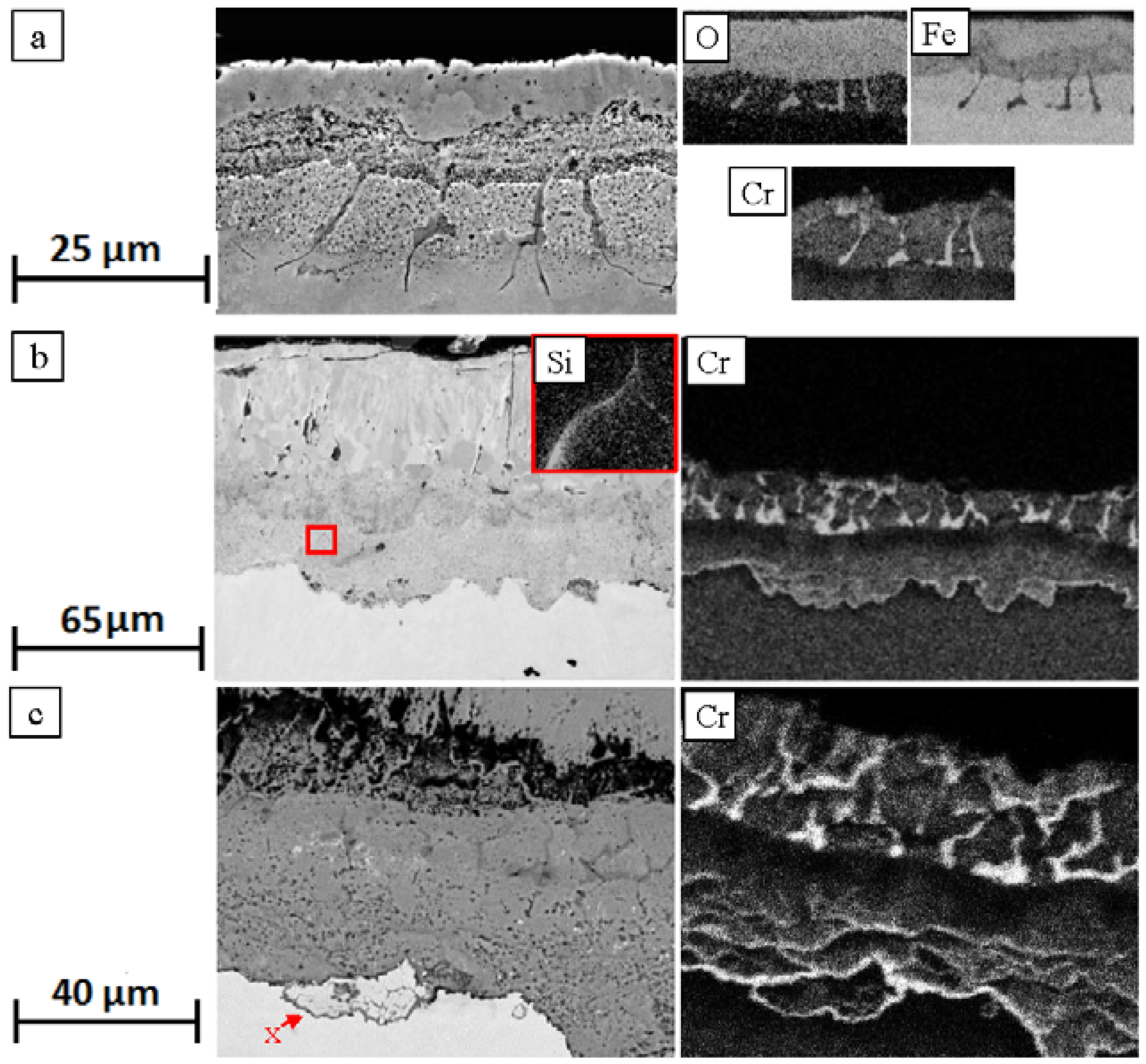
Molybdenum initially resists oxidation and remains within the alloy. Due to its large atomic size and slow rate of diffusion molybdenum is unable to re-equilibrate with the alloy and is thus concentrated near the alloy/scale boundary. Once the molybdenum concentration reaches a critical value and its chemical potential increases sufficiently for it to oxidise it is incorporated into the inwardly grown spinel layer.
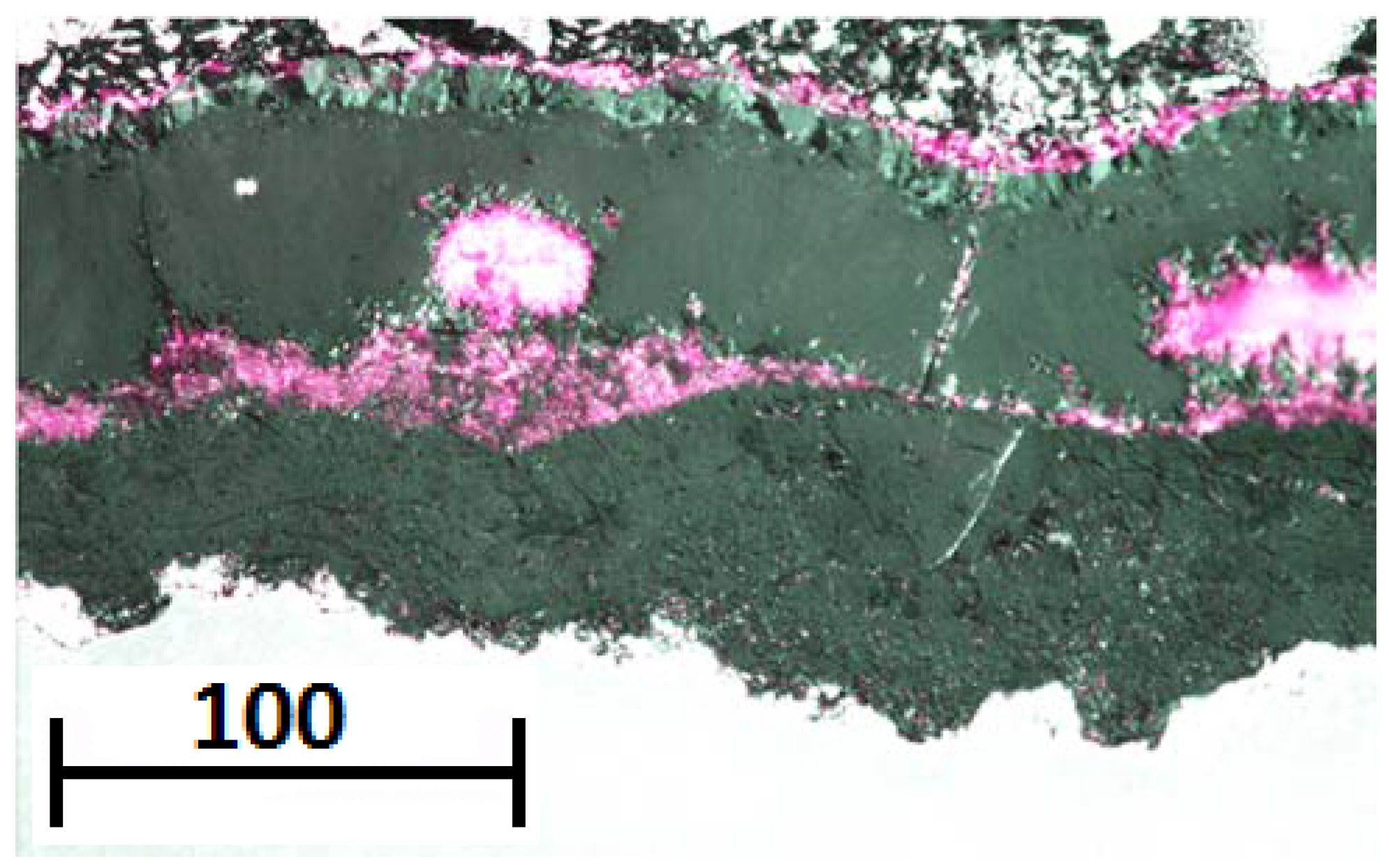
The service exposed sample showed the presence of a distinct chromium rich band within the magnetite layer. The band exhibited a chromium rich phase with morphology similar to that of the pre-existing oxide structure observed in the unexposed coupon. If this band is a remnant of the pre-existing oxide then it can be surmised that the spinel layer cannot have spalled during service. Underneath the chromium rich band magnetite is observed to have formed within, what was originally, the spinel layer. The formation of magnetite within the spinel layer can be attributed to the initial chromium depletion within the near surface ferritic grains of the unexposed material. The persistence of the chromium rich band emphasises the low diffusivity of chromium within the spinel oxide; silicon, however, is not observed with a similar morphology to the original pre-existing structure. Silicon is observed as discrete particles associated with the large voids underneath the chromium rich band. This demonstrates a greater mobility of silicon within the spinel oxide.

5. Conclusions

The manufacture of Grade 91 seamless steel tubing intended for steam boiler systems may result in the formation of a near surface region of dissimilar grain structure to that of the bulk alloy and internal formation of chromium and silicon oxides. This near surface region initially increases the rate of scale growth by delaying the formation of chromium rich banding within the spinel layer but has little influence on the scale growth kinetics after 3000 h. Comparisons between ground and pickled surfaces show the formation of a defined silica layer on the surface of the pickled sample which may influence long term oxidation kinetics, however, a defined silica layer is not observed on the 91 kh sample suggesting this layer is susceptible to spallation. Features observable in the 91 kh sample that are similar to the initial pre-existing oxide structure in the unexposed pickled samples indicate that pickling does not induce spallation of the spinel layer. The combined observations of long term exposures with scale growth kinetics show there is little appreciable difference in growth kinetics between ground and pickled samples surfaces for the 9Cr steels, however, alloys which oxidise more slowly, such as austenitic steels, may be more susceptible to alterations in kinetics due to deviations in oxide morphologies as a result of pickling. Further work is necessary to characterise the influence of industrial practices, such as pickling, on surface finish for different alloy systems and any deviations that may occur from standard ground surface laboratory testing.
Extensive laminar porosity was observed at 1000 h which resulted in spallation of the magnetite layer on cooling for the sample. Porosity was significantly reduced in the 3000 h exposed sample suggesting the action of a healing mechanism. The presence of laminar pores and hematite within the scale can be related to the oxygen potential which in-turn is influenced by the delivery of iron from the substrate and the formation of new oxide at the alloy/oxide boundary. In regions with high oxygen potential hematite forms reducing the rate of oxygen diffusion thus inhibiting further hematite formation. Where the oxygen potential increases porosity and cracks are healed due to vapour-phase diffusion processes and the volume increases associated with the magnetite-hematite or spinel-magnetite phase changes ultimately resulting in the densification of the oxide. This healing mechanism may explain why perpendicular regions of hematite exhibiting similar morphology to cracks are observed within the service exposed sample without the presence of cracks.
Transverse cracks were observed in the service exposed sample and have been associated with thermal cycling of the oxide scale. The occurrence of transverse crack could increase the rate of scale formation accounting for the large scale thickness of the 91 kh exposed sample.
Silicon is observed in higher quantities near the oxide surface after 3000 h than at 1000 h. The association of silica with pores within the magnetite layer of the 3000 h exposed sample suggests that pore migration is linked with the transport of silicon to the surface and could provide protection via the formation of an external barrier layer and by inhibiting vapour-phase diffusion within the pores. The absence of a discrete silicon layer on the oxide surface of the 91 kh service exposed sample suggests that the silica layer is susceptible to spallation.

Acknowledgements

The authors would like to thank the UK Department of Business, Innovation & Skills for providing funding and E.on UK for the provision of materials via Material-Component Performance-driven solution for Long-Term Efficiency Increase in Ultra Supercritical Power Plants (MACPLUS®) project.

Author Contributions

David M. Gorman and Anthony T. Fry conceived and designed the experiments; David M. Gorman prepared, exposed and analysed the samples. David M. Gorman and Anthony T. Fry wrote the paper.

Conflicts of Interest

The authors declare no conflicts of interest.

References

  1. A213/A213M-15c. Standard Specification for Seamless Ferritic and Austenitic Alloy-Steel Boiler, Superheater, and Heat-Exchanger Tubes; ASTM International: West Conshohocken, PA, USA, 2015. [Google Scholar]
  2. ISO/DIS 21608:2015. Corrosion of Metals and Alloys—Test Method for Isothermal Exposure Oxidation Testing under High Temperature Corrosion Conditions for Metallic Materials; International Organization of Standardization: Geneva, Switzerland, 2010. [Google Scholar]
  3. Ennis, P.; Czyrska-Filemonowicz, A. Recent advances in creep-resistant steels for power plant applications. Sadhana 2003, 28, 709–730. [Google Scholar] [CrossRef]
  4. Lee, N.H.; Kim, S.; Choe, B.H.; Yoon, K.B.; Kwon, D. Failure analysis of a boiler tube in USC coal power plant. Eng. Fail. Anal. 2009, 16, 2031–2035. [Google Scholar] [CrossRef]
  5. Fry, A.; Osgerby, S.; Wright, M. Oxidation of Alloys in Steam Environments: A Review; National Physical Laboratory: Teddington, UK, 2002. [Google Scholar]
  6. Mogire, E.; Higginson, R.; Fry, A.; Thomson, R. Microstructural characterization of oxide scales formed on steels P91 and P92. Mater. High Temp. 2011, 28, 361–368. [Google Scholar] [CrossRef]
  7. Wright, I.G.; Barry Dooley, R. Morphologies of oxide growth and exfoliation in superheater and reheater tubing of steam boiler. Mater. High Temp. 2011, 28, 40–57. [Google Scholar] [CrossRef]
  8. Armitt, J.; Holmes, R.; Manning, M.I.; Meadowcroft, D.B.; Metcalfe, E. The Spalling of Steam-grown Oxide from Superheater and Reheater Tube Steels: Final Report; Electric Power Research Institute: Leatherhead, UK, 1978. [Google Scholar]
  9. Schmidt, D.; Galetz, M.; Schütze, M. Improved oxidation resistance of ferritic-martensitic steels in water vapour containing environments via diffusion coatings. Mater. High Temp. 2012, 29, 159–165. [Google Scholar] [CrossRef]
  10. Sarver, J.; Tanzosh, J. Steamside oxidation behaviour of candidate USC materials at temperatures between 650 and 800 °C. Energy Mater. 2007, 2, 227–234. [Google Scholar] [CrossRef]
  11. Griess, J.; Maxwell, W. Long-Term Oxidation of Selected Alloys in Superheated Steam at 482 and 538/sup 0/C; Oak Ridge National Lab.: Oak Ridge, TN, USA, 1981. [Google Scholar]
  12. Ehlers, J.; Young, D.; Smaardijk, E.; Tyagi, A.; Penkalla, H.; Singheiser, L.; Quadakkers, W. Enhanced oxidation of the 9% Cr steel P91 in water vapour containing environments. Corros. Sci. 2006, 48, 3428–3454. [Google Scholar] [CrossRef]
  13. Davies, H.; Dinsdale, A. Theoretical study of steam grown oxides as a function of temperature, pressure and p(O2). Mater. High Temp. 2005, 22, 15–25. [Google Scholar] [CrossRef]
  14. Quadakkers, W.; Ennis, P.; Zurek, J.; Michalik, M. Steam oxidation of ferritic steels-laboratory test kinetic data. Mater. High Temp. 2005, 22, 47–60. [Google Scholar] [CrossRef]
  15. Rahmel, A.; Tobolski, J. Einfluss von wasserdampf und kohlendioxyd auf die oxydation von eisen in sauerstoff bei hohen temperaturen. Corros. Sci. 1965, 5, 333–346. [Google Scholar] [CrossRef]
  16. Surman, P. The oxidation of iron at controlled oxygen partial pressures—I. Hydrogen/water vapour. Corros. Sci. 1973, 13, 113–124. [Google Scholar] [CrossRef]
  17. Angell, M.G.; Lister, S.K.; Rudge, A. The effect of steam pressure on the oxidation behaviour of annealed 9Cr 1Mo boiler tubing materials. In 15th International Conference on the Properties of Water and Steam (ICPWS XV), Berlin, Germany, 2008.
  18. Otsuka, N. Fracture behavior of steam-grown oxide scales formed on 2%–12% Cr steels. Mater. High Temp. 2005, 22, 131–138. [Google Scholar] [CrossRef]
Figure 1. Diagrammatical representation of the one bar pressure steam loop.
Metals 06 00062 g001
Figure 2. Cross-section of the inner surface of unexposed Grade 91 tubing showing the presence of pre-existing internal oxidation and chromium depletion region.
Metals 06 00062 g002
Figure 3. Electron backscatter diffraction image quality and inverse pole figure maps with relative chemical distribution of the inside surface of unexposed Grade 91 tube steel subjected to pickling.
Metals 06 00062 g003
Figure 4. Cap Energy dispersive x-ray spectroscopy relative chemical distribution maps of the near surface pre-existing oxide present at the inner surface of pickling Grade 91 tube steel.
Metals 06 00062 g004
Figure 5. Shows scanning electron microscope micrographs at increasing depth from the oxide surface taken parallel to the plane of the oxide surface.
Metals 06 00062 g005
Figure 6. Focused ion beam tomographic reconstruction of SiO2 formed in the near surface region of unexposed Grade 91 steel subjected to pickling.
Metals 06 00062 g006
Figure 7. SEM micrographs of Grade 91 steel exposed to 1 bar steam at 650 °C for (a) 1 h, (b) 24 h, (c) 100 h, (d) 1000 h and (e) 3000 h.
Metals 06 00062 g007
Figure 8. Optical image of Grade 91 steel exposed to flowing 1 bar steam at 650 °C for 3000 h.
Metals 06 00062 g008
Figure 9. Backscatter SEM micrographs with chromium EDS (Energy Dispersive X-ray Spectroscopy) map for Grade 91 exposed to steam for (a) 1 h, (b) 100 h and (c) 3000 h. (b) Inset silicon EDS map in micrograph.
Metals 06 00062 g009
Figure 10. (a) Oxide thickness measurements taken on optical images using an average distance between lines method and (b) specific mass change of laboratory exposed coupons of Grade 91 tube steel.
Metals 06 00062 g010
Figure 11. Light micrographs of T91 exposed in plant for 91 kh in the temperature range 500–650 °C at elevated pressures showing (a,b) through thickness cracking and (c)region of spalled oxide.
Metals 06 00062 g011
Figure 12. Optically measured total oxide scale thickness performed using a distance between two lines method. The boxplot relates to the mean, upper and low quartiles and 98th and 2nd percentiles of the measurements.
Metals 06 00062 g012
Figure 13. EDS maps of the cross-sectioned oxide scale of Grade 91 steel exposed in service at 500–650 °C for 91 kh, the red box marketed the EDS analysis area
Metals 06 00062 g013
Table 1. Wt.% Composition of T91 measured using energy dispersive x-ray spectroscopy. * Values quoted from literature [1].
MaterialFeCrMoSiMnVNiCuNPSC
laboratory exposureballance8.880.960.40.60.210.20.160.05 *<0.02 *<0.01 *0.1 *
service exposureballance9.160.890.60.590.240.110.10.05 *<0.02 *<0.01 *0.1 *

