
Effect of Different Current Values on Microstructure and Mechanical Properties of Microalloyed Steels Joined by the Submerged Arc Welding Method


Abstract
:1. Introduction
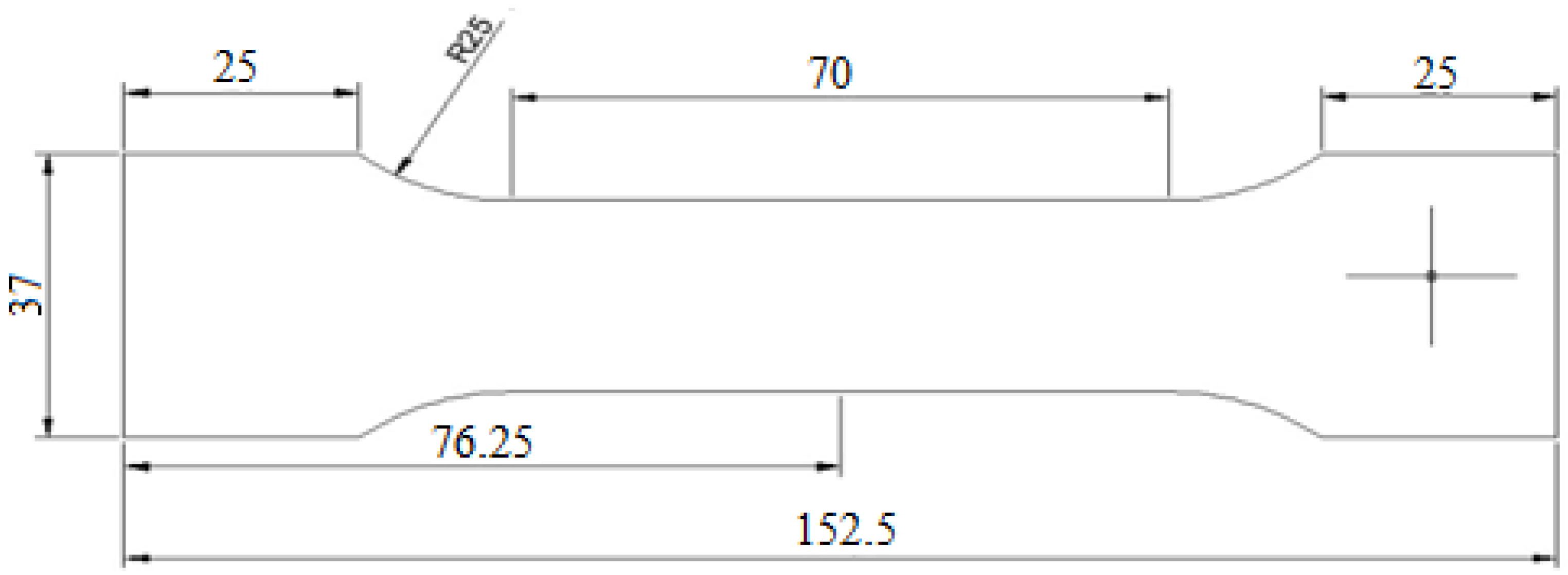
2. Materials and Experimental Techniques
3. Results and Discussion
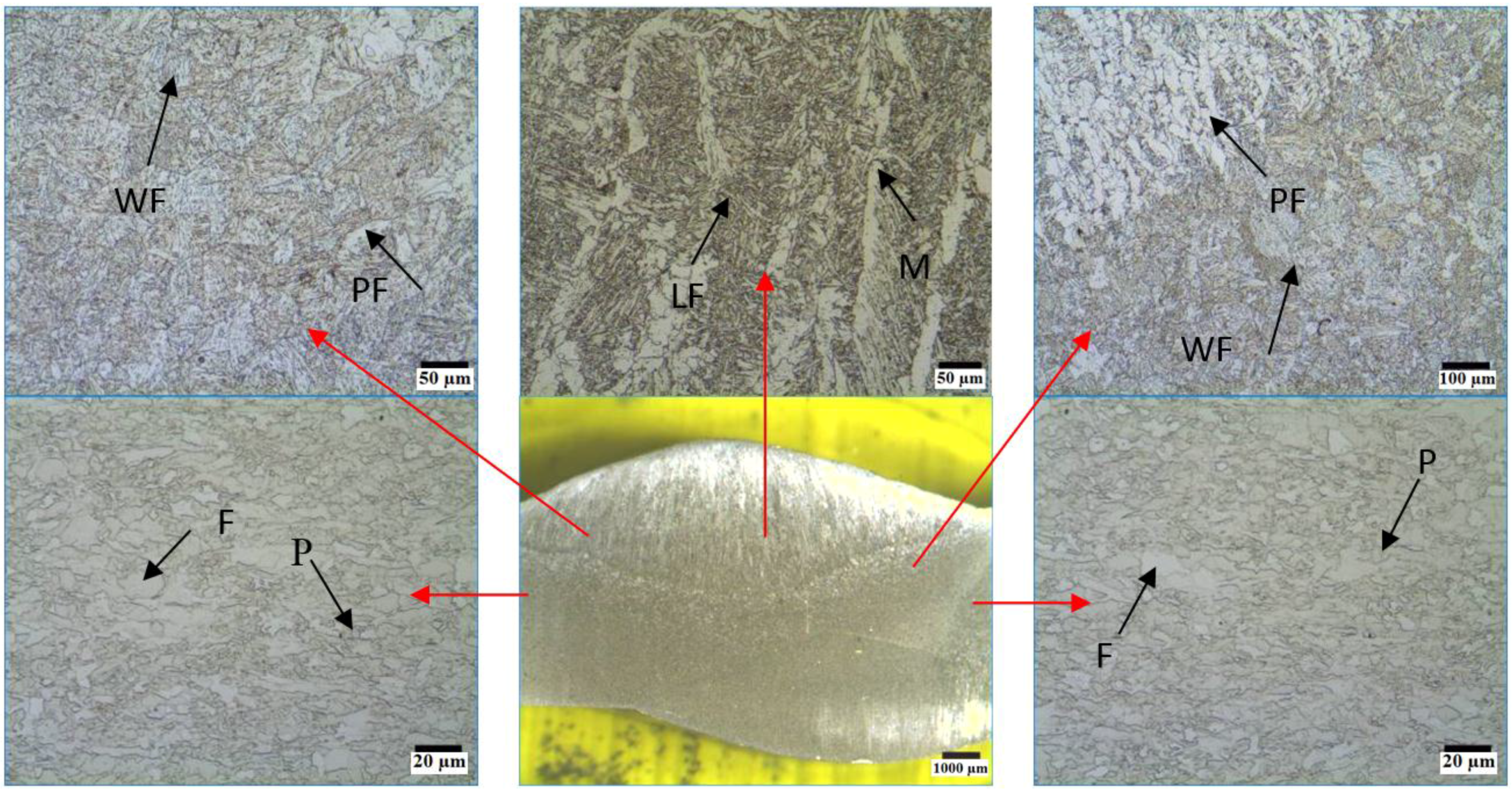
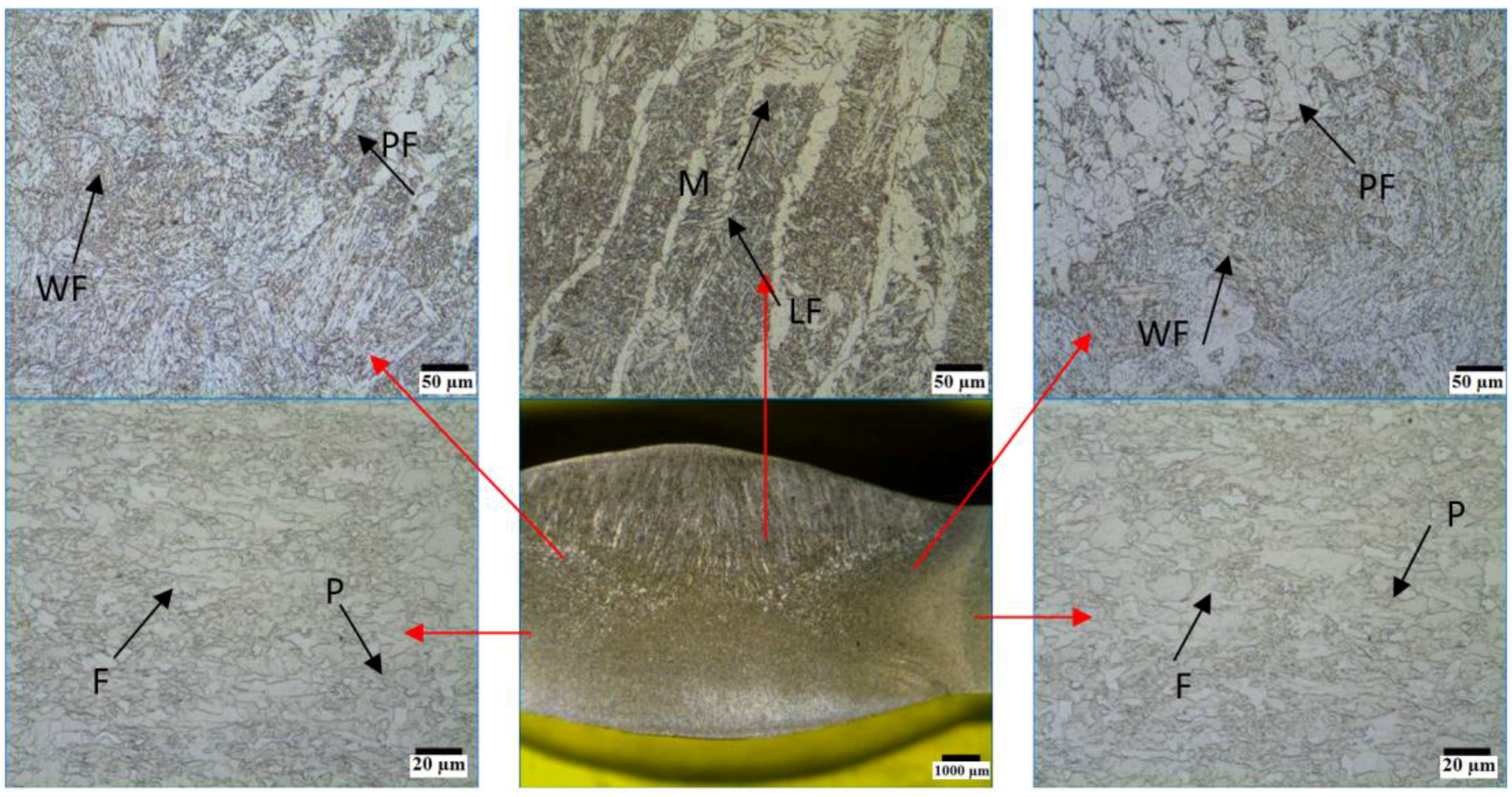
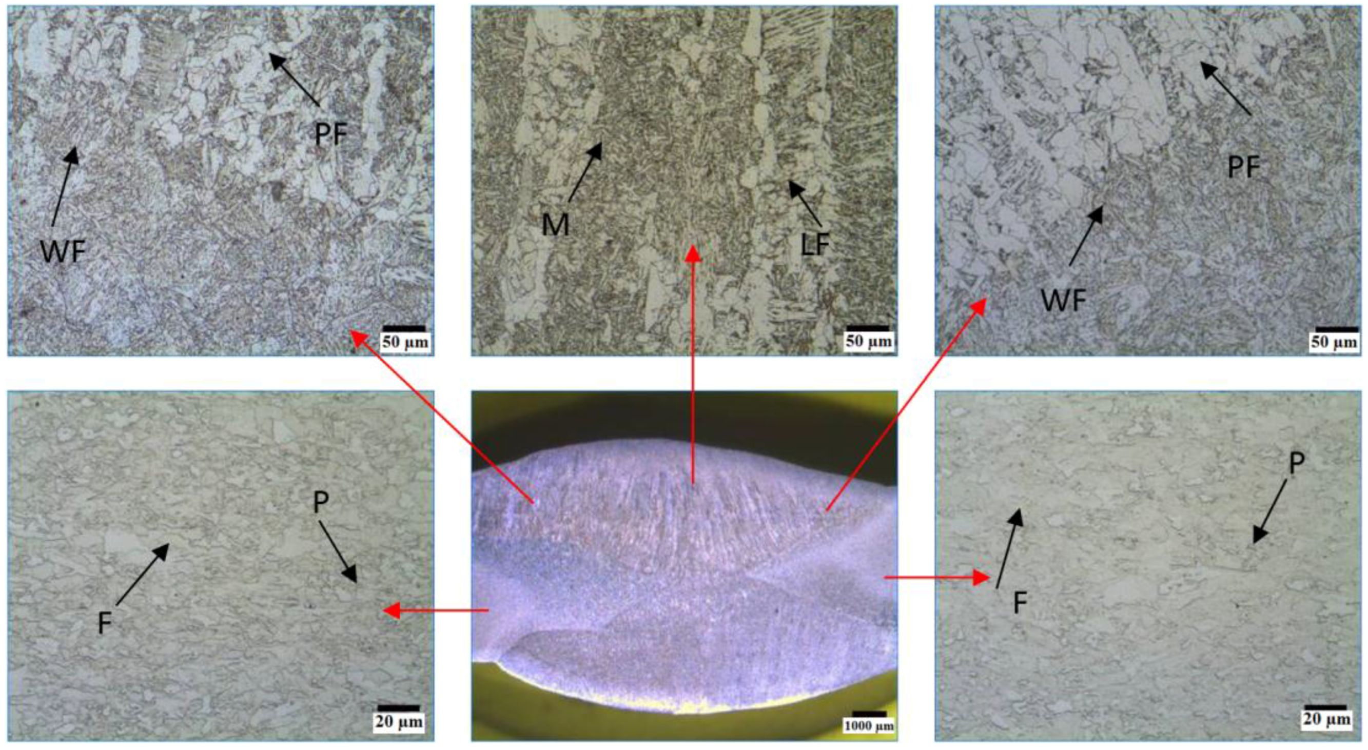
3.1. Microstructure
3.2. Mechanical Properties
4. Conclusions
- The initial microstructure of the steel used in this study consisted of ferrite and pearlite structure. However, the weld metal of all welded samples has polygonal ferrite and plate ferrite near the HAZ. Widmanstatten ferrite and a small amount of martensite was also observed in the center of the weld metal.
- An increase in the welding current caused an increase in the heat input. As a result of this, samples welded at higher welding currents showed a wider HAZ compared to the samples welded at lower welding currents.
- The highest ultimate tensile strength was measured as 665 MPa in the sample S2, welded at a welding current of 400 A. This is due to the formation of Widmanstaten ferrite in the transition area of the welded joints. An increase in the welding current raised the heat input which encouraged the formation of Widmanstatten ferrite.
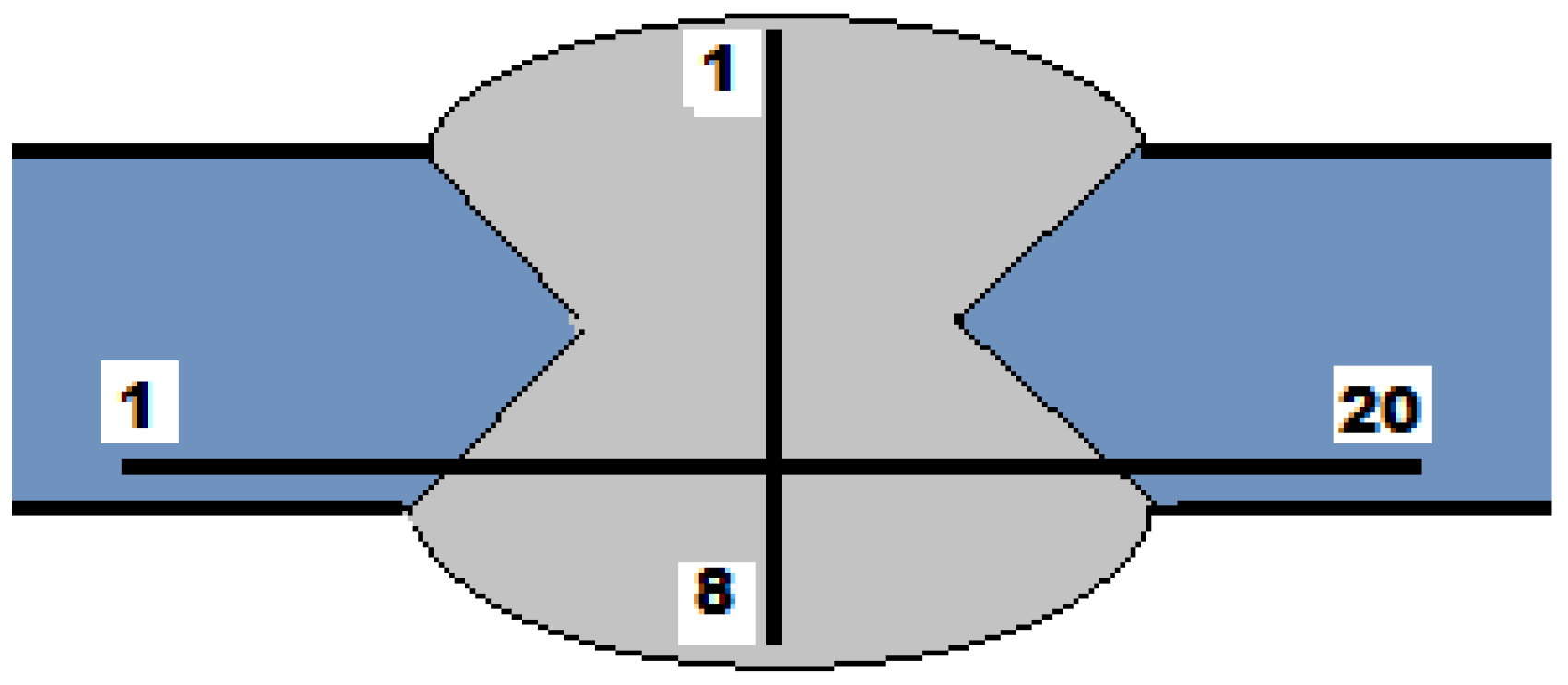
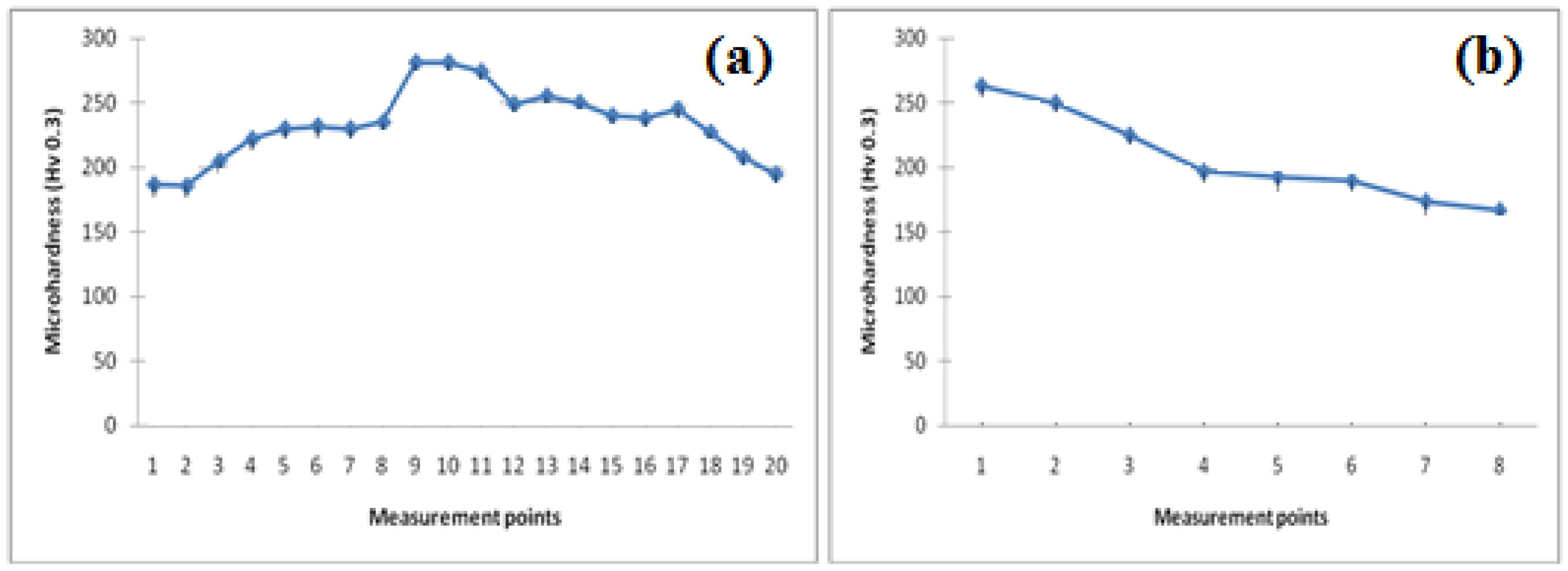
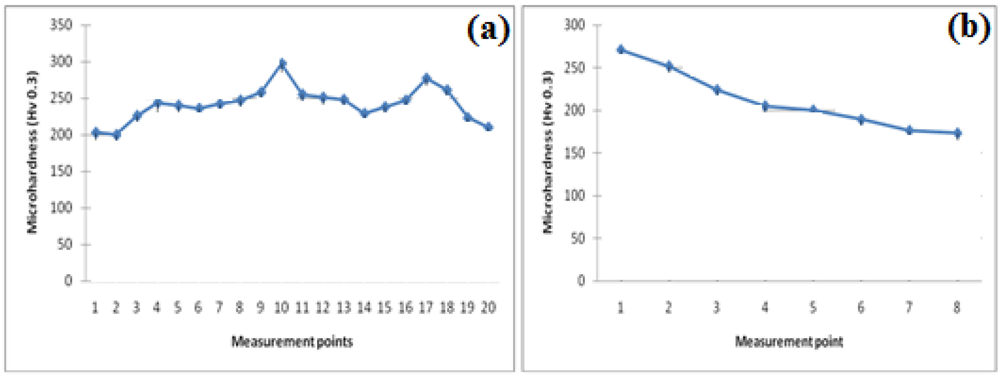
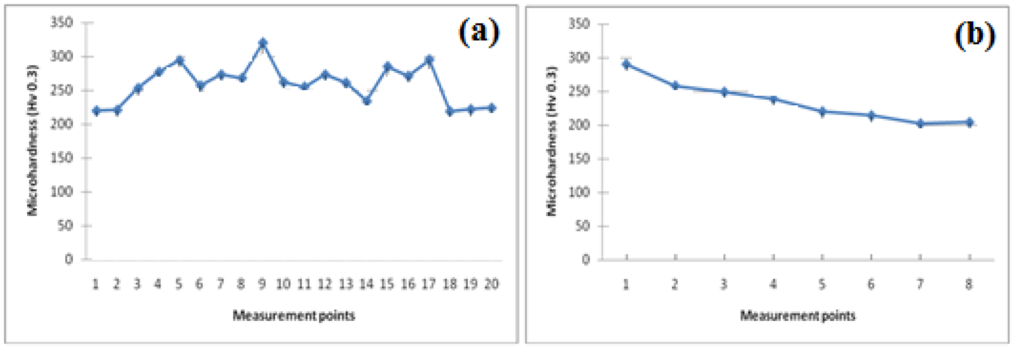
- The highest hardness of 281 HV, 297 HV and 320 HV was obtained in the weld metal for samples S1, S2 and S3 respectively. In general, as the welding current increases, it is possible that more widmanstatten ferrite or martensitic structure can be formed in the weld center because of large austenite grains and a high cooling rate.
Author Contributions
Conflicts of Interest
References
- Matlock, D.K.; Krauss, G.; Speer, J.G. Microstructures and properties of direct cooled microalloy forging steels. J. Mater. Process. Technol. 2001, 117, 324–328. [Google Scholar] [CrossRef]
- Balart, M.J.; Davis, C.L.; Strangwood, M. Fracture behaviour in medium-carbon Ti–V–N and V–N microalloyed ferritic-pearlitic and bainitic forging steels with enhanced machinability. Mater. Sci. Eng. A 2002, 328, 48–57. [Google Scholar] [CrossRef]
- Khalid, F.A. Precipitation and compositional changes in the structural phases of microalloyed automotive steels. Mater. Sci. Eng. A 2002, 325, 281–285. [Google Scholar] [CrossRef]
- Gündüz, S.; Acarer, M. High-temperature tensile and wear behaviour of microalloyed medium carbon steel. Ind. Lubr. Tribol. 2005, 57, 145–149. [Google Scholar] [CrossRef]
- Gladman, T. The Physical Metallurgy of Microalloyed Steels, 1st ed.; The Institute of Materials: London, UK, 1997. [Google Scholar]
- Parsons, S.A.; Edmonds, D.V. Microstructure and mechanical properties of medium-carbon ferrite-pearlite steels microalloyed with vanadium. Mater. Sci. Technol. 1987, 3, 894–904. [Google Scholar] [CrossRef]
- Gündüz, S.; Acarer, M. The effect of heat treatment on high temperature mechanical properties of microalloyed medium carbon steel. Mater. Des. 2006, 27, 1076–1085. [Google Scholar] [CrossRef]
- Erden, M.A.; Gündüz, S.; Türkmen, M.; Karabulut, H. Microstructural characterization and mechanical properties of microalloyed powder metallurgy steels. Mater. Sci. Eng. A 2014, 616, 201–206. [Google Scholar] [CrossRef]
- Olson, D.L.; Siewert, T.A.; Liu, S.; Edwards, G.R. ASM Handbook Volume 6: Welding, Brazing and Soldering, 9th ed.; ASM International: Metals Park, OH, USA, 1983; Volume 6. [Google Scholar]
- American Welding Society (AWS). Welding Handbook, 8th ed.; AWS: Miami, FL, USA, 1995. [Google Scholar]
- Bajic, N.; Zeravcic, V.S.; Bobic, B.; Cikara, D.; Arsic, M. Filler metal influence on weld metal structure of microalloyed steel. Weld. J. 2011, 90, 55–62. [Google Scholar]
- Hunt, A.C.; Kluken, A.O.; Edwards, G.R. Heat input and dilution effects in microalloyed steel weld metals. Weld. J. 1994, 73, 9–15. [Google Scholar]
- TS EN ISO 4136. Destructive Tests on Welds in Metallic Materials—Transverse Tensile Test; Turkish Standardization Institute: Ankara, Turkey, 2013. [Google Scholar]
- Welding Institute. Compendium of Weld Metal Microstructures and Properties; The Welding Institute: Cambridge, UK, 1985. [Google Scholar]
- Babu, S.S.; Bhadeshia, H.K.D.H. Transformation from bainite to acicular ferrite in reheated Fe–Cr–C weld deposites. Mater. Sci. Technol. 1990, 6, 1005–1019. [Google Scholar] [CrossRef]
- Esmailian, M. The effect of cooling rate and austenite grain size on the austenite to ferrite transformation temperature and different ferrite morphologies in microalloyed steels. Iran. J. Mater. Sci. Eng. 2010, 7, 7–14. [Google Scholar]
- Unlu, B.S.; Yılmaz, S.S.; Uzkut, M. Microstructure and mechanical properties of welding zone by mig/mag welding joined at different currents. In Proceedings of the 6th International Advanced Technologies Symposium, Elazığ, Turkey, 16–18 May 2011.
- Suresh, M.V.; Krishna, B.V.; Venugopal, P.; Rao, K.P. Effect of pulse frequency in gas tungsten arc welding of powder metallurgical preforms. Sci. Technol. Weld. Join. 2004, 9, 362–368. [Google Scholar] [CrossRef]
- Bodnar, R.L.; Hansen, S.S. Effects of Widmanstätten ferrite on the mechanical properties of a 0.2 pct C-0.7 pct Mn steel. Metall. Mater. Trans. A 1994, 25, 763–773. [Google Scholar] [CrossRef]
- Gondoh, H.; Sato, M.; Kanaya, K.; Miyasaka, A.; Yoshida, I. Behaviour of nitrogen, nitrides, carbides in weld HAZ. Trans. Iron Steel Inst. Jpn. 1981, 10, 444–448. [Google Scholar]
- Kurşun, T.; Teker, T. Effect on microstructure and hardness of synergic controlled pulsed (MIG-P) and manual (MIG) welding of AISI430/AISI1030 steel couples. Electron. J. Mach. Technol. 2008, 8, 27–37. [Google Scholar]
- Lord, M. Interpass temperature and the welding of strong steels. Weld. World 1998, 41, 452–459. [Google Scholar]
- Kara, S.; Korkut, M.H. Investigation the effect of welding groove on metallurgical and mechanical properties in armor steels. Electron. J. Mach. Technol. 2012, 9, 35–45. [Google Scholar]


| Materials | C | Si | Mn | P | S | Cr | Ni | Mo | V | Nb | Ti |
|---|---|---|---|---|---|---|---|---|---|---|---|
| Microalloyed Steel | 0.13 | 0.8 | 1.02 | 0.02 | 0.01 | 1.50 | 1.1 | 0.33 | 0.1 | 0.06 | 0.05 |
| Oerlikon S2 (SAW wire) | 0.08 | 0.6 | 1.3 | 0.025 | 0.025 | - | - | - | - | - | - |
| Sample No. | Welding Parameters | |||
|---|---|---|---|---|
| Current (A) | Voltage (V) | Welding Speed (cm/min) | Heat Input (kJ/mm) | |
| S1 | 350 | 30–32 | 42 | 1.34 |
| S2 | 400 | 30–32 | 46 | 1.53 |
| S3 | 450 | 30–32 | 50 | 1.73 |
| Sample No. | Yield Strength (MPa) | Ultimate Tensile Strength (MPa) | Elongation (%) |
|---|---|---|---|
| S1 | 596 | 653 | 17 |
| S2 | 609 | 665 | 15 |
| S3 | 520 | 585 | 7 |
© 2016 by the authors; licensee MDPI, Basel, Switzerland. This article is an open access article distributed under the terms and conditions of the Creative Commons Attribution (CC-BY) license (http://creativecommons.org/licenses/by/4.0/).
Share and Cite
Karabulut, H.; Türkmen, M.; Erden, M.A.; Gündüz, S. Effect of Different Current Values on Microstructure and Mechanical Properties of Microalloyed Steels Joined by the Submerged Arc Welding Method. Metals 2016, 6, 281. https://doi.org/10.3390/met6110281
Karabulut H, Türkmen M, Erden MA, Gündüz S. Effect of Different Current Values on Microstructure and Mechanical Properties of Microalloyed Steels Joined by the Submerged Arc Welding Method. Metals. 2016; 6(11):281. https://doi.org/10.3390/met6110281
Chicago/Turabian StyleKarabulut, Hasan, Mustafa Türkmen, Mehmet Akif Erden, and Süleyman Gündüz. 2016. "Effect of Different Current Values on Microstructure and Mechanical Properties of Microalloyed Steels Joined by the Submerged Arc Welding Method" Metals 6, no. 11: 281. https://doi.org/10.3390/met6110281
APA StyleKarabulut, H., Türkmen, M., Erden, M. A., & Gündüz, S. (2016). Effect of Different Current Values on Microstructure and Mechanical Properties of Microalloyed Steels Joined by the Submerged Arc Welding Method. Metals, 6(11), 281. https://doi.org/10.3390/met6110281