Abstract
In this work, using the Cu–Ni (111) semi-coherent interface as a model system, we combine atomistic simulations and defect theory to reveal the relaxation mechanisms, structure, and properties of semi-coherent interfaces. By calculating the generalized stacking fault energy (GSFE) profile of the interface, two stable structures and a high-energy structure are located. During the relaxation, the regions that possess the stable structures expand and develop into coherent regions; the regions with high-energy structure shrink into the intersection of misfit dislocations (nodes). This process reduces the interface excess potential energy but increases the core energy of the misfit dislocations and nodes. The core width is dependent on the GSFE of the interface. The high-energy structure relaxes by relative rotation and dilatation between the crystals. The relative rotation is responsible for the spiral pattern at nodes. The relative dilatation is responsible for the creation of free volume at nodes, which facilitates the nodes’ structural transformation. Several node structures have been observed and analyzed. The various structures have significant impact on the plastic deformation in terms of lattice dislocation nucleation, as well as the point defect formation energies.
1. Introduction
The semi-coherent interface has very high mechanical and thermal stability, and is widely occurring in a broad range of materials, such as epitaxial layers, precipitation materials, and both diffusional and diffusionless phase transformations [1]. Such types of interfaces exist between crystallographic planes of two crystals with geometric similarities. The semi-coherent interface can be regarded as the superposition of a coherent interface and a network of misfit dislocations relieving its coherency strain [2,3,4,5,6,7,8,9,10,11]. Interfaces, in general, are strong barriers to gliding dislocations [12,13,14,15,16,17,18,19]. However, due to the presence of such a network, the semi-coherent has the unique ability to facilitate the transmission of lattice dislocation across the interfaces, thereby improving the ductility while maintaining the strength [20,21,22,23,24,25]. The interface dislocations and disconnections introduce strain concentrations and can act as sources for nucleation of lattice dislocations [26,27,28,29,30,31]. However, there are cases where the interface dislocations lose the privilege to nucleate lattice dislocations. For instance, the core-size of the misfit dislocation in the interfaces with lower shear resistance (such as the FCC {111} interfaces) tends to spread, thereby reducing the strain concentration associated with the dislocation core necessary for the nucleation [20,21,22,32]. In this scenario, the dislocation intersections (nodes) may be the only source available for lattice dislocation nucleation. According to recent atomistic simulations combining in situ/ex situ TEM observations [33,34,35,36,37,38,39], the misfit dislocations have superior diffusivity for the point defects; the nodes also have very low formation energies for point defects. The high diffusivity on the interface also facilitates the climb of dislocation on the interface through the emission/absorption of vacancies/interstitials, thereby reducing the net defect content. Therefore, the misfit dislocation network provides a superior platform for managing the point and line defects in the interface.
In this work, we employ the atomistic simulations and defect theory to investigate the relaxation mechanism and the resulting structure of the misfit dislocation network on the Cu–Ni (111) semi-coherent interface. The mechanical property of the interface in terms of the nucleation mechanisms of the lattice dislocations is carefully examined. The irradiation property of the interface in terms of the formation energies of the vacancy and interstitials is explored in detail. We have correlated the variation of the aforementioned properties to the structural variations of the nodes.
2. Atomistic Modeling Method and Details
Molecular static/dynamics (MS/MD) simulations are conducted with the embedded atom method (EAM) interatomic potentials for single elements and the cross-pairs (i.e., Cu [40], Ni [41] and Cu-Ni [42]). The bilayer Cu–Ni model employs the same coordinate system for the two crystals, the x-axis along , the y-axis along [111], and the z-axis along . The interface plane is in the x–z plane. Periodic boundary conditions are applied for the x and z directions. The semi-fixed boundary condition is applied for the y direction [20,21,22]. To minimize the internal stresses, the chosen dimensions of the simulation cells are 16.4 nm, 10.0 nm, and 9.5 nm. Under equilibrium, the magnitude of the internal normal stresses is less than 10 MPa in Cu–Ni with respect to the x and z directions, and zero MPa in the y direction. Detailed descriptions regarding the methods of characterization, such as disregistry analysis [21,22], geometry analysis [43], mean strain [44,45], etc. can be found in our previous works.
3. Relaxation and Resulting Structure of the (111) Semicoherent Interface
Due to the lattice mismatch between Cu–Ni (or other combinations of FCC metals alike), the un-relaxed interface automatically form different local atomic structures (Figure 1a), such as near-FCC (normal (111) stacking between the 1st Ni and 1st Cu layers, ANiBNiCCuACu), near-ISF (the intrinsic stacking fault between the 1st Ni and 1st Cu layers, ANiBNiACuBCu), and HESF (high-energy stacking fault structure between the 1st Ni and 1st Cu layers, ANiBNiBCuCCu), etc. According to these structures, the interface can be classified into four regions: FCC, ISF, HESF and the region separating the former three regions. With respect to the HESF structures, the formation of the FCC and ISF regions can be treated as a result of the introduction of Shockley partial loops (solid red and blue circles in Figure 1a left) into a coherent interface with coincidence site lattice. The partial loops have Burgers vectors b1, −b2, b3, −b1, b2, −b3, where , and . The aforementioned atomic structures correspond to different chemical potential energy levels. Towards this end, we have calculated the interface excess potential energies of all possible coherent interface structures. This is achieved using molecular statics, where a coherent Cu–Ni bi-crystal under equilibrium condition ( and ) is modeled and a relative shear between the two crystals is applied along the direction in incremental steps (step size: , where as is the constant of the coherent lattice). In each step, the coherent bi-crystal is relaxed, allowing atoms to move in y direction. The result is the “generalized stacking fault energy” profile (GSFE, or excess potential energy profile shown in Figure 1b). As shown, the HESF has the highest energy (933 mJ/m2). The unstable stacking fault, which corresponds to the forth region, has energy of 269 mJ/m2. The FCC and ISF structures have the lowest energy (78 mJ/m2 and 119 mJ/m2, respectively), and therefore are stable. Therefore, to reflect the excess potential energy level of an interface, we have introduced the geometry analysis. This analysis uses the interfacial atomic monolayer of the harder material (in this case the interface (111) monolayer of Ni) as a reference, and introduces the parameter D which is the distance from the interfacial atoms of the softer material to the nearest stable (FCC or ISF) sites. D is normalized by the critical distance , where is the length of the Burgers vector of a Shockley partial dislocation. Following the convention of Peierls-Nabarro dislocation model, when D > Dc, the atom is considered to be within the dislocation core. The contour plot of parameter D for the un-relaxed interface is shown in Figure 1c. It is clear that the majority of the unrelaxed interface is away from the stable configuration, and only the center of the FCC and ISF regions possess the minimum structure. The black solid lines correspond to the Shockley partial loops. Therefore, upon relaxation, the coherence of the interface increases, associated with the increase in the area with perfect and near-perfect FCC and ISF structures. The contour plot of parameter D for the relaxed interface is given in Figure 1d. As shown, the Shockley partial loops have expanded and reacted with each other to form the misfit dislocation lines. The core of the misfit dislocation lines (narrow regions between the partial loops) contains atomic structures with , which correspond to the unstable stacking fault (Figure 1b). It is also evident from Figure 1d that the HESF region is virtually removed after the relaxation; a dramatic reduction in the area, as well as a significant decrease in the peak D value (from 4 Dc to 3.2 Dc). This is attributed to the way the HESF is relaxed. To remove the high-energy structure, the Cu and Ni atoms in HESF relatively rotate, relatively dilate/shrink, and rigidly shift against each other (insets in Figure 1b). The relative rotation and dilatation restores the near FCC and ISF structure, which greatly reduces the area of the HESF area. The relative rigid shift reduces the peak D value. Thus, the HESF regions are reduced to the intersections of the misfit dislocations. Due to the relative rotation, a spiral pattern is present in the nodes.
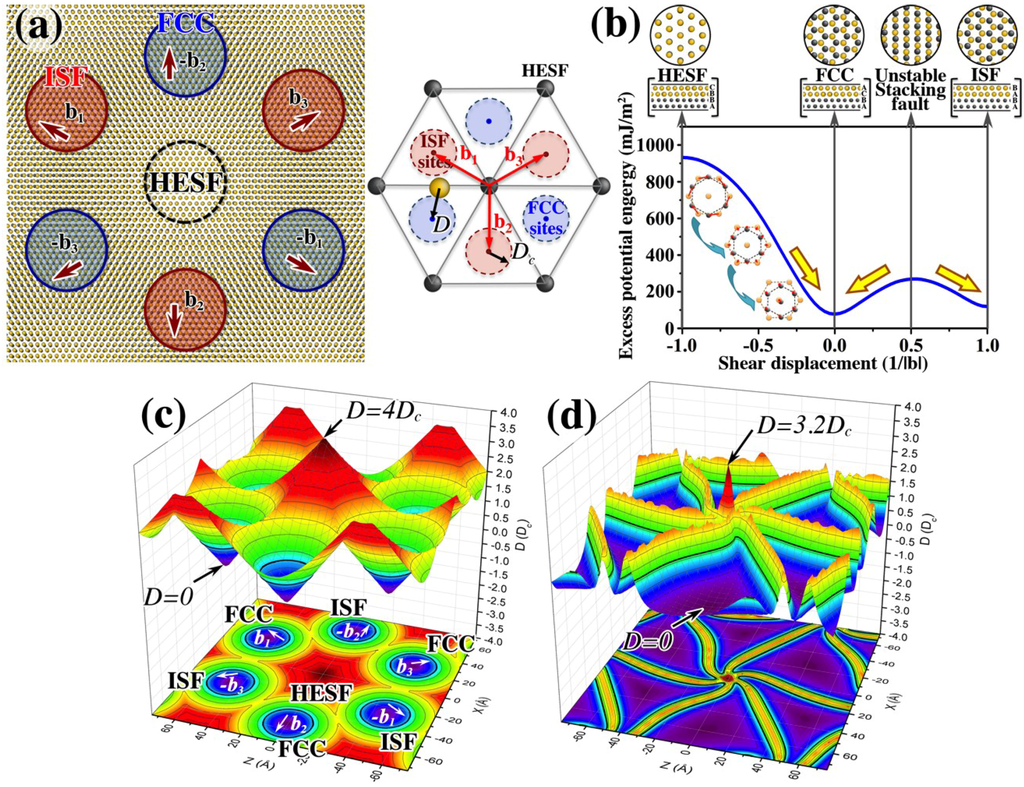
Figure 1.
The relaxation of chemical potential energy in the (111) semi-coherent interface. Demonstrated using the Cu–Ni system. (a) Shows the various local atomic structures of an un-relaxed interface (left) as well as the geometry analysis scheme for the interface (right); (b) shows the generalized stacking fault energy profile corresponding to various local atomic structures at the interface; (c,d) show the contour surface plot according to the geometry analysis of the interface, before and after the relaxation, respectively.
However, the core size of the misfit dislocation, as well as the nodes, cannot shrink to zero. In the relaxed interface, two crystals in the coherent regions (FCC and ISF) are subject to uniform normal strains. Tension develops in the crystal with the smaller lattice parameter and compression in the crystal with the larger lattice parameter. For instance, Figure 2 shows the contour surface plot of the mean strain on the Cu side (larger lattice than Ni) of the interface. In the coherent regions (purple regions), the mean strain is −0.014. Meanwhile, misfit dislocation lines and nodes form between the coherent regions and accommodate the mismatch between the two lattices. Therefore, they feature the opposite stress states—compression in the smaller lattice and tension in the larger lattice. For instance, on Cu side of the interface, the local mean strain is 0.073 at nodes. The misfit dislocation lines and nodes eliminate the uniform normal strains generated by the coherent regions in the crystals away from the interface. Note that before relaxation, the mean strain at the interface is uniformly zero and the local mean strain is introduced solely due to the increase of the interface coherence. The strain amplitude at the misfit dislocations and nodes is dependent on the size of their cores, i.e., the narrower the core, the higher the strain concentration at dislocations and nodes. Therefore, the minimization of the excess potential energy at the interface is counter-balanced by the increase of the strain energy associated with the cores of the misfit dislocation and nodes. In other words, the relaxation of the semi-coherent interface is a completion between the reduction of the interface excess potential energy, and the increase of the strain energy associated with the formation of the misfit dislocation network.
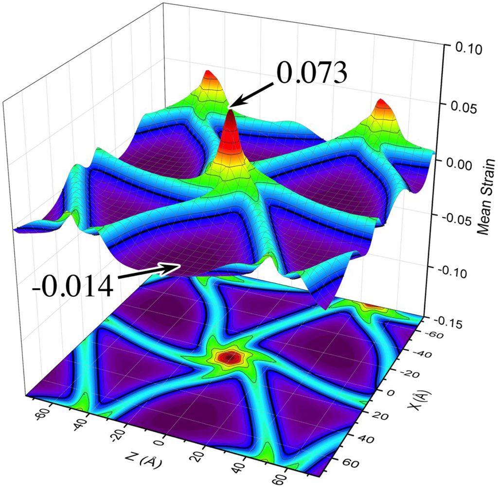
Figure 2.
The contour surface plot of the two-dimensional (x–z) mean strain on the Cu side of the interface. The black lines denote the contour level with zero mean strain.
This argument can easily be verified by observing the dislocation core width when the interface is under biaxial tension and compression conditions. When the interface is subjected to in-plane biaxial tension or compression, the profile of the GSFE changes. Shown in Figure 3a is the GSFE of the (111) Cu–Ni interface with coherent lattice under equilibrium, tension and compression conditions. The GSFE for the tension and compression cases are measured from the coherent Cu–Ni bi-crystals, which assume the lattice constant of Cu and Ni, respectively. The excess potential energies for the key coherent structures, namely HESF, FCC, ISF, and unstable stacking fault, are given in Table 1. Under tension (compression), the excess potential energy for the HESF increases (decreases) while the energies for the FCC, ISF as well as the unstable stacking fault structures decrease (increase). Also the slope of the GSFE profile, which drives the expansion of the Shockley partial loops (black lines in Figure 3b–d), increases (decreases) under this condition. Therefore, compared to the misfit dislocation network under equilibrium conditions, the core of the dislocation and nodes shrinks under tensile loading (Figure 3c) and expands under compressive loading (Figure 3d). For instance, the core size of a node is 1.4 nm under equilibrium; it shrinks to 0.9 nm under tension and expands to 2.4 nm under compression. It is also noted that under compression, the spiral pattern gradually disappears due to the reduced GSFE profile.

Table 1.
Excess potential energy (mJ/m2) for key coherent structures.
| Loading Condition | HESF | FCC | ISF | Unstable SF |
|---|---|---|---|---|
| Tension | 945 | 66 | 110 | 264 |
| Equilibrium | 933 | 78 | 119 | 269 |
| Compression | 924 | 86 | 126 | 273 |
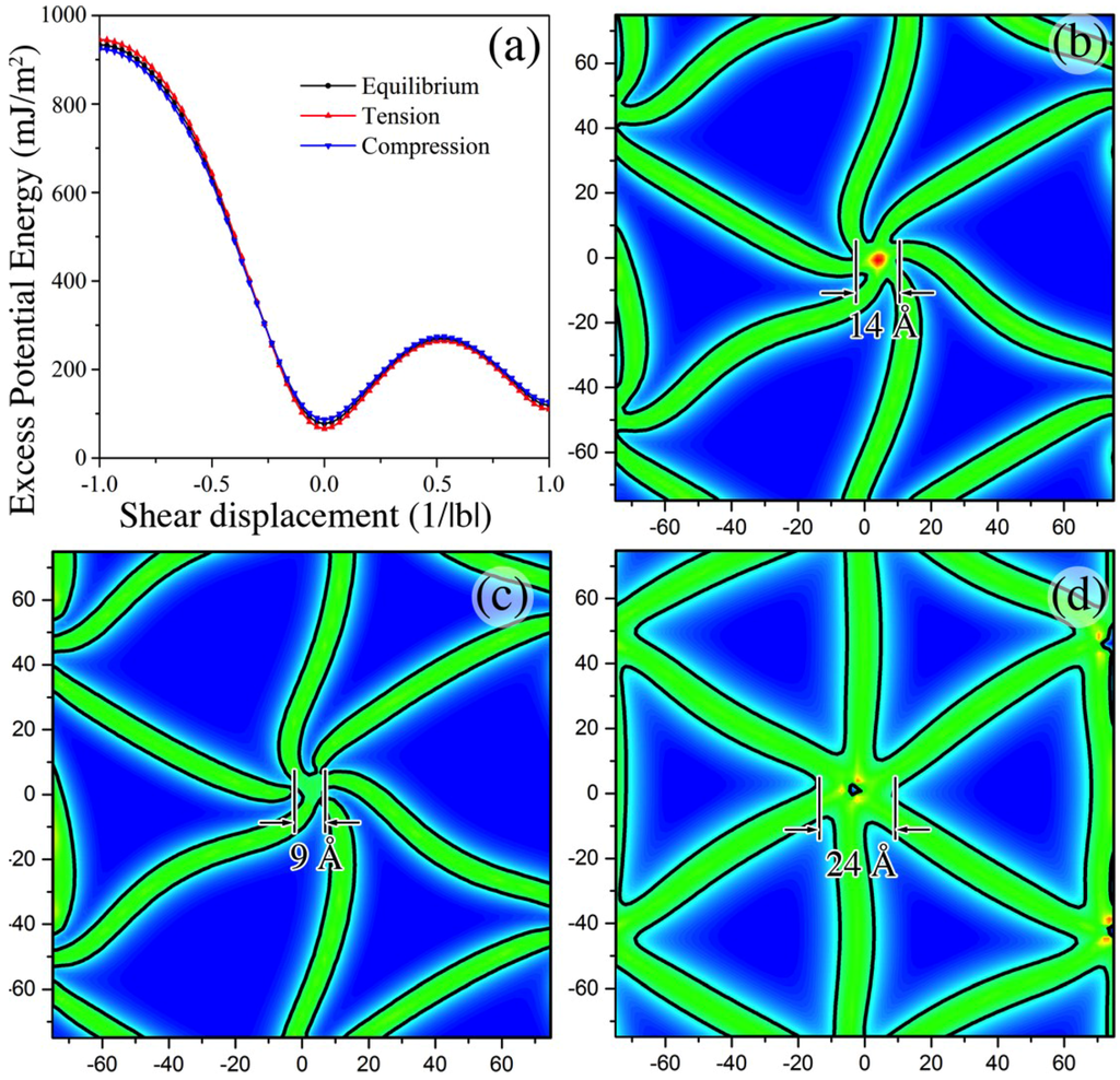
Figure 3.
The variations in the misfit dislocation pattern of the (111) Cu–Ni semi-coherent interface due to loading. (a) shows the variation in the generalized stacking fault energy profile due to loading; (b–d) show the misfit dislocation pattern under equilibrium, tension and compression, respectively.
4. Structures and Properties at Nodes
During the relaxation of the HESF regions, the relative dilatation/compression at the nodes (as illustrated by insets of Figure 1b) creates positive free volume in the larger lattice (Cu) and negative free volume in the smaller lattice (Ni). Under equilibrium conditions, the free volume at node on Cu side is smeared in the vicinity (Figure 4a). The change in core side of the nodes under loading either condenses (under tension), or further smears (under compression) the free volume. Figure 4b shows the condensed free volume at a node on the Cu side of the interface. This type of node has been characterized using dis-registry analysis and the obtained dislocation structure is shown in the inset of Figure 4b. This structure, referred to as the volume-condensed node with “constricted” triangular dislocation structure, has three jogs (green dots) connecting two sets of interfacial dislocations in two adjacent planes: Ni1–Cu1 (blue dislocation lines, between Cu and Ni crystals) and Cu1–Cu2 (green dislocation lines, between the first and second atomic planes in the Cu crystal). The concentrated free volume is regarded as the result of the close clustering of the three jogs, as each of the jogs contains certain free volume. The high strain concentration associated with the condensed free volume at the node on Cu side can be further relaxed via the climb of the jogs along the <110> directions. The resulting structure, referred to as volume-condensed node with “expanded” triangular dislocation pattern, is given in Figure 4c. Such dislocation structures at the node can happen due to the mechanical loading, perturbation, and absorption of interstitials. The triangular nodes can transform into an expanded hexagonal structure (Figure 4d) when it is relaxed at a finite temperature of above 10 K. This structure has been observed in the experiment. This structure, referred to as the volume-condensed node with hexagonal dislocation pattern, is formed from the triangular nodes after a series of complex dislocation reactions (detailed information in [46]). The dislocation structure of the node also involves two adjacent (111) planes (Ni1–Cu1 and Cu1–Cu2). The hexagonal dislocation pattern contains six segmental “superior dislocations” with alternating compositions. (The “superior dislocations” refers to the double-core dislocations formed by two dislocations on the adjacent (111) slip planes.) Three of the dislocations combine perfect-partial dislocations and three others combine partial-partials dislocations. The free volume is localized in the dislocations segments with perfect-partial type (Figure 4d). The net character of the superior dislocations is all pure edge.
As was discussed in the introduction, for interfaces such as the (111) semi-coherent interfaces, the misfit dislocations have widely spread cores and lose the ability of nucleating lattice dislocations. In this case, the nodes always represent a higher stress concentrator and therefore are the primary source for the nucleation of lattice dislocations. The structure of the node therefore has significant impact on the mechanisms for lattice dislocation nucleation.
Under in-plane tension, the volume-smeared nodes with a spiral dislocation pattern (Figure 4a) can transform into volume-condensed nodes with a triangular (Figure 4b,c) pattern. In addition, because the slope of the GSFE profiles increase under tensile loading, the equilibrium distance between the partial misfit dislocations that bound the ISF regions decreases. Therefore, under the influence of thermo fluctuation and tensile stress, the six partial dislocations near a node temporarily recombine and form three perfect dislocation segments (red shaded regions in Figure 5a). The Burgers vectors are , and , respectively. These segments are stronger strain concentrators compared to the partial dislocations and are aligned with the <110> directions. Therefore they act as the sources for the lattice dislocations’ nucleation. All three sources are activated and three equivalent slip systems with Schmid factor of 0.157 are simultaneously triggered (Figure 5c): , , and . After the nucleation and emission of the lattice dislocations, the residual interface dislocation dissociates to form three stair rod dislocations (indicated by red arrows in Figure 5c). The triangular dislocation pattern also disappears after the nucleation. As was reported earlier, if the volume-condensed node with a triangular dislocation pattern is relaxed under a finite temperature of above 10 K, it can transform into a hexagonal pattern. Under biaxial tension, the partial misfit dislocations near nodes also temporarily recombine and form segments of perfect dislocation along <110> directions, which then serve as the nucleation source for lattice dislocations. Similar to the triangular node, all three sources as well as the three equivalent slip systems are activated concurrently. Three stair-rod dislocations (red arrows) are also formed as the result of the nucleation. Unlike the triangular node, the hexagonal dislocation pattern (red shaded area) is preserved even after the nucleation.
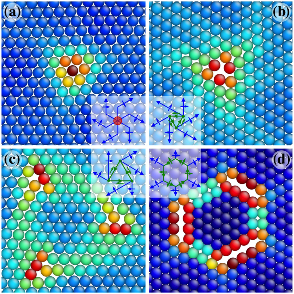
Figure 4.
Various nodal structures associated with the redistribution of free volume, the dislocation structures of nodes are given in the insets. (a) Volume smeared node with spiral dislocation pattern; (b,c) the volume condensed nodes with triangular dislocation pattern; (d) the volume condensed node with hexagonal dislocation pattern.
As was discussed earlier, the transformation of the nodal dislocation structure redistributes the free volume contained in the node. For instance, the volume-smeared node with spiral pattern can jump to the volume-condensed node with triangular dislocation pattern associated with the condensation of the free volume into three jogs. Such rearrangement of the free volume has significant impact on the material’s irradiation properties, such as the point defect formation energies. We have measured the vacancy formation energy (VFE) on both Cu and Ni sides and self-interstitial formation energy (IFE) on Cu side in the vicinity of the nodes. Figure 6 shows the VFE at node on both sides of the interface. Each sphere’s represents an atom in the nodal region; its color (referred to the color scale) is defined by the VFE by removing the atom. As shown by Figure 6a, the VFE at the dislocation cores on Cu side is 1.28 eV, which is closed to the VFE in bulk Cu (1.29 eV). On Ni side (Figure 6b), the VFE at dislocation cores is considerably less than in bulk (1.2 eV vs. 1.51 eV). Due to the hydrostatic compression on the Ni side of the dislocations and nodes, a vacancy formation is favored to happen, which leads to a lower formation energy. The VFE at nodes, while the value on Ni side is still considerably smaller than on Cu side, is significantly less than the bulk values. For a volume-smeared node, the VFE on the Cu and Ni side is 0.95 eV and 0.54 eV (Figure 6a,b), respectively. It is interesting that VFE on the Cu side is 0.34 eV lower than in the bulk although the region is under hydrostatic tension. This is because Ni atom fills in the vacancy site where a Cu atom is removed. Consequently, the elastic strain energy on the Ni side at the node will decrease. For the volume-condensed node with triangular dislocation pattern, the VFE on the Cu side is 0.67 eV when the vacancy is on the compression side of the jog (indicated by dashed ellipses in Figure 6c). This energy is 0.28 eV lower than in the condensed node, associated with the climb of the jogs. When the vacancy is created in the center of the extrinsic stacking fault, the triangular node transforms back into the spiral node associated with a VFE of 0.47 eV. When a vacancy is created on the Ni side of the node (center of Figure 6d), the node always transforms back to the spiral node. The VFE in this case is 0.05 eV. The significant decrease (consistently 0.5 eV) in the VFE for the triangular node compared to the spiral one on both Cu and Ni sides is attributed to structural transformation process of the node from triangular to spiral. The triangular node has a slightly higher energy than the spiral one.
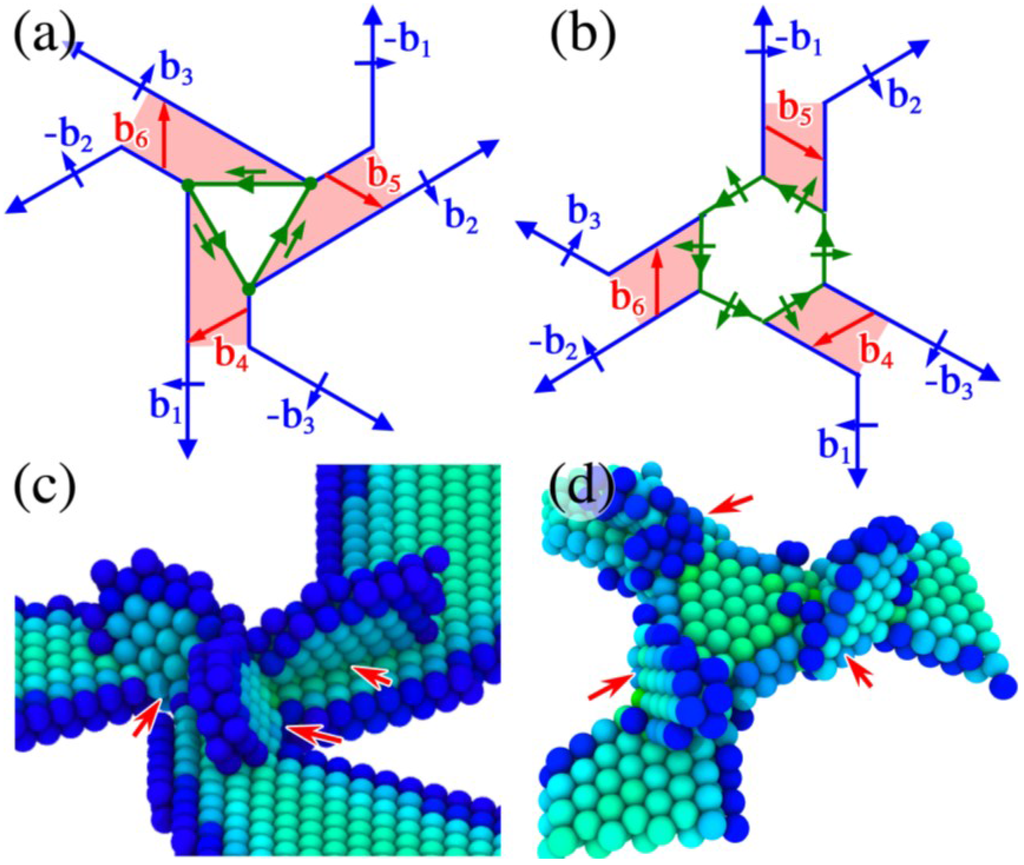
Figure 5.
Mechanisms for lattice dislocation nucleation from the volume condensed nodes with triangular (a,c) and hexagonal (b,d) dislocation patterns. In (a,b), the nucleation sites for the lattice dislocations are marked by the red shaded areas; (c,d) show the dislocation configuration at nodes after the nucleation of dislocations.
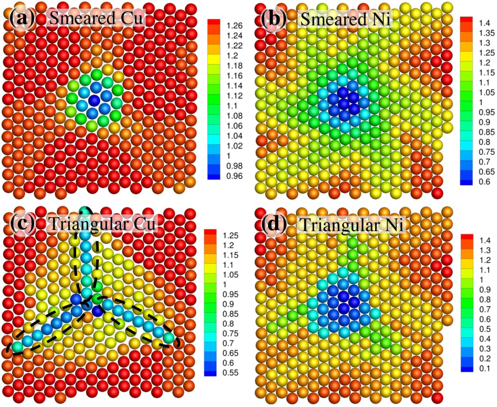
Figure 6.
Mechanisms for lattice dislocation nucleation from the volume condensed nodes with triangular (a,c) and hexagonal (b,d) dislocation patterns. In (a,b), the nucleation sites for the lattice dislocations are marked by the red shaded areas; (c,d) show the dislocation configuration at nodes after the nucleation of dislocations.
Because Ni side of the nodes is under hydrostatic compression, while the Cu side is under hydrostatic compression, our calculation of self-interstitial formation energy (SIFE) is only performed on the Cu side. The SIFE is computed to be −0.14 eV when a Cu atom is embedded into the center of the volume-smeared node with spiral dislocation pattern (Figure 7a dashed circle). This is accompanied by the transformation of the node from spiral to triangular (Figure 7b). For the triangular node, SIFE is around −0.65 eV when a Cu atom is embedded into one of three dislocation jogs (dashed circles in Figure 7c). When three Cu atoms are simultaneously embedded into the three jogs, the average SIFE is −0.62 eV. The expanded node shrinks, accompanying the absorption of Cu interstitials (Figure 7d). The diameter of the expanded node decreases from 2.2 nm to 1.4 nm. The results imply that the expanded node can be a stronger sink for interstitials, as compared with SIFE in the condensed node, and bulk Cu (3.08 eV) and Ni (4.64 eV).
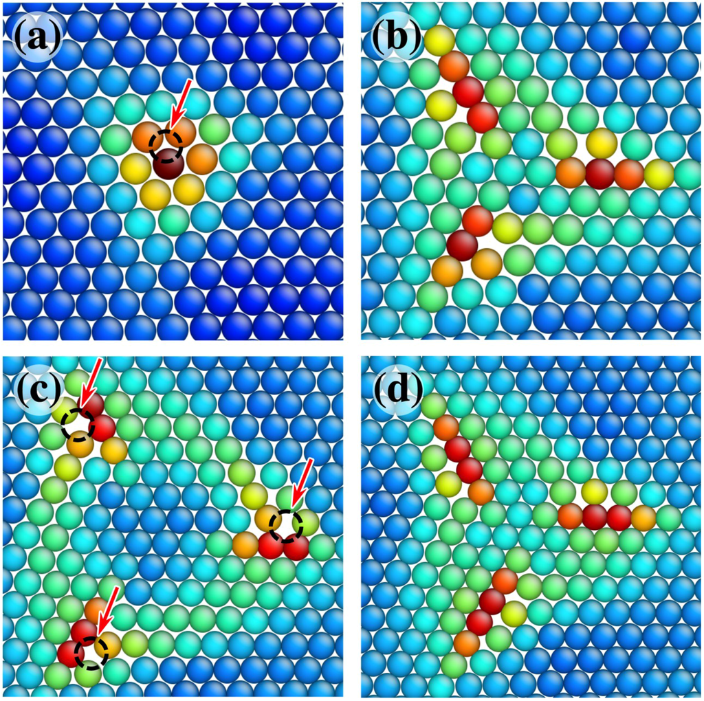
Figure 7.
The structures of self-interstitials at the volume smeared node (a,b) and the volume condensed node with triangular structure (c,d). In (a,b) the structure of the volume smeared node with spiral pattern before and after the insertion of the interstitial in the dashed black circle. In (c,d) the structure of the volume condensed node with triangular dislocation pattern before and after the insertion of a interstitial at one of the jogs (dashed black circles).
5. Discussion and Conclusions
In this work, we studied the energy minimization mechanism of semi-coherent interfaces by performing atomistic simulations and dislocation theory analysis on a Cu–Ni (111) semi-coherent interface as a model system. By examining the GSFE profile of the coherent Cu–Ni interface, two stable structures (FCC and ISF, which correspond to the energy minima on the GSFE curves) and a high-energy structure are identified. Accordingly, the regions containing the stable structures can be treated as the result of the introduction of the partial dislocation loops. The minimization of the chemical potential energy at the interface expands the loop and drives their reaction with each other to form the misfit dislocations. The reduction in the chemical potential energy is achieved at the cost of the increase of core elastic energy of the misfit dislocations. Therefore, the core width of the misfit dislocation and node is dependent on the GSFE profile of the interface. On the other hand, HESF structure is destroyed by undergoing relative twist and dilatation on the two crystals on both sides of the interface, and achieves the near FCC and ISF structure. The relative rotation is responsible for the spiral pattern at nodes, and the relative dilatation is responsible for the formation of free volume at nodes. Under various conditions, the free volume at nodes is redistributed in association with the nodal structural transformation. Under equilibrium, the node assumes a dislocation pattern with smeared free volume. The free volume of this node can condense in association with the transformation to the triangular structure under tensile loading, mechanical perturbation, and addition of interstitials. The triangular node may also transform to the volume-condensed node with hexagonal dislocation pattern when the node is relaxed under a temperature higher than 10 K. The various nodal dislocation structures lead to different nucleation mechanisms for lattice dislocations. Also, associated with the redistribution of the free volume, the different nodal structures also have significantly different point defect formation energies.
Although this work only presents the investigation of the relaxation of the Cu–Ni (111) semi-coherent interface, the approach adopted in this work to qualitatively predict the interface structures as well as interface relaxation mechanisms discovered here is applicable to other semi-coherent interfaces as well. However, according relaxation mechanisms we discovered in this work, the various features demonstrated by the node in the Cu–Ni interface, such as various dislocation nucleation mechanisms and different point defect formation energies associated with the various node structures, as well as the spiral pattern at nodes, are not always the case for other FCC semi-coherent interfaces. For instance, we have inspected the structures two types of interfaces: I. twist boundary in FCC single crystals (Cu, Ag and Al), II. the Cu–Ag (111) semi-coherent interface (13% lattice mismatch). We found that both nodal structural transformation and the spiral pattern disappear in the two types of interface. The twist boundaries’ interface dislocations are all pure screw-type, and the nodes are subject to zero tension and compression, therefore there is not free volume created in the nodes. This removes the driving force for the nodal structural transformation associated with the redistribution of free volume. Also the atoms in the node region have already occupied near low-energy sites (i.e., FCC and ISF), therefore the spiral pattern is not necessary. On the other hand, the larger lattice mismatch between Cu and Ag dictates a much smaller interface nodal spacing (2.2 nm in Cu–Ag vs. 9.5 nm in Cu–Ni). The increase in interaction energy due to the spiral pattern surpasses reduction in the self-energy of the node and dislocation. Therefore, the spiral pattern does not appear in Cu–Ag interface. In addition, the structural transformation of a node requires certain space. For instance, the volume-condensed node with triangular dislocation pattern as depicted in Figure 4c has a diameter of 2.2 nm, which is equal to the nodal spacing in the Cu–Ag interface. In this case, the significantly high repulsion between the jogs from adjacent nodes will suppress the nodal structural transformation. Therefore, the nodal features of the semi-coherent interfaces are subject to on the node spacing which, in turn, is ultimately dependent on the lattice mismatch and lattice rotation.
Acknowledgments
S.S. and J.W. acknowledge the support provided by the U.S. Department of Energy, Office of Science, Office of Basic Energy Sciences. S.S. also thanks the support provided by the Center for Materials at Irradiation and Mechanical Extremes, an Energy Frontier Research Center funded by the U.S. Department of Energy, Office of Science, Office of Basic Energy Sciences under Grant No. 2008LANL1026. S.S and J.W. also acknowledge support provided by the Los Alamos National Laboratory Directed Research and Development (LDRD-ER20140450). J.W. also acknowledges the Start-up provided by the University of Nebraska-Lincoln. The valuable discussion with J.P. Hirth, Richard G. Hoagland, and Robert Pond is appreciated.
Author Contributions
S.S. performed MD simulations and wrote the first draft of the manuscript. J.W. designed this project, performed the calculation for generalized stacking fault energies. All authors finalized the manuscript.
Conflicts of Interest
The authors declare no conflict of interest.
References
- Howe, J.M.; Pond, R.C.; Hirth, J.P. The role of disconnections in phase transformations. Prog. Mater. Sci. 2009, 54, 792–838. [Google Scholar] [CrossRef]
- Frank, F.C. Martensite. Acta Metall. 1953, 1, 15–21. [Google Scholar] [CrossRef]
- Bilby, B.A.; Bullough, R.; Smith, E. Continuous Distributions of Dislocations: A New Application of the Methods of Non-Riemannian Geometry. Proc. R. Soc. Lond. A 1955. [Google Scholar] [CrossRef]
- Bullough, R. The dislocation content of a large angle tilt boundary. Philos. Mag. 1965, 12, 1139–1141. [Google Scholar] [CrossRef]
- Hirth, J.P.; Balluffi, R.W. On grain boundary dislocation and ledges. Acta Metall. 1973, 21, 929–942. [Google Scholar] [CrossRef]
- Pond, R.C.; Vlachavas, D.S. Bicrystallophraphy. Proc. R. Soc. Lond. A 1983. [Google Scholar] [CrossRef]
- Mitlin, D.; Misra, A.; Mitchell, T.E.; Hirth, J.P.; Hoagland, R.G. Interface dislocation structures at the onset of coherency loss in nanoscale Ni–Cu bilayer films. Philos. Mag. 2004, 85, 3379–3392. [Google Scholar] [CrossRef]
- Liu, Y.; Bufford, D.; Wang, H.; Sun, C.; Zhang, X. Mechanical properties of highly textured Cu/Ni multilayers. Acta Mater. 2011, 59, 1924–1933. [Google Scholar] [CrossRef]
- Liu, Y.; Bufford, D.; Rios, S.; Wang, H.; Chen, J.; Zhang, J.Y.; Zhang, X. A formation mechanism for ultra-thin nanotwins in highly textured Cu/Ni multilayers. J. Appl. Phys. 2012. [Google Scholar] [CrossRef]
- Hirth, J.P.; Pond, R.C.; Hoagland, R.G.; Liu, X.Y.; Wang, J. Interface defects, reference spaces and the Frank-Bilby equation. Prog. Mater. Sci. 2013, 58, 749–823. [Google Scholar] [CrossRef]
- Misra, A; Hirth, J.P.; Kung, H. Single-dislocation-based strengthening mechanisms in nanoscale metallic multilayers. Philos. Mag. 2002, 82, 2935–2951. [Google Scholar]
- Wang, J.; Misra, A. Strain hardening in nanolayered thin films. Curr. Opin. Solid State Mater. Sci. 2014, 18, 19–28. [Google Scholar] [CrossRef]
- Misra, A.; Hirth, J.P.; Hoagland, R.G. Length-scale-dependent deformation mechanisms in incoherent metallic multilayered composites. Acta Mater. 2005, 53, 4817–4824. [Google Scholar] [CrossRef]
- Li, N.; Wang, J.; Misra, A.; Huang, J.Y. Direct obervations of confined layer slip in Cu/Nb multilayers. Microsc. Microanal. 2012, 18, 1155–1162. [Google Scholar] [CrossRef] [PubMed]
- Anderson, P.M.; Foecke, T.; Hazzledine, P.M. Dislocation-based deformation mechanisms in metallic nanolaminates. MRS Bull. 1999, 24, 27–33. [Google Scholar]
- Li, Q.; Anderson, P.M. Dislocation-based modeling of the mechanical behavior of epitaxial metallic multilayer thin films. Acta Mater. 2005, 53, 1121–1134. [Google Scholar] [CrossRef]
- Carpenter, J.S.; Misra, A.; Anderson, P.M. Achieving maximum hardness in semi-coherent multilayer thin films with unequal layer thickness. Acta Mater. 2012, 60, 2625–2636. [Google Scholar] [CrossRef]
- Shao, S.; Zbib, H.M.; Mastorakos, I.; Bahr, D.F. Effect of interfaces in the work hardening of nanoscale multilayer metallic composites during nanoindentation: A molecular dynamics investigation. J. Eng. Mater. Technol. 2013. [Google Scholar] [CrossRef]
- Shao, S.; Zbib, H.M.; Mastorakos, I.; Bahr, D.F. Deformation mechanisms, size effects, and strain hardening in nanoscale metallic multilayers under nanoindentation. J. Appl. Phys. 2013. [Google Scholar] [CrossRef]
- Wang, J.; Hoagland, R.G.; Liu, X.Y.; Misra, A. The influence of interface shear strength on the glide dislocation-interface interactions. Acta Mater. 2011, 59, 3164–3173. [Google Scholar] [CrossRef]
- Wang, J.; Hoagland, R.G.; Hirth, J.P.; Misra, A. Atomistic simulations of shear strength and sliding mechanisms of copper-niobieum interfaces. Acta Mater. 2008, 56, 3109–3119. [Google Scholar] [CrossRef]
- Wang, J.; Hoagland, R.G.; Hirth, J.P.; Misra, A. Atomistic modeling of the interaction of glide dislocations with “weak” interfaces. Acta Mater. 2008, 56, 5685–5693. [Google Scholar] [CrossRef]
- Misra, A.; Demkowicz, M.J.; Wang, J.; Hoagland, R.G. The multiscale modeling of plastic deformation in metallic nanolayered composites. JOM 2008, 60, 39–42. [Google Scholar] [CrossRef]
- Anderson, P.M.; Li, Z. A Peiers analysis of the critical stress for transmission of a screw dislocation across a coherent, sliding interface. Mater. Sci. Eng. A 2001, 319–321, 182–187. [Google Scholar] [CrossRef]
- Shen, Y.; Anderson, P.M. Transmission of a screw dislocation across a coherent, non-slipping interface. J. Mech. Phys. Solids 2007, 55, 956–979. [Google Scholar] [CrossRef]
- Wang, J.; Zhang, R.F.; Zhou, C.Z.; Beyerlein, I.J.; Misra, A. Interface dislocation patterns and dislocation nucleation in face-centered-cubic and body-centered-cubic bi-crystal interfaces. Int. J. Plast. 2014, 53, 40–55. [Google Scholar] [CrossRef]
- Zhang, R.F.; Wang, J.; Beyerlein, I.J.; Germann, T.C. Dislocation nucleation mechanisms from fcc/bcc incoherent interfaces. Scr. Mater. 2011, 65, 1022–1025. [Google Scholar] [CrossRef]
- Zhang, R.F.; Wang, J.; Beyerlein, I.J.; Misra, A.; Germann, T.C. Atomic-scale study of nucleation of dislocations from fcc-bcc interfaces. Acta Mater. 2012, 60, 2855–2865. [Google Scholar] [CrossRef]
- Beyerlein, I.J.; Wang, J.; Zhang, R.F. Interface-dependent nucleation in nanostructured layered composites. APL Mater. 2013. [Google Scholar] [CrossRef]
- Beyerlein, I.J.; Wang, J.; Zhang, R.F. Mapping dislocation nucleation behavior from bimetal interfaces. Acta Mater. 2013, 61, 7488–7499. [Google Scholar] [CrossRef]
- Wang, J.; Zhou, C.Z.; Beyerlein, I.J.; Shao, S. Modeling interface-dominated mechanical behavior of nanolayered crystalline composites. JOM 2014, 66, 102–113. [Google Scholar] [CrossRef]
- Shao, S.; Wang, J.; Misra, A.; Hoagland, R.G. Spiral patterns of dislocations at nodes in (111) semi-coherent FCC interfaces. Sci. Rep. 2013. [Google Scholar] [CrossRef] [PubMed]
- Di, Z.F.; Bai, X.M.; Wei, Q.M.; Won, J.H.; Hoagland, R.G.; Wang, Y.Q.; Misra, A.; Uberuaga, B.P.; Nastasi, M. Tunable helium bubble superlattice ordered by screw dislocation network. Phys. Rev. B 2011. [Google Scholar] [CrossRef]
- Li, N.; Wang, J.; Wang, Y.Q.; Serruyz, Y.; Nastasi, M.; Misra, A. Incoherent twin boundary migration induced by ion irradiation in Cu. J. Appl. Phys. 2013. [Google Scholar] [CrossRef]
- Rose, M.; Balogh, A.G.; Hahn, H. Instability of irradiation induced defects in nanostructured materials. Nucl. Instrum. Meth. Phys. Res. B 1997, 127–128, 119–122. [Google Scholar] [CrossRef]
- Chimi, Y.; Iwase, A.; Ishikawa, N.; Kobiyama, M.; Inami, T.; Okuda, S. Accumulation and recovery of defects in ion-irradiated nanocrystalline gold. J. Nucl. Mater. 2001, 297, 355–357. [Google Scholar] [CrossRef]
- Martínez, E.; Caro, A. Atomistic modeling of long-term evolution of twist boundaries under vacancy supersaturation. Phys. Rev. B 2012. [Google Scholar] [CrossRef]
- Martínez, E.; Hirth, J.P.; Nastasi, M.; Caro, A. Structure of a 2 degrees (010) Cu twist boundary interface and the segregation of vacancies and He atoms. Phys. Rev. B 2012. [Google Scholar] [CrossRef]
- Kolluri, K.; Demkowicz, M.J. Formation, migration, and clustering of delocalized vacancies and interstitials at a solid-state semicoherent interface. Phys. Rev. B 2012. [Google Scholar] [CrossRef]
- Mishin, Y.; Mehl, M.J.; Papaconstantopoulos, D.A.; Voter, A.F.; Kress, J.D. Structural stability and lattice defects in copper: Ab initio, tight-binding, and embedded-atom calculations. Phys. Rev. B 2001. [Google Scholar] [CrossRef]
- Voter, A.F.; Chen, S.P. Accurate Interatomic Potentials for Ni, Al and Ni3Al. Mater. Res. Soc. Symp. Proc. 1987, 82, 175–180. [Google Scholar] [CrossRef]
- Bonny, G.; Pasianot, R.C.; Castin, N.; Malerba, L. Ternary Fe–Cu–Ni many-body potential to model reactor pressure vessel steels: First validation by simulated thermal annealing. Philos. Mag. 2009, 89, 3531–3546. [Google Scholar] [CrossRef]
- Shao, S.; Wang, J.; Misra, A. Energy minimization mechanisms of semi-coherent interfaces. J. Appl. Phys. 2014. [Google Scholar] [CrossRef]
- Salehinia, I.; Shao, S.; Wang, J.; Zbib, H.M. Interface structure and the inception of plasticity in Nb/NbC nanolayered composites. Acta Mater. 2015, 86, 331–340. [Google Scholar] [CrossRef]
- Shao, S.; Wang, J.; Misra, A.; Hoagland, R.G. Relaxation of misfit dislocation at nodes. Mater. Sci. Forum 2014, 783–786, 515–520. [Google Scholar] [CrossRef]
- Shao, S.; Wang, J.; Beyerlein, I.J.; Misra, A. Glide dislocation nucleation from dislocation nodes at semi-coherent {111} Cu–Ni interfaces. Acta Mater. 2015, 98, 206–220. [Google Scholar] [CrossRef]
© 2015 by the authors; licensee MDPI, Basel, Switzerland. This article is an open access article distributed under the terms and conditions of the Creative Commons Attribution license (http://creativecommons.org/licenses/by/4.0/).