3.1. Cooling Curves and Microstructures of Ductile Cast Iron
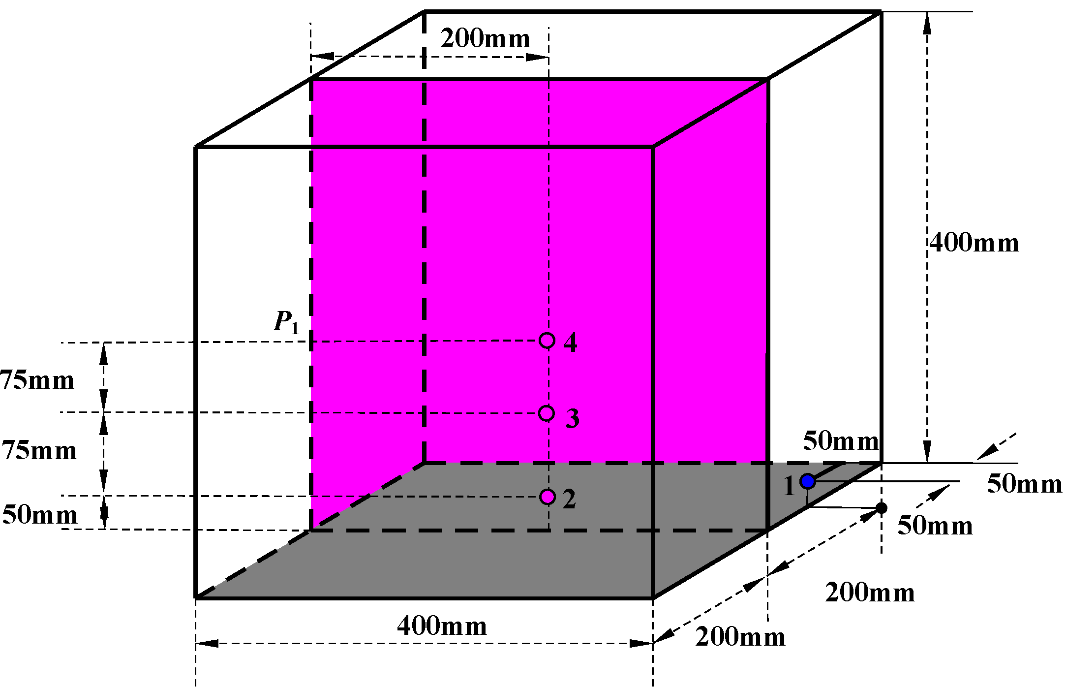
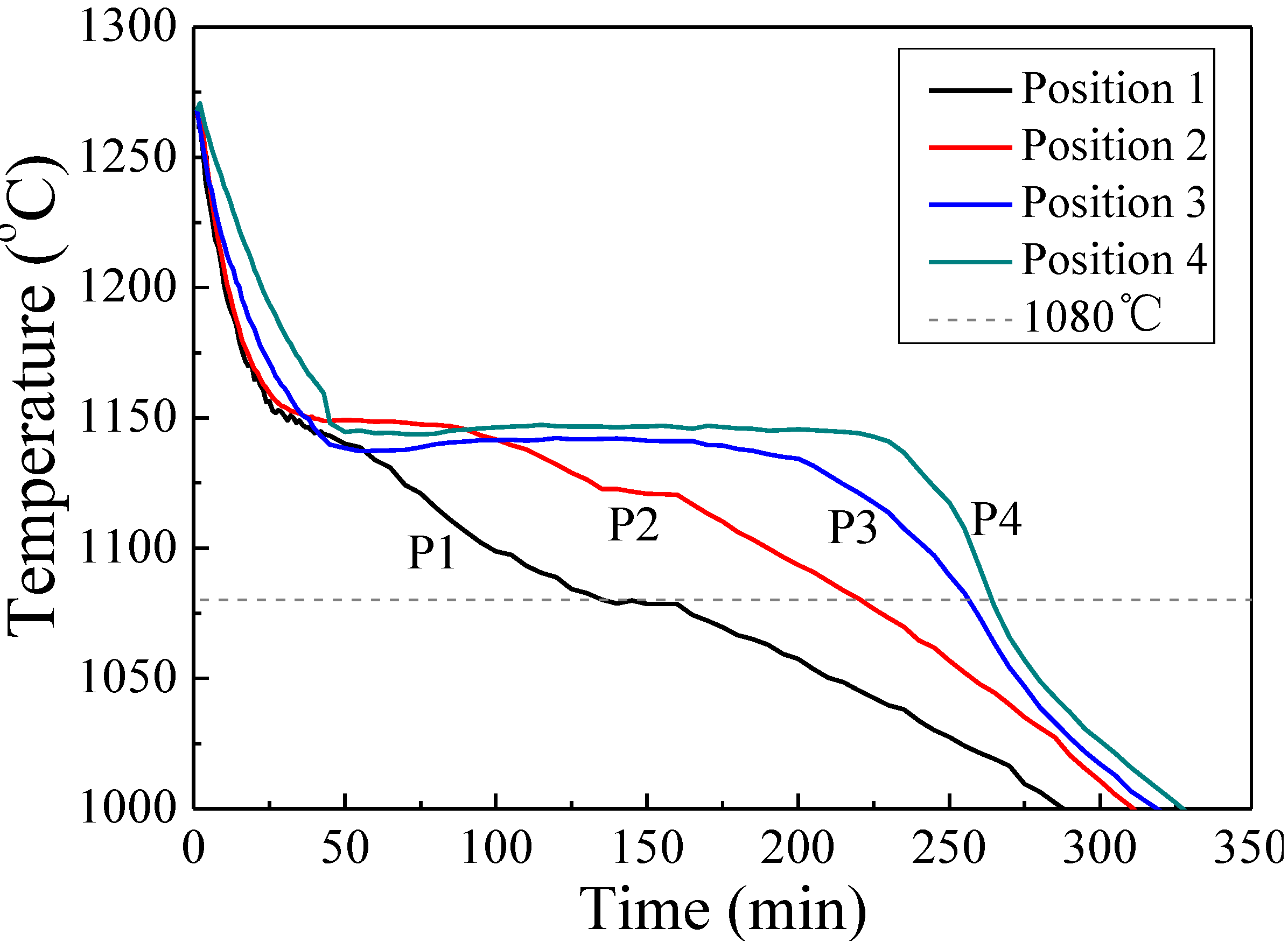
Figure 4 shows the cooling curves at four positions of two castings during solidification. It can be seen that the cooling rate at position 1 is the highest and the subsequent sequence is positions 2, 3, and 4. At position 3 and position 4, the solidification time is more than 250 min. The cooling curves in
Figure 4 represent the cooling rate of four positions in two castings owing to the micro-amount change of Si content. The influence of Si content on the cooling process of ductile iron (more than 500 kg) can be ignored [
15].
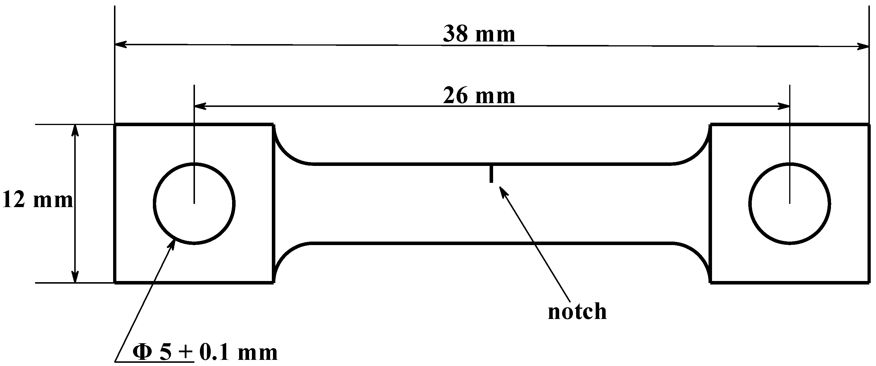
Figure 2.
Dimensions of the fracture toughness specimen.
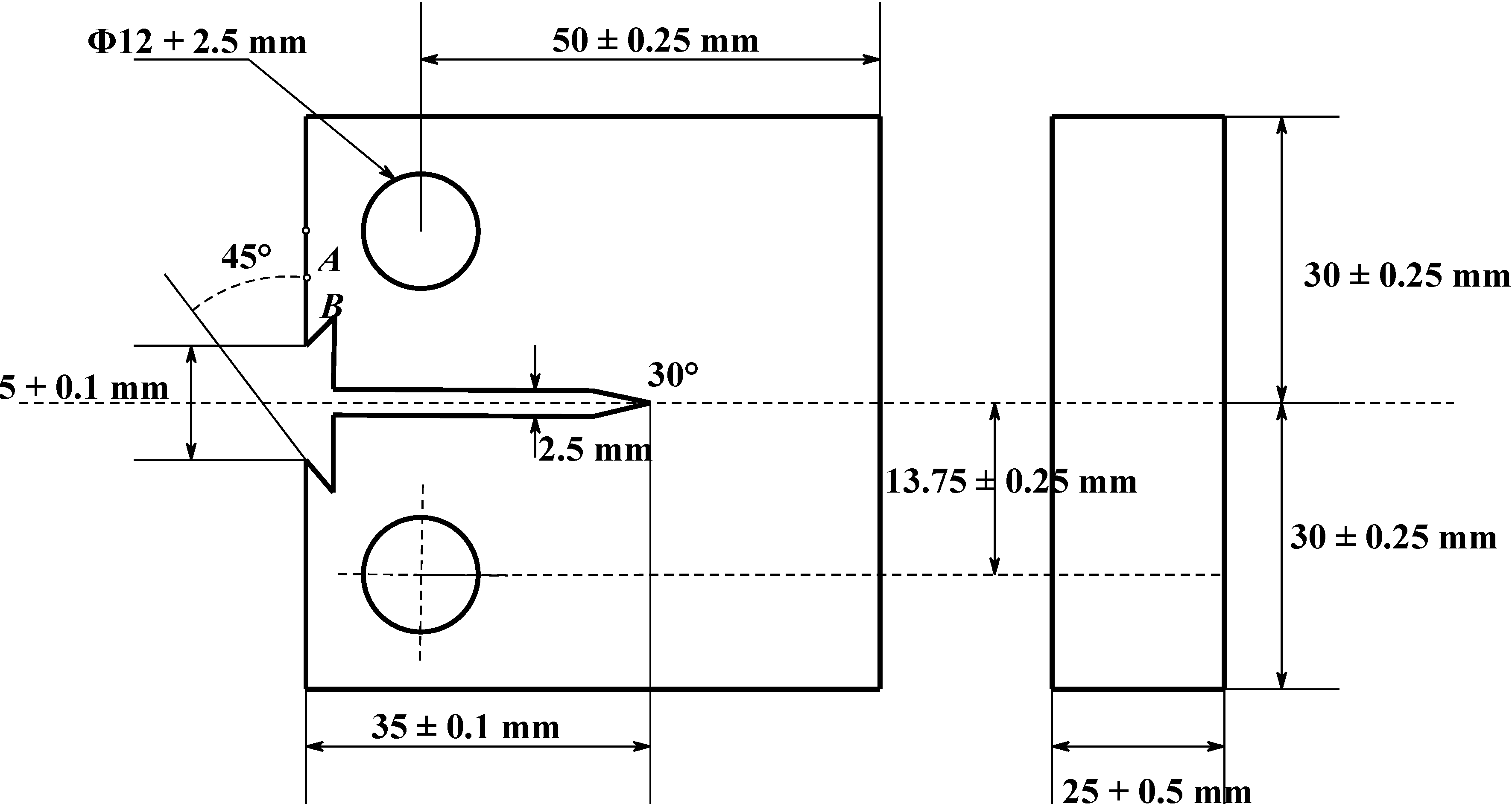
Figure 3.
Dimensions of the in situ SEM tensile specimen.
Figure 4.
Cooling curves at four positions of castings during solidification.
The OM observation results show that the matrix structure of all specimens contains ferrite without pearlite.
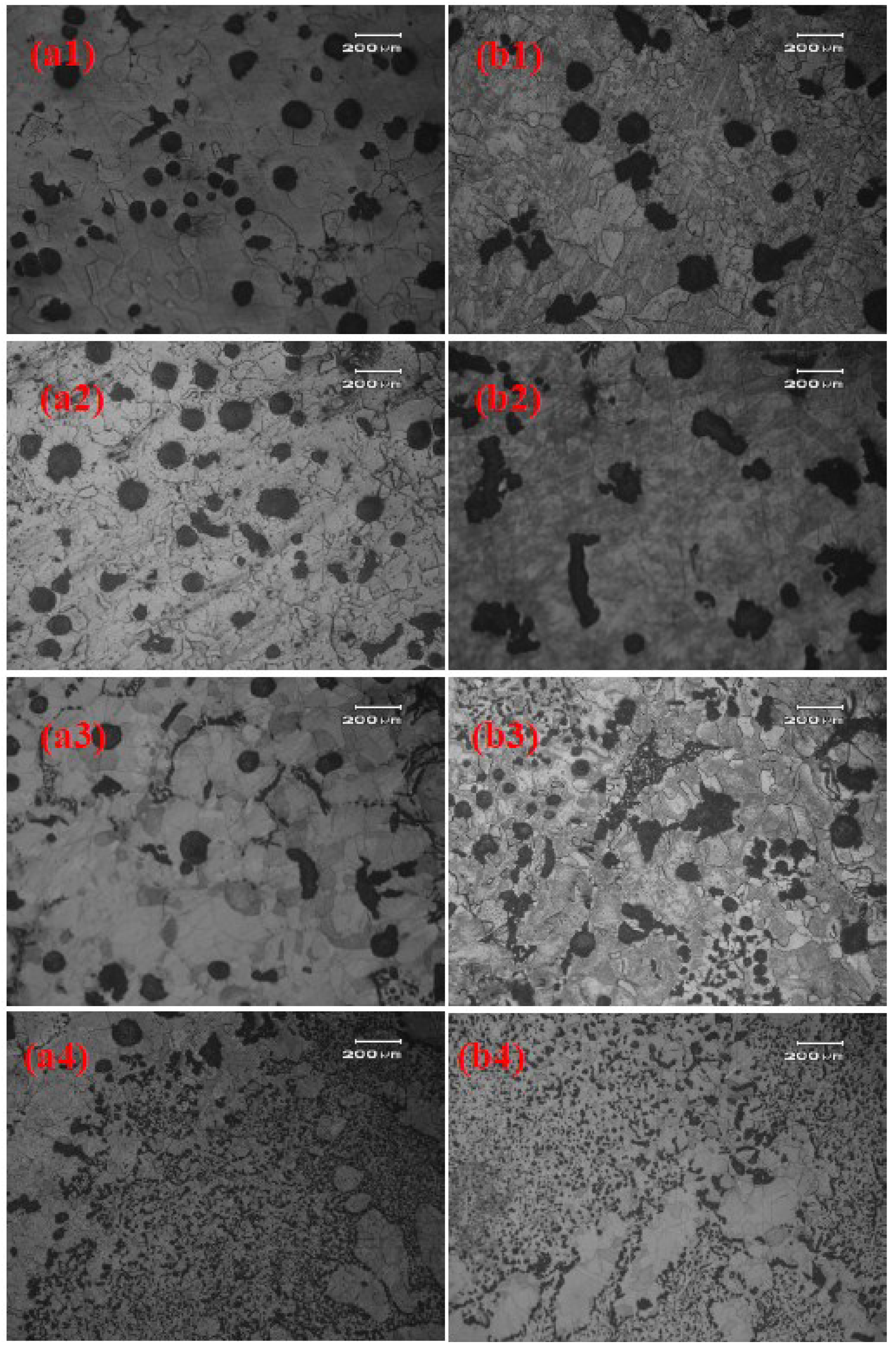
Figure 5 shows the graphite morphology of specimens at four positions of Casting-A (Si content of 1.78 wt.%) and Casting-B (Si content of 2.74 wt.%), respectively. As shown in
Figure 5a1, the graphite nodules are almost spheroidal and a small amount of quasi-spheroidal temper graphite can be observed at position 1 of casting-A. With the increase of solidification time, the quasi-spheroidal temper graphite nodule and temper graphite nodule increases, as shown in
Figure 5a2. With the further increase of solidification time, some vermicular graphite nodules occur, as shown in
Figure 5a3. It shows that the spheroidalization decaying happens in Casting-A. The graphite nodules are almost chunky and the graphite is tempered at position 4 of casting-A, as shown in
Figure 5a4. It can be inferred that with the decrease of cooling rate, the spheroidalization decaying becomes more significant and the graphite morphology gradually deteriorates.
Figure 5.
Graphite morphology of at four positions of two castings (a1) specimen A1; (a2) specimen A2; (a3) specimen A3; (a4) specimen A4; (b1) specimen B1; (b2) specimen B2; (b3) specimen B3; and (b4) specimen B4.
As shown in
Figure 5b1, the graphite nodules at position 1 of casting-B are almost that of spheroidal and quasi-spheroidal temper graphite, and some temper graphite can be observed. With the decrease of cooling rate, the number and diameter of graphite nodules of specimen B2 decreases. Some vermicular graphite can be observed at position 2, as shown in
Figure 5b2. The graphite morphology of specimens B3 and B4 is almost that of chunky, vermicular graphite. It can be inferred that significant spheroidalization decaying occurs, as shown in
Figure 5b3,b4. The morphology of graphite, graphite sphere grade and nodularity of the specimens in Casting-A and Casting-B are listed in
Table 3. It can be seen that the graphite sphere grade and nodularity of Casting-A are higher than that of Casting-B at the same position.
The silicon, like cerium, calcium and nickel, can cause melting point of austenitic shell to drop and promote the formation of chunky graphite. Therefore, the content of silicon must be controlled in the production of heavy-section ductile cast iron. Generally, a suitable addition of silicon can obviously improve the graphite sphere grade and nodularity of heavy section ductile iron [
9]. However, when the content is 2.74 wt.%, the aggregation of chunky graphite occurs, as shown in
Figure 5b4. This is because the excess addition of Si will result in too much heterogeneous nucleation, causing an increase in the amount of chunky graphite and the aggregation of chunky graphite. Areas of aggregation become weak points during tensile and impact tests [
16,
17].
Table 3.
Morphology of graphite, graphite sphere grade and nodularity in Casting-A (Si content = 1.78 wt.%) and Casting-B (Si content = 2.74 wt.%).
| Specimens | Graphite Morphology | Graphite-sphere Grade | Nodularity% |
|---|
| A1 | Spheroidal + Quasi-spheroidal temper | 3 | 80 |
| A2 | Spheroidal + Quasi-spheroidal temper + temper | 5 | 60 |
| A3 | Spheroidal + Temper + Vermicular | 6 | 50 |
| A4 | Spheroidal + Temper + chunky | - | - |
| B1 | Spheroidal+Quasi-spheroidal temper + temper | 5 | 60 |
| B2 | Spheroidal + Temper + Vermicular | 6 | 50 |
| B3 | Temper + Vermicular + chunky | - | - |
| B4 | Vermicular + Temper + chunky | - | - |
3.2. Mechanical Properties of Ductile Cast Iron
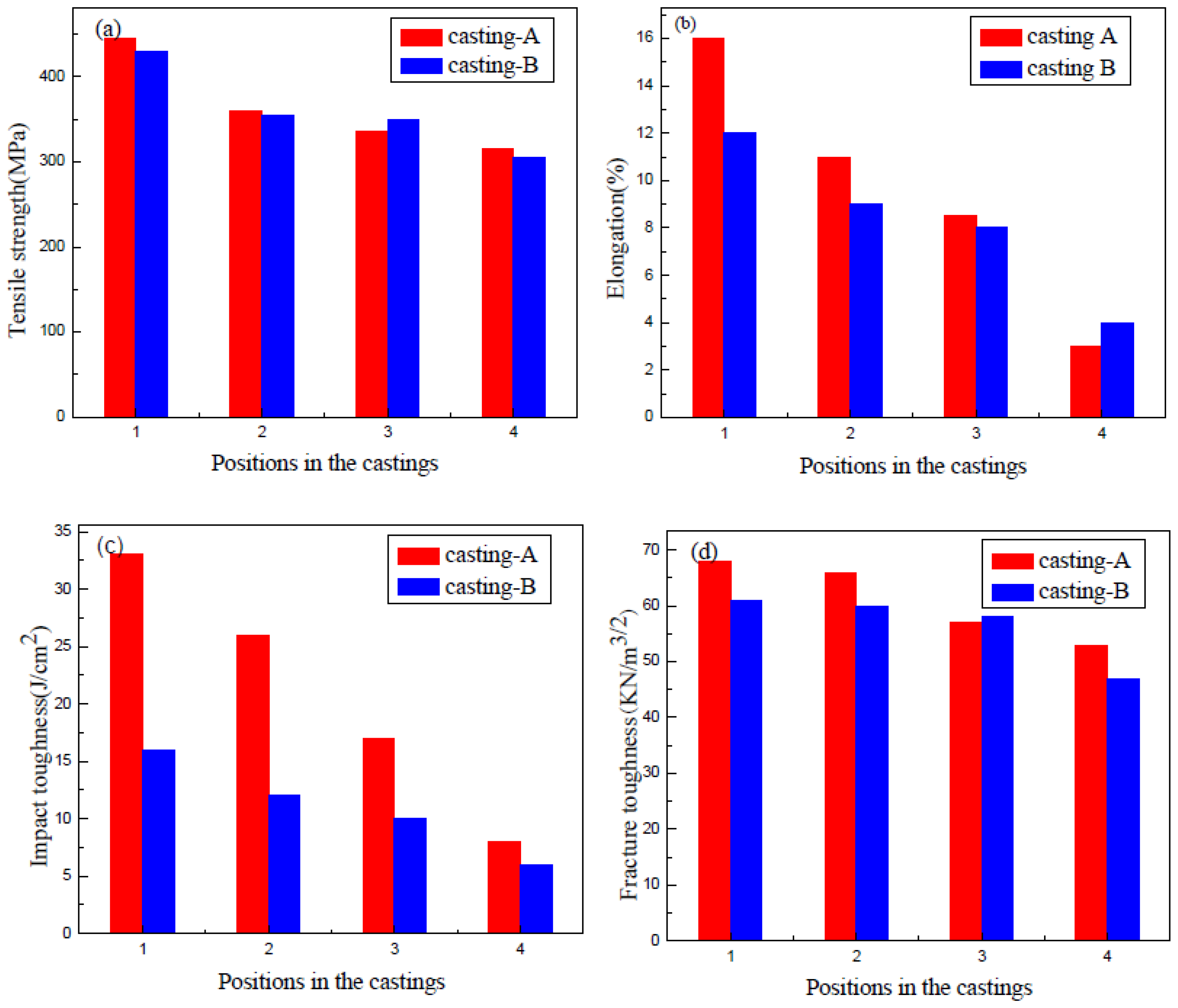
Figure 6 shows the tensile strength, impact toughness, elongation and fracture toughness of the specimens at the four positions of Casting-A and Casting-B. With the decrease of the cooling rate, the mechanical properties of ductile iron decrease. The mechanical properties of the specimens at position 4 of the two castings are the poorest. Compared with the specimen at position 1 of Casting-A, the tensile strength, impact toughness, elongation and fracture toughness of the specimens at position 4 are decreased by 6.7%, 75.8%, 81.3% and 28.3%, respectively. As for Casting-B, compared with the specimen at position 1, the tensile strength, impact toughness, elongation and fracture toughness of the specimens at position 4 are decreased by 5.8%, 62.5%, 66.7% and 29.8%, respectively.
Figure 6.
The tensile strength, elongation, impact toughness and fracture toughness at four positions of two castings (a) Tensile strength; (b) Elongation; (c) Impact toughness; and (d) Fracture toughness.
As shown in
Figure 6, it can be seen that the mechanical properties of the Casting-A is higher than that of Casting-B at the same position. With the increase of Si content, the mechanical properties of heavy section ductile iron decrease. This is because Si can increase the eutectic temperature, reduce the carbon content of the eutectic ferrite and increase the amount of ferrite. However, Si is an extremely sensitive element in heavy section ductile iron, and the excess of it can result in the generation of chunky graphite [
17].
3.3. Fracture Microstructure
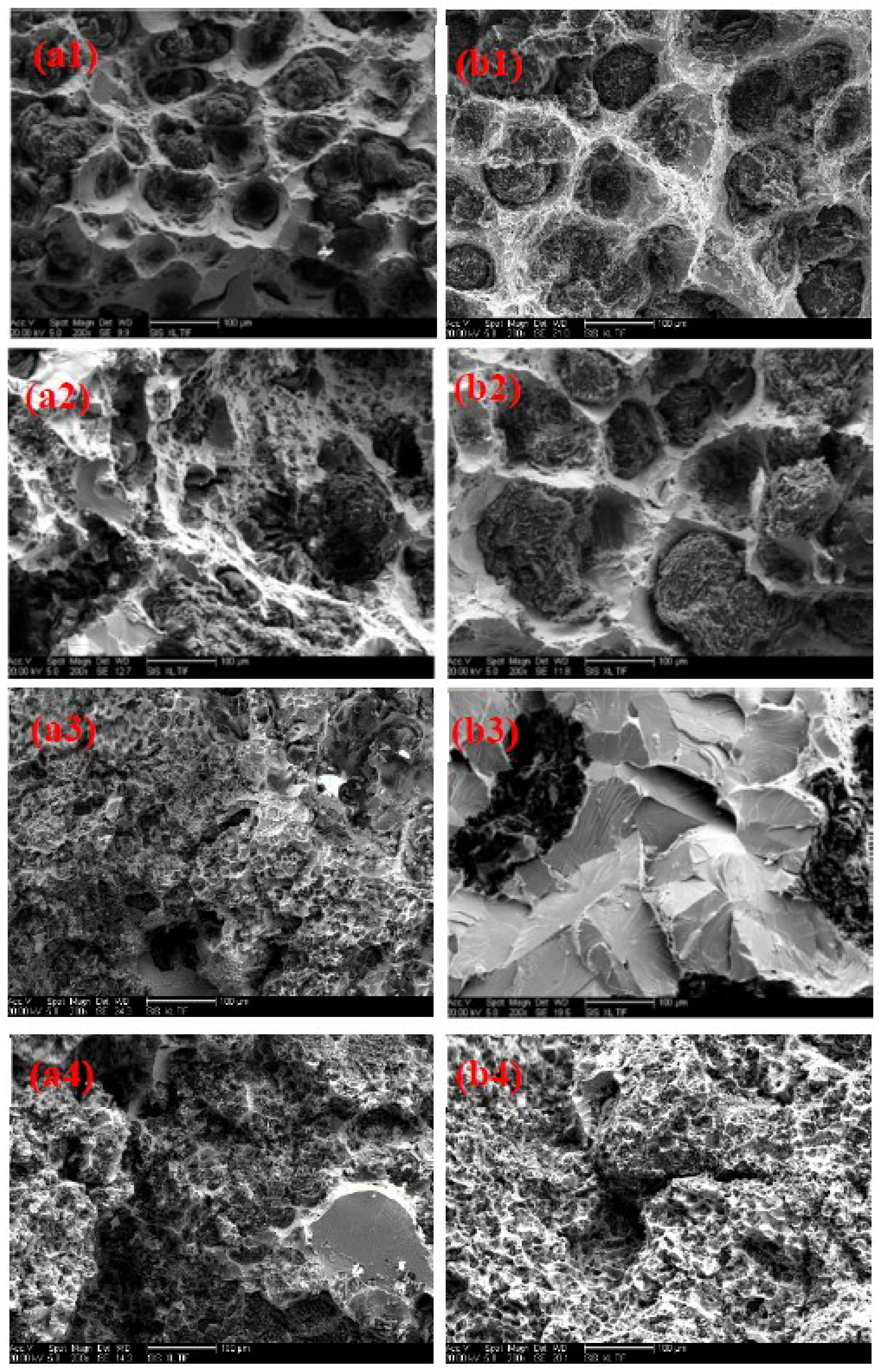
Figure 7 shows the fracture toughness fracture microstructures of the specimens in Casting-A and Casting-B. As shown in
Figure 7a, there are many dimples in the matrix at position 1 of casting-A. The graphite nodules are surrounded by dense dimples, forming tearing ridges. Most of the tearing ridges are closed. The closed tearing ridges can retard the spread of micro-cracks and the connections between the cracks. Therefore, the specimen A1 shows better ductility. The graphite nodules being peeled off from the ferrite under applied force creates the fracture mechanism. The cavities are formed and grow under the effect of slip. Eventually, the cavities connect with each other and cause macroscopic fracture. A relatively larger plastic deformation of ferrite is generated during this process. The fracture morphology of specimen A1 is a typical ductile fracture.
As shown in
Figure 7a2,b1, there exists a small amount of dimples in the matrix. Some tearing ridges are connected with each other. A few graphite nodules are split by the spread of micro-cracks that originate from the adjacent abnormal graphite, such as temper graphite and vermicular graphite. The fracture morphology of specimen A2 and specimen B1 is the mixed cleavage-dimple fracture. There are some abnormal graphite nodules in specimen A3 and B2, as shown in
Figure 7a3,b2. When the force is applied on the specimens, stress concentration forms at the tips of the abnormal graphite, and micro-cracks originate at these places. The micro-cracks quickly reach an unstable spreading stage without experiencing a cavity aggregation growth stage due to high stress concentration at the tips of abnormal graphite and inconsistency in the deformation performance of ferrite. Most of the graphite nodules are fractured because they cannot be protected by the dimples. Cracks spread quickly in the ferrite, causing cleavage fracture with flat cleavage planes. The fracture morphology of specimens A3 and B2 shows brittle fracture of the cleavage.
Figure 7.
The fracture toughness fracture morphology at four positions of two castings (a1) specimen A1; (a2) specimen A2; (a3) specimen A3; (a4) specimen A4; (b1) specimen B1; (b2) specimen B2; (b3) specimen B3; and (b4) specimen B4.
As shown in
Figure 7a4,b3,b4, there is a large amount of small cleavage planes. The aggregation of chunky graphite occurs. The stress concentration forms easily at the areas of aggregation during the test, while micro-cracks originate and connect with the other cracks surrounding the areas of aggregation. Therefore, the fracture morphology of specimens A4, B3 and B4 is that of brittle fracture.
3.4. The Microscopic Fracture Process of Vermicular Graphite of Heavy Section Ductile Iron
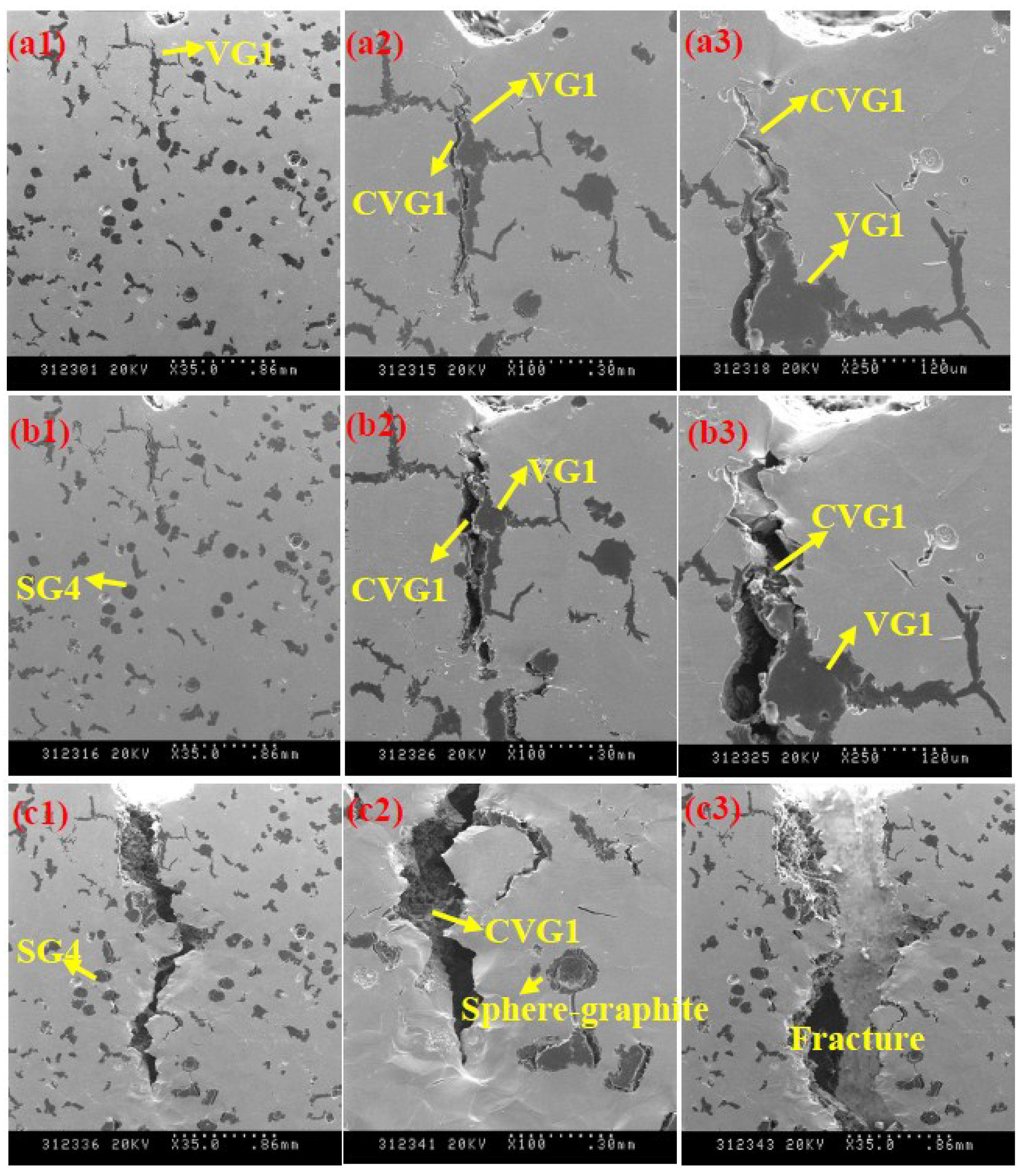
Figure 8 shows the microscopic fracture process of vermicular graphite of heavy-section ductile cast iron. Several typical locations were selected to observe the fracture process of graphite. In
Figure 8a1, VG1 is vermicular graphite. When the stretch of specimen is 2.1 mm, micro-crack CVG1 occurs within VG1 (
Figure 8a2). The micro-crack initiates at the graphite-matrix(G-M) interface and extends along the G-M interface. The micro-crack CVG1 tears the ferrite matrix at the sharp corners of vermicular graphite. Some local plastic deformation and a small amount of slip bands can be observed in front of the micro-cracks (
Figure 8a3). It can be inferred that the stress concentration is significant at the location of sharp cracks in CVG1.
Figure 8.
The crack process of vermicular graphite of heavy section ductile iron. (a1), (a2) and (a3): the stretch of specimen is 2.1 mm; (b1), (b2) and (b3): the stretch of specimen is 2.25 mm; (c1), (c2) and (c3): the stretch of specimen is 2.45 mm.
As shown in
Figure 8b1, SG4 is spheroidal graphite. When the stretch of specimen is 2.25 mm, the spheroidal graphite SG4 shows no micro-crack initiation. The micro-crack CVG1 extends and becomes wider, as shown in
Figure 8b2. The micro-crack CVG1 tears the ferrite matrix and extends to the pre-crack notch. Obvious plastic deformation can be observed in front of the micro-crack in the ferrite matrix, as shown in
Figure 8b3.
When the stretch of specimen is 2.45 mm, the micro-crack CVG1 further widens and extends, as shown in
Figure 8c1. CVG1 tears the ferrite matrix and connects with the pre-crack notch. A main crack in the matrix is formed. At the tip of the main crack, severe plastic deformation can be observed in the matrix, as shown in
Figure 8 (c2). The spherical graphite around the main crack is stripped from the ferrite matrix and plastic deformation is generated, which causes a further concentration of stress on the main crack tip. The main crack propagates unstably and eventually causes fracture, as shown in
Figure 8c3.
From the discussion above, it is clear that the vermicular graphite most likely initiates cracks along the G-M interface under the external force. The micro-cracks cause the ferrite matrix to be easily torn and extend unstably because the stress cannot be released by the plastic deformation of the matrix. The vermicular graphite can significantly reduce the conventional mechanical properties and fracture toughness of heavy section ductile iron.
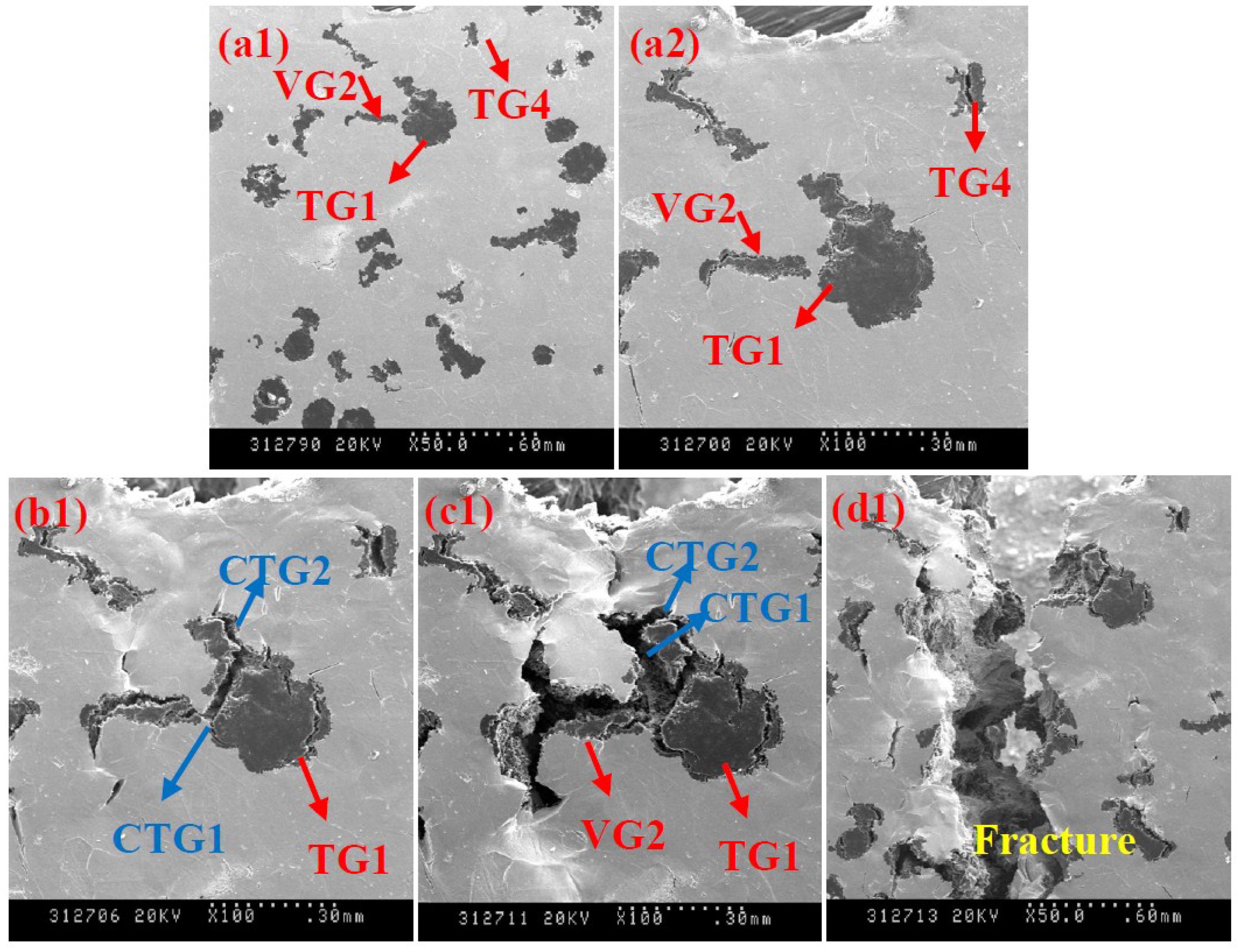
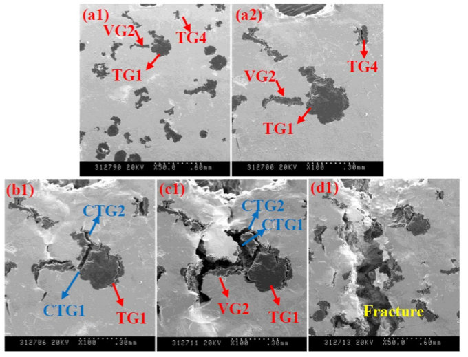
3.5. The Microscopic Fracture Process of Temper Graphite of Heavy Section Ductile Iron
Figure 9 shows the microscopic fracture process of temper graphite of heavy section ductile iron. Several typical locations were selected to observe the fracture process of graphite. As shown in
Figure 9a1, TG1, TG4 and VG2 is temper graphite, temper graphite and vermicular graphite, respectively. When the stretch of specimen is 2.1 mm, the micro-cracks can be observed in TG1, TG4 and VG2, as shown in
Figure 9a2. When the stretch of specimen is 2.25 mm, two micro-cracks CTG1 and CTG2 initiate at the tangential direction of the spheroidal section of temper graphite TG1, as shown in
Figure 9b1. Obvious plastic deformation and slip bands can be observed in front of micro-cracks in the ferrite matrix. It can be inferred that stress concentration occurs at the corners of TG1 and the ferrite matrix is torn. When the stretch of specimen is 2.45 mm, the micro-cracks in TG1 further extend, as shown in
Figure 9c1. The micro-crack CTG1 in temper graphite TG1 tears the ferrite matrix and connects with the micro-crack in vermicular graphite VG2. The micro-crack CTG2 extends along with G-M interface of dendritic branching part of TG1, and eventually tears the ferrite matrix. When the stretch of specimen is 2.79 mm, the micro-cracks in TG1 and VG2 further extend and connect with each other, forming a major crack and causing final fracture, as shown in
Figure 9d1.
From the discussion above, it is clear that the temper graphite most likely initiates cracks throughout the graphite or along the G-M interface under the external force. High local stress concentration occurs due to the presence of sharp corners of temper graphite. The matrix at the sharp corners is torn up and the micro-cracks extend unstably. The temper graphite can significantly reduce the conventional mechanical properties and fracture toughness of heavy section ductile iron.


