Abstract
In the design and integrity assessment of long-distance natural gas pipelines, it is critical to assess how geometrical features and material properties influence the stress and strain states of girth welds. This study conducted an extensive three-dimensional finite element analysis for X80 pipeline girth welds with varying geometric features and material properties to examine stress triaxiality and strain distribution phenomena. The effect of the wall thickness ratio, misalignment, strength matching coefficient, and yield-to-tensile ratio of the weld metal was analyzed under both unloaded and internal pressure-loaded conditions. The results demonstrate that stress triaxiality and local strain increase with the wall thickness ratio, amplified by increasing misalignment, yield-to-tensile ratio, and internal pressure. Enhancing weld metal strength correspondingly improves root stress and strain states; nevertheless, greater wall thickness ratios and misalignment diminish this improvement. Based on these findings, design recommendations were proposed, including suitable wall thickness ratio design, strict misalignment control and the optimization of weld material properties. The findings of this study offer valuable insights into the design and assessment of pipeline girth welds exhibiting intricate geometric features.
1. Introduction
X80 pipeline steel, noted for its exceptional combination of high strength, superior toughness, excellent weldability, and outstanding corrosion resistance, has attached significant research interest for application in long-distance natural gas transmission pipelines [1,2,3,4]. Comprehensive research has shown that girth welds are considered the structurally weak points in pipeline systems, where crack initiation and propagation are commonly observed [5,6,7]. Girth weld failures in natural gas pipelines may precipitate severe accidents, leading to casualties, economic losses, and environmental harm [8]. In 2010, the San Bruno natural gas pipeline explosion caused by girth weld failure resulted in approximately $2.5 billion in total economic impact [9]. Girth weld failures are affected by various factors, such as welding quality, material properties, geometric features, loading conditions, and geological environment [10], making the investigation of girth weld failure mechanisms a continuing priority in the pipeline field.
Over the past years, researchers have extensively employed experimental and numerical approaches to investigate the effects of weld material properties on the mechanical performance of girth welds. The strength matching relationship between weld metal and base metal significantly affects the deformation behavior and failure susceptibility of the girth welds [11,12,13]. He et al. examined the correlation between weld strength matching and strain distribution, finding that low-strength matching causes strain concentration within the weld metal, while high-strength matching results in the base metal bearing more strain, providing a protective effect [14]. Through the finite element analysis of cracked girth welds, Yan et al. found that increasing weld strength can effectively diminish crack driving force (CDF) [15]. Pisarski et al. also reported that the girth welds with high-strength machining significantly reduce the fracture toughness requirements for weld metal [16]. Verstraete found that high-strength matched girth welds exhibit lower deformation constraint, resulting in higher fracture toughness when compared to low-strength matched girth welds [17]. The yield-to-tensile ratio of materials also influences the mechanical performance of girth welds. Research conducted by Hochhauser and Meester indicated that adjusting the yield-to-tensile ratio of weld metal can improve strain distribution in girth welds [18,19]. Hertelé et al. demonstrated through a theoretical framework and finite element analysis that lower yield-to-tensile ratios are beneficial for improving the tensile strain capacity of the girth welds [20].
However, the previously mentioned studies primarily focused on girth welds with regular geometric configurations. Current failure analyses indicate that girth weld failures are frequently associated with geometric discontinuities [21,22]. Geometric discontinuities arise from specific engineering contexts, such as misalignment and unequal wall thickness. Although international pipeline standards strictly limit girth weld misalignment [23] and alignment clamps and other fixtures were employed during the construction process, systematic investigations have consistently identified numerous welds in practical engineering exhibiting misalignment significantly exceeding the limit [13]. Additionally, wall thickness transition represents an intrinsic design requirement for pipelines. When pipelines must accommodate varying operational conditions—including high-pressure segments, geological hazard areas, and densely populated area crossings—modifications to the pipeline’s mechanical properties become necessary, inevitably leading to the formation of girth welds between pipes of dissimilar wall thicknesses [24].
Geometric discontinuity has become a primary cause of girth weld fracture failures. Multiple regulatory investigations, including those conducted by the U.S. Pipeline and Hazardous Materials Safety Administration (PHMSA) [25] and the Canada Energy Regulator [26]. Inspection findings from Pipe China Corporation indicated that 56% of the 1335 defective girth welds were associated with unequal wall thickness [27].
Several researchers have investigated these geometric discontinuity issues. Sun et al. [28] examined misalignment effects and demonstrated that geometric discontinuity drives strain concentration at the root weld, correlating severity to misalignment magnitude and strength matching. Zhang [29] investigated the influence of wall thickness ratio on strain distribution. However, these studies examined each geometric feature independently, neglecting to account for synergistic effects when varying features exist—a condition frequently observed in practical engineering.
The interaction between geometric features and material properties remains unsystematically investigated. Existing research either focuses on material property effects under idealized geometry or examines geometric effects under specific material conditions, lacking a comprehensive understanding of their coupled influence. To address these critical gaps, our research team has systematically investigated girth welds with geometric discontinuities, establishing constraint-based assessment frameworks that simultaneously consider the combined effects of unequal wall thickness and misalignment features [30,31,32]. However, the influence of heterogeneous weld material properties—particularly strength matching coefficient and yield-to-tensile ratio—on stress and strain states under combined geometric discontinuities remains a critical knowledge gap. This mechanistic understanding is essential for developing reliable integrity assessment procedures for imperfect welds.
This study aims to investigate the stress and strain states of X80 pipeline girth weld joints with unequal wall thickness and misalignment features through comprehensive three-dimensional finite element analysis. Parametric studies examine the effects of geometric features (wall thickness ratio and misalignment) and material properties (strength matching coefficient and yield-to-tensile ratio) on stress triaxiality and strain distribution at the weld root. The analysis covers unloaded and internal pressure loaded conditions to clarify stress–strain response characteristics under different loading scenarios. The interaction mechanisms among various parameters are analyzed to reveal how these factors influence the sensitivity of stress and strain states. Based on the results of the analysis, targeted engineering design recommendations are proposed for the safe design and assessment of pipeline girth welds with complex geometric features.
2. Materials
2.1. X80 Girth Welding
This study included two types of materials: base metal and weld metal. The impact of weld metal properties on the stress and strain states of girth welds with unequal wall thickness and misalignment was investigated by adopting different strength matching coefficients and the yield-to-tensile ratio of the weld metal. To achieve different strength-matching conditions in girth welds, three girth weld joints were constructed using X80 pipeline steel and three different strength grades of flux-cored wires manufactured by ESAB (Montgomery, MA, USA)—E101T1, E91T1, and E71T1. After initial screening, these welding materials were chosen to provide specific weld strength gradients. The elemental compositions of the X80 steel base metal and the weld metals from the three welding wires are listed in Table 1. The base metal composition was obtained from the author team’s previous study [33], where the X80 steel was from the same supplier as used in this study. The weld metal compositions were retrieved from the ESAB official website.

Table 1.
Chemical composition of base metal and welding wires (wt.%).
Consistent procedures were employed for all girth welds during welding. STT (Surface Tension Transfer) was utilized for the root welding, followed by automated filling and capping welding with CO2 shielding gas.
2.2. Mechanical Properties of the X80 Girth Welds
Mechanical properties of the base metal and weld metals were determined by uniaxial tensile testing and test procedure followed the test standard GB/T 228.1-2021 [34]. Round bar specimens were employed for the test as shown in Figure 1, with a gauge length of 30 mm and a diameter of 6 mm. The tests were conducted on an MTS E45.105 testing machine (maximum load capacity of 100 kN) at a crosshead speed of 0.9 mm/min. The test results are presented in Figure 2.

Figure 1.
Specimen size for uniaxial tensile test.
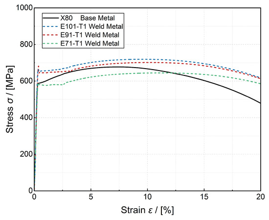
Figure 2.
The results of uniaxial tensile tests for X80 base metal and weld metal.
Figure 2 illustrates that the weld metals constructed using different welding materials exhibited significant differences in strength. The weld metal made from E101T1 exhibited the highest strength, followed by E91T1, while the weld metal from E71T1 exhibited the lowest strength. The weld metals from E101T1 and E91T1 demonstrated higher strength compared to the base metal, indicating over-matched welds, whereas the E71T1 weld metal exhibited lower strength relative to the base metal, indicating an under-matched weld. Each material was subjected to three replicate uniaxial tensile tests, with the mean values of yield strength and tensile strength recorded in Table 2.

Table 2.
Tensile properties of X80 base material and weld metal.
The disparities in mechanical properties noted among the weld metals resulted from variations in the chemical composition and microstructure of the welding metals. This table indicates that the E101T1 weld metal had the highest concentrations of Mn and Ni, with mass fractions of 1.54% and 0.97%, respectively. The E91T1 weld metal included 1.25% Mn and 0.93% Ni, and the E71T1 weld metal had 1.25% Mn and 0.22% Ni. Mn and Ni are substitutional solid solution elements for both austenite and ferrite. The atomic radius of these elements markedly differs from that of iron atoms, resulting in lattice distortion that hinders dislocation movement, thereby offering considerable solid solution strengthening [35,36]. Consequently, increased concentrations of Mn and Ni lead to enhanced weld metal strength. This is consistent with the findings of Avazkonandeh et al., who observed that increasing the content of Ni and Mn content in X80 pipeline steel welds resulted in significant improvements in both weld metal strength and acicular ferrite proportion [37].
2.3. Metallographic Characteristics of the X80 Girth Welds
To further explain the strength variations among the weld metals from the microstructural perspective, the metallographic characteristics of the three weld metals were examined using a Zeiss Axio Vert (Carl Zeiss, Jena, Germany). A1 optical microscope (made in Germany). The specimen surfaces were sanded using sandpapers with grits from 120 to 2000, and polished with 1 μm diamond polishing compound. 5% nital etchant was used to etch the specimen surfaces for 10 s. The results of metallographic characteristics are shown in Figure 3.
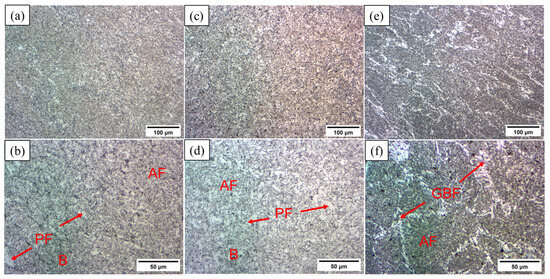
Figure 3.
X80 weld metal metallographic characteristics: (a) E101T1 200×; (b) E101T1 500×; (c) E91T1 200×; (d) E91T1 500×; (e) E71T1 200×; (f) E71T1 500×.
Figure 3a,b illustrates that the E101T1 weld has the smallest grain size, with its microstructure mainly composed of acicular ferrite (AF), bainite (B), and proeutectoid ferrite (PF). The microstructure of the E91T1 weld shows similarities to that of E101T1, although it has slightly larger grain sizes, especially for PF, as illustrated in Figure 3c,d. The E71T1 weld shows the coarsest microstructure. Along with AF and B, coarse proeutectoid ferrite can be seen nucleating at the boundaries of prior austenite grains, resulting in the formation of grain boundary ferrite (GBF), as shown in Figure 3e,f. This phenomenon occurs because in the E101T1 and E91T1 welds with higher Mn and Ni contents, Mn lowers the Ar3 temperature and slows down the pearlite transformation, encouraging heterogeneous nucleation of AF at inclusions [38,39]. At the same time, Ni is a significant stabilizer for austenite, broadening the transformation temperature range for B [40]. The combined effect of these two elements inhibits GBF formation and encourages intragranular AF refinement, which is beneficial for achieving smaller grain sizes and improving strength. The E71T1 girth weld, which has lower Mn and Ni contents, experiences a higher transformation temperature that encourages the rapid growth of PF at the boundaries of prior austenite grains. This process leads to the development of coarse, blocky, or lath-shaped GBF structures, ultimately diminishing the strength of the weld metal.
3. Finite Element Analysis Models
3.1. Geometric Parameters
Finite element analysis was employed to characterize the stress state of theX80 girth welds and the material properties determined in Section 2 were used for the constitutive model of the materials in finite element analysis. Considering the irregularity of actual girth weld cross-sections mentioned in the introduction, this study employed geometric regularization approaches to enhance model reliability while focusing on unequal wall thickness and misalignment features, as illustrated in Figure 4.
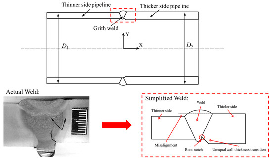
Figure 4.
Schematic diagram of the geometric regularization procedures for the girth welds (not to scale).
- (1).
- The pipe geometries on both sides of the girth weld were represented as uniform circular shapes with aligned centerlines. Misalignment was characterized by differences in the outer diameters of the pipes, excluding the impacts of axial deviations and pipe ovality variations.
- (2).
- In each girth weld joint model, all geometric features, such as uneven wall thickness, misalignment, transition angles, and weld reinforcement, exhibited total circumferential uniformity.
- (3).
- This study primarily investigated the condition in which the outer diameter of the thicker pipe exceeded that of the thinner pipe. This construction resulted in a root notch formed by the combination of root weld reinforcement and the transition slope of unequal wall thickness, which presented significant geometric discontinuity and represents the highest risk to pipeline safety.
This study included two separate girth weld geometric configurations: girth welds with only unequal wall thickness and girth welds with both unequal wall thickness and misalignment. Figure 5 shows the cross-sectional profiles and geometric parameters for each type of weld. The comprehensive modeling process is described in Section 3.3. The geometric parameters employed for the modeling process are presented in Table 3, with this combination intended to represent the typical geometric features of girth welds in engineering practice.

Figure 5.
Schematic diagram of FEM welds design: (a) the girth weld without misalignment; (b) the girth weld with misalignment.

Table 3.
Setting of finite element geometric parameters for the pipeline girth welds.
3.2. Material Properties
The impact of weld metal properties on the stress and strain states of girth welds with unequal wall thickness and misalignment was investigated by adopting different strength matching coefficients and the yield-to-tensile ratio of the weld metal. According to the standard BS7910 [41], the strength matching coefficient M is defined by the ratio of the yield strength of the weld metal σyw to the yield strength of the base metal σyb, as seen in Equation (1).
The constitutive model for the base metal was developed based on yield strength and tensile strength obtained from tests mentioned in Section 2. It adopts the stress–strain relationship proposed by Wang et al. [42], which is derived from CSA Z662 [43] through comprehensive testing and analysis. This relationship specifically addresses X60–X100 grade pipeline steels, as indicated in Equation (2).
where ε is strain, σ is stress, E is the elastic modulus (MPa), σyb is the base metal yield strength (MPa), and nb is the base metal hardening coefficient. The parameter nb can be determined using the base metal yield-to-tensile ratio λb through Equation (3):
Because this study involved the evaluation of various weld metal properties, the strength matching coefficient M and the yield-to-tensile ratio λw of the weld metal were initially determined. Following that, the yield strength and tensile strength of the weld metal were calculated, leading to the formulation of the constitutive relationship. The results of uniaxial tension tests in Section 2 indicated that the stress–strain curve of the weld metal exhibited a pronounced yield plateau. Consequently, the stress–strain equation proposed by Wu, which includes the yield plateau, was employed [21], as indicated in Equation (4).
where σyw and nw represent the yield strength and hardening coefficient of the weld metal, respectively. Wu proposed that nw can also be determined by λw, as shown in Equation (5).
As mentioned in Section 2, yielded strengths of the three weld metals were 570, 644, and 657 MPa, corresponding to strength matching coefficients of 0.97, 1.10, and 1.11. In the parametric study, these were expanded to M = 0.9, 1.0, 1.1, and 1.2 to encompass a wider range of engineering applications and account for potential strength variations from batch-to-batch material differences. The measured yield-to-tensile ratios ranged from 0.887 to 0.919. The parametric study employed λw = 0.85 and 0.95 to cover a broader engineering application range. The detailed material property parameters are listed in Table 4.

Table 4.
Setting of material property parameters for the girth welds.
3.3. Finite Element Modeling
Finite element modeling was conducted by the commercial software Abaqus 2022. Based on the parameters provided in Table 3 and Table 4, the parametric study encompassed five wall thickness ratios, two misalignments, four strength matching coefficients, and two yield-to-tensile ratios. The parameter matrix is summarized in Table 5, resulting in a total of 80 finite element models for the girth welds being created. Figure 6 illustrates a typical finite element model of a girth weld joint, along with its corresponding boundary conditions.

Table 5.
Matrix of parameters in FE analysis.
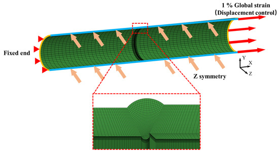
Figure 6.
Boundary conditions and meshing of the girth weld model.
Each finite element model had a total length of 8000 mm with a thin-walled pipe outer diameter D of 1219 mm. To enhance computing efficiency, a half-symmetric pipeline finite element model was established, taking into account the model’s symmetry. The model’s symmetry plane was the x-y plane, with z-direction symmetric boundary conditions applied. The left end of the pipe was fixed. An axial displacement load in the x-direction was delivered at the right end of the weld by reference point coupling. The load magnitude was set at 1% of the entire pipe length. Displacements in other directions were restricted to prevent unexpected rigid body motion in the model.
All models employed 8-node three-dimensional reduced integration solid elements (C3D8R). Mesh refinement was applied in the weld region to improve accuracy and convergence. Each model contained approximately 200,000 elements. The reliability of the finite element modeling approach employed in this study has been extensively validated in our previous work [30,44].
4. Finite Element Analysis Results and Discussion
4.1. Stress and Strain States of the Girth Welds Without Misalignment
This study identified the root notch tip (showed in Figure 4) as the hot spot location and recorded the local stress and strain for further investigation. Stress triaxiality η, defined as the ratio of hydrostatic pressure σm to von Mises equivalent stress σe, was employed to characterize the stress state, while the axial strain ε11 at the hot spot position was identified as the hot spot strain εH. Stress triaxiality accurately reflected the effect of stress state on the ductile deformation capacity and fracture behavior of weld joints, whereas axial strain immediately indicated the deformation of girth welds in the principal loading direction.
Figure 7 illustrates the stress triaxiality η at the critical site of the girth welds, which varied with different wall thickness ratios t2/t1 and strength matching coefficients M. The results indicated that η increased significantly as t2/t1 rose, especially within the interval of 1.0 ≤ t2/t1 < 1.2. Figure 7a shows that for the girth welds with a yield-to-tensile ratio of weld metal λw = 0.85, when M = 0.9, the increment in η was 0.240 as t2/t1 rose. When M = 1.2, the increment in η was 0.287 under the same conditions. The comparison indicated that η presented higher sensitivity to t2/t1 changes under greater M.
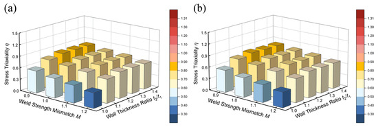
Figure 7.
The stress triaxiality η in the girth welds without misalignment: (a) λw = 0.85; (b) λw = 0.95.
The increase of M significantly reduced stress triaxiality at the weld root position. For equal wall thickness girth welds (t2/t1 = 1.0), the reduction in η was 0.180 as M rose from 0.9 to 1.2. This decreasing effect was also observed in unequal wall thickness girth welds. In the girth welds with t2/t1 = 1.4, the reduction in η due to the increase in M was only 0.136, which was smaller than the reduction noted in the equal wall thickness girth welds. The comparison of Figure 7a,b demonstrates negligible changes in the calculation results between the conditions of λw = 0.85 and λw = 0.95, suggesting that λw had minimal influence on η in the girth welds without misalignment.
Variations in η resulted from the combined influences of geometric discontinuity and material strength. The unequal wall thickness feature induced geometric discontinuity, intensifying local stress concentration and increasing stress triaxiality. The impact of weld strength enhancement presented two sides. Increasing M limited weld deformation and diminishes restrictions from surrounding materials, leading to a decreasing η. Conversely, high-strength welds exhibited minimal deformation, thereby inhibiting local stress relaxation and making η more sensitive to t2/t1 variations. Consequently, while weld strength enhancement could reduce η, this advantage diminished in joints with larger t2/t1.
Geometrical features and material properties significantly influenced the hot spot strain εH. Figure 8 illustrates the εH changed with t2/t1 and M under two λw conditions. The results demonstrate that, under determined M and λw conditions, the εH initially increased and then decreased with increasing t2/t1, peaking at t2/t1 = 1.2. Quantitative analysis indicates that M significantly affected the εH sensitivity. In Figure 8a, girth welds with λw = 0.85 showed a 1.24% increase in εH due to t2/t1 variations when M = 0.9, compared to 0.32% for M = 1.2, demonstrating that weld metal strength enhancement significantly diminishes the effect of t2/t1 on εH. The comparison of Figure 8a,b indicates that the effect of λw was also influenced by weld metal’s strength. Under low-strength matching conditions (M = 0.9), as λw rose from 0.85 to 0.95, the εH increment due to t2/t1 increased from 1.24% to 1.96%. Under conditions of high strength matching (M = 1.2), the effect of λw was negligible.
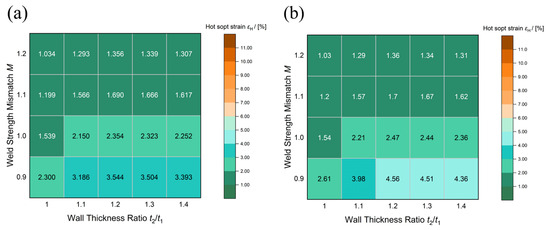
Figure 8.
The hot spot strain in the girth welds without misalignment: (a) λw = 0.85; (b) λw = 0.95.
Figure 9 illustrates the axial strain distribution contours at 1% nominal pipeline strain, which validate the analysis results above. In low-strength matching welds with M = 0.9, the weld experienced an obvious strain concentration, which was exacerbated as t2/t1 increased. Increasing λw further exacerbated this strain concentration, causing the high-strain region to extend towards the cap weld toe when λw = 0.95. When M reached 1.0 or higher, strain concentration within the weld significantly diminished, and the influence of t2/t1 and λw was substantially reduced. When M = 1.2, the influence of geometric features and material parameters on strain distribution became negligible.
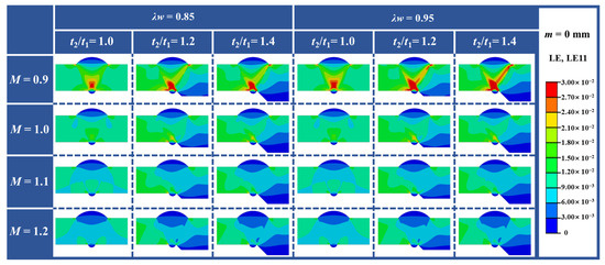
Figure 9.
The axial strain distribution in the girth welds without misalignment.
Variations of the strain state resulted from the combination of deformation coordination and material property interactions. The non-monotonic behavior of εH with t2/t1 demonstrated competing mechanisms: increasing t2/t1 exacerbated geometric discontinuity and local strain concentration, while under higher t2/t1 conditions, the thinner pipe section was subjected to more global deformation, reducing local strain concentration [44]. The parameter M significantly influenced strain distribution—higher M values diminished weld deformation and root strain concentration. The effect of λw depended on weld strength: in low-strength welds, greater plastic deformation in the weld metal made λw effects significant; in high-strength welds, lower plastic deformation diminished λw influence. Consistent with the findings of this study, He et al.’s research also mentioned the protective effect of high-strength matching on circumferential welds [14]. However, their research primarily focused on the girth welds with ideal structures. This study further suggests that geometric discontinuities in girth welds would diminish this protective effect.
Comprehensive analysis indicates that in unequal wall thickness girth welds without misalignment, stress triaxiality η is primarily influenced by t2/t1 and M, while the influence of λw is negligible. Increasing t2/t1 raises η and the risk of fracture. However, increasing M decreases η, with diminishing effectiveness at large t2/t1. For strain, εH increases with t2/t1 and λw, whereas M effectively reduces these effects and regulates strain uniformity. Using these findings, two design suggestions can be proposed. First, t2/t1 should not exceed 1.2, as this range exhibits the most significant variations in stress and strain; higher wall thickness ratios require counterbore-taper transitions [29]. Second, the selection of weld strength requires careful consideration of its dual effects—while a high M decreases η, it also increases sensitivity to geometric variations, thereby necessitating stricter dimensional control during manufacturing. Moreover, sufficient weld toughness is critical to prevent brittle fracture in the high-strength welds.
4.2. Stress and Strain States of the Girth Welds with 2 mm Misalignment
To investigate how geometric features and material properties influence the stress and strain states in unequal wall thickness girth welds with misalignment, this study introduced a 2 mm misalignment condition for further analyzing and comparing with the results from Section 4.1.
Misalignment significantly increased the stress triaxiality in the girth welds. Under the same wall thickness ratios and weld metal properties, Figure 7 and Figure 10 demonstrate that η in girth welds with 2 mm misalignment is generally 0.2–0.4 higher than those without misalignment. The substantial increase indicates that misalignment exacerbated the weld root stress condition, increasing the risk of brittle fracture. The sensitivity of η to variations in t2/t1 significantly increased when m = 2 mm. As illustrated in Figure 10a, with λw = 0.85 and M = 0.9, increasing t2/t1 from 1.0 to 1.4 led to a more pronounced η increment of 0.388, compared to 0.238 in the girth welds without misalignment. The increment in η under the same conditions was 0.415 when M = 1.2, significantly exceeding the case without misalignment. The result indicates that misalignment intensified the effects of t2/t1 variations on stress states. Sun et al. also found that misalignment leads to significant stress and strain concentration at the weld root [28], consistent with the findings of this study.
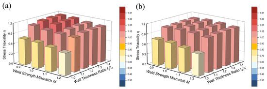
Figure 10.
The stress triaxiality η in the girth welds with 2 mm misalignment: (a) λw = 0.85; (b) λw = 0.95.
In girth welds with a 2 mm misalignment, the effect of M on η was diminished. When t2/t1 = 1.0, increasing M from 0.9 to 1.2 led to a 0.124 reduction in η, significantly less than 0.180 in girth welds without misalignment. When t2/t1 = 1.4, the reduction in η decreased to 0.097. This finding indicates that misalignment limited the improvement of weld strength enhancement on stress states. The parameter λw exhibited significant effects in girth welds with a 2 mm misalignment. When M = 0.9, increasing λw from 0.85 to 0.95 decreased the increment in η due to t2/t1 variations from 0.388 to 0.328. The η increment decreased from 0.415 to 0.406 under the same condition when M = 1.2. The results demonstrate that increasing λw diminished the sensitivity of η to t2/t1 variations, especially in lower matching conditions.
Consistent with the findings in Section 4.1, η variations in the girth welds with misalignment arose from geometric-material interactions. Misalignment deepened the root notch, exacerbating geometric discontinuity and stress concentration, which increased both η and its sensitivity to t2/t1 variations. This pronounced geometric effect also limited the benefits of weld strength enhancement. Furthermore, λw exhibited a significant influence in the welds with misalignment: higher λw values led to stress redistribution through plastic deformation when stresses exceed yield strength [45], reducing η sensitivity to t2/t1 variations.
The influence of misalignment on hot spot strain concentration was more significant and complex. Figure 11 illustrates the variation of hot spot strain εH with t2/t1 and M in the girth welds with 2 mm misalignment. Misalignment increased strain concentration at the root weld position compared to Figure 8’s results under m = 0 mm conditions. The influence of all parameters on εH was significantly enhanced in the girth welds with 2 mm misalignment. Figure 11a shows that when M = 0.9 and λw = 0.85, the increment in εH due to t2/t1 variation reached 5.89%, 4.75 times higher than in girth welds without misalignment. When M = 1.2, the increment in εH was 1.24%, 3.44 times that of the girth welds without misalignment. The amplification effect of λw was more significant with misalignment. As shown in Figure 11b, increasing λw from 0.85 to 0.95 with M = 0.9 led to εH more than doubling. In the girth welds with λw = 0.95, the increment in εH resulting from t2/t1 variations was 9.54% when M = 0.9 and 1.42% when M = 1.2, indicating that the influence of λw was more pronounced under low-strength matching conditions.
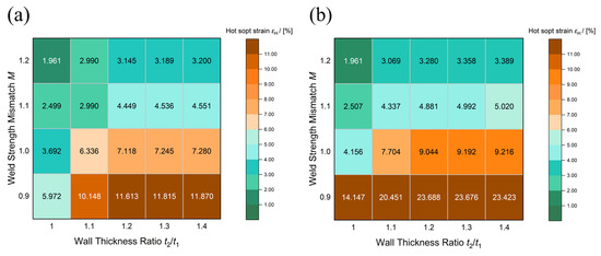
Figure 11.
The hot spot strain in the girth welds with 2 mm misalignment: (a) λw = 0.85; (b) λw = 0.95.
Strain distribution analysis clarifies the influence of misalignment on the strain field of the girth welds in Figure 12. Under low-strength matching conditions (M = 0.9), misalignment resulted in the formation of a through-thickness strain concentration band within the weld, extending from the root notch to the cap weld toe on the thin-walled side. This band’s area and strain values significantly increased with rising t2/t1 and λw. When M increased to 1.0, the area of the strain concentration band decreased significantly, and the influence of t2/t1 and λw diminished markedly. When M = 1.2, strain concentration was primarily localized to the root notch tip region, and the strain distribution within the weld was similar to that of the girth weld without misalignment. The phenomenon of strain concentration band inside the weld induced by misalignment is consistent with that was observed in the research of Zhang et al. [29] and Hu et al. [30].
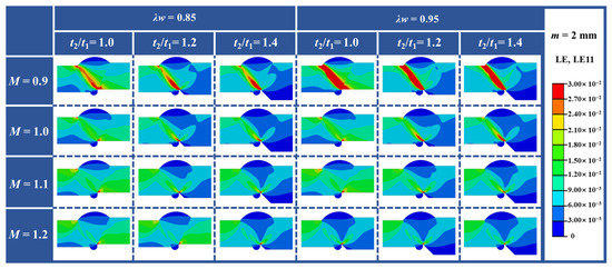
Figure 12.
The axial strain distribution in the grith welds with 2 mm misalignment.
The effect of misalignment on strain state resulted from changing load transfer mechanisms. Non-collinear loads caused by misalignment produced additional bending moments at the weld, creating combined tension-bending loading that subjected the root to greater tensile strain. This loading condition enhanced the effects of t2/t1, M, and λw on the strain state.
The analysis above demonstrates that misalignment further exacerbates stress and strain states in unequal wall thickness girth welds. In the girth welds with misalignment, η is higher and exhibits greater sensitivity to t2/t1, while the improvement of M is diminished. Moreover, misalignment exacerbates strain concentration at the weld root and significantly intensified the effects of t2/t1 and λw on εH, especially pronounced in low-strength matching welds. M remains the most effective factor for improving stress and strain states, but a sufficiently high M is necessary to reduce the effect of misalignment. Consequently, in girth weld design and welding, two additional aspects are required to be considered besides the recommendations in Section 4.1. First, misalignment must be strictly controlled to prevent excessive stress–strain concentration. Second, since misalignment cannot be avoided entirely, weld metals with lower yield-to-tensile ratios should be used to provide necessary safety margins for potential geometric defects.
4.3. Stress and Strain States of the Girth Welds with Internal Pressure
Previous analysis was primarily performed on the girth welds in unloaded conditions, while an operating pipeline girth weld has to bear internal pressure load during its service life. Consequently, to further investigate the stress and strain states in the grith welds with internal pressure, unequal wall thickness girth welds subjected to an internal pressure of P = 10 MPa were analyzed. In finite element analysis of the girth welds with P ≠ 0, the load application required two analysis steps: initially, fixed constraints were applied at both ends of the pipeline, while the internal pressure was increased to the designated value; subsequently, the internal working pressure was held constant while displacement-controlled axial tensile loads were applied.
4.3.1. The Influence of Internal Pressure on the Stress States of the Girth Welds
The stress triaxiality at P = 10 MPa of the hot spot location in unequal girth welds without misalignment was analyzed and compared with the results under P = 0 MPa from the preceding analysis, and the results are illustrated in Figure 13. In Figure 13, the upper and lower boundaries of each colored rectangle denote the η values at P = 10 MPa and P = 0 MPa, and the height of the rectangle reflects the sensitivity of η to P variations.
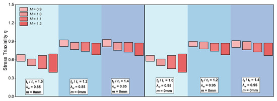
Figure 13.
Stress triaxiality variation intervals in the girth welds without misalignment.
Figure 13 illustrates that the stress triaxiality at the weld root increased with internal pressure. This phenomenon arose from additional circumferential stress caused by internal pressure, which complicated the stress field at the root weld. Figure 14 demonstrates the variation of the increments in η resulting from increasing P, considering varying t2/t1, M, and λw. This figure illustrates that η became more sensitive to P variations as M increased. For example, in girth welds with λw = 0.85 and t2/t1 = 1.0, the increments in η caused by internal pressure at M = 0.9 and 1.2 were 0.11 and 0.30, respectively. Higher weld strength made it more difficult to release the additional stress caused by internal pressure through deformation, resulting in more pronounced increments in η with increasing internal pressure.

Figure 14.
The increment of η resulted from P increasing in the girth welds without misalignment: (a) λw = 0.85; (b) λw = 0.95.
Meanwhile, in girth welds without misalignment, increasing t2/t1 diminished the sensitivity of η to P variations. For the girth welds with λw = 0.85 and M = 1.2, the increments in η for t2/t1 = 1.0 and 1.4 were 0.30 and 0.20, respectively. This sensitivity reduction resulted from the stress redistribution between the weld metal and the thinner base metal in unequal wall thickness girth welds. In such cases, the thinner side base metal endured more stress, diminishing the η sensitivity to P variations. This phenomenon has also been discussed in previous studies [44,46]. Comparison of Figure 14a,b demonstrates that λw had less effect on the sensitivity of η to P variations in the girth welds without misalignment.
Figure 15 and Figure 16 illustrate the variation of increments in η caused by increasing P in girth welds with 2 mm misalignment. Misalignment significantly increased the overall level of stress triaxiality in girth welds under internal pressure. In unequal wall thickness girth welds (t2/t1 = 1.2 and 1.4), misalignment increased the sensitivity of η to P variations. For example, in the girth welds with m = 2 mm, λw = 0.85, and M = 1.1, the increments in η resulting from P increasing for t2/t1 = 1.0 and 1.4 were 0.203 and 0.187, respectively, which were higher than the values of 0.150 and 0.158 observed in girth welds without misalignment under the same conditions. This indicated that the combination of misalignment and unequal wall thickness features exacerbated the adverse effects of internal pressure on the stress state.
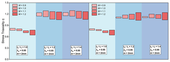
Figure 15.
Stress triaxiality variation intervals in the girth welds with 2 mm misalignment.

Figure 16.
The increment of η resulted from P increasing in the girth welds with 2 mm misalignment: (a) λw = 0.85; (b) λw = 0.95.
Additionally, in girth welds with 2 mm misalignment, the influence of λw was more pronounced. Figure 16 illustrates that increasing λw diminished the sensitivity of η to P variations, consistent with the results in Section 4.2. This occurred because when local stress exceeded the yield strength, materials with high yield-to-tensile ratio were easier to plastic deformation, enabling more stress redistribution, which diminished stress concentration and reduced stress triaxiality.
The analysis demonstrates that internal pressure significantly changes the stress state of girth welds. Increasing internal pressure further elevates η at the girth weld root. Meanwhile, the combination of unequal wall thickness and misalignment features significantly increases the sensitivity of η to P variations. This phenomenon is more pronounced in girth welds with higher strength matching, increasing design risk and uncertainty.
4.3.2. The Influence of Internal Pressure on the Strain States of the Girth Welds
Internal pressure also significantly influenced the strain state in girth welds. To investigate the influence of various factors on the sensitivity of εH to P variations, the increments in εH resulting from an increase in P from 0 MPa to 10 MPa were recorded for pipeline girth welds both with and without 2 mm misalignment. The results are illustrated in Figure 17 and Figure 18.
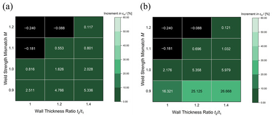
Figure 17.
The increment of εH resulted from P increasing in the girth welds without misalignment: (a) λw = 0.85; (b) λw = 0.95.
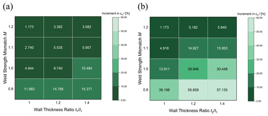
Figure 18.
The increment of εH resulted from P increasing in the girth welds with 2 mm misalignment: (a) λw = 0.85; (b) λw = 0.95.
As Figure 17 illustrates that in the girth welds without misalignment, the sensitivity of εH to P variations increased with increasing t2/t1 and decreased with M increasing, and M had a more significant influence. For the girth welds with low strength matching (M = 0.9), εH significantly increased with P increasing. In the girth welds with λw = 0.85, the increments in εH were 2.51% and 5.34% when t2/t1 = 1.0 and 1.4, respectively. As M increased, the sensitivity of εH decreased sharply, and εH even decreased with P increasing in the girth welds with M ≥ 1.1. This decline occurred because the base metal bore the deformation induced by internal pressure in the high-strength matching girth welds. The comparison of Figure 17a,b demonstrates that λw significantly affected εH in the girth welds with internal pressure. The εH increments in girth welds with M = 0.9 and t2/t1 = 1.4 increased from 5.33% to 26.7% as λw increased from 0.85 to 0.95.
Figure 18 illustrates that the geometric discontinuity resulting from misalignment enhanced the influence of P on εH. Furthermore, the influence of t2/t1 was more pronounced in girth welds with misalignment. For girth welds with m = 2 mm, M = 0.9, and λw = 0.85, the increments in εH resulting from P variations, when t2/t1 = 1.0 and 1.4, were 11.98% and 15.38%, respectively. The values were significantly higher than 2.51% and 5.34% observed in girth welds without misalignment. In the girth welds with 2 mm misalignment, increasing M significantly decreased the sensitivity of εH to P variations. In girth welds with M = 1.2 and λw = 0.85, the εH increments were merely 1.17% and 3.58% when t2/t1 = 1.0 and 1.4, respectively. The comparison of Figure 18a,b demonstrates that misalignment further exacerbated the influence of λw on strain. In girth welds with m = 2 mm, M = 0.9, and t2/t1 = 1.4, the increments in εH increased from 15.38% to 57.13% as λw increased from 0.85 to 0.95.
Compared to unloaded conditions, internal pressure significantly increases stress triaxiality and strain concentration levels at the girth weld root. The influences of t2/t1, λw, and m on stress and strain states are more pronounced in girth welds subjected to internal pressure. Meanwhile, the effect of increasing M on stress and strain states is more significant in girth welds subjected to internal pressure. These results indicate that when designing unequal wall thickness girth welds subjected to loading conditions, it is essential to take into account the harmonious alignment of geometric features and material properties. Additionally, stricter control standards for geometric defects are essential to ensure structural safety and reliability under complex loading conditions.
5. Conclusions
This study examined the stress and strain states of X80 pipeline girth welds considering different geometric features and weld metal properties through a combined approach of experimental characterization and three-dimensional finite element parametric analysis. The experimental work included uniaxial tensile testing and microstructural characterization of three girth welds made from different weld materials. It determined strength matching coefficients and yield-to-tensile ratio ranges, and clarified the influence mechanisms of alloying elements on microstructure and mechanical properties. Based on these experimental data, numerical finite element analyses were conducted incorporating the wall thickness ratio t2/t1, misalignment m, strength matching coefficient M, and yield-to-tensile ratio λw. The effects of these factors on stress triaxiality and strain distribution at the girth weld root hot spot location were explained under both unloaded and internal pressure-loaded conditions. The integration of experimentally validated parameters with finite element analysis enhances the reliability of this study. Specific engineering design recommendations were derived from the results of the analysis. The conclusions from this study are summarized as follows:
- (1)
- Experimental characterization reveals that weld metal strength variations (M = 0.97–1.11) primarily result from differences in Mn and Ni content in the welding materials. These two elements provide significant solid solution strengthening effects and adjust phase transformation temperatures to promote the formation of fine acicular ferrite, improving the microstructure and enhancing the strength of the weld metals.
- (2)
- Finite element analysis indicates that unequal wall thickness critically influences the stress and strain states at the weld root location. Stress triaxiality η and hot spot strain εH increase as the wall thickness ratio increases. In the girth welds with λw = 0.85, M = 0.9, and no misalignment, as t2/t1 increased from 1.0 to 1.4, the increments in η and εH were 0.238 and 1.24%, respectively.
- (3)
- Numerical analysis reveals that misalignment significantly exacerbates the stress and strain states of girth welds. With 2 mm misalignment, η increased by 0.2–0.4, while the increment in εH from t2/t1 variations reached 5.89%, far exceeding the welds without misalignment. The combination of unequal wall thickness and misalignment exacerbates geometric discontinuity, causing severe stress–strain concentration at the weld root.
- (4)
- Weld metal properties significantly affect girth weld stress–strain states. Calculation results indicate that increasing M reduces stress–strain concentration, but its effectiveness diminishes with geometric discontinuity. For m = 0 and t2/t1 = 1.0, raising M from 0.9 to 1.2 reduced η by 0.180; however, for m = 2 mm and t2/t1 = 1.4, the reduction was only 0.097. Higher λw reduces η and increases εH, particularly in undermatched welds with misalignment.
- (5)
- Numerical simulation demonstrates that internal pressure significantly increases stress triaxiality η and hot spot strain εH at the weld root. The effects of t2/t1, m and λw on stress and strain states are more pronounced under internal pressure-loaded conditions. Higher M intensifies the stress triaxiality response to internal pressure while effectively reducing strain concentration sensitivity.
- (6)
- Based on the analysis results, the design of unequal wall thickness girth welds should limit the wall thickness ratio to ≤1.2 with strict misalignment control, employ counterbore-taper design for larger wall thickness ratios, maintain a high strength matching coefficient with adequate toughness, and select weld metals with low yield-to-tensile ratios to mitigate stress and strain concentration.
Author Contributions
Conceptualization, C.D. and B.G. (Baoming Gong); Methodology, Y.L.; Software, B.G. (Baichen Guo) and Y.L.; Validation, B.G. (Baichen Guo) and J.N.; Formal analysis, B.G. (Baichen Guo); Investigation, C.D., B.G. (Baoming Gong) and K.Z.; Resources, C.D.; Data curation, B.G. (Baichen Guo); Writing—original draft, B.G. (Baichen Guo); Writing—review & editing, J.N. and K.Z.; Visualization, B.G. (Baichen Guo); Supervision, C.D.; Project administration, B.G. (Baoming Gong); Funding acquisition, C.D. All authors have read and agreed to the published version of the manuscript.
Funding
This research was funded by Pipe China Research on the Failure Mechanism for Girth Weld of High Steel Pipeline (WZXGL202105).
Data Availability Statement
The raw data supporting the conclusions of this article will be made available by the authors on request.
Conflicts of Interest
The authors declare no conflicts of interest.
References
- Tan, Z.; Yang, L.; Zhang, D.; Wang, Z.; Cheng, F.; Zhang, M.; Jin, Y. Development mechanism of internal local corrosion of X80 pipeline steel. J. Mater. Sci. Technol. 2020, 49, 186–201. [Google Scholar] [CrossRef]
- Xia, F.; Li, Z.; Ma, M.; Zhao, Y.; Wu, C.; Su, X.; Peng, H. Effect of Nb on microstructure and corrosion resistance of X80 pipeline steel. Int. J. Press. Vessel. Pip. 2023, 203, 104949. [Google Scholar] [CrossRef]
- Xu, K.; Qiao, G.-y.; Shi, X.-b.; Xiao, F.-r. Effect of stress-relief annealing on the fatigue properties of X80 welded pipes. Mater. Sci. Eng. A 2021, 807, 140854. [Google Scholar] [CrossRef]
- Sharma, S.K.; Maheshwari, S. A review on welding of high strength oil and gas pipeline steels. J. Nat. Gas Sci. Eng. 2017, 38, 203–217. [Google Scholar] [CrossRef]
- Chang, Q.; Cao, Y.; Zhen, Y.; Wu, G.; Li, F. Study on the effect of loading conditions on the fracture behavior of pipeline with girth weld. Int. J. Press. Vessel. Pip. 2023, 203, 104940. [Google Scholar] [CrossRef]
- Cao, Y.; Chang, Q.; Zhen, Y. Numerical simulation of fracture behavior for the pipeline with girth weld under axial load. Eng. Fail. Anal. 2022, 136, 106221. [Google Scholar] [CrossRef]
- Wang, X.; Shuai, J.; Zhang, S.-Z.; Ren, W.; Zhu, X.-M. Numerical study on the strain capacity of girth-welded X80 grade pipes. Pet. Sci. 2022, 19, 2399–2412. [Google Scholar] [CrossRef]
- Sweeney, M.; Gasca, A.H.; Garcia-Lopez, M.; Palmer, A.C. Pipelines and Landslides in Rugged Terrain: A Database, Historic Risks and Pipeline Vulnerability. In Proceedings of the Terrain and Geohazard Challenges Facing Onshore Oil and Gas Pipelines, London, UK, 2–4 June 2004; pp. 641–659. [Google Scholar]
- National Transportation Safety Board. Pipeline Accident Report: Pacific Gas and Electric Company Natural Gas Transmission Pipeline Rupture and Fire; National Transportation Safety Board: San Bruno, CA, USA, 2011.
- Wang, K.; Zhang, M.; Guo, Q.; Ma, W.; Zhang, Y.; Wu, W. Failure Risk Prediction Model for Girth Welds in High-Strength Steel Pipeline Based on Historical Data and Artificial Neural Network. Processes 2023, 11, 2273. [Google Scholar] [CrossRef]
- Jiang, J.; Zhang, H.; Zhang, D.; Ji, B.; Wu, K.; Chen, P.; Sha, S.; Liu, X. Fracture response of mitred X70 pipeline with crack defect in butt weld: Experimental and numerical investigation. Thin-Walled Struct. 2022, 177, 109420. [Google Scholar] [CrossRef]
- Yang, Y.; Zhang, H.; Wu, K.; Chen, P.; Sui, Y.; Yang, D.; Liu, X. Strain capacity analysis of the mismatched welding joint with misalignments of D 1,422 mm X80 steel pipelines: An experimental and numerical investigation. J. Pipeline Sci. Eng. 2021, 1, 212–224. [Google Scholar] [CrossRef]
- Feng, Q.-S.; Zhang, Y.-H. Review and discussion of strength mismatch of girth welds in high strength pipelines. Int. J. Press. Vessel. Pip. 2024, 208, 105118. [Google Scholar] [CrossRef]
- He, W.; Liu, X.; Wang, Q.; Mu, L.; Qin, Z.; Lei, X. Fault Recovery Strategy for Active Distribution Network Considering Repair Sequence Under Extreme Weather. In Proceedings of the 2022 Asian Conference on Frontiers of Power and Energy (ACFPE), Chengdu, China, 21–23 October 2022; pp. 63–69. [Google Scholar]
- Yan, B.-C.; Wang, L.; Wu, G.-Y.; Zhang, Y.-H. Evaluation of strain based ECA method in DNVGL-RP-F108. Int. J. Press. Vessel. Pip. 2023, 202, 104909. [Google Scholar] [CrossRef]
- Pisarski, H.G.; Tkach, Y.; Quintana, M. Evaluation of Weld Metal Strength Mismatch in X100 Pipeline Girth Welds. In Proceedings of the 2004 International Pipeline Conference, Calgary, AL, Canada, 4–8 October 2004; pp. 1589–1596. [Google Scholar]
- Verstraete, M.A.; De Waele, W.; Denys, R.M.; Van Minnebruggen, K.; Hertelé, S. Constraint analysis of defects in strength mismatched girth welds of (pressurized) pipe and Curved Wide Plate tensile test specimens. Eng. Fract. Mech. 2014, 131, 128–141. [Google Scholar] [CrossRef]
- Hochhauser, F.; Ernst, W.; Rauch, R.; Vallant, R.; Enzinger, N. Influence of the Soft Zone on The Strength of Welded Modern Hsla Steels. Weld. World 2012, 56, 77–85. [Google Scholar] [CrossRef]
- Meester, B.d. The Weldability of Modern Structural TMCP Steels. ISIJ Int. 1997, 37, 537–551. [Google Scholar] [CrossRef]
- Hertelé, S.; O’Dowd, N.; Van Minnebruggen, K.; Denys, R.; De Waele, W. Effects of pipe steel heterogeneity on the tensile strain capacity of a flawed pipeline girth weld. Eng. Fract. Mech. 2014, 115, 172–189. [Google Scholar] [CrossRef]
- Wu, K.; Liu, X.; Zhang, H.; Sui, Y.; Zhang, Z.; Yang, D.; Liu, Y. Fracture response of 1422-mm diameter pipe with double-V groove weld joints and circumferential crack in fusion line. Eng. Fail. Anal. 2020, 115, 104641. [Google Scholar] [CrossRef]
- Wang, L.; Tang, Y.; Ma, T.; Zhong, J.; Li, Z.; Zhang, Y.; Xuan, H. Stress concentration analysis of butt welds with variable wall thickness of spanning pipelines caused by additional loads. Int. J. Press. Vessel. Pip. 2020, 182, 104075. [Google Scholar] [CrossRef]
- ASME B31.8 2022; Gas Transmission and Distribution Piping Systems. The American Society of Mechanical Engineers: New York, NY, USA, 2022.
- Sui, Y.; Wang, P. Girth weld welding technology for Heihe-Changling section of The Eastern Natural gas pipeline between China and Russia. Oil Gas Storage Transp. 2020, 39, 961–970. [Google Scholar]
- Pipeline and Hazardous Materials Safety Administration. Pipeline Safety: Girth Weld Quality Issues Due to Improper Transitioning, Misalignment, and Welding Practices of Large Diameter Line Pipe; PHMSA: Washington, DC, USA, 2010.
- Canada Energy Regulator. Girth Weld Area Strain-Induced Failures: Pipeline Design, Construction, and Operation Considerations; CER: Singapore, 2020. [Google Scholar]
- You, X.G.L. Inspection and Disposal of Girth Weld Defects of Oil and Gas Pipelines. Pet. Tubul. Goods. Instrum. 2020, 6, 42–45. [Google Scholar] [CrossRef]
- Sun, P.; Jia, H.; Chen, J.; Li, X.; Han, B. Study on root strain concentration of girth weld joint with variable wall thickness for X80 pipe. Int. J. Press. Vessel. Pip. 2023, 202, 104887. [Google Scholar] [CrossRef]
- Zhang, D.; Liu, X.; Yang, Y.; Chen, P.; Zhang, H.; Hou, X.; Zhang, H. Fracture behavior analysis of X80 pipelines welded joints with unequal wall thickness. J. Constr. Steel Res. 2023, 208, 108000. [Google Scholar] [CrossRef]
- Hu, W.; Gong, B.; Chang, Q.; Zhao, Z.; Dai, L.; Liu, Y. Strain fracture behaviors and crack equivalence of X80 welded joints with non-sharp notches at weld root. Int. J. Press. Vessel. Pip. 2025, 214, 105414. [Google Scholar] [CrossRef]
- Guo, B.; Deng, C.; Wang, Y.; Gong, B.; Ning, J.; Dai, L.; Shen, K.; Zhou, S. Fracture analysis of X80 welded joints with variable wall thickness and misalignment. J. Constr. Steel Res. 2024, 219, 108778. [Google Scholar] [CrossRef]
- Ning, J.; Deng, C.; Dai, L.; Liu, Q.; Gong, B.; Guo, B.; Wang, Y. Fracture behavior analysis of X80 girth welds considering misaligned and variable-wall-thickness geometric features via modified single-edge notched tensile (MSENT) specimens. Eng. Fract. Mech. 2025, 317, 110910. [Google Scholar] [CrossRef]
- Li, Q.; Wang, D.; Deng, C.; Wu, S.; Gao, Z.; Zhao, H.; Liang, H. Role of microstructure heterogeneity on hydrogen-assisted fracture toughness degradation of X80 weld metal in H2S-saturated solution. Corros. Sci. 2023, 224, 111467. [Google Scholar] [CrossRef]
- GB/T 228.1-2021; Metallic Materials—Tensile Testing—Part 1: Method of Test at Room Temperature. Technical Committee 183 on Steel of Standardization Administration of China: Beijing, China, 2021.
- Han, S.Y.; Shin, S.Y.; Seo, C.-H.; Lee, H.; Bae, J.-H.; Kim, K.; Lee, S.; Kim, N.J. Effects of Mo, Cr, and V additions on tensile and Charpy impact properties of API X80 pipeline steels. Metall. Mater. Trans. A 2009, 40, 1851–1862. [Google Scholar] [CrossRef]
- Mohrbacher, H.; Kern, A. Nickel alloying in carbon steel: Fundamentals and applications. Alloys 2023, 2, 1–28. [Google Scholar] [CrossRef]
- Sheykh Jaberi, F.; Kokabi, A.H. Influence of Nickel and Manganese on Microstructure and Mechanical Properties of Shielded Metal Arc-Welded API-X80 Steel. J. Mater. Eng. Perform. 2012, 21, 1447–1454. [Google Scholar] [CrossRef]
- Babu, S.S. The mechanism of acicular ferrite in weld deposits. Curr. Opin. Solid State Mater. Sci. 2004, 8, 267–278. [Google Scholar] [CrossRef]
- Hejazi, D.; Haq, A.J.; Yazdipour, N.; Dunne, D.P.; Calka, A.; Barbaro, F.; Pereloma, E.V. Effect of manganese content and microstructure on the susceptibility of X70 pipeline steel to hydrogen cracking. Mater. Sci. Eng. A 2012, 551, 40–49. [Google Scholar] [CrossRef]
- Bilmes, P.D.; Solari, M.; Llorente, C.L. Characteristics and effects of austenite resulting from tempering of 13Cr–NiMo martensitic steel weld metals. Mater. Charact. 2001, 46, 285–296. [Google Scholar] [CrossRef]
- BS 7910:2019; Guide to Methods for Assessing the Acceptability of Flaws in Metallic Structures. British Standards Institution: Singapore, 2019.
- Wang, Y.-Y.; Liu, M.; Song, Y.; Stephens, M.; Petersen, R.; Gordon, R. Second Generation Models for Strain-Based Design; Pipeline Research Council International: Houston, TX, USA, 2011. [Google Scholar]
- CSA Z662-2007; Oil and Gas Pipeline Systems. Canadian Standards Association: Singapore, 2007.
- Ning, J.; Deng, C.; Wang, Y.; Gong, B.; Guo, B.; Wang, C.; Zhao, N.; Dai, L. Stress state analysis of root notch for X80 girth welds with variable wall thickness and misalignment geometric features. Int. J. Press. Vessel. Pip. 2023, 206, 105064. [Google Scholar] [CrossRef]
- Anderson, T.L. Fracture Mechanics Fundamentals and Applications Fourth Edition; CRC Press: Boca Raton, FL, USA, 2017. [Google Scholar]
- Guo, B.; Zhu, Y.; Dai, L.; Deng, C.; Peng, H.; Wang, D.; Liang, H. Stress state at the root of variable-wall-thickness pipeline welded joint. Int. J. Press. Vessel. Pip. 2022, 200, 104785. [Google Scholar] [CrossRef]
Disclaimer/Publisher’s Note: The statements, opinions and data contained in all publications are solely those of the individual author(s) and contributor(s) and not of MDPI and/or the editor(s). MDPI and/or the editor(s) disclaim responsibility for any injury to people or property resulting from any ideas, methods, instructions or products referred to in the content. |
© 2025 by the authors. Licensee MDPI, Basel, Switzerland. This article is an open access article distributed under the terms and conditions of the Creative Commons Attribution (CC BY) license (https://creativecommons.org/licenses/by/4.0/).