Article

Effect of Induction Hardening Following Carburizing–Nitriding Duplex Treatment on the Microstructure and Fatigue Strength of JIS-SCM420 Low-Alloy Steel

1
Graduate School of Engineering Science, Yokohama National University, 79-5 Tokiwadai, Hodogaya, Yokohama 240-8501, Japan
2
Faculty of Engineering, Yokohama National University, 79-5 Tokiwadai, Hodogaya, Yokohama 240-8501, Japan
*
Author to whom correspondence should be addressed.
Metals 2025, 15(9), 944; https://doi.org/10.3390/met15090944
Submission received: 30 July 2025 / Revised: 23 August 2025 / Accepted: 24 August 2025 / Published: 25 August 2025
(This article belongs to the Special Issue Advances in the Fatigue and Fracture Behaviour of Metallic Materials)

Abstract

In this study, a duplex treatment combining carburizing, nitriding, and subsequent induction hardening (IH) was applied to JIS-SCM420 low-alloy steel. A comprehensive evaluation was conducted to assess surface characteristics, including microstructure, hardness, residual stress, and fatigue performance. The IH process successfully produced a high-nitrogen-content ε-Fe2-3(N,C) compound layer (2–3 μm thick) and fine acicular martensite at the surface, significantly enhancing surface hardness (950 HV0.03) and inducing beneficial compressive residual stress (−477 MPa). The IH-treated material exhibited a plane-bending fatigue strength of approximately 775 MPa, notably higher than that of conventionally carbonitrided specimens (700 MPa). This improvement was primarily attributed to the formation of the hard ε-Fe2-3(N,C) compound layer and refined martensitic structure resulting from induction hardening. Additionally, IH activated residual interstitial elements, promoting the precipitation of stable surface nitrides. These microstructural changes effectively suppressed fatigue crack initiation and propagation, thereby extending fatigue life under cyclic loading conditions.

1. Introduction

To improve fuel efficiency and reduce CO2 emissions, the automotive industry is continually pursuing advanced materials and processes that enhance component performance without compromising structural integrity or increasing costs. Among these efforts, surface hardening treatments play a critical role in increasing the wear resistance, fatigue strength, and overall durability of key components such as gears, shafts, and bearings [1,2,3,4].
Conventionally, carburizing [5,6,7] and nitriding [8,9,10] treatments have been widely employed. More recently, carbonitriding has emerged as an alternative method aimed at reducing CO2 emissions [10,11,12]. Carbonitriding is a thermochemical surface treatment conducted in the austenitic region to improve the surface properties of low-alloy steels. In our previous study [13], we examined the characteristics of carbonitrided surfaces, including microstructure, hardness, and residual stress. We also evaluated the effects of sub-zero treatment on the volume fraction of retained austenite (γR) and carbide formation. Additionally, the impact of these surface characteristics on fatigue strength was clarified.
However, due to the competitive diffusion behavior of carbon and nitrogen, the nitrogen content near the surface is lower than expected [12,13,14,15]. This nitrogen deficiency hinders nitride formation, which is essential for achieving high surface hardness and compressive residual stress—both of which are critical for enhancing fatigue performance [16].
To address this issue, a duplex treatment combining carburizing and nitriding was applied to increase nitrogen content and promote the formation of a nitride layer on the surface. However, this treatment did not result in the formation of a martensitic layer or a distinct nitride layer at the surface. Moreover, no significant improvement in surface hardness was observed. To overcome these limitations, induction hardening (IH) was applied following the duplex treatment. IH is a well-established, energy-efficient, and environmentally friendly technology. It involves heating electrically conductive materials through electromagnetic induction without direct contact [17,18,19,20,21]. When alternating current flows through an induction coil, eddy currents are generated within the material, producing localized heat due to electrical resistance [17,20]. This enables rapid and precise heating of targeted areas, resulting in improved surface hardness, compressive residual stress, and fatigue strength [17,19,20,22,23].
In this study, JIS-SCM420 steel was subjected to carburizing and nitriding, followed by induction hardening, to produce a hardened surface layer with elevated nitrogen content and a hardened diffusion zone. Surface properties such as microstructure, hardness, and residual stress were analyzed, and their effects on fatigue performance were evaluated. To address the issue of nitrogen deficiency noted in our previous work on carbonitriding [13], the present study employed a different approach by separating the carburizing and nitriding steps, followed by a final induction hardening (IH) treatment. This was designed to maximize surface nitrogen content and explore a novel surface modification route for enhancing fatigue properties.

2. Experimental Procedure

2.1. Materials and Heat Treatment

The material used in this study was JIS-SCM420 low-alloy steel (compositionally equivalent to ASTM 4118; C 0.22, Si 0.26, Mn 0.86, S 0.02, Cu 0.01, Ni 0.02, Cr 1.21, Mo 0.20 mass%), which is commonly used in machine structural components. A continuously cast bloom was hot-rolled into a billet measuring 180 mm × 180 mm and then hot-forged into a round bar with a diameter of 35 mm. The forged bar was normalized at 1198 K for 7.2 ks to homogenize the microstructure.
Figure 1 shows the schematic diagram of the duplex surface treatment, which consisted of carburizing followed by nitriding. The geometry of the Schenck-type plane-bending fatigue specimen is detailed in our previous work [13] and is not reproduced here. Carburizing was performed using acetylene (C2H2) gas in a low-pressure vacuum atmosphere. Due to the high reactivity of C2H2, a pulse-controlled pressure modulation technique was used to stabilize surface reactions and promote uniform carbon diffusion. During this process, the internal pressure was cyclically varied between 60 Pa and 1–3 kPa, with C2H2 injected at 10 L/pulse every 180 s. A two-stage nitriding process (‘boost-diffuse’) was employed to enhance near-surface nitrogen activity while limiting excessive compound-layer growth.
Following carburizing, nitriding was carried out at atmospheric pressure using N2 gas at a flow rate of 1 m3/h. Two nitriding conditions were employed: one at 873 K with a nitriding potential of KN = 0.4 and another at 773 K with KN = 0.2.
Subsequently, induction hardening was carried out in an ambient air atmosphere by rapidly heating the treated surface to 1063 K for 1.1 s using high-frequency electromagnetic induction. The specimens were then immediately quenched in water and tempered at 453 K to relieve residual stresses and stabilize the martensitic microstructure. Specimens subjected to induction hardening are hereafter referred to as IH, while those without induction hardening are denoted as Non-IH.
Plane-bending fatigue test specimens were machined from the longitudinal axis of the forged bar using a Schenck-type configuration. All specimens were mechanically polished to eliminate surface irregularities.

2.2. Fatigue Testing

Load-controlled plane-bending fatigue tests were conducted at room temperature using a fatigue testing machine. A stress ratio of R = σmin / σmax = −1 was applied, indicating fully reversed loading, where the specimen surface cycles between maximum tensile and maximum compressive stress of equal magnitude. The loading frequency was 20 Hz. Each test was terminated upon specimen failure or after 107 cycles, whichever occurred first. The mean stress was 0 MPa (R = −1), and the stress amplitude (σa) for each condition is reported with the S–N data.

2.3. Microstructure and Surface Characterization

Prior to all analyses, specimens were mechanically ground with SiC paper up to #2000 grit. A final polishing step was then performed with a 0.05 μm colloidal silica suspension to maintain a consistent surface finish. Particularly for the fatigue test specimens, this final step was performed meticulously to rigorously eliminate any superficial defects that could influence the test results. The surface of the gauge section was buff-polished while monitoring the specimen thickness in 1 µm increments. Polishing was continued until the thickness no longer changed, ensuring the removal of any pre-existing micro-cracks or altered layers.
Microstructural analysis was conducted using optical microscopy (OM; ME60, Nikon Corp., Tokyo, Japan), field-emission scanning electron microscopy (FE-SEM; JSM-7001F, JEOL Ltd., Tokyo, Japan), and electron backscatter diffraction (EBSD; OIM™, EDAX Inc., Mahwah, USA). The morphology and distribution of retained austenite (γR) were examined by EBSD. Depth profiles of carbon and nitrogen were measured using field-emission electron probe microanalysis (FE-EPMA; JEOL JXA-8530F). Elemental quantification was performed using standard ZAF correction procedures [24].
Phase identification of the surface layers was carried out using X-ray diffraction (XRD; SmartLab, Rigaku Corp., Tokyo, Japan) with Cu-Kα radiation (λ = 1.541 Å) over a 2θ scan range of 35–70° and a step size of 0.01°. The analysis was conducted in Bragg–Brentano (θ–2θ) geometry.
Cross-sectional microhardness profiles were obtained using a Micro-Vickers hardness tester (HM-200, Mitutoyo Corp., Kanagawa, Japan) with a test load of 30 gf and a dwell time of 15 s.
Residual stress and γR content at the specimen surface, both before and after fatigue testing, were evaluated using a portable X-ray diffractometer (μ-360s, PULSTEC industrial Co. Ltd., Shizuoka, Japan). Surface residual stress was measured by the cos α method using Cr-Kα radiation on the {211} diffraction plane of α-Fe. The retained austenite fraction (γR) was obtained from the integrated intensities of γ and α peaks.

3. Results and Discussion

3.1. Concentration–Depth Profiles of Carbon and Nitrogen

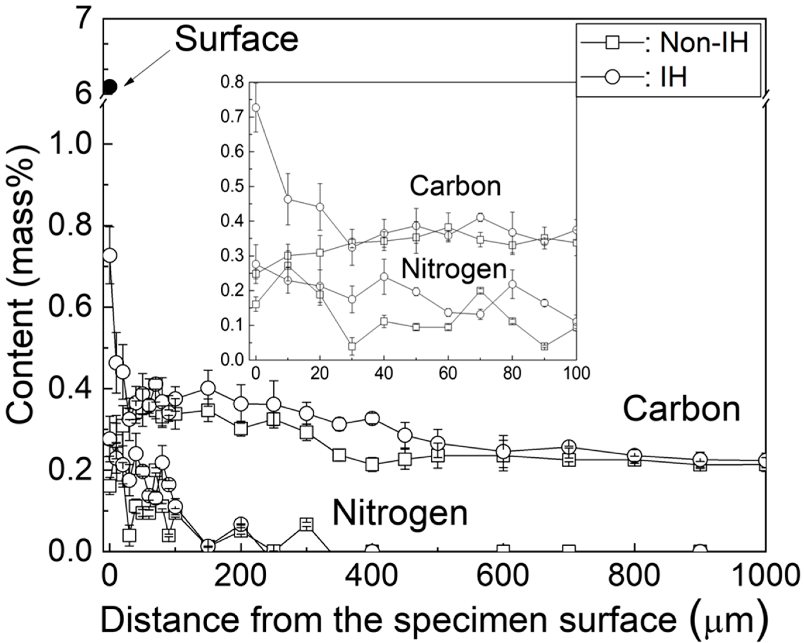
Figure 2 shows the carbon and nitrogen concentration–depth profiles of the Non-IH and IH specimens. In the Non-IH specimen, the nitrogen concentration generally decreased from the surface inward, although some local fluctuations were observed within the first 100 µm, which may be attributed to the localized formation of fine nitrides in addition to measurement uncertainty. This inverse relationship is attributed to competitive diffusion and chemical interactions between carbon and nitrogen atoms. Near the surface, nitrogen preferentially occupies interstitial sites or forms stable compounds such as nitrides and carbonitrides, leading to decarburization or hindering carbon diffusion. These effects arise from differences in the diffusion kinetics and chemical reactivity of the two elements [12,14,25,26]. It should be noted that the comparison to Ref. [12], which utilized a high-carbon steel, is intended to be conceptual to illustrate the principle of competitive diffusion, as a direct quantitative comparison is limited by the differing material compositions.
In contrast, the IH specimen exhibited a distinct nitrogen peak at the surface, reaching approximately 6.1 wt.% while maintaining a surface carbon concentration of 0.72 wt.%. However, beneath the surface, nitrogen content declined sharply and stabilized at approximately 0.28 wt.%, similar to that of the Non-IH specimen. This behavior suggests that the localized thermal input and rapid cooling associated with the IH process enhanced nitrogen absorption at the surface but did not promote deep nitrogen diffusion. Consequently, the nitrided layer remained shallow (less than 5 μm), limiting its influence on bulk hardening behavior.

3.2. Microstructure

Figure 3 presents optical micrographs of the microstructures. The Non-IH specimen (Figure 3a) exhibited a tempered microstructure, while the IH specimen (Figure 3b) displayed a distinct surface-hardened layer, which consisted of a thin, white compound layer on the outermost surface and fine martensite beneath it. The specific morphologies of this martensite are further detailed in the subsequent SEM analysis. This structure results from elevated carbon and nitrogen concentrations. Typically, higher carbon levels promote the formation of acicular martensite, whereas lower concentrations favor lath martensite formation [27]. A significant difference in the retained austenite (γR) fraction was also observed between the two conditions. The Non-IH specimen exhibited a high γR content of 26.2%, whereas the subsequent IH treatment reduced this fraction to 13.3%.
Figure 4 presents cross-sectional SEM images of the IH specimen. The surface-hardened layer extended to a depth of approximately 170 μm, with a distinct microstructural change observed at this boundary (Figure 4a). The high-magnification image of the surface region (Figure 4b) revealed a nitride layer approximately 2–3 μm thick, along with fine acicular martensite formed due to high local enrichment of carbon and nitrogen. Additionally, carbides were uniformly precipitated along prior austenite grain boundaries, attributed to carbon supersaturation and rapid cooling. During the IH process, the microstructure exists in the austenite phase, which has high carbon solubility. Subsequent rapid cooling limits carbon diffusion, resulting in localized carbon enrichment within grains or at grain boundaries, thereby promoting carbide precipitation [28,29]. A microstructural transition occurred at a depth of about 170 μm from the surface. Beyond this point, the microstructure consisted of coarser lath martensite (Figure 4c). The evolution of these microstructures and the trend in martensite grain size align with the carbon and nitrogen concentration profiles shown in Figure 2. The core region, less influenced by the heat treatment, primarily contained lath martensite. These microstructural variations reflect changes in the martensite start (Ms) temperature caused by diffusion gradients of carbon and nitrogen, as well as the rapid cooling associated with the IH process [21,30].
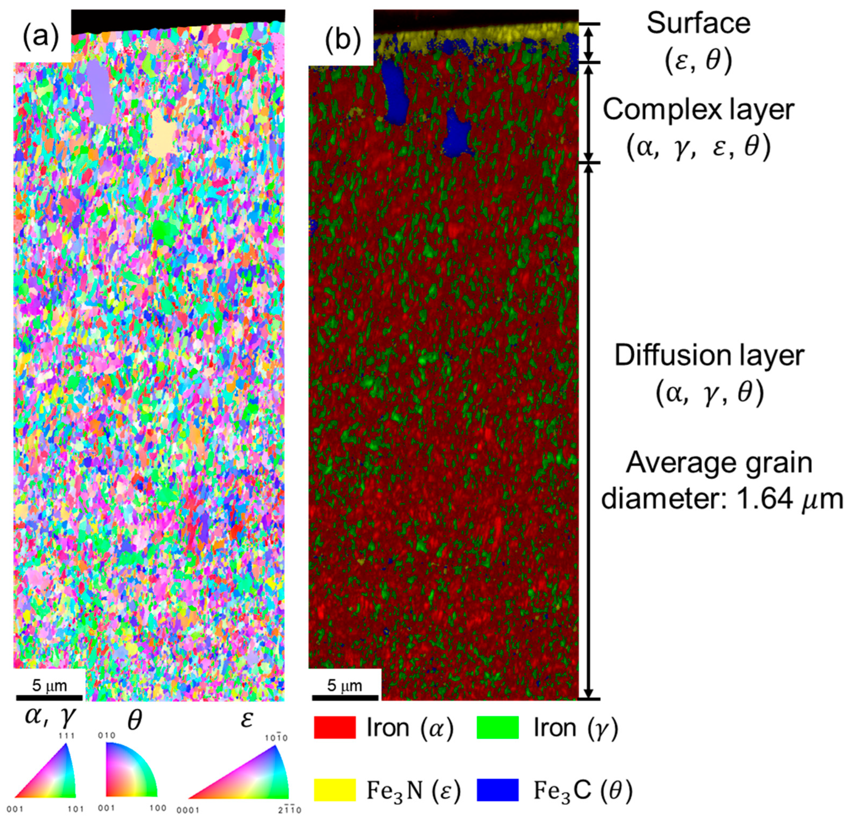
Figure 5 presents the EBSD analysis results of the IH specimen. The inverse pole figure (IPF) map (Figure 5a) revealed a highly refined martensitic structure with an average grain diameter of approximately 1.64 μm. The corresponding phase map (Figure 5b) confirmed that the outermost surface consisted of ε-Fe2-3(N,C) with a hexagonal close-packed (HCP) structure. The underlying diffusion layer comprised acicular martensite interspersed with γR and cementite, indicating a composite microstructure formed due to thermal cycling and elemental gradients introduced by induction hardening.
As shown in Figure 6, X-ray diffraction (XRD) analysis using Cu–Kα radiation was performed to identify the surface crystal structures of the base metal (BM) and the IH specimen. The diffraction pattern of the BM specimen displayed prominent peaks corresponding to the α-Fe phase, including α(110), α(200), and α(211), along with a weak γ(111) peak, indicative of a tempered martensitic structure containing retained austenite.
In contrast, the IH specimen exhibited a significantly altered diffraction profile. The α-Fe peaks were greatly reduced, while sharp peaks corresponding to ε-Fe2-3(N,C) (HCP), Fe16N2 (BCC), and Fe3C became dominant, along with weak peaks that could be tentatively assigned to Mo2N. The appearance of the ε-Fe2-3(N,C) peak near 2θ ≈ 43.5° confirmed the formation of a hard nitride layer at the surface. The presence of Fe3C indicates localized cementite precipitation, attributed to rapid cooling and carbon supersaturation of austenite prior to martensitic transformation. Given that JIS-SCM420 steel contains Cr and Mo, the formation of fine, stable alloy nitrides or carbonitrides in addition to iron nitrides is also thermodynamically favorable, which can further contribute to high surface hardness.
These findings align with the microstructural observations from SEM and EBSD (Figure 4 and Figure 5), confirming that induction hardening transformed the surface region into a nitride–martensite composite. This transformation results from the rapid thermal cycling of induction heating, which causes redistribution and surface enrichment of dissolved nitrogen. This nitrogen enrichment promotes the formation of a thin ε-Fe2-3(N,C) compound layer at the outermost surface. Beneath this layer lies a refined martensitic diffusion zone supersaturated with both carbon and nitrogen, partially replacing the original tempered α–Fe matrix. While the presence of fine carbides contributes to the overall hardness, a reliable quantitative estimation of their volume fraction was beyond the scope of this study, as it would require techniques such as transmission electron microscopy (TEM). Therefore, the discussion of precipitates in this work remains qualitative.

3.3. Hardness

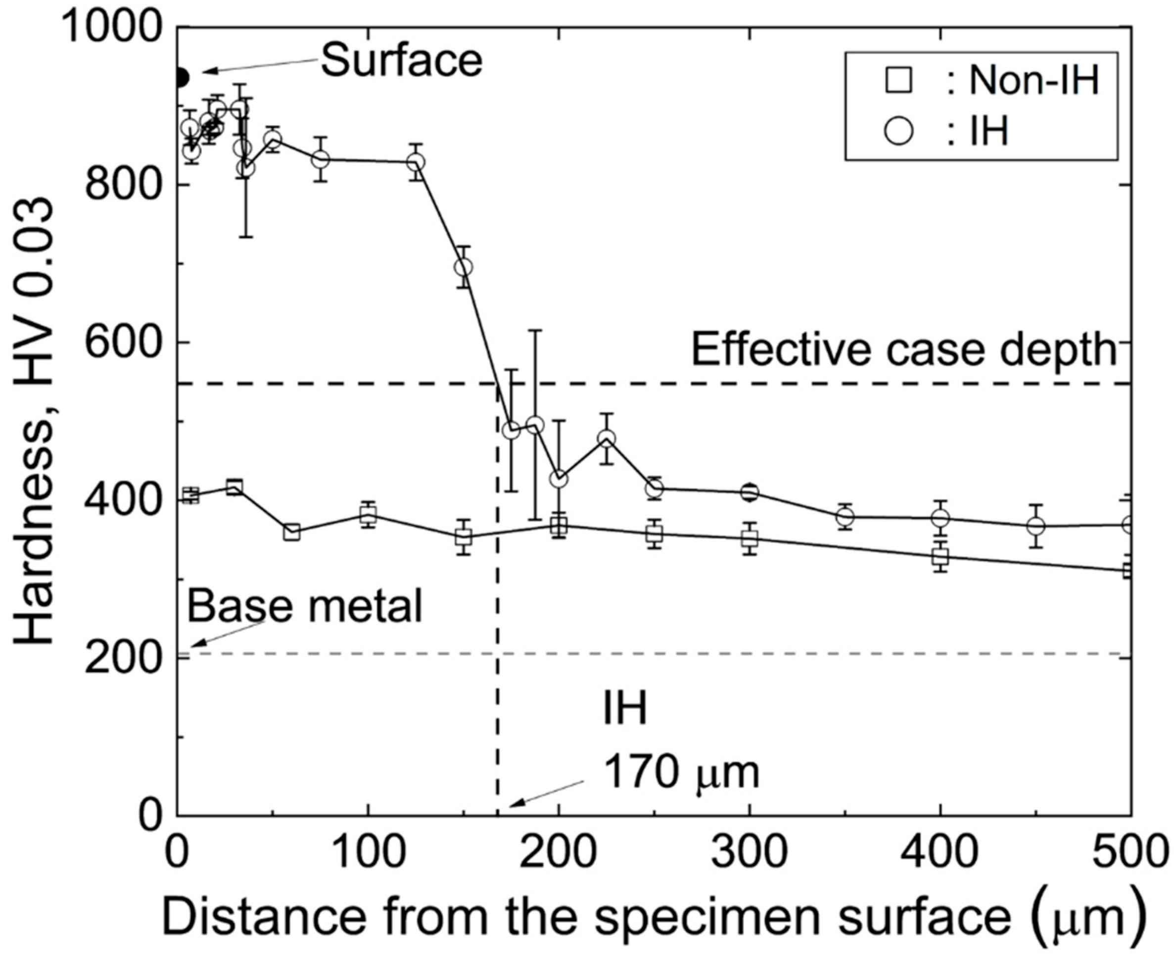
Figure 7 presents the cross-sectional Vickers hardness profiles of the Non-IH and IH specimens. The Non-IH specimen exhibited a surface hardness of approximately 400 HV0.03, reflecting a modest increase of about 200 HV0.03 compared to the base material (BM). However, this indicates that the carburizing and nitriding treatments alone did not develop a distinct hardened layer. As shown in Figure 2, nitrogen diffusion reduced the surface carbon concentration, and nitrogen—along with carbon, which is also a strong austenite stabilizer—lowered the martensite start (Ms) temperature. Together, these effects inhibited full martensitic transformation, resulting in only a limited increase in surface hardness [31].
In contrast, the IH specimen exhibited a substantial increase in surface hardness, reaching approximately 950 HV0.03. This enhanced hardness is primarily attributed to the formation of a thin ε-Fe2-3(N,C) compound layer along with fine acicular martensite. The diffusion layer beneath the nitride layer showed a gradual decrease in hardness, from about 900 HV0.03 near the surface to approximately 720 HV0.03 at greater depths, reflecting the compositional gradients in carbon and nitrogen concentrations. This layer also contained γR and cementite, whose localized distributions contributed to hardness fluctuations [32,33,34]. The effective case depth (ECD), defined as the depth from the surface where the Vickers hardness drops to 550 HV0.03 [35], was approximately 170 μm, consistent with the depth of the transformed microstructure observed in SEM and EBSD. This achieved case depth of 170 µm at the 550 HV threshold, combined with a peak surface hardness of 950 HV0.03, represents a desirable property combination for demanding applications like gears, which require both high surface wear resistance and sufficient case depth to support high contact stresses.
The formation of this ~170 µm case depth is governed by a dual mechanism. First, the thermal profile is established by the induction heating process; the skin depth of the eddy currents determines how deep the steel is rapidly heated into the austenite phase. Second, within this thermally affected zone, the final microstructure upon quenching is controlled by the local chemical composition, where the high C and N content ensures the formation of a hard martensitic structure.

3.4. Progression of Retained Austenite (γR) and Residual Stress During Fatigue Testing

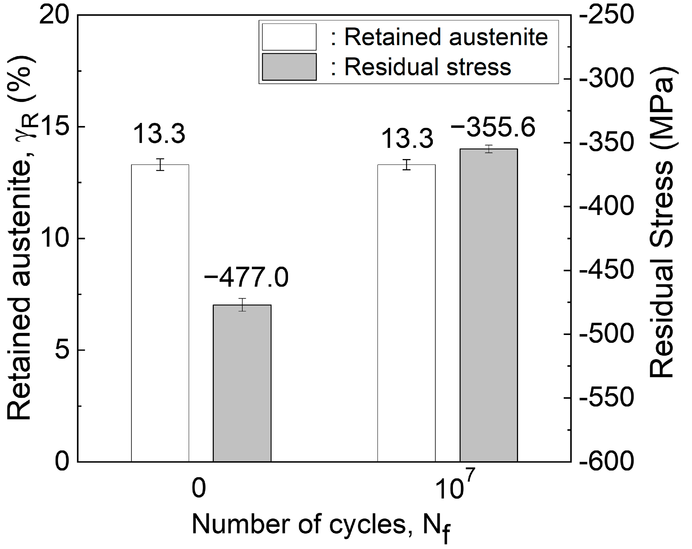
Figure 8 presents the XRD results for the surface fraction of γR and residual stress in the IH specimen, both before and after fatigue testing. Initially, the surface γR content was 13.3%, and the compressive residual stress was −477.0 MPa. The IH treatment induced high compressive residual stress due to rapid heating and cooling rates [17,18,19,20,21].
The nitrogen content in the IH specimen acted as an austenite-stabilizing element, maintaining a relatively high γR fraction (13.3%). Notably, the γR content remained unchanged after fatigue testing, indicating that no stress- or strain-induced transformation from γR to martensite occurred during the test. Nitrogen stabilized the face-centered cubic (FCC) austenite phase both chemically and mechanically; thus, the stress amplitude corresponding to the fatigue limit (775 MPa) was insufficient to trigger martensitic transformation [13,36,37].
After fatigue testing, the compressive residual stress decreased to −355.6 MPa, representing a reduction of approximately 121.4 MPa. This decrease can be attributed to the interplay of two competing mechanisms [38,39,40,41]. The first is stress relaxation, in which localized plastic deformation reduces compressive residual stress once the accumulated internal stress exceeds the yield strength. The second is stress intensification due to volumetric expansion associated with the transformation of austenite (FCC) to martensite (BCT), which can increase compressive residual stress. However, since no γR transformation was observed, only the stress relaxation mechanism was active in the IH specimen, resulting in the observed reduction in residual stress.

3.5. S–N Data

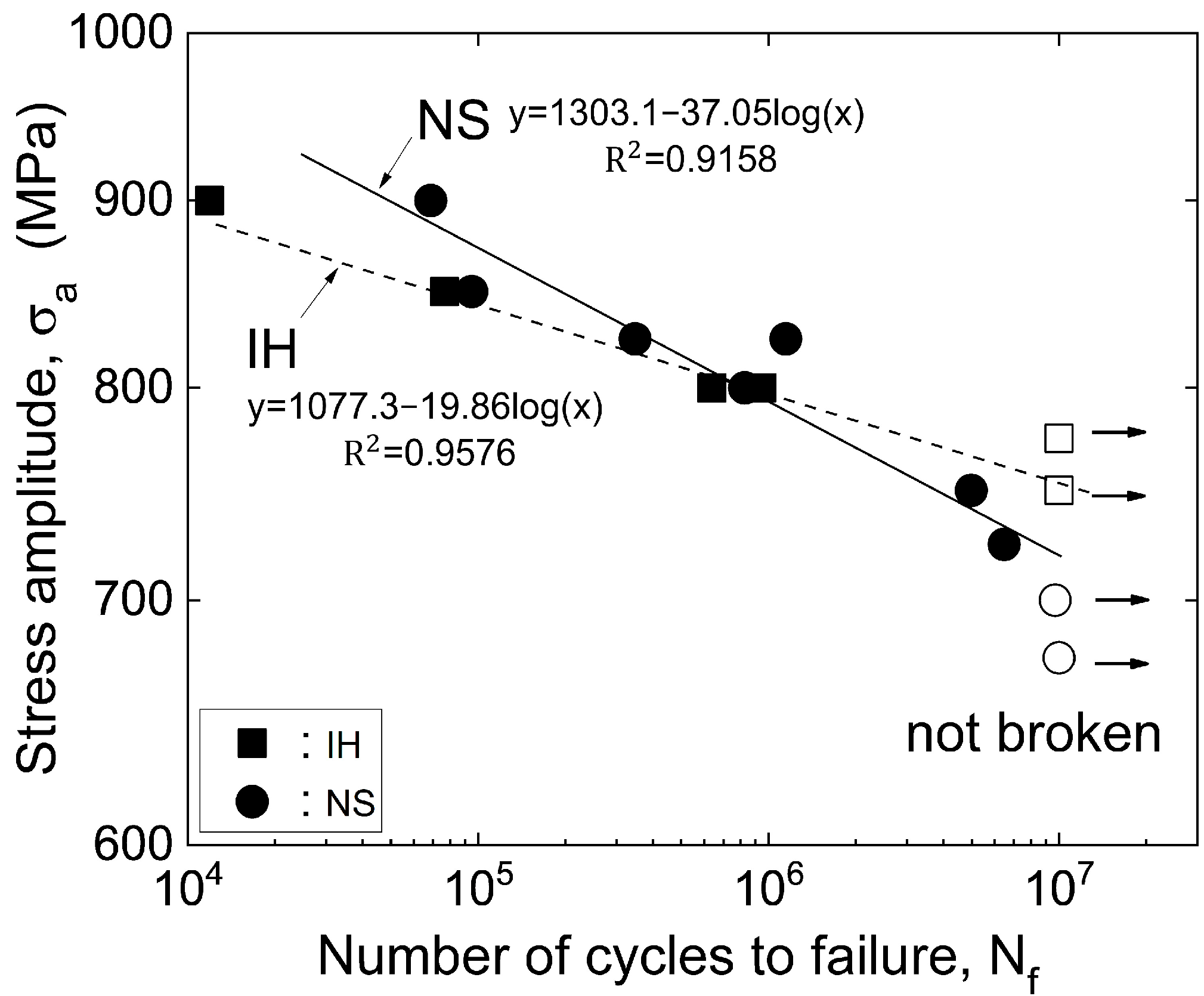
Figure 9 presents the S–N curves obtained from plane-bending fatigue tests for the IH specimen. To assess the improvement in fatigue strength achieved through induction hardening, the fatigue data for the IH specimens were compared with those of the carbonitrided specimen (NS) specimens reported in a previous study [13]. Open squares and circles indicate specimens that did not fail even after 107 cycles.
The analysis showed that the fatigue strength of the IH specimen was approximately 775 MPa, surpassing that of the NS specimen (700 MPa). Both specimens exhibited a monotonic increase in the number of cycles to failure with decreasing applied stress amplitude, displaying a strong linear relationship on a semi-logarithmic scale. The coefficients of determination (R2) for the linear fits were 0.958 and 0.916 for the IH and NS specimens, respectively.
The fatigue strength at a specific number of cycles σ n a was calculated using the logarithmic approximation equation [7,42]:
σ n a = A B l o g N f
where A is the strength coefficient, which is related to the material’s resistance to crack initiation and is thus strongly influenced by surface hardness and compressive residual stress; B is the life exponent, which reflects the material’s sensitivity to crack propagation and is governed by the underlying microstructure and the stability of the residual stress field; and Nf is the number of cycles to failure. The extracted fitting parameters were A = 1077.3 and B = 19.86 for the IH specimen and A = 1303.1 and B = 37.05 for the NS specimen. These results indicate that the IH specimen exhibited slightly lower fatigue strength under short-term, high-stress conditions but outperformed the NS specimen under prolonged cyclic loading. This trend is attributed to the formation of a nitrogen-rich ε-Fe2-3(N,C) surface layer and high-hardness martensite induced by induction hardening. These microstructural changes effectively suppress crack initiation and enhance resistance to fatigue crack propagation, thereby extending the overall fatigue life.

3.6. Bending Fatigue Fractured Surfaces

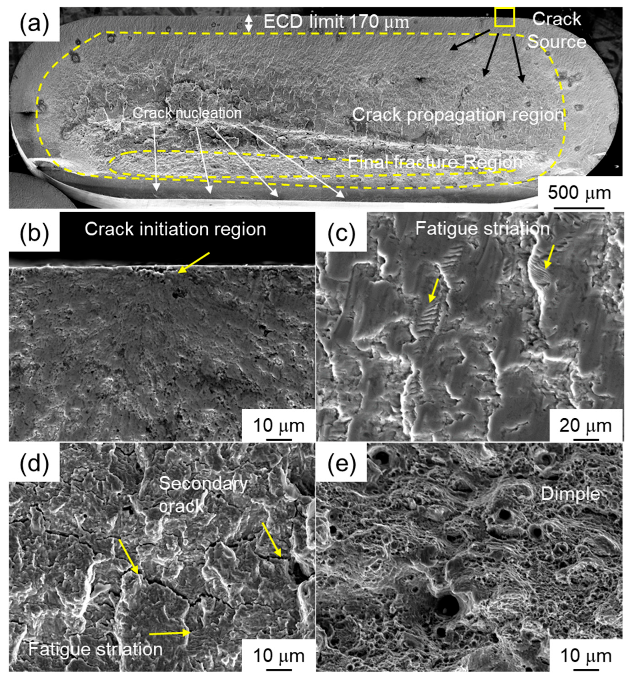
Figure 10 presents SEM fractographs of the IH specimen after plane-bending fatigue testing. As shown in Figure 10a, fatigue cracks initiated at the specimen surface, with multiple nucleation sites observed. These cracks propagated radially along the high-hardness diffusion layer. As shown in Figure 10b, the fatigue crack originating at the surface propagated through interfacial cracking of the nitride and diffusion layers.
Fatigue cracks propagated along prior austenite grain boundaries, accompanied by the formation of fatigue striations (Figure 10c). As confirmed in Figure 5, the diffusion layer comprised a heterogeneous microstructure of martensite, γR, and cementite. The differences in fracture resistance among these phases resulted in non-uniform crack growth behavior. Consequently, the spacing between fatigue striations in this region varied within the range of approximately 0.498–1.089 μm [43].
During the intermediate stage of crack growth, the increased toughness of the matrix led to well-defined striations and the formation of secondary cracks (Figure 10d). These secondary cracks helped alleviate local stress concentrations and blunt the main crack tip, thereby enhancing resistance to crack propagation [44].
As crack growth progressed toward the specimen interior, the effective load-bearing cross-sectional area decreased, ultimately leading to final failure by ductile fracture, characterized by a dimpled morphology (Figure 10e).

3.7. Formation of the ε-Carbonitride Layer by Re-Precipitation During Induction Hardening

Following induction hardening (IH) of specimens previously subjected to carburizing and nitriding, a thin nitride compound layer approximately 3–5 μm thick was clearly observed at the surface (Figure 5b). This result is notable, given that the initial duplex treatment alone did not produce a distinct compound layer. The formation of this surface layer after induction heating and subsequent water quenching is primarily attributed to the thermally activated redistribution of nitrogen and carbon atoms, driven by steep thermal and chemical gradients at the surface.
During induction hardening, the steel surface is rapidly heated to austenitizing temperatures exceeding 1000 K within a very short duration. This sudden temperature rise significantly enhances the mobility of interstitial atoms such as nitrogen and carbon, which remain either dissolved or weakly bonded within the steel matrix after the prior heat treatments. The thermal energy generated during rapid heating promotes the migration of these atoms toward the surface, driven by concentration gradients.
As the specimen is immediately quenched in water following induction heating, the diffusion of interstitial atoms is abruptly suppressed. Nitrogen atoms migrating toward the surface become trapped in a supersaturated state. Under these metastable conditions, the system’s thermodynamic instability promotes the nucleation and precipitation of nitrides such as ε-Fe2-3N, depending on the local composition and cooling rate [45].
As shown in Figure 3b and Figure 4b, microstructural analysis clearly revealed the formation of a compact nitride layer at the surface. EBSD mapping confirmed the presence of a hexagonal close-packed (HCP) structure at the outermost surface (Figure 5b), indicating the formation of ε-Fe2-3(N,C). Additionally, cross-sectional hardness profiles exhibited a sharp increase near the surface, reaching approximately 950 HV0.03, strongly supporting the presence of a hardened nitride layer with high resistance to plastic deformation.
The redistribution of nitrogen and carbon atoms after induction heating is not governed solely by diffusion; it is also significantly influenced by thermodynamic and kinetic factors arising from rapid heating and subsequent quenching. According to Kostka et al. [46], induction heating effectively alters near-surface nitrogen activity, enabling nitride reprecipitation even under low nitriding-potential conditions. This observation is further supported by Nový et al. [47], who showed that surface hardening characteristics can be substantially enhanced when residual interstitial atoms from prior heat treatments are reactivated through brief reheating cycles.
Taken together, the formation of the surface nitride compound layer observed in this study can be described as a multi-step mechanism: initially, residual nitrogen atoms from the preceding nitriding process remain trapped within the steel matrix; during rapid induction heating, these atoms are thermally activated and driven toward the surface; finally, the rapid cooling prevents their back-diffusion into the bulk material, leading to the precipitation of stable nitride phases. This sequence of events underscores the potential of induction hardening to serve not only as a mechanical strengthening technique but also as a chemical activation treatment for latent interstitial elements.
Future work is planned to decouple the contributions of the hardened microstructure and compressive residual stress to further elucidate the strengthening mechanisms.

4. Conclusions

The following conclusions can be drawn from this study:
(1) The nitriding process following carburizing enables greater nitrogen diffusion into JIS-SCM420 steel compared to carbonitriding alone. However, competitive diffusion between carbon and nitrogen reduces the surface carbon concentration.
(2) Induction hardening applied after carburizing and nitriding successfully produces a high-nitrogen-content ε-Fe2-3(N,C) layer and an acicular martensitic microstructure at the surface. These modified surface structures significantly increase surface hardness and introduce beneficial compressive residual stresses.
(3) The fatigue strength of the IH specimen is approximately 775 MPa, notably higher than that of the carbonitrided NS specimen (700 MPa). This improvement is attributed to the formation of the hard ε-Fe2-3(N,C) layer and high compressive residual stresses, which effectively suppress fatigue crack initiation and propagation.
(4) Induction hardening activates residual nitrogen atoms retained from the prior nitriding process, driving them toward the surface during rapid heating. The subsequent rapid cooling traps these atoms in a supersaturated state, resulting in the formation of a stable, thin nitride compound layer. This demonstrates the chemical activation function of induction hardening in addition to its mechanical strengthening effect.

Author Contributions

M.K.: data curation, investigation, visualization, writing—original draft. O.U.: conceptualization, supervision, formal analysis, writing—review and editing, resources. All authors have read and agreed to the published version of the manuscript.

Funding

This work was supported by the MEXT Program: Data Creation and Utilization Type Material Research and Development Project (Grant Number JPMXP1122684766) and JSPS KAKENHI (Grant Number 24K07231). We are grateful to Prof. K. Takahashi, Yokohama National University, and Mr. T. Ohnishi, Nihon Techno Co. Ltd., for their help on the X-ray residual stress analysis and vacuum carbonitriding.

Data availability Statement

The raw/processed data required to reproduce these findings cannot be shared at this time, as the data also forms part of an ongoing study.

Conflicts of Interest

The authors declare no conflict of interest.

References

  1. Boniardi, M.; D’Errico, F.; Tagliabue, C. Influence of carburizing and nitriding on failure of gears–A case study. Eng. Fail. Anal. 2006, 13, 312–339. [Google Scholar] [CrossRef]
  2. Chang, H.; Borghesani, P.; Peng, Z. Investigation on the relationship between macropits and wear particles in a gear fatigue process. Wear 2021, 484–485, 203724. [Google Scholar] [CrossRef]
  3. Karimbaev, R.; Pyun, Y.-S.; Maleki, E.; Unal, O.; Amanov, A. An improvement in fatigue behavior of AISI 4340 steel by shot peening and ultrasonic nanocrystal surface modification. Mater. Sci. Eng. A 2020, 791, 139752. [Google Scholar] [CrossRef]
  4. Zhang, Q.; Zhang, J.; Wu, C.; Xu, Z.; Lyu, S. The evaluation of contact fatigue strength for 20MnCr5 carburized gear. Int. J. Precis. Eng. Manuf. 2014, 15, 117–121. [Google Scholar] [CrossRef]
  5. Qin, S.; Wang, L.; Di, L.; Zhang, C.; Zhao, M. Effect of carburizing process on bending fatigue performance of notched parts of 18CrNiMo7-6 alloy steel. Eng. Fail. Anal. 2023, 147, 107161. [Google Scholar] [CrossRef]
  6. Xiao, N.; Hui, W.; Zhang, Y.; Zhao, X.; Chen, Y.; Dong, H. High cycle fatigue behavior of a low carbon alloy steel: The influence of vacuum carburizing treatment. Eng. Fail. Anal. 2020, 109, 104215. [Google Scholar] [CrossRef]
  7. Xue, Y.; Yan, Y.; Yu, W.; Dong, M.; Shi, J.; Wang, M. Microstructure and fatigue properties of 17Cr2Ni2MoVNb gear steel after gas carburizing and low-pressure carburizing. Int. J. Fatigue 2023, 167, 107314. [Google Scholar] [CrossRef]
  8. Genel, K.; Demirkol, M.; Capa, M. Effect of ion nitriding on fatigue behaviour of AISI 4140 steel. Mater. Sci. Eng. A 2000, 279, 207–216. [Google Scholar] [CrossRef]
  9. Kim, M.; Umezawa, O. Influence of prior quenching and tempering treatment on cementite formation during nitriding at 913 K for SCM440 steel. ISIJ Int. 2025, 65, 982–991. [Google Scholar] [CrossRef]
  10. Mittemeijer, E.J.; Somers, M.A. Thermochemical Surface Engineering of Steels; Woodhead Publishing Oxford: Oxford, UK, 2015. [Google Scholar]
  11. Silva, W.D.M.; Dulcy, J.; Ghanbaja, J.; Redjaimia, A.; Michel, G.; Thibault, S.; Belmonte, T. Carbonitriding of low alloy steels: Mechanical and metallurgical responses. Mater. Sci. Eng. A 2017, 693, 225–232. [Google Scholar] [CrossRef]
  12. Wang, B.; Liu, B.; Gu, J.; Somers, M.A. Gaseous carbonitriding of high carbon chromium bearing steel: Correlation between composition, microstructure and stability. Surf. Coat. Technol. 2022, 438, 128408. [Google Scholar] [CrossRef]
  13. Kim, M.; Umezawa, O. Influence of carbonitriding and sub-zero treatment on the microstructure and fatigue strength of JIS-SCM420 low-alloy steel. Mater. Sci. Eng. A 2025, 923, 147751. [Google Scholar] [CrossRef]
  14. Jung, M.; Meka, S.R.; Rheingans, B.; Mittemeijer, E.J. Coupling inward diffusion and precipitation kinetics; the case of nitriding iron-based alloys. Metall. Mater. Trans. A 2016, 47, 1425–1439. [Google Scholar] [CrossRef]
  15. Wei, Y. Simulation, Optimization and Development of Thermo-Chemical Diffusion Processes. Ph.D. Thesis, Worcester Polytechnic Institute, Worcester, MA, USA, 2013. [Google Scholar]
  16. Sun, Y.; Bell, T. Plasma surface engineering of low alloy steel. Mater. Sci. Eng. A 1991, 140, 419–434. [Google Scholar] [CrossRef]
  17. Aswad, M.F.; Mohammed, A.J.; Faraj, S.R. Induction surface hardening: A review. J. Phys. Conf. Ser. 2021, 1973, 012087. [Google Scholar] [CrossRef]
  18. Fisk, M.; Lindgren, L.-E.; Datchary, W.; Deshmukh, V. Modelling of induction hardening in low alloy steels. Finite Elem. Anal. Des. 2018, 144, 61–75. [Google Scholar] [CrossRef]
  19. Gao, K.; Qin, X.; Wang, Z.; Zhu, S. Effect of spot continual induction hardening on the microstructure of steels: Comparison between AISI 1045 and 5140 steels. Mater. Sci. Eng. A 2016, 651, 535–547. [Google Scholar] [CrossRef]
  20. Grum, J. Induction hardening. In Failure Analysis of Heat Treated Steel Components; ASM International: Almere, The Netherlands, 2008; pp. 417–501. [Google Scholar]
  21. Yang, B.; Hattiangadi, A.; Li, W.; Zhou, G.; McGreevy, T. Simulation of steel microstructure evolution during induction heating. Mater. Sci. Eng. A 2010, 527, 2978–2984. [Google Scholar] [CrossRef]
  22. Okada, K.; Obayashi, K.; Todaka, Y.; Adachi, N. Crack propagation behavior of impact fracture in case hardening steel subjected to combined heat treatment with excess vacuum carburizing and subsequent induction hardening. ISIJ Int. 2020, 60, 2576–2585. [Google Scholar] [CrossRef]
  23. Totten, G.E. Handbook of Residual Stress and Deformation of Steel; ASM International: Almere, The Netherlands, 2002. [Google Scholar]
  24. Ul-Hamid, A.; Tawancy, H.M.; Mohammed, A.-R.I.; Al-Jaroudi, S.S.; Abbas, N.M. Quantitative WDS analysis using electron probe microanalyzer. Mater. Charact. 2006, 56, 192–199. [Google Scholar] [CrossRef]
  25. Mittemeijer, E. Fundamentals of nitriding and nitrocarburizing. In Steel Heat Treating Fundamentals and Processes; ASM International: Almere, The Netherlands, 2013; pp. 619–646. [Google Scholar]
  26. Wu, D.; Ge, Y.; Kahn, H.; Ernst, F.; Heuer, A. Diffusion profiles after nitrocarburizing austenitic stainless steel. Surf. Coat. Technol. 2015, 279, 180–185. [Google Scholar] [CrossRef]
  27. Kelly, P.; Nutting, J. The martensite transformation in carbon steels. Proc. R. Soc. Lond. A. Math. Phys. Sci. 1961, 259, 45–58. [Google Scholar]
  28. Cryderman, R.; Garrett, D.; Schlittenhart, Z.; Seo, E.J. Effects of rapid induction heating on transformations in 0.6% C steels. J. Mater. Eng. Perform. 2020, 29, 3502–3515. [Google Scholar] [CrossRef]
  29. Lee, J.B.; Kang, N.; Park, J.T.; Ahn, S.-T.; Park, Y.-D.; Choi, I.-D.; Kim, K.-R.; Cho, K.-M. Kinetics of carbide formation for quenching and tempering steels during high-frequency induction heat treatment. Mater. Chem. Phys. 2011, 129, 365–370. [Google Scholar] [CrossRef]
  30. Wang, Y.; Mehari, Z.A.; Wu, J.; Han, J. Effect of induction heating temperature on the microstructure and mechanical properties of HSLA square tubes. Mater. Res. Express 2022, 9, 106504. [Google Scholar] [CrossRef]
  31. Prokoshkina, V.; Kaputkina, L. Peculiarities of martensitic transformations and martensite structure in high nitrogen steels. Mater. Sci. Eng. A 2008, 481–482, 762–765. [Google Scholar] [CrossRef]
  32. Galindo-Nava, E.; Rivera-Díaz-del-Castillo, P. Understanding the factors controlling the hardness in martensitic steels. Scr. Mater. 2016, 110, 96–100. [Google Scholar] [CrossRef]
  33. Molkeri, A.; Pahlevani, F.; Emmanuelawati, I.; Sahajwalla, V. Thermal and mechanical stability of retained austenite in high carbon steel: An in-situ investigation. Mater. Lett. 2016, 163, 209–213. [Google Scholar] [CrossRef]
  34. Umemoto, M.; Ohtsuka, H. Mechanical properties of cementite. ISIJ Int. 2022, 62, 1313–1333. [Google Scholar] [CrossRef]
  35. SAE. Methods of Measuring Case Depth—J423; SAE International: Warrendale, PA, USA, 1998. [Google Scholar]
  36. Yang, Z.; Ji, Y.; Zhang, F.; Zhang, M.; Nawaz, B.; Zheng, C. Microstructural evolution and performance change of a carburized nanostructured bainitic bearing steel during rolling contact fatigue process. Mater. Sci. Eng. A 2018, 725, 98–107. [Google Scholar] [CrossRef]
  37. Zhu, Z.; Liang, Y.; Yin, C.; Ren, X.; Yang, M.; Zou, J. Influence of friction-induced retained austenite transformation to martensite on the wear properties of a carburized layer of 23CrNi3MoA steel. Appl. Surf. Sci. 2022, 595, 153548. [Google Scholar] [CrossRef]
  38. Ooi, G.T.C.; Roy, S.; Sundararajan, S. Investigating the effect of retained austenite and residual stress on rolling contact fatigue of carburized steel with XFEM and experimental approaches. Mater. Sci. Eng. A 2018, 732, 311–319. [Google Scholar] [CrossRef]
  39. Qin, S.; Feng, M.; Tian, Q.; Song, Z.; Zhao, M. Influence of cold treatment on fatigue performance of 18CrNiMo7-6 carburized steel. Int. J. Fatigue 2024, 183, 108242. [Google Scholar] [CrossRef]
  40. Qin, S.; Zhang, C.; Zhang, B.; Ma, H.; Zhao, M. Effect of carburizing process on high cycle fatigue behavior of 18CrNiMo7-6 steel. J. Mater. Res. Technol. 2022, 16, 1136–1149. [Google Scholar] [CrossRef]
  41. Wang, J.; Van Der Zwaag, S. Stabilization mechanisms of retained austenite in transformation-induced plasticity steel. Metall. Mater. Trans. A 2001, 32, 1527–1539. [Google Scholar] [CrossRef]
  42. Oh, G. Effective stress and fatigue life prediction with mean stress correction models on a ferritic stainless steel sheet. Int. J. Fatigue 2022, 157, 106707. [Google Scholar] [CrossRef]
  43. Agnani, M.; Findley, K.O.; Thompson, S.W. Effects of retained austenite and martensite microstructure on fatigue crack propagation in quenched and tempered high carbon steels. Int. J. Fatigue 2024, 188, 108529. [Google Scholar] [CrossRef]
  44. Zhang, Y.; Lu, L.; Xu, G.; Wang, G.; Zhao, M. Fatigue fracture of surface-modified layers in 18CrNiMo7-6 carburized steel. Eng. Fail. Anal. 2022, 131, 105839. [Google Scholar] [CrossRef]
  45. Fomin, A.; Voyko, A.; Fomina, M.; Mokrousov, S.; Koshuro, V. Functionally graded Ti(C,N) coatings and their production on titanium using solid-state carburization associated with induction heat treatment. Compos. Struct. 2020, 245, 112393. [Google Scholar] [CrossRef]
  46. Gathmann, M.; Tönnißen, N.; Baron, C.; Kostka, A.; Steinbacher, M.; Springer, H. Surface hardening of high modulus steels through carburizing and nitriding: First insights into microstructure property relationships. Surf. Coat. Technol. 2024, 494, 131354. [Google Scholar] [CrossRef]
  47. Nový, F.; Harvanec, J.; Mičian, M. The Influence of Induction Hardening, Nitriding and Boronising on the Mechanical Properties of Conventional and Sintered Steels. Coatings 2024, 14, 1602. [Google Scholar] [CrossRef]
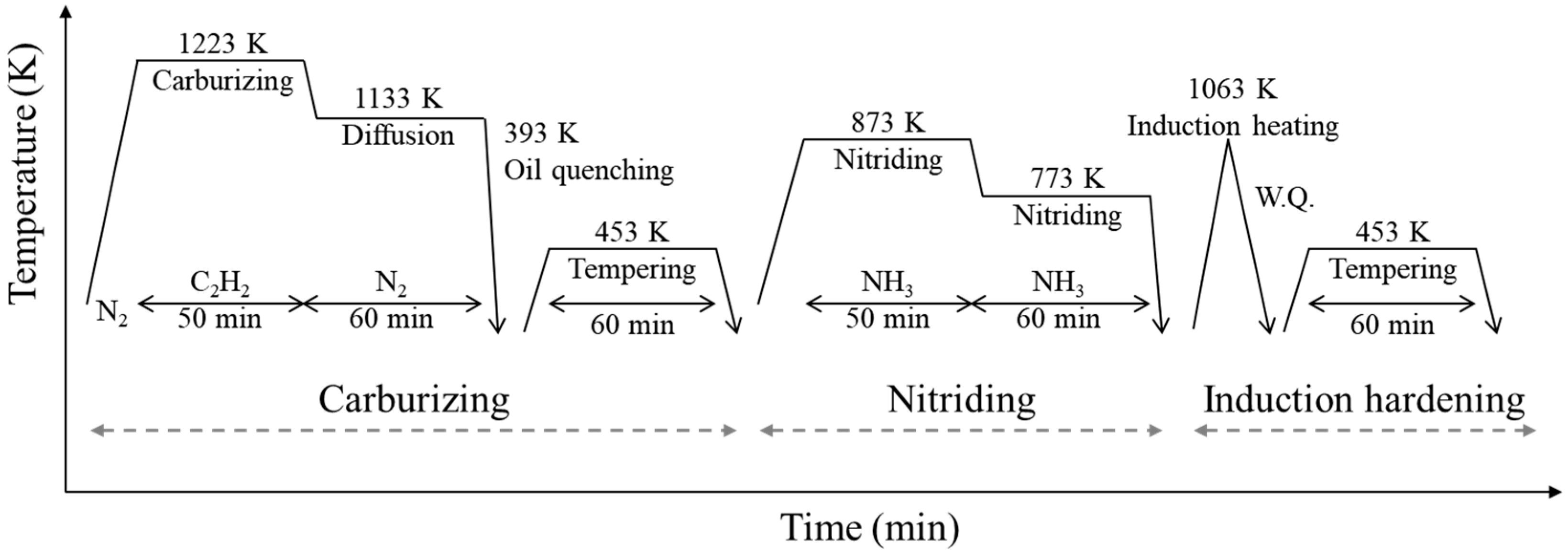
Figure 1. Schematic diagram of the carburizing and nitriding duplex treatment followed by induction hardening for IH specimens.
Metals 15 00944 g001
Figure 2. Carbon and nitrogen concentration–depth profiles in Non-IH and IH specimens.
Metals 15 00944 g002
Figure 3. OM micrographs of Non-IH (a) and IH (b) specimens.
Metals 15 00944 g003
Figure 4. (a) SEM image showing the microstructure of the IH specimen; magnified views of (b) the surface layer, (c) the interface between the diffusion layer and the core, and (d) the core region in (a).
Metals 15 00944 g004
Figure 5. (a) Inverse pole figure (IPF) map of the α-Fe (BCC) phase and (b) corresponding phase map obtained by EBSD analysis of IH specimens.
Metals 15 00944 g005
Figure 6. XRD patterns of the surface layers of the IH and BM (normalized test steel) specimens.
Metals 15 00944 g006
Figure 7. Hardness distribution from the surface to the core in the Non-IH and IH specimens.
Metals 15 00944 g007
Figure 8. Evolution of residual stress and retained austenite (γR) in the IH specimens before and after fatigue testing at a stress amplitude of σa =775 MPa.
Metals 15 00944 g008
Figure 9. S–N curves from plane-bending fatigue tests of the IH and NS specimens.
Metals 15 00944 g009
Figure 10. SEM fractography showing the fatigue fracture surfaces of the IH specimen tested at a stress amplitude of σa = 800 MPa and a cyclic life of Nf = 636,800: (a) overall fracture surface, (b) crack initiation region, (c) ECD region, (d) crack propagation region, and (e) final fracture region.
Metals 15 00944 g010
Disclaimer/Publisher’s Note: The statements, opinions and data contained in all publications are solely those of the individual author(s) and contributor(s) and not of MDPI and/or the editor(s). MDPI and/or the editor(s) disclaim responsibility for any injury to people or property resulting from any ideas, methods, instructions or products referred to in the content.