Article

A New Continuous Bending and Straightening Curve Based on the High-Temperature Creep Property of a Low-Alloy Steel Continuous Casting Slab

1
School of Machinery and Automation, Weifang University, Weifang 261061, China
2
National Engineering Research Centre for Equipment and Technology of Cold Strip Rolling, Yanshan University, Qinhuangdao 066004, China
*
Author to whom correspondence should be addressed.
Metals 2025, 15(9), 1059; https://doi.org/10.3390/met15091059
Submission received: 18 August 2025 / Revised: 16 September 2025 / Accepted: 18 September 2025 / Published: 22 September 2025

Abstract

The existing continuous caster layout curves cause plastic deformation of slabs during bending and straightening segments, while no effective deformation occurs in the basic arc segment, which tends to induce defects, such as cracks, and compromise slab quality. High-temperature creep deformation is generally regarded as detrimental to material performance. If the significant and inevitable creep deformation of a slab could be utilized to accomplish bending and straightening deformation during continuous casting, it would turn a potential harm into an advantage, ultimately enhancing both production efficiency and final product quality. Therefore, a new continuous bending and straightening curve based on the high-temperature creep property of a low-alloy steel slab was designed. The new curve cancelled the original basic arc segment and smoothly connected the bending and straightening segments, which not only substantially prolonged the effective bending and straightening deformation time but also extended the creep time. The locations within the slab corresponding to the temperature range of 1100 °C to 1200 °C were obtained from the simulated temperature field results. Comparing the calculated strain rates with the steady-state creep rates revealed that within the temperature range exhibiting favorable hot ductility, the bending and straightening deformation of the slab could be accomplished entirely through creep deformation.

1. Introduction

Continuous casting, a process where molten steel is solidified into shape through forced cooling and directly output as casting slabs [1], has become the globally dominant steel production technology. Its widespread adoption stems from significant advantages in efficiency, material yield, energy savings, and process simplification. In recent years, high-efficiency continuous casting has become a key research focus aimed at further enhancing casting efficiency, reducing production costs, and minimizing energy and resource consumption [2,3,4]. Within this process, bending and straightening constitute a critical stage, playing a vital role, as they directly influence the quality of the final casting slab product. In efforts to improve product quality, researchers have extensively studied crack formation in key sections of slabs during the continuous casting process [5,6,7,8].
Straightening refers to the process where a curved continuous casting slab undergoes plastic deformation under an external moment to become a straight slab [9]. During the process of slab straightening deformation, the initiation of an internal crack is directly related to its corresponding stress and strain state. Internal cracks form when the stress and strain at any location within the slab exceed their critical thresholds. Consequently, the development objective of straightening technology is to enhance continuous casting production efficiency while ensuring slab quality.
During the initial development of continuous casting technology, the relatively low slab withdrawal speeds resulted in prolonged residence times for a slab within both the bending segment and the basic arc segment. This extended cooling period meant the slab attained a fully solidified state before entering the straightening segment. For handling slabs in this fully solidified condition, the single-point straightening method was the initial straightening technique adopted in arc continuous casters. A significant drawback of the single-point straightening method was the pronounced peak strain concentrated at the single straightening point, resulting in a high strain rate within the slab. This elevated strain rate significantly increased the susceptibility to internal crack formation, thereby impeding quality improvement of the cast product. Consequently, researchers at the time implemented technological modifications in existing single-point straightening casters, aimed at mitigating the drawbacks of single-point straightening through process-based solutions [10,11]. In contrast to single-point straightening, multi-point straightening distributed the concentrated strain at multiple points. This distribution significantly reduced the strain imposed at each individual point, thereby lowering the susceptibility of the slab to internal crack formation [12]. However, when configuring the roller arrangement for multi-point straightening, although multiple curved segments were joined to form a visually smooth path, the curvature itself exhibited discontinuities at the connection points between segments. Abrupt changes in curvature still occurred at these locations [13,14]. Therefore, at the locations of abrupt curvature change, the risk of internal crack formation due to straightening deformation persisted. To address this, Voest-Alpine Industrieanlagenbau (VAI) developed an approach centered on defining a specific curve. Rollers were positioned along this curve, inducing gradual and continuous straightening deformation in the slab as it passed through them. This methodology aimed to reduce the strain rate during straightening, and the progressive straightening roller arrangement offered the additional benefit of improving the load distribution on the straightening rollers. Consequently, the technology was adopted by several domestic steel producers [15,16]. However, VAI did not disclose the precise mathematical definition of this roller arrangement curve, and a significant practical challenge arose from roller core misalignment during implementation, which could cause the actual strain experienced by the slab to exceed theoretical predictions. Compared with the progressive straightening method of VAI, Concast continuous straightening cancelled the transitional zones preceding and following the straightening segment. This simplification enhanced the structural efficiency of the roller arrangement. Li et al. [17] argued that the Concast continuous straightening curve could not be considered ideal because the curvature radius at the connection point between the Concast curve and the basic arc segment only approximated the basic arc radius when the arc length of the straightening segment was significantly shorter than the basic arc radius of the caster. If this condition was not met, an abrupt discontinuity in strain occurred when the slab transitioned from the basic arc segment to the straightening segment because of the inherent curvature mismatch. To address this, Li et al. [18] developed a modification of the Concast continuous straightening curve. They proposed an optimized cubic polynomial curve that guaranteed its curvature continuity with the basic arc segment of the caster at their connection point. This optimized cubic curve, serving as the straightening segment and smoothly connected to the basic arc segment, ensured the curvature variation rate was continuous, eliminating abrupt transitions. Building upon this foundation, Jing et al. [19,20] designed a novel continuous bending and straightening curve. The curve combined an involute segment and the optimized cubic polynomial curve, which were joined with curvature continuity. They successfully implemented this novel curve in the revamp of a vertical-arc type, multi-point bending and straightening slab caster and reported satisfactory operational results.
Conventional continuous bending and straightening processes typically rely on plastic deformation as their fundamental mechanism. However, this approach carries an obvious risk of crack formation within the solid–liquid mushy zone of the slab, ultimately compromising the quality of the final cast product. In actual continuous casting operations, molten steel begins to cool at approximately 1500 °C. Throughout a substantial portion of the casting process, the surface temperature of the slab remains around 1000 °C. Simultaneously subjected to bending and straightening forces under these high-temperature conditions, the slab exhibits pronounced creep behavior. Crucially, creep deformation constitutes irreversible permanent deformation, occurring even when the applied stress is below the material’s yield strength. Consequently, the significant influence of high-temperature creep must be explicitly considered in any study investigating slab bending and straightening deformation. Although some studies [21,22] incorporated the high-temperature creep behavior inherent to the continuous casting process, a critical limitation persisted, namely, the scarcity of experimental creep data at relevant temperatures. This data gap forced reliance on extrapolation methods to estimate creep parameters, significantly constraining the accuracy of models predicting slab deformation during straightening.
High-temperature creep is widely recognized as a critical factor influencing the service performance of materials. Previous studies [23,24,25,26,27] have primarily focused on the creep characteristics and microstructural evolution of various materials under elevated temperatures, with the aim of mitigating their detrimental effects in practical applications. However, Zhang et al. [28] leveraged the characterized high-temperature creep properties of Q345c steel to design a novel creep-based straightening curve. The core principle of this curve was to exploit creep deformation as the primary mechanism for achieving slab straightening. Inspired by this finding, high-temperature mechanical property and tensile creep testing of a low-alloy continuous casting slab were performed in our prior work [29]. Furthermore, the creep constitutive equation was fitted, and the associated microstructural evolution during creep deformation was elucidated. Building directly upon these foundational results, this paper first investigates the feasibility conditions for utilizing creep deformation to accomplish slab bending and straightening deformation. Second, it presents the design of a novel curve based on the R9300 vertical-arc five-point bending and five-point straightening continuous casting machine in Ansteel (Anshan, China). Finally, the performance of this curve is evaluated through numerical simulation to assess its capability for achieving complete creep-based bending and straightening.

2. Methodology

2.1. Parameters of the R9300 Continuous Casting Machine

The well-established engineering practice of the R9300 vertical-arc five-point bending and five-point straightening continuous casting machine in Ansteel makes its parameters a suitable reference for the present design. The caster has a slab section size of 1000 mm × 230 mm and a casting speed of 1.5 m/min. The main parameters are listed in Table 1.

2.2. Realization of Creep Bending and Straightening

Given the similar nature of the bending and straightening deformation processes in a continuous casting slab, this study uses straightening deformation as an example for illustration. A key factor affecting slab straightening deformation is the arrangement of roller rows in the straightening segment of the continuous caster. For a continuous casting slab with a liquid core that has not completely solidified during straightening deformation, the center of symmetry in the thickness direction is taken as the neutral layer. It is assumed that the neutral layer does not change during straightening deformation, as shown in Figure 1.
D is the thickness of the continuous casting slab (mm); h is the distance between a spot within the solidified shell and the slab surface (mm).
Therefore, the straightening strain can be expressed by Equation (1). This strain is defined for any two infinitely close positions along the straightening curve at a specific spot from the surface within the solidified shell of the slab.
ε p ,   p + 1 = D 2 h k p + 1 k p
where kp+1 and kp are curvatures of the continuous casting slab at any two infinitely close points along the straightening curve (mm−1) and ε p ,   p + 1 is the strain of the continuous casting slab along the straightening curve between any two infinitely close points. From this, the straightening strain between any two points along the continuous straightening curve can be obtained as Equation (2):
ε i , j = p = 1 n lim n ε p , p + 1 = p = 1 n lim n D 2 h k p + 1 k p
where ε i , j is the straightening strain of the continuous casting slab between any two spots along the straightening curve.
Because the curvature of the continuous straightening curve changes continuously, the straightening strain of the continuous casting slab also changes continuously. By applying Equation (2) to the limit of the straightening deformation time, the straightening strain rate of the continuous casting slab at any position along the straightening curve can be formulated as Equation (3):
ε ˙ i , j = lim t 0 Δ ε i , j Δ t
where ε ˙ i , j is the strain rate of the continuous casting slab at any position along the straightening curve (s−1); Δ ε i , j is the strain variation between any two points along the straightening curve; and Δ t is the time of straightening deformation (s).
When designing the continuous caster layout curve in practice, the curvature is usually expressed by the arc length. The arc length between any two infinitely close points along the straightening curve tends to be infinitely short, and the curvature can be differentiated from the arc length. In addition, the withdrawal speed of the continuous casting slab remains constant under the steady-state casting condition. Therefore, the strain rate of a specific spot from the slab surface inside the solidified shell, at any position of the straightening curve, can be expressed by the curve arc length as Equation (4):
ε ˙ s = lim Δ s 0 Δ ε i , j Δ s Δ s Δ t = V c D 2 h k s
where ε ˙ s is the strain rate in relation to the arc length at any spot inside the solidified shell (s−1); Δ s is the arc length variation (mm); V c is the withdrawal speed (mm/s); and k s is the change rate of curvature with respect to the arc length (mm−2).
Equation (4) implies that the straightening strain rate of the continuous casting slab is relatively small when the curvature variation rate of the straightening curve is small.
When the continuous casting slab is subjected to stress below its yield strength at a certain temperature, creep deformation and the corresponding creep rate ε ˙ c occur. Consequently, by comparing the values of the straightening strain rate ε ˙ s and creep rate ε ˙ c , the following relationship can be obtained:
When ε ˙ s > ε ˙ c , the straightening deformation of the continuous casting slab is completed by both plastic deformation and creep deformation.
When ε ˙ s < ε ˙ c , the straightening deformation of the continuous casting slab is achieved entirely by creep deformation, and the straightening stress is less than the yield strength of the material at the corresponding temperature.
Accordingly, it is necessary to find a continuous bending and straightening curve with a low curvature variation rate. This ensures that the strain rate of the continuous casting slab remains below its creep rate under the corresponding working conditions. Thereby, the creep deformation can be used to complete the bending and straightening deformation. The specific steps of this study are outlined in Figure 2.
In addition to meeting the characteristics of a low curvature variation rate, attention should also be paid to the curve arc length when designing a specific bending and straightening curve. On the premise of meeting the slab solidification conditions and specific metallurgical process parameters, if longer bending and straightening segments could be obtained, the creep deformation time could be extended, and the slab strain rate in bending and straightening segments could be reduced. When various curves are applied to the bending and straightening segments of a continuous caster, it is necessary to meet the specific model characteristics of the caster and the following boundary conditions:
(1)
The end of the straightening curve is tangent to the horizontal segment of the continuous caster, and the slope and curvature at the tangent point are zero.
(2)
If the initiation point of the straightening curve is connected to the basic arc segment of the continuous caster, the curvature radius at the connection point should be equal to the basic arc radius, and there should be a common tangent at the connection point.
(3)
If the basic arc segment is cancelled and the beginning of the straightening curve is directly connected to the end of the bending segment, then there should be an equal curvature radius and a common tangent at the connection point.

2.3. The Design of the New Curve

2.3.1. Quartic Even Polynomial Curve (Straightening Segment)

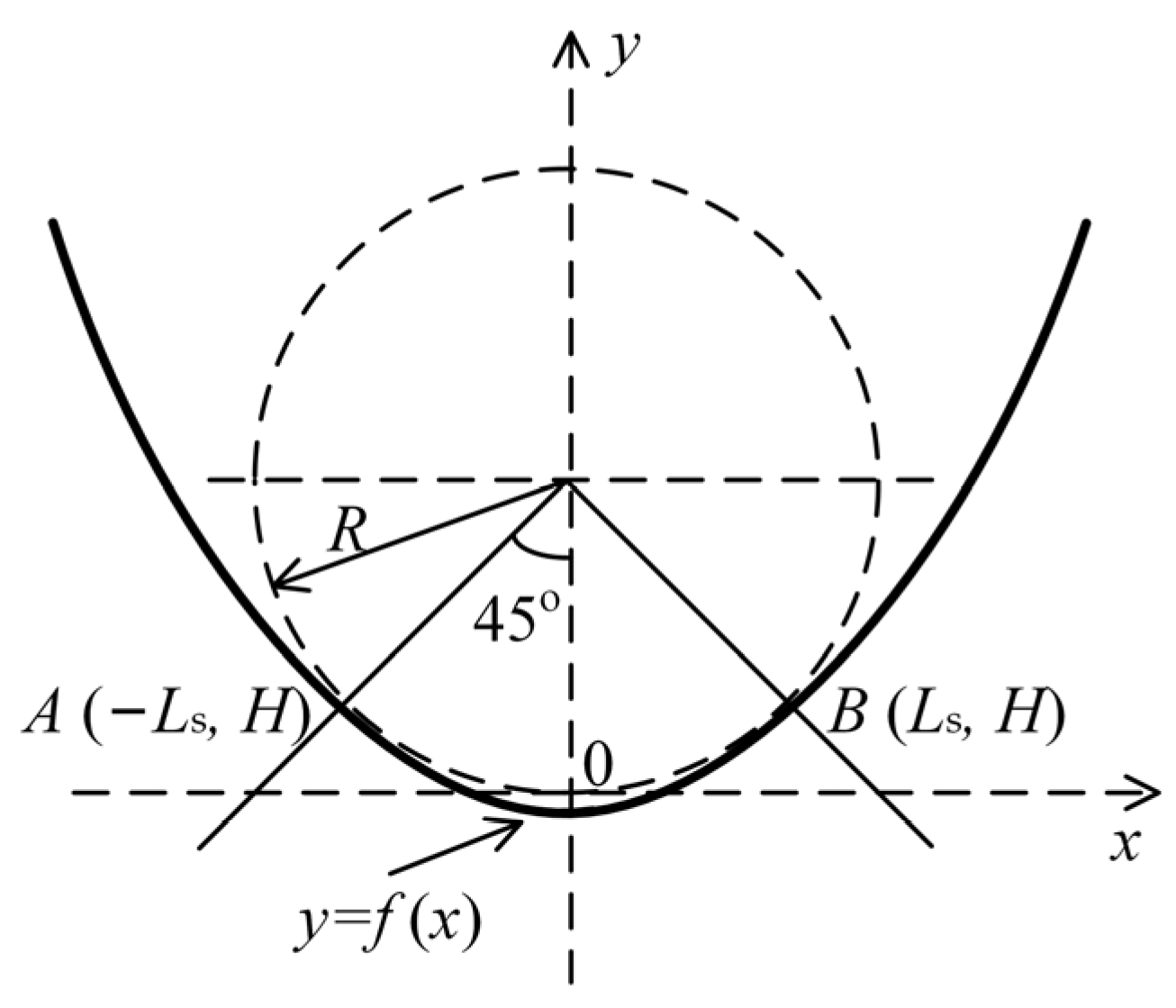
When the straightening segment curve is defined by a quartic even polynomial, the curve is symmetric about the y-axis. For ease of derivation, a schematic diagram is drawn in a rectangular coordinate system, as shown in Figure 3.
The general expression for this quartic even polynomial curve can be written as Equation (5):
y = a 0 x 4 + a 1 x 2 + a 2
where a0, a1, and a2 are all undetermined coefficients. Equation (5) could be further differentiated to obtain the first derivative, second derivative, and curvature of the curve, which are expressed in Equations (6)–(8):
y ( x ) = 4 a 0 x 3 + 2 a 1 x
y ( x ) = 12 a 0 x 2 + 2 a 1
k ( x ) = y ( x ) 1 + y 2 x 3 2 = 12 a 0 x 2 + 2 a 1 [ 1 + ( 4 a 0 x 3 + 2 a 1 x ) 2 ] 3 2
According to the even function property of Equation (5), the boundary conditions during the interval of x [−Ls, Ls] can be described as Equation (9):
y ( ± L s ) = H y ( ± L s ) = ± 1 k ( ± L s ) = 0
Therefore, the undetermined coefficients a0, a1, and a2 can be obtained, and by substituting them into Equation (5), the expression of the quartic even polynomial curve can be written as Equation (10):
y = 1 8 L s 3 x 4 + 3 4 L s x 2 + H 5 L s 8

2.3.2. Sinusoidally Varying Curvature Curve (Bending Segment)

When the curvature varies sinusoidally, it can be expressed as a function of arc length l:
k ( l ) = c 1 sin ( c 2 l ) + c 3
where c1, c2, and c3 are undetermined coefficients.
According to the curvature characteristics of the caster layout curve, the boundary conditions satisfied by the bending segment curve at the starting and connecting points are given by Equation (12):
k | l = 0 = 0 k | l = 0 = 0 k | l = L = 1 / R 0
From these boundary conditions, the undetermined coefficients c1, c2, and c3 can be determined from Equation (13):
c 1 = 1 / R 0 c 2 = π / ( 2 L ) c 3 = 0
Therefore, the expression of curvature with respect to arc length can be written as Equation (14):
k ( l ) = 1 R 0 sin π l 2 L   ( 0 l L )
According to the definition of curvature, the angle θ of the tangent at any point on a curve that varies sinusoidally can be expressed as Equation (15):
θ ( l ) = 0 l k ( l ) d l = 1 R 0 0 l sin π l 2 L d l = 2 L π R 0 1 cos π l 2 L
Then, based on the arc differentiation formula, the expression of the sinusoidally varying curvature curve with respect to arc length in a rectangular coordinate system can be obtained by integration, as formulated in Equation (16):
x ( l ) = 0 l cos θ ( l ) d l = 0 l cos 2 L π R 0 1 cos π l 2 L d l y ( l ) = 0 l sin θ ( l ) d l = 0 l sin 2 L π R 0 1 cos π l 2 L d l

2.3.3. Combination of Bending and Straightening Segments

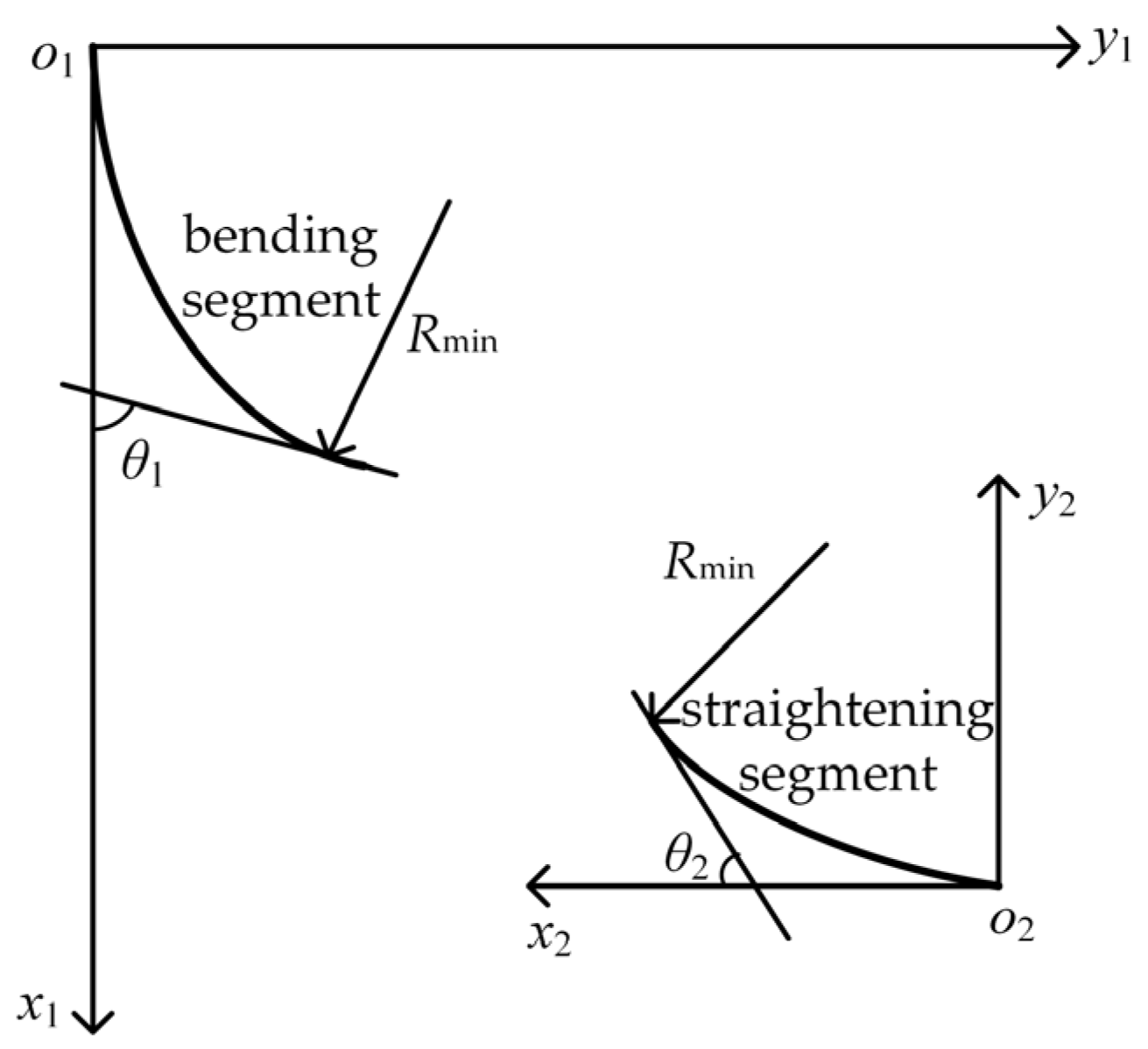
The new continuous bending and straightening curve formed by the smooth connection of the bending and straightening segments needs to satisfy the requirement that there is a common tangent at the connection point, where the curvature radius should be the smallest in the entire continuous casting machine. It is precisely because the two segments have a common tangent at the connection point that they can be combined by flipping and translating to smoothly connect in the same coordinate system, as shown in Figure 4.
In Figure 4, the bending segment is in the x1o1y1 coordinate system, and the straightening segment is located in the x2o2y2 coordinate system. To place both segments in the same coordinate system, such as the x1o1y1 coordinate system, the straightening segment needs to be flipped and translated to connect smoothly with the bending segment. The relationship between the tangent angles at their connection point is given by Equation (17):
tan θ 2 = tan π 2 θ 1
For traditional continuous casting machines with basic arc segments, the basic arc radius is usually calculated by the allowable surface deformation rate of the continuous casting slab during the casting process [30], as shown in Equation (18):
R 0 0.5 D ε 0
where R0 is the basic arc radius (mm); [ε0] is the allowable strain of the continuous casting slab surface, which is generally taken as 1.5~2.0% for ordinary carbon steel and low-alloy steel [31].
Therefore, for the continuous bending and straightening curve without a basic arc segment proposed in this article, the curvature radius at the connection point between the bending and straightening segments can be written as Equation (19):
R min 0.5 D ε 0
where Rmin is the minimum curvature radius at the connection point between the bending and straightening segments (mm).

3. Results

3.1. The Expression of the Continuous Bending and Straightening Curve

By substituting a slab thickness of 230 mm into Equation (19), the minimum curvature radius range of the bending and straightening segments at the connection point was calculated to be 5750~7666.66 mm.
Therefore, the curvature radius at the connection point was firstly set to 7000 mm. For the bending segment curve, which had a sinusoidally varying curvature, once the curvature radius at the connection point was fixed, only the arc length remained to be specified to uniquely define the curve. For the straightening segment curve defined by a quartic even polynomial, even-function characteristics were utilized. The tangent angle of the straightening segment curve at the connection point was set to π/4, and the corresponding tangent angle of the bending segment curve at the connection point was also π/4.
Furthermore, the arc length of the bending segment curve was calculated as 8636 mm. The expression for its curvature as a function of arc length could be written as Equation (20):
k 1 = 1 7000 sin π l 17,272 ( 0 l 8636 )
And the function for the arc length of the bending segment curve in the rectangular coordinate system x1o1y1 could be described as Equation (21):
x l = 0 8636 cos 8636 3500 π 1 cos π l 17,272 d l y l = 0 8636 sin 8636 3500 π 1 cos π l 17,272 d l
Similarly, for the straightening segment curve, the curvature at the connection point could be used to solve for Ls of 10,500 mm. And the formula of the straightening segment curve in the x2o2y2 coordinate system could be expressed as Equation (22):
y = 1 9.261 × 10 12 x 4 + 1 14,000 x 2 + H 13,125 2 0 x 10,500
The specific expressions for the bending and straightening segments were imported into MATLAB R2016a software. Using the property that the curvature at the connection point was equal, where the two segments also had a common tangent, the straightening segment curve was flipped and translated to smoothly connect to the bending segment curve in the x1o1y1 coordinate system. In addition, the coordinate matrix of the straightening segment curve could be obtained as described in Equation (23):
A 1 = cos π 4 sin π 4 0 sin π 4 cos π 4 0 0 0 1 1 0 0 0 1 255 0 0 1 x y 1
where A1 is the coordinates of the straightening segment curve of the combined bending and straightening curve.
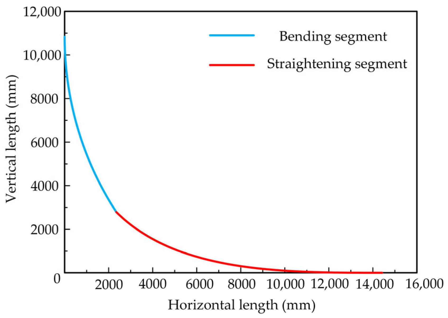
Consequently, the sinusoidal curvature–quartic even polynomial curve could be drawn as Figure 5.

3.2. Roller Arrangement of the New Curve

Based on the roller arrangement of the R9300 vertical-arc continuous casting machine, and with reference to the sizes of the roller diameter and the roller spacing, the original roller arrangement was adjusted to match the new sinusoidal curvature–quartic even polynomial continuous bending and straightening curve. The roller diameter ranges from 150 mm to 350 mm. The redesigned roller arrangement is illustrated in Figure 6.
It can be seen from Figure 6 that the newly designed continuous casting and straightening curve is mainly composed of four segments, namely, the vertical segment (AB segment, 1008 mm) after exiting the mold; the bending segment (BC segment, 8636 mm); the straightening segment (CD segment, 12,706 mm), and a part of the horizontal segment (DE segment).
Compared with the original layout curve of the R9300 vertical-arc continuous casting machine, the sinusoidal curvature–quartic even polynomial curve cancelled the basic arc segment and adopted a smooth connection between the bending and straightening segments. Although the overall height increased by 159.45 mm, the bending segment length increased by 7606 mm, and the straightening segment length increased by 11,186 mm. These extensions significantly prolonged the duration of bending and straightening deformation, allowing the slab to deform gradually throughout the entire process. This not only lowers the strain rate, reducing the risk of cracking, but also extends the time available for creep deformation. The longer duration allows the creep effect to be fully utilized, enabling the bending and straightening to be achieved primarily through creep.

3.3. The Curvature and Curvature Variation Rate of the New Curve

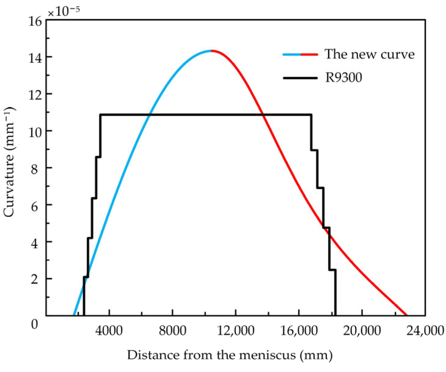
According to the roller arrangement of the new curve and the curvature calculation formula, the variation trend of the curvature with respect to the arc length could be obtained, which was also compared with the curvature of the original R9300 five-point bending and five-point straightening curve, as shown in Figure 7.
Figure 7 shows that the original curve of the R9300 continuous casting machine undergoes abrupt curvature changes at the bending and straightening points. Specifically, its curvature increases rapidly from zero to that of the basic arc over only five bending points, remains constant throughout the basic arc segment, and then decreases to zero over five straightening points. In contrast, the curvature of the new curve changes continuously with the arc length throughout the entire bending and straightening process, without any abrupt transitions. This continuous curvature variation is beneficial for reducing the possibility of internal cracks in the slab, thereby improving the quality of the final product.
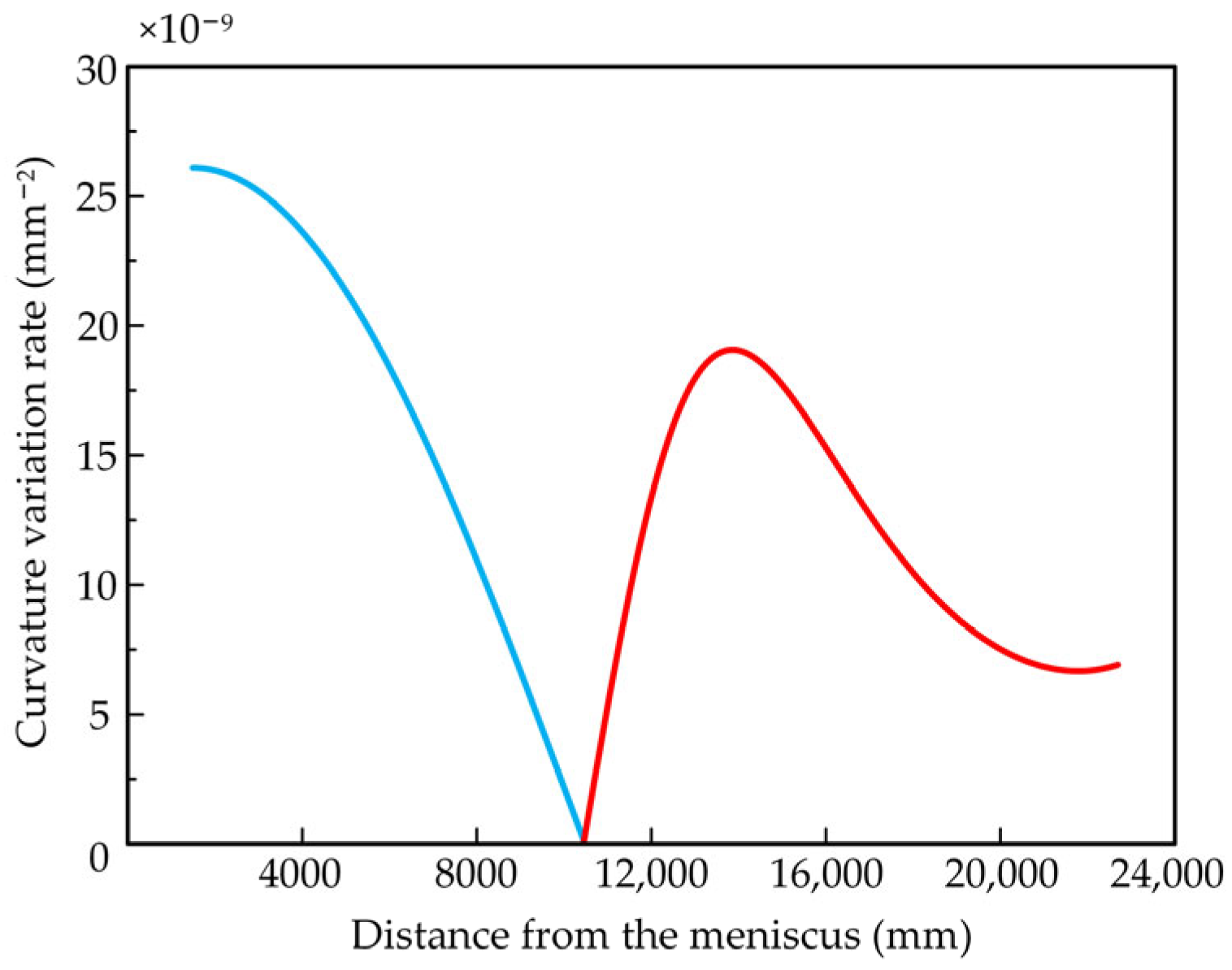
Additionally, the curvature variation rate of the new curve could be further obtained by taking the derivative of the curvature equation with respect to the arc length, as shown in Figure 8.
The curvature variation rate of the new curve begins to change at the start of the bending segment and reaches its maximum at the junction between the vertical and bending segments. It then gradually decreases to zero by the end of the bending segment. Similarly, the curvature variation rate of the straightening segment starts from zero, increases with arc length to the maximum value, and then gradually decreases until the end of the straightening segment. Throughout this process, the curvature variation rate changes continuously with arc length without any sharp transitions. The only exceptions are the junctions at the start of the bending segment and the end of the straightening segment, which undergo very small increases and decreases in the curvature variation rates, respectively. This continuous change indicates that when slabs deform along the new curve, internal cracks are less likely to form during bending and straightening, thereby improving the quality of the final product.

4. Discussion

4.1. Temperature Field Simulation of a Continuous Casting Slab Based on the New Curve

Based on the original R9300 five-point bending and five-point straightening continuous casting machine layout curve, a new sinusoidal curvature–quartic even polynomial continuous bending and straightening curve was developed, with its processing parameters listed in Table 2.
The cooling water distribution for the secondary cooling zone was based on the cooling loop layout of the original R9300 continuous casting machine. The new caster layout added 13 pairs of rollers compared with the original; therefore, the length of each cooling loop was adjusted based on the original. The specific cooling water distribution rule is shown in Table 3.
When the casting speed of the continuous caster is constant and all parameters are stable, a steady-state casting condition is achieved, and heat transfer along the casting direction can be ignored. Furthermore, the thin-slice method was adopted to model the continuous casting slab. In this model, the slab’s cross-section was represented by a thin slice that passed sequentially through the mold, secondary cooling zone, and air-cooling zone, as displayed in Figure 9.
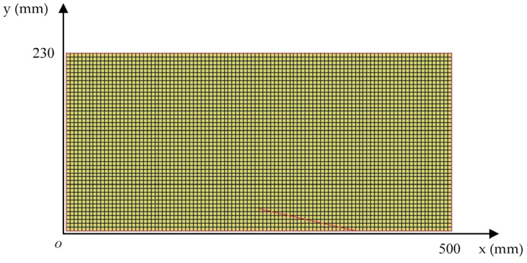
In addition, due to the symmetrical cooling boundary conditions, a half-cross-section model of the slab, whose size was 500 mm × 230 mm, was created in the finite element software MARC/Mentat 3.1. The model was divided into 100 parts horizontally and 46 parts vertically, resulting in 4600 elements, with dimensions of 5 mm × 5 mm, and 4747 nodes, as shown in Figure 10.
Steady-state casting was performed with an initial molten steel temperature of 1520 °C and a constant casting speed of 25 mm/s. As the slab was straightened upon exiting the secondary cooling zone before entering the air-cooling zone, the temperature field simulation covered the process from the entry of liquid steel into the mold to the completion of straightening as the slab exited the secondary cooling zone. Therefore, the boundary condition within the mold is usually expressed by an empirical formula [32] as follows:
q = 268 33.5 t
where q is the heat flux density of the mold at a certain moment (W/m2) and t is the casting time (s).
The boundary condition for the secondary cooling zone is given by the integrated heat flux density on the slab surface as Equation (25):
q c = h c T T w
where qc is the integrated heat flux density on the slab surface (W/m2); Tw is the temperature of cooling water (°C); and hc is the integrated equivalent heat transfer coefficient (W/(m∙°C)) usually determined by the volume of cooling water passing through a unit surface area of the slab per unit time, and expressed by an empirical formula [33] as Equation (26):
h c = 0.581 W c 0.451 1 0.0075 T w
where Wc is the cooling water flux (L/(m2∙s)).
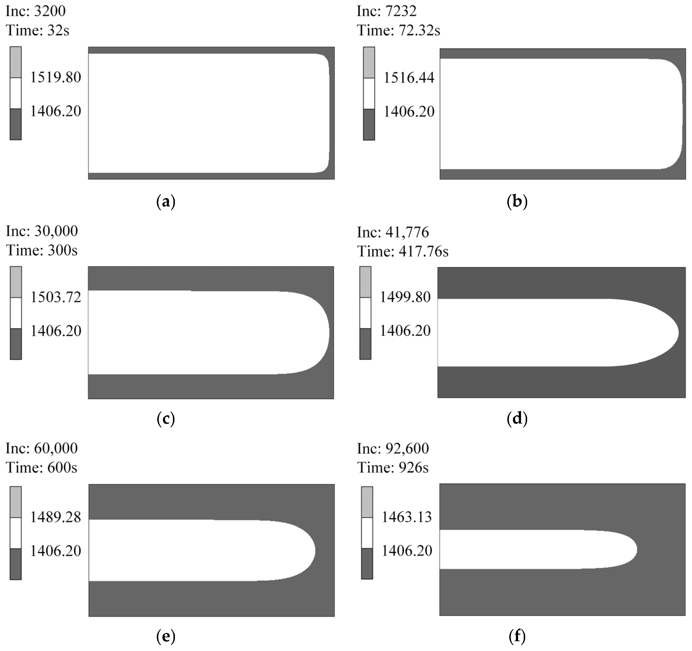
The computed temperature field within the transverse section of the slab at any given time corresponded to its spatial position along the caster and was determined by the elapsed time of movement. The history curve function in MARC/Mentat 3.1 software was used to post-process the temperature field simulation results and obtain the evolution of the slab shell thickness at different times based on the simulated temperature field and the material’s solidus temperature (1406.2 °C). Taking the shell thickness on the wide face as an example, Figure 11 depicts its variation at some specific instances during the solidification process.
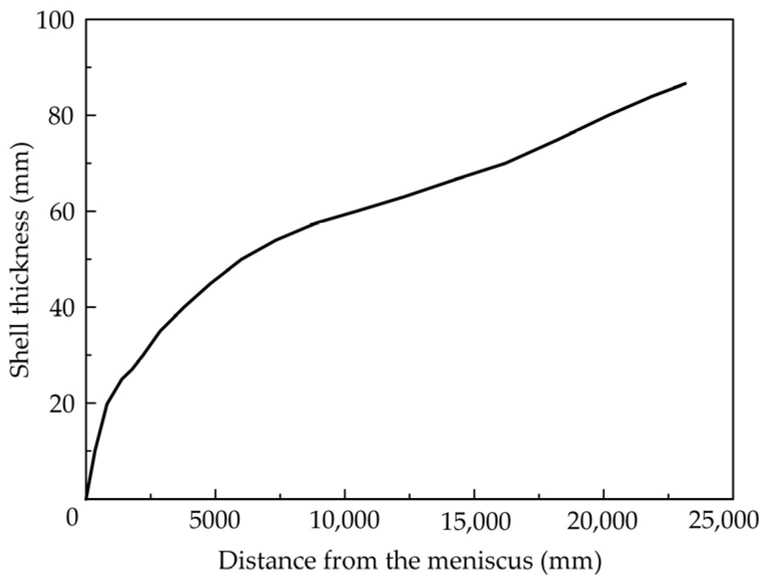
Figure 11 shows that the shell growth rate is rapid within the mold. Upon entering the secondary cooling zone, shell growth on the narrow face becomes slower compared to the wide face, due to more obvious reheating effects. Based on the wide face shell thickness at each time step, the variation curve of shell thickness versus distance from the meniscus was obtained, as illustrated in Figure 12.
As can be seen from Figure 12, the slab thickness at mold exit is approximately 20 mm. Subsequently, the growth in the shell thickness follows an exponential-like pattern. At the end of the bending segment, which coincides with the start of the straightening segment, the shell thickness reaches approximately 60 mm. By the end of the straightening segment, the shell thickness reaches 86.5 mm.

4.2. Calculation of the Strain Rate of the Continuous Casting Slab

Based on the temperature field simulation results, the distances from the upper surface to the locations where the slab temperature in the inner arc side reached 1100 °C, 1150 °C, and 1200 °C were determined. The values are summarized in Table 4.
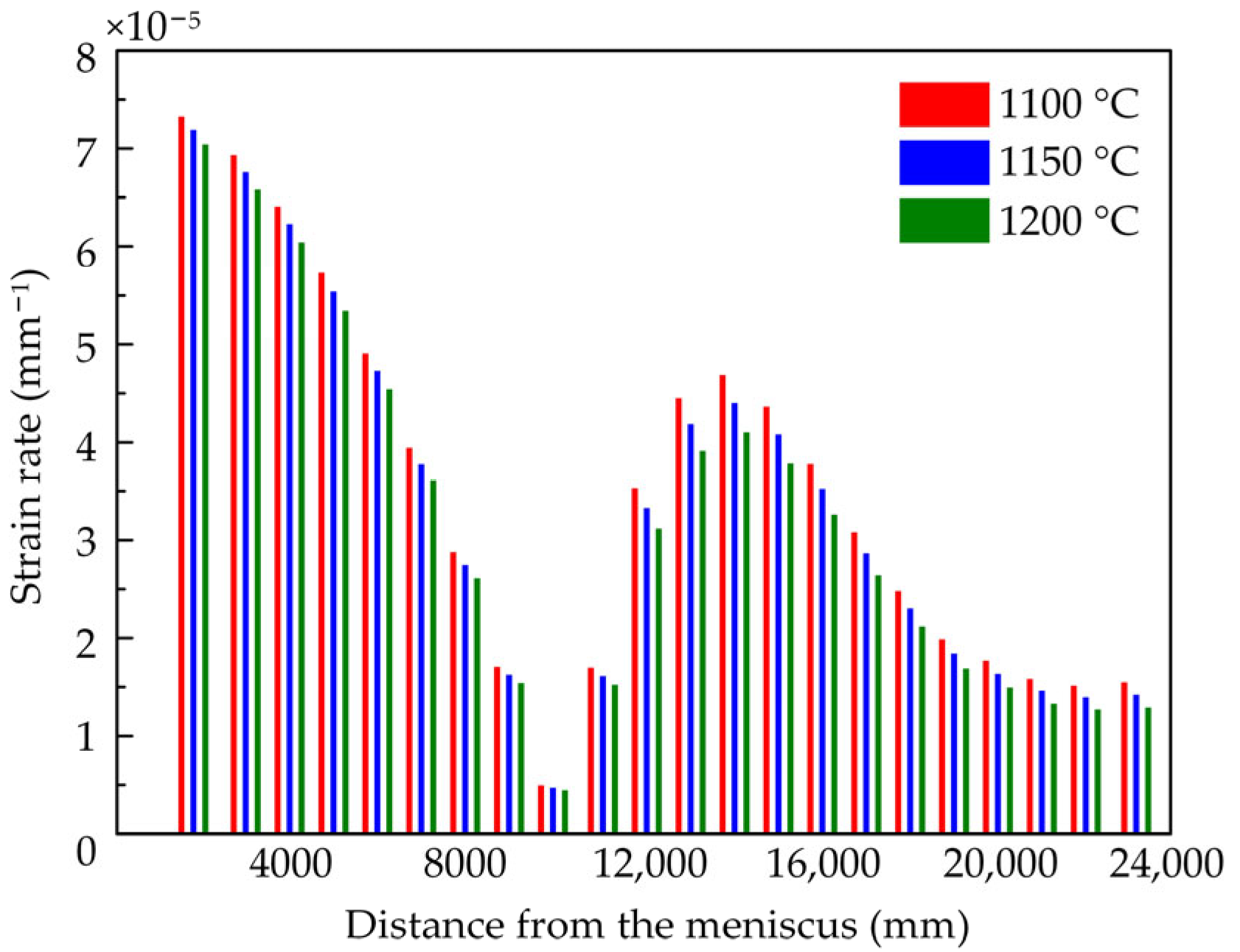
Using Equation (4) derived earlier in this paper, the strain rates at locations corresponding to temperatures of 1100 °C, 1150 °C, and 1200 °C in the slab inner arc side were calculated by substituting the curvature variation rate at different positions along the newly designed caster layout curve. The resulting strain rates are presented in Figure 13.
Figure 13 shows that the strain rate values of the slab exhibit identical trends across different temperatures, all aligning with the trend of the curvature variation rate along the new caster layout curve, as shown in Figure 6. During movement through the bending segment, at any given cross-section, the strain rate at a specific location in the inner arc side decreases with increasing temperature. This is because the slab temperature is relatively lower near the outer surface and higher near the liquid core. Furthermore, during the straightening deformation, the straightening forces applied by the rollers act directly on the slab surface. Consequently, the strain rate in the relatively cooler area is slightly higher than that in the relatively hotter area.
Our previous study [29] revealed that the area near the slab surface, characterized by relatively lower temperatures and higher stress levels, exhibits higher dislocation densities and a greater number of low-angle grain boundaries. Conversely, the area near the liquid core, experiencing relatively higher temperatures and lower stress levels, displays reduced dislocation densities and fewer low-angle boundaries. This indicates that the relatively cooler, higher-stress areas within the slab possess enhanced creep resistance. Consequently, these areas are more effective in utilizing creep deformation to accommodate the bending and straightening strains during continuous casting.

4.3. Verification of Creep Continuous Bending and Straightening

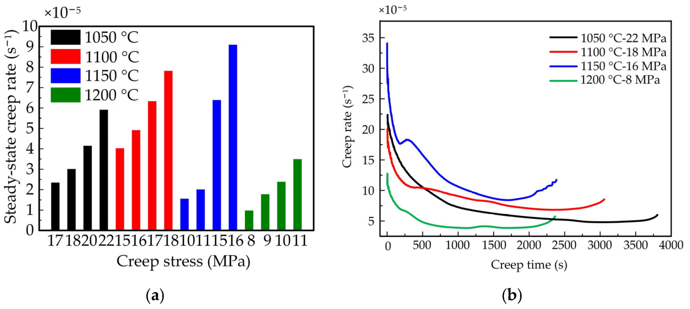
In our previous study [29], through high-temperature tensile creep tests, the steady-state creep rates and maximum creep rates under various testing conditions were obtained, as shown in Figure 14.
A comparison of the test data with the slab strain rates shows that the maximum slab strain rates in the bending and straightening segments are 7.32 × 10⁻⁵ s−1 and 4.68 × 10⁻⁵ s−1, respectively, at 1100 °C, which are both below the steady-state creep rate of 7.81 × 10⁻⁵ s−1 measured under the test condition of 1100 °C-18 MPa. Furthermore, the yield strength of this low-alloy steel at 1100 °C is 23.5 MPa; therefore, at locations within the slab where the internal temperature is 1100 °C, the bending and straightening deformation could be entirely completed by creep deformation. Similarly, the maximum slab strain rates in the bending and straightening segments are 7.19 × 10⁻⁵ s−1 and 4.40 × 10⁻⁵ s−1, respectively, at 1150 °C, which are both below the steady-state creep rate of 9.09 × 10⁻⁵ s−1 measured under the test condition of 1150 °C-16 MPa. The applied creep stress of 16 MPa is also below 17.5 MPa, which is the yield strength of this material at 1150 °C. Consequently, full creep deformation similarly governs the bending and straightening processes at slab locations with an internal temperature of 1150 °C.
However, at 1200 °C, the maximum slab strain rates in the bending and straightening segments are 7.04 × 10⁻⁵ s−1 and 4.10 × 10⁻⁵ s−1, respectively, which are both greater than the steady-state creep rate of 3.49 × 10⁻⁵ s−1 measured under the test condition of 1200 °C-11 MPa. Moreover, the yield strength of the material at 1200 °C is only 12.3 MPa; therefore, the minimum creep rate under the stress below the yield strength would not be greater than the maximum slab strain rate in the bending segment. Consequently, creep deformation can only accommodate a portion of the bending and straightening strains, and full accomplishment of the entire bending and straightening process via creep deformation is unattainable. In addition, high-temperature tensile ductility tests from the previous study [29] found that the low-alloy steel exhibits poor hot ductility at 1200 °C. This inherent mechanical property also contributes to the inability to achieve complete bending and straightening solely through creep deformation.

5. Conclusions

A new continuous bending and straightening curve based on the high-temperature creep property of a low-alloy steel continuous casting slab was designed. The main conclusions are summarized as follows:
  • The establishment condition of utilizing the high-temperature creep property of the continuous casting slab to achieve its bending and straightening deformation was derived, namely, that a position within the solidified shell could undergo bending and straightening deformation through creep deformation when the local strain rate at that position is less than the local steady-state creep rate.
  • Based on the existing R9300 vertical-arc continuous caster, the newly designed caster layout curve integrated a bending segment curve, whose curvature varied sinusoidally, and a straightening segment curve, which varied according to a quartic even polynomial. These segments were smoothly connected to form a continuous bending and straightening caster layout curve, whose curvature and curvature variation rate are continuous. Although the new caster layout curve increased the overall height by 159.45 mm, it significantly extended the bending segment by 7606 mm and the straightening segment by 11,186 mm. The newly designed curve not only substantially prolonged the effective duration for bending and straightening deformation, thereby reducing associated strain rates, but also extended the time available for creep deformation. Consequently, the role of creep deformation could be more effectively exploited.
  • From the simulated temperature field results, the locations within the continuous casting slab corresponding to the temperature range of 1100 °C to 1200 °C were identified. A comparison of the calculated strain rates with the steady-state creep rates obtained from high-temperature tensile creep tests revealed that within the temperature range exhibiting favorable hot ductility, the bending and straightening deformation of the slab could be accomplished entirely through creep deformation. However, at some locations of 1200 °C, where hot ductility is relatively poor, bending and straightening deformation could be partially achieved by creep deformation. This partial contribution of creep deformation also aided in reducing the magnitude of the bending and straightening forces, thus reducing the probability of crack formation and thereby enhancing the quality of the final casting product.
This study lays the foundation for future work, which will involve the design and quantitative comparison of multiple curves, followed by industrial verification to transition the theoretical framework into practical, validated solutions.

Author Contributions

Conceptualization, Y.S. and X.Z.; methodology, Y.S. and X.Z.; software, H.L.; validation, Y.S. and H.L.; formal analysis, Y.S.; investigation, H.L.; resources, H.L.; data curation, Y.S.; writing—original draft preparation, Y.S.; writing—review and editing, Y.S. and H.L.; visualization, H.L.; supervision, X.Z.; project administration, X.Z.; funding acquisition, Y.S. All authors have read and agreed to the published version of the manuscript.

Funding

This research was funded by Weifang University PhD research start-up Foundation, grant number 2023BS34.

Data Availability Statement

The original contributions presented in this study are included in the article. Further inquiries can be directed to the corresponding author.

Conflicts of Interest

The authors declare that they have no known competing financial interests or personal relationships that could have appeared to influence the work reported in this paper. The authors declare no conflicts of interest.

References

  1. Luo, X.; Xie, Q.; Wang, Y.; Yang, C. Estimation of heat transfer coefficients in continuous casting under large disturbance by Gaussian kernel particle swarm optimization method. Int. J. Heat Mass Tran. 2017, 11, 1087–1097. [Google Scholar] [CrossRef]
  2. Qiu, D.; Zhang, Z.; Li, X.; Lv, M.; Mi, X.; Xi, X. Numerical simulation of the flow field in an ultrahigh-speed continuous casting billet mold. Metals 2023, 13, 964. [Google Scholar] [CrossRef]
  3. Pang, X.; Li, H.; Wang, J.; Zhu, L.; Sun, L. Optimization of billet tube mold designs for high-speed continuous casting. Processes 2023, 11, 3367. [Google Scholar] [CrossRef]
  4. Sun, L.; Li, H.; Song, Z.; Guo, G.; Wang, C.; Matsveichuk, N.M.; Sotskov, Y.N. A review of dynamic flexible regulation strategies for multi-energy coupled steelmaking-continuous casting production. Eng. Appl. Artif. Intel. 2025, 160, 111799. [Google Scholar] [CrossRef]
  5. Ai, S.; Long, M.; Yang, X.; Chen, D.; Xu, P.; Duan, H. Prediction model for crack sensitive temperature region and phase fractions of slab under continuous casting cooling rates based on finite element number of experiments. J. Mater. Res. Technol. 2023, 22, 1103–1117. [Google Scholar] [CrossRef]
  6. Yang, J.; Zhang, F.; Li, J.; Liu, W.; Wang, T.; Yuan, H.; Cang, D. Bending and straightening of a medium carbon steel continuous casting slab with low temperature end plastic groove. Materials 2022, 15, 2609. [Google Scholar] [CrossRef]
  7. Zhou, Q.; Yin, Y.; Liu, Z.; Zhang, J.; Zhang, J. Research mechanism of formation on transverse corner cracks in the continuous casting slab of peritectic steel. Steel Res. Int. 2022, 93, 2200336. [Google Scholar] [CrossRef]
  8. Zhang, Z.; Ji, C.; Ju, J.; Li, K.; Zhu, M. Micromechanical behavior and microcrack evolution in continuous casting slab: Experimental characterization, multiscale simulation and industrial validation. J. Mater. Process Tech. 2025, 340, 118866. [Google Scholar] [CrossRef]
  9. Luo, Z. Steelmaking Machinery, 2nd ed.; Metallurgical Industry Press: Beijing, China, 1989; p. 220. [Google Scholar]
  10. Cheng, N.; Wang, H. Investigation and practice on single-point straightening caster with liquid core straightening. Continuous casting. Cont. Cast. 2005, 2, 29–31. [Google Scholar]
  11. Sun, L.; Liu, Y.; Ren, Y.; Liu, Z.; Zhu, L. Research on solidification behavior and process optimization in single point straightening rectangular billet continuous casting for 65Mn steel. Iron Steel Vanadium Titan. 2015, 36, 120–125. [Google Scholar]
  12. Xing, G.; Zhu, M.; Lin, Q.; Liu, X. Finite element simulation of stress and strain of concasting slab during straightening. Spec. Steel 2006, 27, 10–12. [Google Scholar]
  13. Zhou, L. Design & calculation of multipoint straightening. CFHI Technol. 2009, 6, 10–12. [Google Scholar]
  14. Deisinger, M.; Tacke, K.H. Unbending of continuously cast slabs with liquid core. Ironmak. Steelmak. 1997, 24, 321–328. [Google Scholar]
  15. Wu, J.; Du, S. Application of VAI high-efficiency billet caster technology in Maanshan steel. Cont. Cast. 2004, 6, 23–24. [Google Scholar]
  16. Wang, M.; Hu, L.; Yan, Z.; Tian, X.; Su, Q. Production practice of steel continuous casting machine introduced by VAI. Iron Steel 2004, 39 (Suppl. S1), 173–175. [Google Scholar]
  17. Li, X.; Shi, C. Improvement of Concast continuous straightening curve. Chin. J. Mech. Eng. 1996, 32, 106–110. [Google Scholar]
  18. Li, X. Low-head continuous casting machine with two smooth continuous straightening areas. Iron Steel 1996, 31, 31–35. [Google Scholar]
  19. Jing, F.; Li, X.; Yang, L.; Sun, H.; Wang, T.; Chen, Z. Optimization of continuous bending and straightening curve of vertical-arc slab caster. Iron Steel 2009, 44, 23–27. [Google Scholar]
  20. Jing, F.; Li, X.; Wang, T.; Chen, Z.; Sun, H. Research and application of strand’s new-ideal continuous straightening curve. China Mech. Eng. 2009, 20, 1240–1244. [Google Scholar]
  21. Jing, F.; Zhang, X.; Meng, J.; Guo, W. Analysis of the numerical solution to the ideal straightening curve equation of continuous casting slab. Heavy Mach. 2004, 3, 49–52. [Google Scholar]
  22. Wang, T.; Chen, Z.; Li, X.; Man, Y. Application of continuous straightening on slab casting. Cont. Cast. 2007, 5, 9–11. [Google Scholar]
  23. Liu, C.; Gadelmeier, C.; Lu, S.; Yeh, J.; Yen, H.; Gorsse, S.; Glatzel, U.; Yeh, A. Tensile creep behavior of HfNbTaTiZr refractory high entropy alloy at elevated temperatures. Acta Mater. 2022, 237, 118188. [Google Scholar] [CrossRef]
  24. Dong, S.; Gong, Z.; Chen, Z.; Qu, Y.; Chen, R.; Liu, S.; Li, G. High temperature tensile creep behavior and microstructure evolution of Ti60 alloy rolled sheet. Mater. Today Commun. 2024, 41, 110805. [Google Scholar] [CrossRef]
  25. Wang, T.; Kai, X.; Huang, L.; Peng, Q.; Sun, K.; Zhao, Y. High temperature creep behavior and creep mechanism of in situ (ZrB2+Al2O3)np/7055 Al nanocomposites. J. Alloys Compd. 2024, 981, 173662. [Google Scholar] [CrossRef]
  26. Pan, X.; Jia, C.; Qiu, C. On the high-temperature creep and fatigue behaviours of an advanced hot-extruded nickel-based alloy. Mater. Des. 2025, 257, 114514. [Google Scholar] [CrossRef]
  27. Gai, Y.; Zhang, R.; Cui, C.; Zhou, Z.; Tao, X.; Tan, Y.; Zhou, Y. Creep behavior and microstructure evolution of a novel Ni-Co-based superalloy with long-life designed for high temperature application. Mat. Sci. Eng. A 2025, 935, 148396. [Google Scholar] [CrossRef]
  28. Zhang, X.; Guo, L. Creep straightening technology of continuous casting slab based on high-temperature creep property. ISIJ Int. 2017, 57, 76–83. [Google Scholar] [CrossRef]
  29. Sui, Y.; Zhang, H.; Zhang, X. Study on the creep behavior and microstructure evolution of a low alloy steel in continuous casting processing. Mat. Sci. Eng. A 2022, 838, 142828. [Google Scholar] [CrossRef]
  30. Han, Z.; Feng, K.; Qu, T.; Cao, J.; Ren, B.; Mao, J. The discussion about the determination of basic radius for extra-thick slab caster. Ind. Heat. 2013, 42, 19–21. [Google Scholar]
  31. Chen, C.; Zhang, J. Determination of reasonable basic arc radius for bloom casters. Heavy Mach. 2010, S1, 119–124. [Google Scholar]
  32. Savage, J.; Pritchard, W. The problem of rupture of the billet in the continuous casting of steel. J. Iron Steel Inst. 1954, 178, 269–277. [Google Scholar]
  33. Sun, J. Heat Transfer Analysis in the Continuous Casting and Rolling Process; Metallurgical Industry Press: Beijing, China, 2010; pp. 93–94. [Google Scholar]
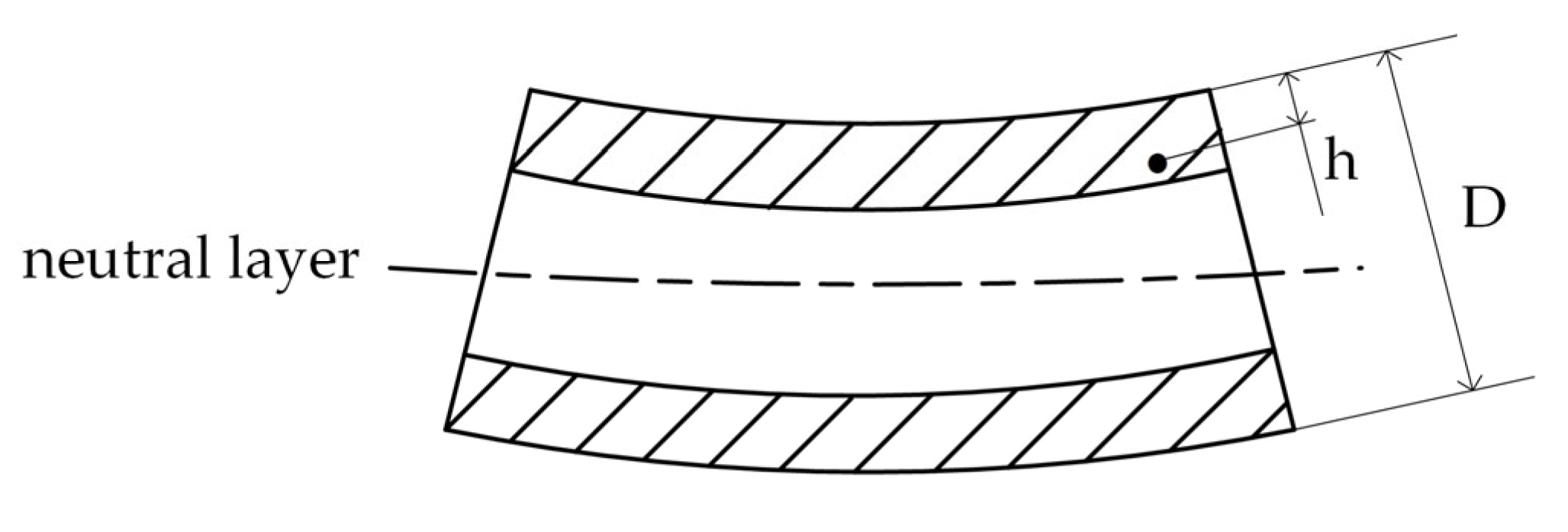
Figure 1. Schematic diagram of a casting slab cross-section.
Metals 15 01059 g001
Figure 2. Flowchart of the creep-based bending and straightening curve design steps.
Metals 15 01059 g002
Figure 3. The curve of a quartic even polynomial.
Metals 15 01059 g003
Figure 4. The combined bending and straightening curves in the same coordinate system.
Metals 15 01059 g004
Figure 5. The combined continuous bending and straightening curve.
Metals 15 01059 g005
Figure 6. The roller arrangement of the sinusoidal curvature–quartic even polynomial continuous bending and straightening caster layout curve.
Metals 15 01059 g006
Figure 7. The curvature comparison between the new continuous bending and straightening curve and the R9300 five-point bending and five-point straightening curve.
Metals 15 01059 g007
Figure 8. The curvature variation rate of the new caster layout curve.
Metals 15 01059 g008
Figure 9. The continuous casting slab: (a) three-dimensional slab along the casting direction; (b) thin cross-section of the two-dimensional model.
Metals 15 01059 g009
Figure 10. Finite element model of half of the continuous casting slab cross-section.
Metals 15 01059 g010
Figure 11. Shell thickness at different moments: (a) mold exit; (b) onset of bending; (c) a specific moment during bending; (d) completion of bending (onset of straightening); (e) a specific moment during straightening; (f) completion of straightening.
Metals 15 01059 g011
Figure 12. Shell thickness of the continuous casting slab during the solidification process.
Metals 15 01059 g012
Figure 13. Strain rates of the continuous casting slab along the new caster layout curve at 1100~1200 °C.
Metals 15 01059 g013
Figure 14. Creep rate (a) of steady state under various test conditions and (b) of maximum creep stress under corresponding testing temperature.
Metals 15 01059 g014
Table 1. Layout dimensional parameters of the R9300 continuous casting machine.
ParametersValue (mm)
Vertical segment1465
Bending segment1030
Basic arc length13,300
Straightening segment1520
Basic arc radius9300
Thickness of slab230
Metallurgical length35,862
Continuous casting machine height12,305.55
Curvature radius of roller No. 7 in bending segment49,420.83
Curvature radius of roller No. 8 in bending segment24,328.14
Curvature radius of roller No. 9 in bending segment15,971.29
Curvature radius of roller No. 10 in bending segment11,797.72
Curvature radius of roller No. 51 in straightening segment11,312.89
Curvature radius of roller No. 52 in straightening segment14,671.99
Curvature radius of roller No. 53 in straightening segment21,396.38
Curvature radius of roller No. 54 in straightening segment41,581.55
Table 2. Processing parameters of the new caster layout curve.
ParametersValue
Cross-sectional size of the slab (mm × mm)1000 × 230
Casting speed (mm/s)25
Casting temperature (°C)1520
Casting machine height (mm)12,465
Valid length of the mold (mm)800
Length of the secondary cooling zone (mm)22,350
Table 3. Secondary cooling schedule of the sinusoidal curvature–quartic continuous bending and straightening caster layout.
Cooling LoopCooling ZoneCooling LocationCooling Water Volume
(L/min)
1Foot roller after mold (F1)Wide side: in and out126
2Narrow side: left and right17.5
3No.1-No.7 roller pair
segment
Wide side: in and out554.4
4Narrow side: left and right108.5
5No.8-No.13 roller pair
segment
Wide side: in and out184.8
6Narrow side: left and right3.83
7No.14-No.19 roller pair
segment
Wide side: in and out109.2
8Narrow side: left and right3.83
9No.20-No.31 roller pair
segment
Wide side: in and out112
10Narrow side: left and right3.83
11No.32-No.44 roller pair
segment
Wide side: in and out84
12Narrow side: left and right3.83
13No.45-No.58 roller pair
segment
Wide side: in and out92.4
14Narrow side: left and right3.83
15No.58-No.68 roller pair
segment
Wide side: inner arc91.8
16Wide side: outer arc91.8
Table 4. The distance from the upper surface in the inner arc of the slab at 1100~1200 °C.
Distance from the Meniscus (mm)Distance from the Upper Surface in the Inner Arc of the Slab (mm)
1100 °C1150 °C1200 °C
18082.224.316.60
30005.568.2911.09
40007.7310.7013.84
50009.0012.5816.23
60009.9313.7317.73
700010.5714.9619.43
800010.6515.3920.28
900011.4516.3821.52
10,00012.5817.6222.91
11,00012.8218.1823.60
12,00013.4119.2225.27
13,00014.1120.1126.32
14,00015.1321.2127.61
15,00015.8922.3229.02
16,00016.6423.2730.12
17,00017.6324.3831.48
18,00018.6225.4932.73
19,00019.6426.6433.98
20,00020.8027.9735.40
21,00021.9229.1736.78
22,00022.7029.8437.50
23,15023.9531.3739.10
Disclaimer/Publisher’s Note: The statements, opinions and data contained in all publications are solely those of the individual author(s) and contributor(s) and not of MDPI and/or the editor(s). MDPI and/or the editor(s) disclaim responsibility for any injury to people or property resulting from any ideas, methods, instructions or products referred to in the content.