Article

Characterization of the Carbides in Carburized CSS-42L Steel and Their Effect on the Fatigue Failure Mechanism

1
School of Materials Science and Engineering, Harbin Institute of Technology, Harbin 150001, China
2
AECC Harbin Bearing Co., Ltd., Harbin 150025, China
3
Shenyang National Laboratory for Materials Science, Institute of Metal Research, Chinese Academy of Sciences, Shenyang 110016, China
*
Author to whom correspondence should be addressed.
Metals 2025, 15(9), 1013; https://doi.org/10.3390/met15091013
Submission received: 10 August 2025 / Revised: 4 September 2025 / Accepted: 9 September 2025 / Published: 11 September 2025

Abstract

The types of carbides and their effects on the fatigue failure mechanism in carburized CSS-42L steel were systematically studied in the present investigation. The results indicate that the main carbides in carburized CSS-42L steel are Cr-rich M23C6 carbides and Mo-rich M6C carbides. M23C6 carbides precipitate along grain boundaries and interconnect, forming network carbides. Rolling contact fatigue (RCF) tests reveal that fatigue cracks in CSS-42L steel can initiate both at the contact surface and within the subsurface. During RCF, the spalling of large-sized, networked M23C6 carbides creates micro-spalling pits on the contact surface, inducing local stress concentration that triggers the initiation of surface cracks. The surface cracks initially propagate perpendicularly to the contact surface and then shift to propagate parallelly to the contact surface, ultimately causing large-scale spalling of the surface layer. Subsurface cracks initiate at a position approximately 100 μm below the contact surface, with their propagation direction roughly parallel to the contact surface. Meanwhile, the development of subsurface cracks can connect with surface cracks, leading to the expansion of surface micro-pitting. Network carbides facilitate the propagation of secondary cracks, leading to the formation of grid-distributed crack networks.

1. Introduction

The rapid advancement of aerospace technology has imposed increasingly stringent requirements on the comprehensive performance of critical component materials [1,2,3,4,5,6]. As core supporting elements in high-load rotating components such as engines, transmission systems, and landing gear, aerospace bearings directly determine aircraft service safety and operational efficiency [7]. Early aerospace bearing steels were primarily based on high-carbon chromium steel [8,9,10,11]. However, with the evolution of aviation power systems toward higher thrust-to-weight ratios, ultra-high rotational speeds (e.g., turbine speeds exceeding 20,000 rpm), and extreme temperature environments (−60 °C to 300 °C) [12,13], traditional bearing materials have shown vulnerabilities under the coupled effects of complex alternating stresses, high-temperature oxidation, and fretting wear. They frequently experience fatigue spalling and dimensional instability, which severely constrain engine lifespan and energy efficiency [1]. Thus, aerospace bearing steels must simultaneously meet the following requirements: an ultra-high strength–toughness balance (with tensile strength ≥ 2000 MPa and fracture toughness KIC > 30 MPa·m1/2), superior rolling contact fatigue (RCF) resistance (service life > 108 cycles), excellent high-temperature softening resistance (>90% hardness retention at 300 °C), and outstanding environmental corrosion resistance [2]. Given the urgent demand for bearing steels in new-generation aero-engines, many recent research has focused on developing third-generation aerospace bearing steels and their surface modification technologies. This effort aims to push the boundaries of material performance to meet the growing demands for extended service life, enhanced reliability, and lightweight design in next-generation aerospace equipment.
CSS-42L steel is a case-hardening bearing steel developed by Latrobe Special Steel Company of the United States [14]. This steel is manufactured via a dual-vacuum process combining vacuum induction melting (VIM) and vacuum arc remelting (VAR), thereby achieving ultra-high steel purity and ultra-low inclusion content [15]. As a part of the third-generation bearing steels, CSS-42L is designed for bearing applications in complex environments, with its most notable advantage being high-temperature performance-retaining service up to 500 °C. This steel can achieve room temperature hardness of 67–72 HRC and high-temperature hardness of 58 HRC at 500 °C [16,17]. The RCF performance of CSS-42L steel is also significantly superior to that of M50 steel (a kind of the second-generation aerospace bearing steel currently in widespread use). RCF tests conducted by Burrier et al. [15] indicated that the basic rating life (L10) of CSS-42L reached 86.3 h while the basic rating life (L10) of M50 steel is only 3.5 h. Post-test SEM analysis also revealed minimal surface wear on CSS-42L specimens. Comparative studies by Tomasello C M et al. [14] further confirmed the RCF life of CSS-42L compared to competing bearing materials, highlighting its exceptional durability in high-stress applications. The excellent service performance of CSS-42L steel is primarily attributed to the high-density of precipitations [18,19,20,21]. However, the high content of alloying elements also causes the precipitation of numerous coarse carbides in CSS-42L steel during carburizing; in severe cases, network carbides even form along grain boundaries, which severely impairs the fatigue performance of CSS-42L bearing steel. This has become the key factor restricting the application of CSS-42L steel.
RCF represents one of the most severe service conditions in engineering systems [22,23,24,25,26,27]. Typically, RCF manifests through two primary failure modes: Surface-Originated Pitting (SOP) and Subsurface-Originated Spalling (SOS). Surface Failure Drivers [28] include high surface friction, suboptimal surface finish, and inadequate lubrication [8,9,29,30]. Even in properly installed rolling element bearings (REBs) operating under conditions of clean lubrication and regular maintenance, SOS failures still occur frequently. Subsurface fatigue originates from cyclic contact stresses. RCF resistance is governed by material microstructure, as cracks nucleate near stress concentrations below the contact zone. Networked carbides in the carburized layer intensify stress concentration. These carbides endure cyclic stresses, accelerating fatigue crack propagation. Meanwhile, carbides act as the stress–strain governing phase during the process of subsurface microstructure degradation. Under rolling contact conditions, phenomena such as the formation of butterfly WEA induced by carbides [31,32], the capture of hydrogen atoms by carbides altering dislocation mobility, and the initiation and propagation of cracks all significantly influence the occurrence of rolling contact fatigue [33,34]. This failure mechanism underscores the crucial necessity of controlling carbide morphology in the design of advanced bearing steels.
This study systematically characterized the types of carbides in carburized CSS-42L steel and revealed their effect on the fatigue failure mechanism during RCF. The crystal structure and distribution of different carbides were characterized by SEM and TEM. The surface morphology, spalling pit features, and microstructure evolution in the subsurface of specimens after RCF testing were all characterized in detail to clarify the fatigue failure mechanism induced by large-sized carbides.

2. Material and Experimental Procedure

2.1. Material

The experimental steel used in this investigation was CSS-42L steel produced by VIM and VAR. The chemical composition (in wt.%) is presented in Table 1. The as-received steel was a steel bar with a diameter of 60 mm after annealing treatment. RCF test specimens were cut from the 1/2 radius of the steel bar and then subjected to carburizing treatment and heat treatment. Carburizing treatment was conducted at 960° C using low-pressure vacuum carburizing (LPVC) technology. After carburizing, the specimens were heated to 1065 °C, held for 40 min, and then quenched to room temperature by high-pressure N2. Subsequently, three cycles of deep cooling–tempering steps were performed with a deep cooling temperature of −150 °C and a tempering temperature of 540 °C.

2.2. Microstructure Characterization

The initial microstructure and the microstructures after different RCF cycles were characterized using optical microscopy (OM) (Axio Lab A1, Zeiss, Oberkochen, Germany) and scanning electron microscopy (SEM) (MIRA 3, TESCAN, Brno, Czech Republic). The SEM images were acquired using the Secondary Electron (SE) mode to enhance surface topography contrast. Statistical results of near-surface carbides and inclusions are summarized in Figure 1. Quantitative analysis of carbides was performed by evaluating the area percentage of networked carbides from eight randomly selected near-surface SEM images, each with a field of view of 85 μm × 113 μm. As shown in Figure 1a,b), most carbides exhibit an interconnected morphology after image processing, with an area fraction of 21.36%. Inclusions were quantitatively analyzed using an ASPEX system over a scanned area of 30 μm2. The corresponding statistical results and size distributions are provided in Table 2 and Table 3. Figure 1c shows the size distribution and EDS spectrum of Al2O3 inclusions. The results indicate that the near-surface region contains only small-sized Al2O3 inclusions (less than 5 μm in size) and networked carbide structures. The samples for OM and SEM observations were prepared by mechanical polishing and then were etched with a solution of 5 g FeCl3, 50 mL HCl, and 100 mL H2O. The micro-hardness was measured by a Vickers micro-hardness tester (KB 30 S FA) (KB Prüftechnik GmbH, Hoffenheim, Germany) using a diamond Vickers indenter under a load of 1000 g. Samples for TEM were obtained using the foil lift-out process via a Thermo Fisher Scientific company (Waltham, MA, USA) LD Helios G5 UX Focused Ion Beam (FIB) workstation. TEM analysis to obtain high-resolution lattice images was conducted on a Thermo Fisher Scientific company Talos F200X TEM/STEM microscope.

2.3. RCF Test

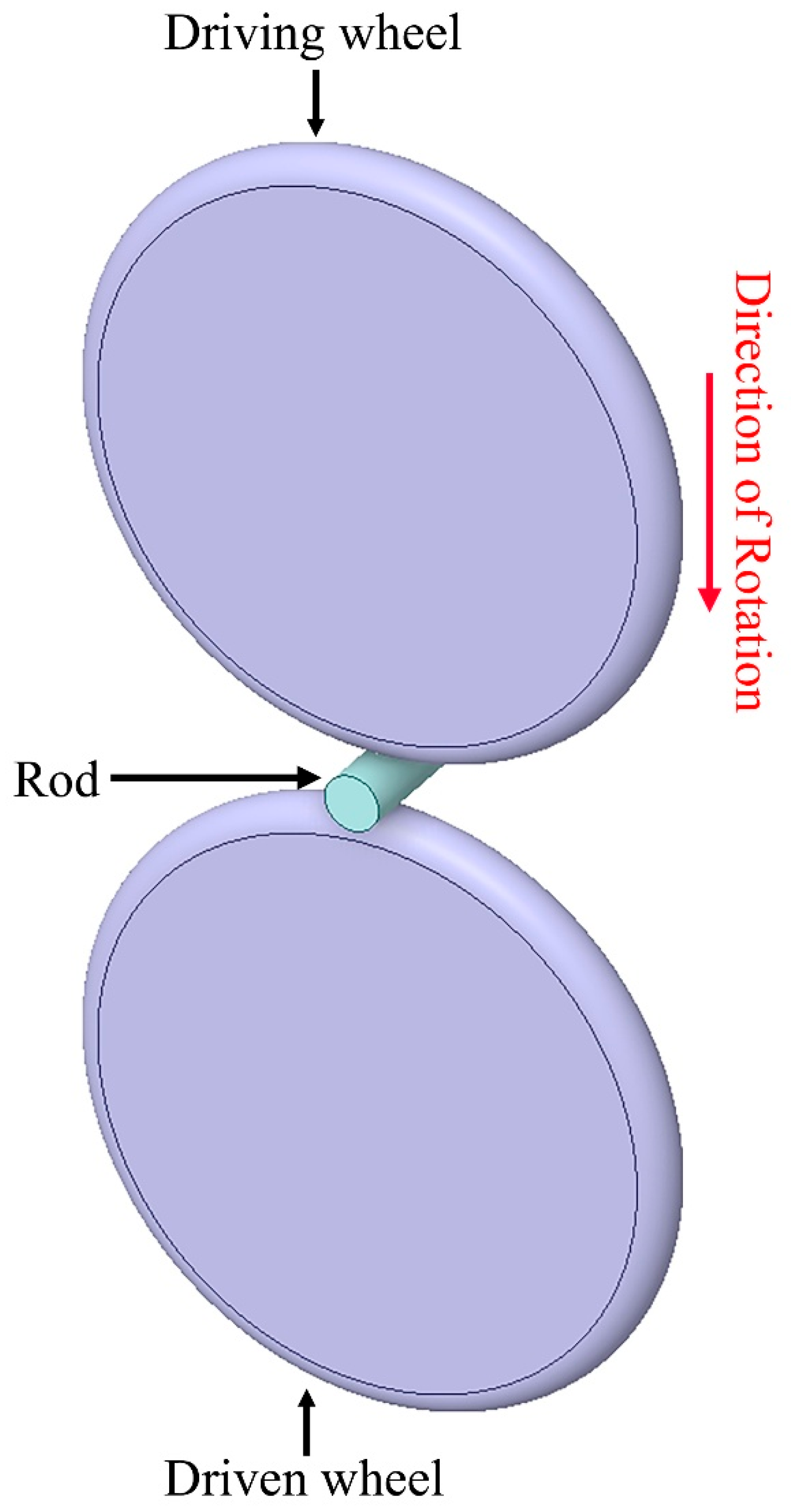
The schematic diagram of the test system is illustrated in Figure 2. The cylindrical specimen has a diameter of 20 mm and a length of 50 mm, while the test wheel has a diameter of 220 mm. The RCF tests were conducted on the specimens under atmospheric conditions until failure. During the testing procedure, the specimen was rotated by the driving wheel, which in turn transmitted motion to the driven wheel. Throughout the experiment, the cylindrical specimen underwent continuous rotation, while a predefined Hertzian contact stress was applied. This experimental methodology for evaluating bearing steel under RCF conditions is widely regarded as reliable. In the present study, accelerated RCF tests were performed with an applied Hertz contact stress of 5.1 GPa [35,36]. The rotational speed was set at 25,000 RPM, with a surface roughness requirement of Ra < 0.05 μm. The induced stress is substantially greater than that experienced in nominally loaded ball bearings (≤2.5 GPa), as conventional RCF testing under nominal load conditions typically requires thousands of hours to achieve meaningful results, rendering it impractical for research applications. The test parameters and corresponding RCF cycles are summarized in Table 4. During the rolling contact fatigue process, lubrication was applied via a jet spray system utilizing 4050 aviation lubricant.

3. Results and Discussion

3.1. Characterization of the Microstructure and Carbides in Carburized CSS-42L Steel

The OM microstructure of the carburized CSS-42L steel is shown in Figure 3a, while Figure 3b,d present the SEM microstructures at different depths from the carburized surface. It can be seen from Figure 3 that a large number of network carbides exist in the surface layer of the carburized CSS-42L steel, and the quantity of these network carbides gradually decreases with increasing depth. Figure 3e–j present the distribution map (EDS mapping) of Cr and Mo elements. The figures clearly illustrate a pronounced enrichment of Cr and Mo within most of the carbides. In addition, among some small spherical carbides, Mo exhibits a more pronounced enrichment, whereas Cr enrichment is relatively insignificant, as indicated by the red arrows in Figure 3. Cr-rich carbides are recognized as M23C6, and the Mo-rich carbides are recognized as M6C according to previous investigation [37]. Taken as a whole, the carbides in carburized CSS-42L steel can be divided into two types, large-sized irregular Cr-rich carbides and small-sized spherical Mo-rich carbides.
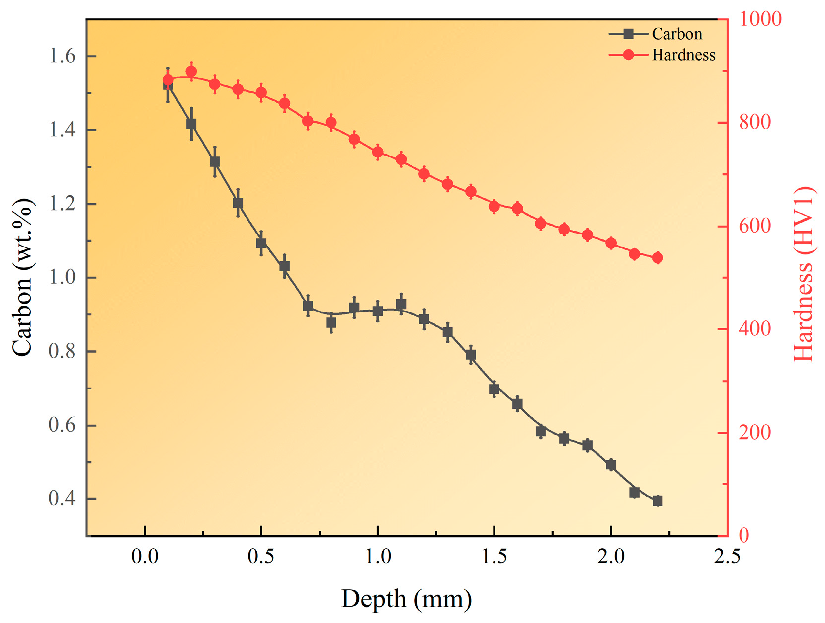
Figure 4 presents the hardness distribution and carbon content at different depths of carburized CSS-42L steel. The maximum hardness at the compact surface reaches 889 HV1. At a depth of 1 mm within the carburized layer, the hardness decreases to 743 HV1 and further declines to 538 HV1 at 2.2 mm. This trend reflects a correlation between hardness reduction and the decrease in carbon concentration during carburization, which aligns with variations in carbide density, type, and size distribution across different depths. Notably, Figure 4 also reveals a significant increase in surface hardness post-carburization, with a marked hardness enhancement in the transition zone and no obvious soft zone. As analyzed in Figure 2 and Figure 3, the enrichment of network carbides imparts a favorable hardening effect to the material through a robust strengthening mechanism.
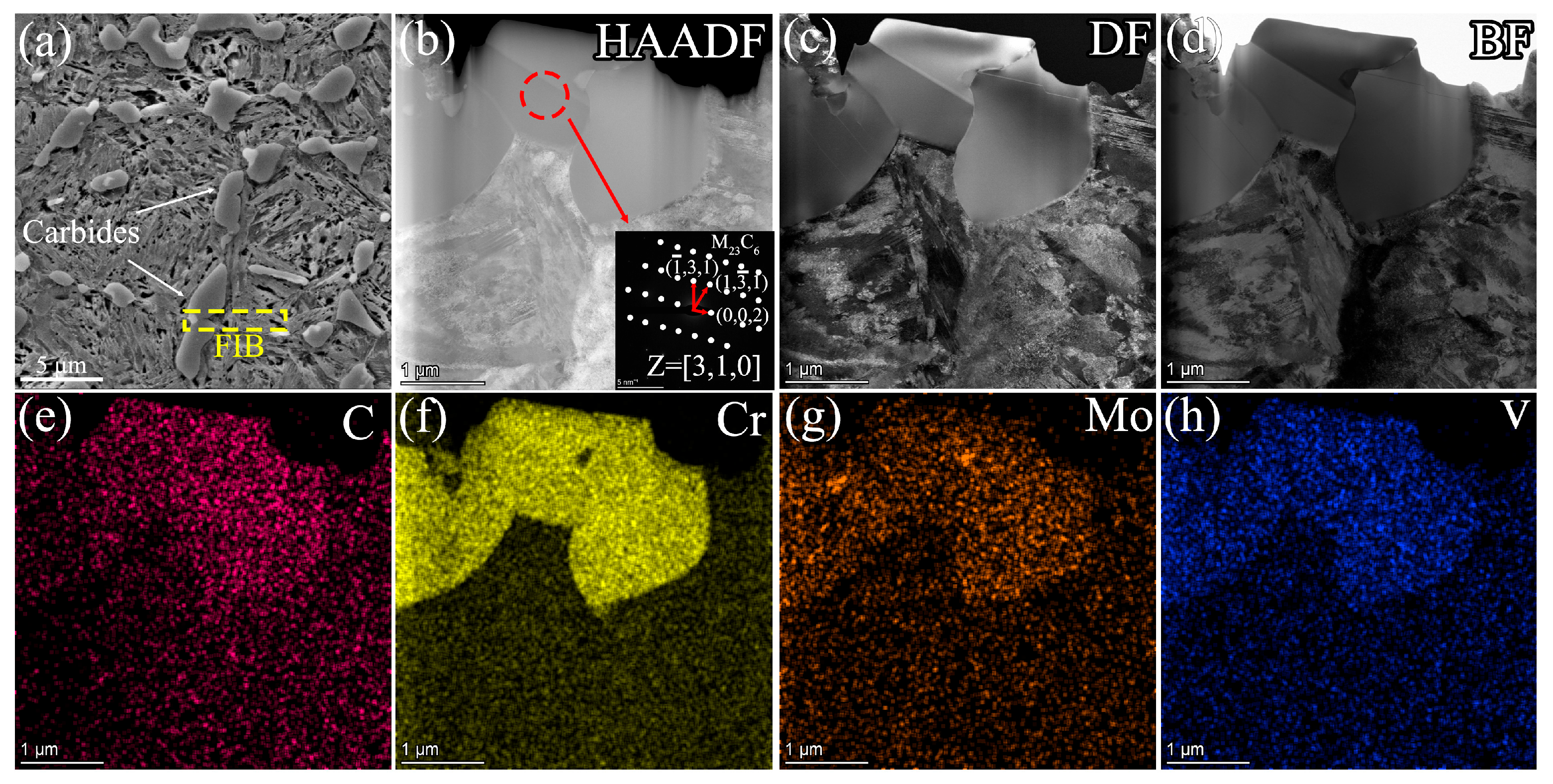
To determine the types of carbides in carburized CSS-42L steel, TEM specimens were prepared from the carburized surface layer via the FIB technique, and then the specimens were subjected to TEM characterization. The results are presented in Figure 5 and Figure 6. Figure 5a shows the sampling position of a large-sized irregular carbide, and the corresponding TEM morphologies are presented in Figure 5b,d). As can be seen in the TEM images, the large-sized irregular carbide formed around the grain boundary. Several carbides interconnected with each other and formed a much larger carbide along the grain boundary. According to the diffraction patterns in Figure 5b, the crystal structure of this carbide is FCC, and its interplanar spacing is close to that of Cr23C6. Figure 5e–h present the EDS mapping results around the carbide. The results indicate that the carbides exhibit significant enrichment of alloying elements such as Cr, Mo, and V. Based on the above comprehensive analysis, it can be concluded that the large-sized network carbides in the carburized layer of CSS-42L steel are mainly M23C6, where M represents alloying atoms such as Fe, Cr, Mo, and V.
Figure 6a illustrates the FIB sampling position of a small-sized carbide in carburized CSS-42L steel. The corresponding TEM results are shown in Figure 6b,c. Figure 6e–h present the distribution of C, Cr, Mo, V elements inside the carbide. The results indicate that the carbide in the figure comprises two components: the upper part of the carbide is Cr-rich M23C6 carbide; the lower part of the carbide is rich in Mo element. The diffraction pattern in Figure 6b indicates that the Mo-rich carbide has FCC crystal structure and the lattice parameter is close to Fe3Mo3C carbide. Thus, the Mo-rich carbide can be determined to be M6C, where “M” denotes Fe, Cr, V and Mo elements.

3.2. Fatigue Failure Mechanism Due to Surface Crack

Figure 7 presents the morphologies of the contact surface before and after the RCF test. Before the RCF test, distinct machining marks are observable on the contact surface, as shown in Figure 7a. After the RCF test, as illustrated in Figure 7b,c, nearly all machining marks disappeared, and the surface morphology appeared much smoother. However, numerous micro-pits are visible on the contact surface in the high-magnification SEM images. The formation of these micro-pits results from the spalling of network carbides. As shown in Figure 7c, surface cracks propagate and interconnect along these network carbides. This indicates that even though the coarse network carbides enhance the hardness of the contact surface, during rolling contact, they act as hard points that collide with the mating component, inducing surface defects and micro-pitting. Meanwhile, stress concentration induced by network carbides during rolling contact significantly increases the probability of surface defect formation. Once such defects and micro-pitting are formed, cracks propagate along the coarser carbide networks, interconnecting and extending further.
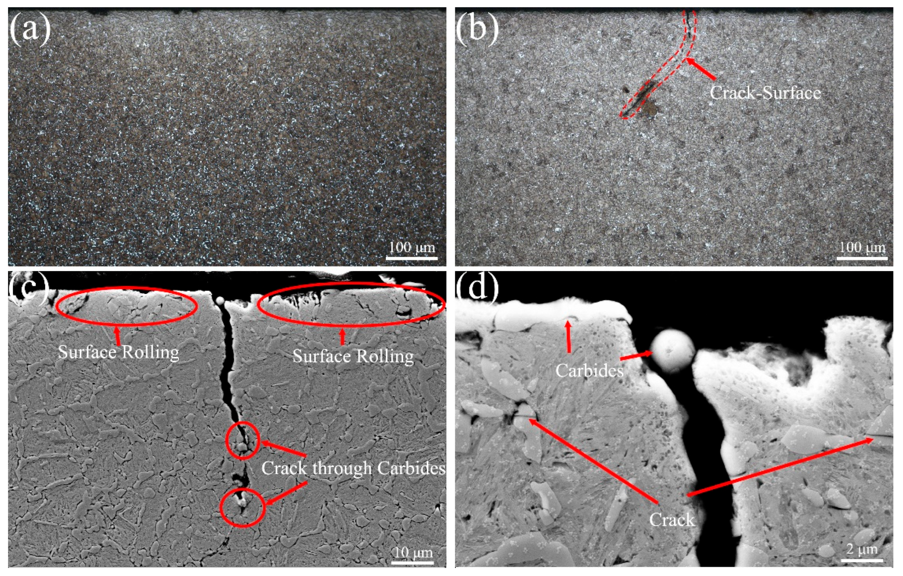
Figure 8 presents the SEM images of the microstructure beneath the raceway after the RCF test. As observed in Figure 8a, no degraded microstructures (such as butterfly structures, light etching regions, or dark etching regions) were detected in the subsurface of the test specimen; however, many fatigue cracks were observed. Figure 8b shows a fatigue crack originating from the contact surface. The fatigue crack first propagates downward perpendicular to the surface and then propagates horizontally under shear stress. Figure 8c,d display magnified SEM images of the microstructure around the crack origin area. As can be seen from the figures, most carbides near the contact surface fractured after cyclic rolling, spalled from the surface, and formed many spalling pits with a depth of several micrometers. The formation of these micro-pits intensifies stress concentration and induces fatigue crack formations at the bottom of the micro-pits. In addition to inducing crack initiation, large-sized network carbides also facilitate the propagation of fatigue cracks. As shown in Figure 8c, large-sized network carbides induce greater stress concentration, thereby facilitating the propagation of cracks along the network carbides.
Figure 9 presents the SEM images of a spalling pit in the specimen after 9.3 × 10⁶ RCF cycles. As observed in Figure 9a, the length of the spalling pit is about 1673 μm and the width is about 957 μm. The width of the spalling pit is larger than the width of the raceway, which may be due to the continuous impact in the late stage of fatigue spalling. As shown in Figure 9b, significant deformation strips are present near the spall pits, cracks are present along the front of the spall pitting, and the fish-scale-like striations are found inside the spall pitting. Figure 9c presents the cross-sectional view of the spalling pits. As observed in the figure, the depth of the spalling pit is about 125 μm. Cracks were not observed at the bottom of the spalling pit. Instead, several fatigue cracks at the front of the spalling pit were detected by SEM. All the fatigue cracks initiated from the contact surface and shifted to propagate parallelly to the contact surface at a certain depth. These cracks may either extend toward the surface or trigger secondary cracks that propagate toward the surface, causing spalling of the surface microstructure. Figure 9d presents the phenomenon whereby secondary cracks propagate to the contact surface and cause spalling. These spalling pits can induce significant stress concentration. Ultimately, directional spalling pit fronts develop at high-stress zones (Region I). Region I exhibits rough morphology due to its prolonged development period. In contrast, Region II displays smoother features because lubricant ingress into cracks generates substantial expansion stress, accelerating crack propagation. Finally, spalling pit formation occurs when subsurface cracks beneath the pit extend, redirect to the surface, and cause suspended material to detach from the matrix (Region III).

3.3. Subsurface-Spalling of Network Carbides in Rolling Contact

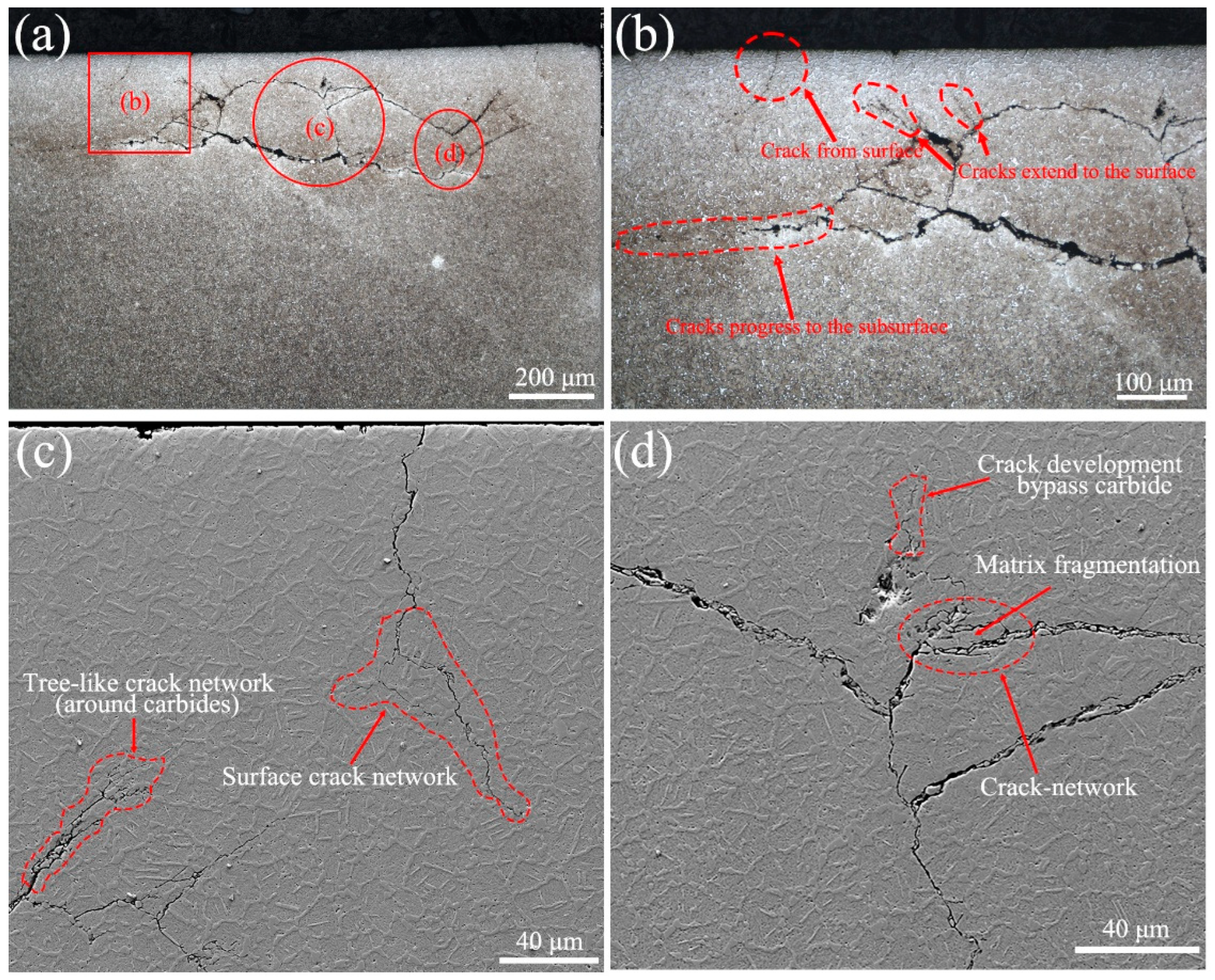
Beyond the fatigue cracks initiated from the contact surface, numerous fatigue cracks were also observed at the subsurface of the specimen after RCF test. Figure 10 illustrates the formation and propagation processes of subsurface cracks. As can be seen in Figure 10a, subsurface cracks lie primarily 100–200 μm beneath the contact surface, and multiple cracks interconnect, forming a crack network. The formation of crack network is closely related to the large-sized network carbides. Figure 10b–d present the magnified images of different parts of the subsurface crack, corresponding to Positions b, c, and d, respectively. It is evident from Figure 10c,d that most subsurface cracks are closely associated with grain boundary carbides. As can be seen from Figure 10b, the fatigue cracks initiated in the subsurface generally propagate in a direction parallel to the contact surface. However, the coarse network carbides promote the initiation and propagation of secondary cracks, resulting in the formation of grid-like cracks in the subsurface. As shown in Figure 10c, the cracks continue to develop along the network carbides, forming a tree-like crack network. Meanwhile, the cracks originating from surface micro-pitting also propagate inward. As can be seen from Figure 10d, due to the formation of the crack mesh, the matrix becomes deformed and fragmented under constant friction and high pressure. This induces significant plastic strain in the martensite adjacent to the cracks; under intense shear, the martensite gradually fragments.
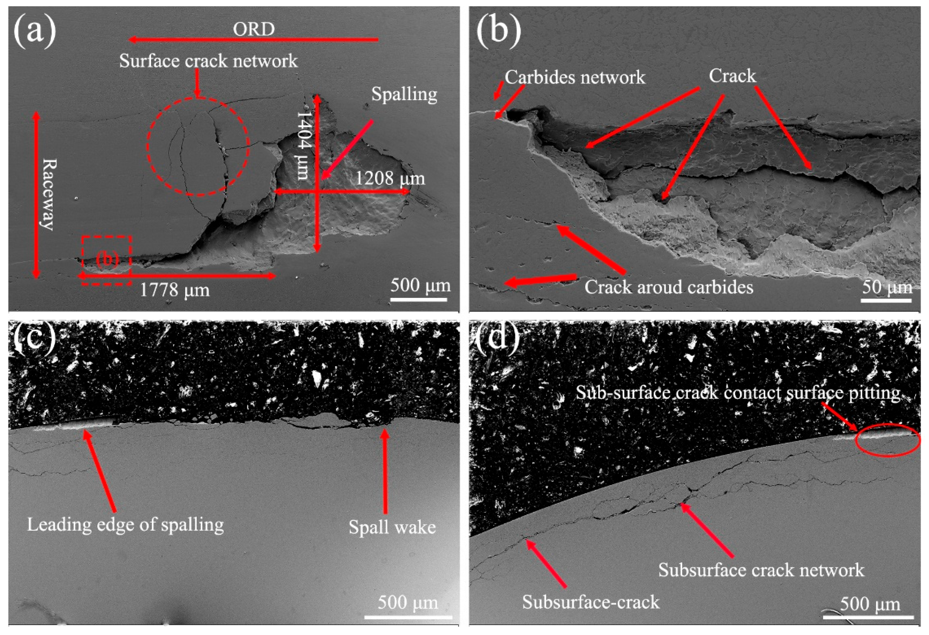
Figure 11 shows the morphology of a spalling pit caused by subsurface cracks. The spalling pit has an irregular shape: its right half is roughly 1404 μm in width and 1208 μm in length, while the left half is not fully spalled. It can be seen from Figure 11a that there exists a crack network at the front of the spalling pit. This proves that the formation of the spalling pit may be related to the crack network in the subsurface. Figure 11b presents the magnified SEM image of the left part of the spalling pit. It can be observed that a coarse carbide network exists at the spalling pit front, and cracks with a fish-scale morphology are present within the leading edge of the spalling pit. It is evident in Figure 11c,d that the subsurface of the spalling pit is connected to long subsurface cracks. The formation of the spalling pit originates from micro-pitting, which is induced by surface network carbides that connect with subsurface cracks.

4. Conclusions

This study focused on revealing the types of carbides in carburized CSS-42L steel and their impacts on the fatigue failure mechanism. The key findings are summarized as follows:
(1)
The carbides in CSS-42L steel after carburizing are mainly M23C6 and M6C. M23C6 carbides are Cr-rich carbides, and they exhibit irregular morphologies and relatively large sizes. The network carbides distributed along the grain boundaries are predominantly M23C6 carbides. M6C carbides are Mo-rich carbides, and they exhibit near-spherical morphologies.
(2)
The spalling of network M23C6 carbides forms micro-spalling pits on the contact surface during RCF, causing local stress concentration and thereby inducing cracks to initiate on the surface. Surface cracks initially propagate perpendicularly to the contact surface and then propagate parallelly to the contact surface under the influence of shear stress.
(3)
Subsurface cracks initiate approximately 100 μm below the surface, with their propagation direction being roughly parallel to the contact surface. Secondary cracks extend along the network carbides, forming a large number of grid-like cracks. Meanwhile, during the development of subsurface cracks may interact with micro-pitting initiating at the surface, which can lead to the expansion of surface micro-pitting.
(4)
During rolling contact fatigue, the size and morphology of networked carbides exacerbate the accumulation of subsurface cyclic shear stress. This stress accumulation subsequently accelerates the initiation and propagation of contact fatigue cracks.

Author Contributions

Conceptualization, M.L., X.L., C.L. and H.L.; methodology, M.L., X.L., C.L. and H.L.; validation, X.L.; investigation, M.L.; resources, M.L. and X.M.; data curation, X.L.; writing —original draft, M.L. and X.L.; writing—review and editing, M.L., X.L., C.L. and X.M.; supervision, C.L., X.M. and H.L.; project administration, H.L.; funding acquisition, H.L. All authors have read and agreed to the published version of the manuscript.

Funding

This research was funded by the National Natural Science Foundation of China (No. 52201053) and the Strategic Priority Research Program of Chinese Academy of Sciences (No. XDA0390104).

Data Availability Statement

The original contributions presented in this study are included in the article. Further inquiries can be directed to the corresponding author.

Conflicts of Interest

Author Ming Liu was employed by the company AECC Harbin Bearing Co., Ltd. The remaining authors declare that the research was conducted in the absence of any commercial or financial relationships that could be construed as a potential conflicts of interest.

References

  1. Braza, J.F.; Pearson, P.K. Tribological and metallurgical evaluation of ferritic nitrocarburized M-50 and M-50 NiL steels. Creat. Use Bear. Steels 1993, 1195, 49. [Google Scholar]
  2. Braza, J.F.; Pearson, P.K.; Hannigan, C.J. The Performance of 52100, M-50, and M-50 NiL Steels in Radial Bearings. In International Off-Highway & Powerplant Congress & Exposition; SAE Transactions: Warrendale, PA, USA, 1993; pp. 437–449. [Google Scholar]
  3. Yu, X.F.; Zheng, D.Y.; Yang, X.F.; Wang, S.Y.; An, M.; Yan, G.B.; Xia, Y.Z.; Xing, F. Effect of carbide precipitation behavior at high temperatures on microstructure and mechanical properties of M50 steel. J. Mater. Res. Technol. 2022, 18, 1155–1165. [Google Scholar] [CrossRef]
  4. Zhang, Z.; Wang, F.; Yin, F.; Qian, D.; Liu, X.; Wu, M. Microstructure evolution and deformation behaviors of pulse electro-assisted deformation in M50 bearing steel. J. Mater. Res. Technol. 2023, 23, 4909–4921. [Google Scholar] [CrossRef]
  5. Wei, P.; Bai, P.; Yue, L.; Zhou, X.; Wen, X.; Zhao, H.; Meng, Y.; Tian, Y. Comparing friction behavior and mechanism of three generation bearing steel (GCr15, M50, CSS-42L) paired silicon nitride under ester oil lubrication from room temperature to 350 °C. J. Mater. Res. Technol. 2024, 30, 1354–1367. [Google Scholar] [CrossRef]
  6. Yang, Y.; Zhang, C.; Wang, Y.; Dai, Y.; Luo, J. Friction and wear performance of titanium alloy against tungsten carbide lubricated with phosphate ester. Tribol. Int. 2016, 95, 27–34. [Google Scholar] [CrossRef]
  7. Mukhopadhyay, P.; Kannaki, P.S.; Srinivas, M.; Roy, M. Microstructural developments during abrasion of M50 bearing steel. Wear 2014, 315, 31–37. [Google Scholar] [CrossRef]
  8. Guetard, G.; Toda-Caraballo, I.; Rivera-Díaz-del-Castillo, P.E.J. Damage evolution around primary carbides under rolling contact fatigue in VIM–VAR M50. Int. J. Fatigue 2016, 91 Pt 1, 59–67. [Google Scholar] [CrossRef]
  9. Li, Y.J.; Herbig, M.; Goto, S.; Raabe, D. Atomic scale characterization of white etching area and its adjacent matrix in a martensitic 100Cr6 bearing steel. Mater. Charact. 2017, 123, 349–353. [Google Scholar] [CrossRef]
  10. Arakere, N.K.; Branch, N.; Levesque, G.; Svendsen, V.; Forster, N.H. Rolling Contact Fatigue Life and Spall Propagation of AISI M50, M50NiL, and AISI 52100, Part II: Stress Modeling. Tribol. Trans. 2009, 53, 42–51. [Google Scholar] [CrossRef]
  11. Oezel, M.; Schwedt, A.; Janitzky, T.; Kelley, R.; Bouchet-Marquis, C. Formation of white etching areas in SAE 52100 bearing steel under rolling contact fatigue—Influence of diffusible hydrogen. Wear 2018, 414–415, 352–365. [Google Scholar] [CrossRef]
  12. Liu, X.; Guo, Z.; Lu, Z.; Qin, L. Tribological behavior of the wear-resistant and self-lubrication integrated interface structure with ordered micro-pits. Surf. Coat. Technol. 2023, 454, 129159. [Google Scholar] [CrossRef]
  13. Liu, X.; Wang, Y.; Qin, L.; Guo, Z.; Lu, Z.; Zhao, X.; Dong, H.; Xiao, Q. Friction and wear properties of a novel interface of ordered microporous Ni-based coating combined with MoS2 under complex working conditions. Tribol. Int. 2023, 189, 108970. [Google Scholar] [CrossRef]
  14. Tomasello, C.M.; Burrrier, H.I.; Knepper, R.A.; Balliett, S.; Maloney, J.L. Progress in the Evaluation of CSS-42L™: A High Performance Bearing Alloy. In Bearing Steel Technology; ASTM International: West Conshohocken, PA, USA, 2002; pp. 375–385. [Google Scholar]
  15. Burrier, H.I.; Tomasello, C.M.; Balliett, S.A.; Maloney, J.L.; Milam, D.L.; Ogden, W.P. Development of CSS-421™, A High Performance Carburizing Stainless Steel for High Temperature Aerospace Applications. In Bearing Steels: Into the 21st Century; ASTM International: West Conshohocken, PA, USA, 1998; pp. 374–390. [Google Scholar]
  16. Li, S.; Xiao, M.; Ye, G.; Zhao, K.; Yang, M. Effects of deep cryogenic treatment on microstructural evolution and alloy phases precipitation of a new low carbon martensitic stainless bearing steel during aging. Mater. Sci. Eng. A 2018, 732, 167–177. [Google Scholar] [CrossRef]
  17. Hetzner, D.W.; Van Geertruyden, W. Crystallography and metallography of carbides in high alloy steels. Mater. Charact. 2008, 59, 825–841. [Google Scholar] [CrossRef]
  18. Chen, X.; Zheng, L.; Feng, S.; Li, J.; Wang, F.; Zhang, H. Tempering influence on microstructural evolution and mechanical properties in a core of CSS-42L bearing steel. Mater. Sci. Eng. A 2022, 861, 144233. [Google Scholar] [CrossRef]
  19. Tai, S.; Bu, C.; Wang, Y.; Yue, T.; Liu, H.; Wang, L. Identification of aircraft longitudinal aerodynamic parameters using an online corrective test for wind tunnel virtual flight. Chin. J. Aeronaut. 2024, 37, 261–275. [Google Scholar] [CrossRef]
  20. Li, T.; Shi, H.; Bai, X.; Li, N.; Zhang, K. Rolling bearing performance assessment with degradation twin modeling considering interdependent fault evolution. Mech. Syst. Signal Process. 2025, 224, 112194. [Google Scholar] [CrossRef]
  21. Shi, J.; Zhao, B.; He, J.; Lu, X. The optimization design for the journal-thrust couple bearing surface texture based on particle swarm algorithm. Tribol. Int. 2024, 198, 109874. [Google Scholar] [CrossRef]
  22. Sadeghi, F.; Jalalahmadi, B.; Slack, T.S.; Raje, N.; Arakere, N.K. A Review of Rolling Contact Fatigue. J. Tribol. 2009, 131, 041403. [Google Scholar] [CrossRef]
  23. Voskamp, A.P. Material Response to Rolling Contact Loading. J. Tribol. 1985, 107, 359–366. [Google Scholar] [CrossRef]
  24. Warhadpande, A.; Sadeghi, F.; Evans, R.D. Microstructural Alterations in Bearing Steels under Rolling Contact Fatigue Part 1—Historical Overview. Tribol. Trans. 2013, 56, 349–358. [Google Scholar] [CrossRef]
  25. Maharjan, N.; Zhou, W.; Zhou, Y. Microstructural study of bearing material failure due to rolling contact fatigue in wind turbine gearbox. In Proceedings of the International Symposium on Current Research in Hydraulic Turbines, Dhulikhel, Nepal, 14 March 2016. [Google Scholar]
  26. Mitamura, N.; Hidaka, H.; Takaki, S. Microstructural Development in Bearing Steel during Rolling Contact Fatigue. Mater. Sci. Forum 2007, 539–543, 4255–4260. [Google Scholar] [CrossRef]
  27. Cai, X.; Hu, X.; Lu, X.; Liu, H.; Cao, Y.; Li, D. Exploring the ultrahigh rolling contact fatigue life of M50 bearing steel by adjusting the cryogenic sequence. J. Mater. Sci. Technol. 2024, 169, 243–250. [Google Scholar] [CrossRef]
  28. Olver, A.V. The Mechanism of Rolling Contact Fatigue: An Update. Proceedings of the Institution of Mechanical Engineers. Part J J. Eng. Tribol. 2005, 219, 313–330. [Google Scholar] [CrossRef]
  29. Grabulov, A.; Ziese, U.; Zandbergen, H.W. TEM/SEM investigation of microstructural changes within the white etching area under rolling contact fatigue and 3-D crack reconstruction by focused ion beam. Scr. Mater. 2007, 57, 635–638. [Google Scholar] [CrossRef]
  30. Evans, M.H.; Richardson, A.D.; Wang, L.; Wood, R.; Anderson, W.B. Confirming subsurface initiation at non-metallic inclusions as one mechanism for white etching crack (WEC) formation. Tribol. Int. 2014, 75, 87–97. [Google Scholar] [CrossRef]
  31. Morsdorf, L.; Mayweg, D.; Li, Y.; Diederichs, A.; Raabe, D.; Herbig, M. Moving cracks form white etching areas during rolling contact fatigue in bearings. Mater. Sci. Eng. A 2020, 771, 138659. [Google Scholar] [CrossRef]
  32. Kang, J.H.; Hosseinkhani, B.; Williams, C.A.; Moody, M.P.; Bagot, P.A.J.; Rivera-Díaz-del-Castillo, P.E.J. Solute redistribution in the nanocrystalline structure formed in bearing steels. Scr. Mater. 2013, 69, 630–633. [Google Scholar] [CrossRef]
  33. Zheng, C.; Dan, R.; Zhang, F.; Lv, B.; Yan, Z.; Shan, J.; Long, X. Effects of retained austenite and hydrogen on the rolling contact fatigue behaviours of carbide-free bainitic steel. Mater. Sci. Eng. A 2014, 594, 364–371. [Google Scholar] [CrossRef]
  34. Liang, X.Z.; Rivera-Díaz-del-Castillo, P.E.J. Hydrogen-accelerated white etching area formation in bearings under rolling contact fatigue. Int. J. Fatigue 2022, 159, 106753. [Google Scholar] [CrossRef]
  35. Grabulov, A. Fundamentals of Rolling Contact Fatigue. Ph.D. Thesis, Delft University of Technology, Delft, The Netherlands, 2010. [Google Scholar]
  36. Bhadeshia, H.K.D.H. Steels for bearings. Prog. Mater. Sci. 2012, 57, 268–435. [Google Scholar] [CrossRef]
  37. Pian, L.P.; Li, H.H.; Pang, X.D.; Sun, Y.; Chi, H.X.; Gu, J.B. Mechanical behavior and microstructural evolution of a modified CSS-42L steel during tempering. J. Iron Steel Res. Int. 2025. [Google Scholar] [CrossRef]
Figure 1. Schematic of carbide statistics and inclusion mapping: (a) SEM image of near-surface carbides, (b) extracted carbide morphology after image processing, and (c) inclusion mapping and corresponding EDS spectrum.
Metals 15 01013 g001
Figure 2. Schematic diagram of the RCF test.
Metals 15 01013 g002
Figure 3. The microstructure and carbides of carburized CSS-42LSteel. (Yellow Lines—M23C6, Red Lines—M6C). (a) OM-stitched panorama micrograph of the carburized layer, (bd) SEM images of the carbides at different depths from the surface, (eg) EDS mapping of Cr element, and (hj) EDS mapping of Mo element.
Metals 15 01013 g003
Figure 4. Carbon content and hardness at different depths from the surface.
Metals 15 01013 g004
Figure 5. TEM images of a large-sized networked carbide: (a) FIB sampling position for TEM specimen, (b) high-angle annular dark-field image (HAADF) of the carbide, (c) dark-field (DF) TEM image of carbides, (d) bright-field (BF) TEM image of carbides, and (eh) EDS mapping.
Metals 15 01013 g005
Figure 6. TEM images of a small-sized carbide: (a) FIB sampling position for TEM specimen, (b) high-angle annular dark-field image (HAADF) of the carbide, (c) dark-field (DF) TEM image of carbides, (d) bright-field (BF) TEM image of carbides, and (eh) EDS mapping.
Metals 15 01013 g006
Figure 7. The morphologies of the contact surface before and after RCF test: (a) before RCF test and (b,c) after RCF test.
Metals 15 01013 g007
Figure 8. The microstructure after RCF test and the fatigue crack originating from the contact surface: (a) OM image of the microstructure after RCF test, (b) OM image of the fatigue crack originating from contact surface, and (c,d) magnified SEM images of the microstructure around the crack initiation region.
Metals 15 01013 g008
Figure 9. The morphology of the spalling pit due to surface crack: (a) overall view of the spalling pit, (b) the magnified image of the spalling pit, (c) the cross-sectional view of the spalling pit, and (d) the magnified image of fatigue cracks and micro-pits.
Metals 15 01013 g009
Figure 10. OM and SEM images of microstructure beneath the raceway after 2.0 × 10⁸ cycles: (a) overall, (b) surface crack at position (b) in Figure 10a, (c) enlarged view of the subsurface crack at position (c) in Figure 10a, and (d) enlarged view of the subsurface crack at position (d) in Figure 10a.
Metals 15 01013 g010
Figure 11. SEM images of spall pits at 2.0 × 10⁸ cycles: (a) overall; (b) leading edge spall pits; (c) side profile topography of spall pits; (d) subsurface crack network below spall pits.
Metals 15 01013 g011
Table 1. Chemical composition of CSS-42L bearing steel (wt.%).
ElementCSiMnCrMoCoVNiNb
Content0.130.180.0913.804.7012.700.602.000.02
Table 2. Inclusion scanning area and statistics.
Swept Area (μm2)CountAverage Diameter (μm)Maximum Diameter (μm)Percentage of Area
30.00401.542.760.00001
Table 3. Size distribution of inclusions.
Number Density1–2 µm2–5 µm5–10 µm>10 µm
1.3333
82.50%
7
17.50%
0
0%
0
0%
Table 4. Test numbers and corresponding RCF cycles of CSS-42L steel.
Test NumberRCF Loading Cycles
19.3 × 10⁶
21.2 × 10⁷
32.6 × 10⁷
43.6 × 10⁷
52.0 × 10⁸
Disclaimer/Publisher’s Note: The statements, opinions and data contained in all publications are solely those of the individual author(s) and contributor(s) and not of MDPI and/or the editor(s). MDPI and/or the editor(s) disclaim responsibility for any injury to people or property resulting from any ideas, methods, instructions or products referred to in the content.