Article

Investigation of the Effects of Gas Metal Arc Welding and Friction Stir Welding Hybrid Process on AA6082-T6 and AA5083-H111 Aluminum Alloys

1
School of Engineering, University of Cádiz, Avda. Universidad de Cádiz, 10, 11510 Puerto Real, Spain
2
LORTEK, Basque Research and Technology Alliance (BRTA), Arranomendia kalea 4A, 20240 Ordizia, Spain
*
Author to whom correspondence should be addressed.
Metals 2025, 15(9), 1005; https://doi.org/10.3390/met15091005
Submission received: 18 July 2025 / Revised: 3 September 2025 / Accepted: 7 September 2025 / Published: 9 September 2025
(This article belongs to the Section Welding and Joining)

Abstract

Friction stir welding (FSW) has emerged as a solid-state joining technique offering notable advantages over traditional welding methods. Gas metal arc welding (GMAW), a fusion-based process, remains widely used due to its high efficiency, productivity, weld quality, and ease of automation. To combine the benefits of both techniques, a hybrid welding approach integrating GMAW and FSW has been developed. This study investigates the impact of this hybrid technique on the joint quality and properties of AA5083-H111 and AA6082-T6 aluminum alloys. Butt joints were produced on 6 mm thick plates, with variations in friction process parameters. Characterization included macro- and microstructural analyses, mechanical testing (hardness and tensile strength), and corrosion resistance evaluation through stress corrosion cracking tests. Results showed that FSW significantly refined and homogenized the microstructure in both alloys. AA5083-H111 welds achieved a joint efficiency of 99%, while AA6082-T6 reached 66.7%, differences attributed to their distinct strengthening mechanisms and the thermal–mechanical effects of FSW. To assess hydrogen-related behavior, slow strain rate tensile (SSRT) tests were conducted in both inert and hydrogen-rich environments. Hydrogen content was measured in arc, friction, and overlap zones, revealing variations depending on the alloy and microstructure. Despite these differences, both alloys exhibited negligible hydrogen embrittlement. In conclusion, the GMAW–FSW hybrid process successfully produced sound joints with good mechanical and corrosion resistance performance in both aluminum alloys. The findings demonstrate the potential of hybrid welding as a viable method for enhancing weld quality and performance in applications involving dissimilar aluminum alloys.

1. Introduction

Welding plays a crucial role in modern industrial fabrication and is one of the most widely utilized manufacturing techniques. Arc welding processes are a group of fusion-based technologies that rely on the establishment of an electric arc between an electrode and the base metal as the heat source for joining metallic materials. Among them, the gas metal arc welding (GMAW) is one of the most frequently used processes due to its advantages in industrial applications. It involves the use of a consumable electrode in wire form fed continuously into the weld pool and shielding gas to protect the weld bead from oxidation. One of its key benefits is its high efficiency and productivity. It also allows for automation, making it suitable for robotic welding applications. In addition, the process is versatile, capable of welding a wide range of metallic alloys, including steels, stainless steels, and aluminum alloys [1,2].
Despite its advantages, the weldability of aluminum alloys must be carefully considered for GMAW application. Susceptibility to hot cracking and hydrogen-induced porosity are critical issues affecting the mechanical performance of GMAW welds [3,4]. Aluminum-magnesium-silicon alloys (6000 series) are particularly susceptible to hot cracking and internal porosity when welded using GMAW, presenting challenges in optimizing welding parameters and process conditions. Precise control of arc process parameters is essential to ensure high-quality welds while minimizing defects. In contrast, 5000 series aluminum alloys present additional challenges, as several critical issues must be addressed, including hot cracking, porosity from hydrogen absorption, distortion, and oxide formation [5,6,7]. Another major concern is sensitization and strength degradation, as these alloys are susceptible to stress corrosion cracking (SCC) when exposed to temperature.
In recent decades, innovative welding techniques have been developed to address the challenges associated with conventional fusion-based processes [8]. Among them, friction stir welding (FSW) has emerged as a solid-state joining method, offering significant advantages over traditional welding techniques. Developed in 1991 by The Welding Institute (TWI) [9,10], the process employs a non-consumable rotating tool, which is plunged into the workpieces and moved transversely along the weld seam, generating frictional heat to soften and stir the materials. The tool, consisting of a pin and shoulder, facilitates plastic deformation and promotes a strong metallurgical bond without melting the material [11,12]. As a solid-state process, welding occurs below the melting point and eliminates common fusion-welding defects such as porosity, hot cracking, and solidification shrinkage, making it particularly suitable for materials like aluminum, magnesium, and copper alloys [13,14]. However, one of the limitations of FSW is the requirement for high downward force and rigid clamping, necessitating specialized equipment to prevent material movement during welding. This increases setup complexity and makes FSW less adaptable for manual or on-site applications.
Recently, a hybrid welding technique combining arc welding and FSW has been developed to leverage the advantages of both processes while minimizing their drawbacks [15]. In this method, the arc process is first applied to one side of the workpieces as a root welding process, followed by FSW on the opposite side (Figure 1). As a result, both welding processes contribute to joining different sections of the material’s thickness. To ensure complete material processing, there is an overlapping region in the middle, where FSW is performed on the arc-welded section. This overlap enhances joint integrity, mechanical properties, and defect mitigation, making the hybrid technique a promising solution for high-performance welding applications.
In terms of benefits, arc welding is performed at higher processing speeds, ensuring efficient fusion, whereas friction stir welding operates at lower speeds, promoting a more homogeneous mixing of the materials. This combination can result in a higher-quality weld with fewer defects and improved mechanical properties. The friction technique also helps by minimizing the presence of gases during the welding process, which significantly reduces the risk of porosity in the welded joint, compensating for potential porosity that could arise from the complete fusion generated by the arc.
Only a few studies have been developed to investigate this technique and the properties of the hybrid joint. Lim et al. [15] investigated the mechanical properties of high-strength pipe steels (API 5L X70 grade) with 15.8 mm wall thickness welded using this hybrid technique with orbital FSW. The results indicated that the overall mechanical properties were comparable to the base metal; however, a small soft zone was noted in the welding zone. Also using pipeline steel, Mahoney et al. [16] studied the hybrid process applied to API 5L X42 grade pipes with a 12 mm wall thickness. The hardness measurements revealed that the root arc weld was the hardest location in the weld zone (150–180 HV), whereas the friction zone displayed softer values (125–140 HV). The study conducted by El-Fahhar et al. [17] focused on an aluminum alloy, specifically AA6082-T6, with a thickness of 5 mm. In this study, the Friction Stir Processing (FSP), a variant of the FSW in which a pinless tool was applied to treat the surface of the MIG-welded joint, was used. The results indicated that the hybrid welds had improved hardness and strength compared to the as-welded MIG joint. Another investigation on aluminum alloys, Rao et al. [18] studied the AA2219-T6 using a variation of the hybrid welding process. In this approach, the Gas Tungsten Arc Welding (GTAW) process was first applied to one side of the workpiece, followed by the friction welding process. The results demonstrated that the friction process effectively addressed many of the typical drawbacks of fusion welding. Notably, it facilitated the complete elimination of the weld’s solidification structure and improved the corrosion properties by removing copper-depleted regions in the weld microstructure, thereby enhancing weld corrosion resistance.
Despite the promising results demonstrated in previous studies, a comprehensive assessment of the full potential of this hybrid welding technique remains limited. In particular, the evaluation of stress corrosion cracking (SCC) and hydrogen-assisted damage in aluminum joints is essential for ensuring structural integrity, especially in industries such as aerospace, automotive, and marine engineering. Aluminum alloys, particularly the 5000 and 6000 series, are known to be susceptible to hydrogen absorption and embrittlement under specific environmental and loading conditions [19,20]. Understanding how the hybrid welding process influences hydrogen uptake and its effects on joint integrity is therefore critical. In this context, this study aims to analyze the effects of hybrid welding using GMAW and FSW on AA5083-H111 and AA6082-T6, focusing on metallurgical characteristics (macro and microstructural analyses), mechanical properties (hardness and tensile strength), and corrosion resistance (stress corrosion cracking).

2. Materials and Methods

2.1. Materials

Aluminum alloys AA5083-H111 and AA6082-T6 plates with a thickness of 6 mm were used as base materials for this study. For the GMAW process, ER4043 filler metal was used for arc welding of AA6082-T6, while ER5183 filler metal was selected for the AA5083-H111 alloy. In both cases, a diameter of 1.2 mm was employed. The chemical compositions and mechanical properties of the materials (i.e., base materials and filler metals) used in this work are provided in Table 1 and Table 2, respectively.

2.2. Welding Processes

The hybrid joints were produced in two phases: first, arc welding was applied to create a “root” pass, followed by the friction welding on the opposite side of the arc weld.
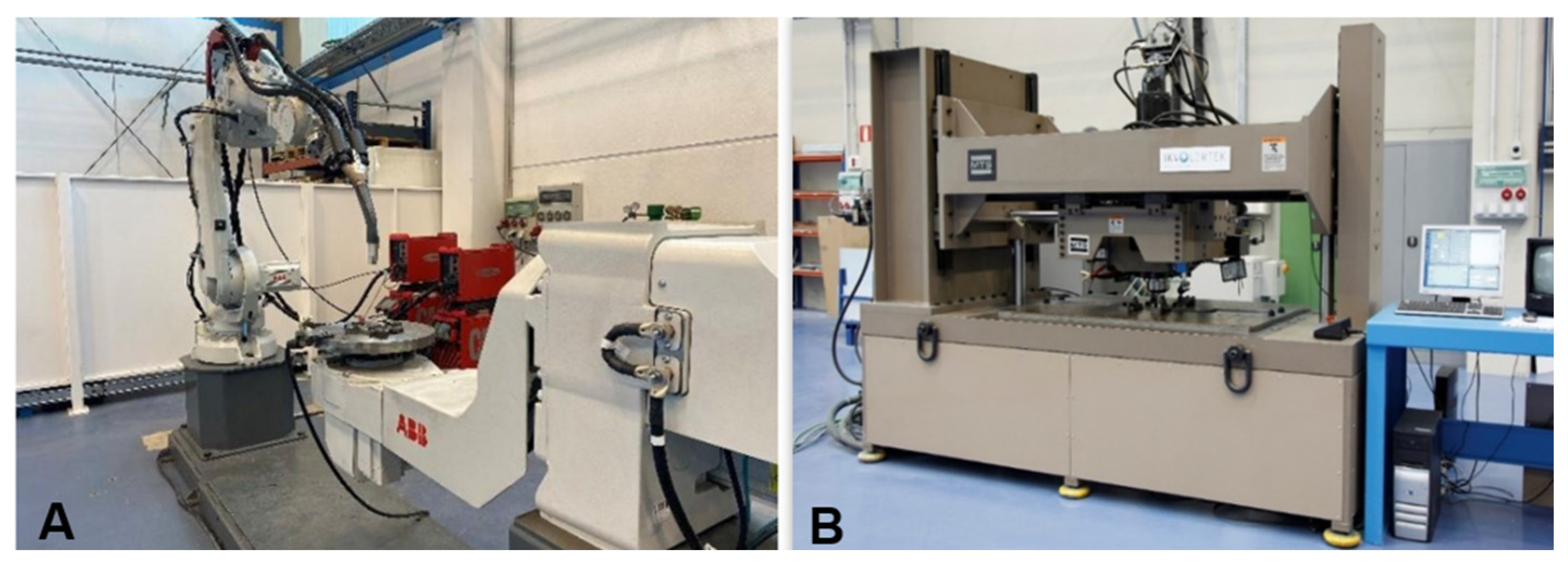
The GMAW process was carried out in a robotic welding cell equipped with an ABB IRB 4600–45/2.05 industrial robot (ABB: ASEA Brown Bovery, S.A., Bilbao, Spain), a FRONIUS TPS400i MIG-MAG power source (FRONIUS España S.L.U., Bilbao, Spain), and an ABB positioner (ABB: ASEA BROWN BOVERY, S.A., Bilbao, Spain) (Figure 2A). Regarding the joint geometry, a standard V-butt joint configuration, with a root face of 3 mm and a bevel angle of 60° was selected. The “V”-shaped groove design improves filler metal flow and distribution through the joint. Before GMAW welding, different pre-processing steps were performed to minimize weldability issues related to the quality and chemistry of the base material surface. For example, acetone was applied for cleaning, and brushing was carried out to reduce alumina on the surface. Additional measures were also considered to reduce hydrogen absorption by the materials. The main process conditions were also defined: pure argon was selected as the shielding gas; an increased gas flow rate was used to enhance protection of the molten metal; a reduced contact-tip-to-workpiece distance (CTWD) was adopted to improve shielding effectiveness; and the orientation of the welding torch was optimized to minimize porosity in the welds. An initial parametrization stage of the GMAW process was conducted to identify the welding conditions and parameters that minimize the occurrence of welding defects. The optimized GMAW process conditions were Pulse MultiControl process (i.e., PMC), welding current of 140 A, voltage of 19.4 V, and welding speed of 8 mm/s for both alloys.
After the arc welding process, FSW was applied to the opposite side of the samples using the MTS I-STIR PDS (Eden Prairie, MN, USA) equipment. Before FSW, the plates were cleaned with isopropyl alcohol to remove any dirt, rust, or grease. The friction joints were performed in a friction welding equipment (Figure 2B) with a 0.5 × 1.0 m2 working area, 100 kN axial force, and 3000 rpm rotation speed. To investigate the effect of the heat input developed by the FSW process, two different welding conditions were applied to each aluminum alloy, as detailed in Table 3, using the formula presented in [21], where the torque corresponded to the mean value obtained during the welding phase.
The joints were produced using a non-consumable steel tool with a 13.45 mm shoulder diameter, featuring a scroll design and a cylindrical threaded pin with triple facets, measuring 5.8 mm in diameter and 4.6 mm in length. The process was conducted with a controlled tool depth and a tilt angle of 1.5°, ensuring optimal weld quality and process stability.

2.3. Joint Analysis

Cross-section samples were obtained perpendicular to the hybrid welding direction to examine the joint characteristics. The samples underwent standard metallographic procedures, including grinding and polishing. Macro and microstructural analyses of the joints were performed by optical microscopy (OM). Basic metallography procedures were adopted, and the samples were then etched with a Keller nº 2 reagent. The dimensions of the welding regions were measured using Leica software (Leica Application Suite, Version 4.13.0—Build: 310). Microhardness tests were performed using a Vickers microhardness tester (Durascan 20, EMCO-TEST Prüfmaschinen GmbH), equipped with Ecos Workflow software (version V.2.10.0, 2007–2013), applying a load of 500 gf (HV0.5) within 15 s. For each analysis zone, three indentations were made, evenly spaced, at a distance of 0.7 mm, to avoid interaction, and placed in representative microstructural areas. Tensile strength testing was carried out to evaluate the mechanical behavior of the joints. Three samples were used for each welding condition to determine the mechanical properties, and average values were reported. The 25 mm wide specimens were subjected to tensile testing at a rate of 0.1 mm/s, using a Zwick Roell Z100 mechanical testing machine. For the corrosion resistance evaluations, Slow Strain Rate Testing (SSRT) was only on the P1 welding conditions in a hydrogen environment (according to standard ASTM G129 [22] or ISO 16573-2 [23]) at a head displacement rate of 0.002 mm/s, as specified by the ASTM G142 [24]. Additionally, SSRT tests were performed under an inert nitrogen (N2) atmosphere to serve as reference conditions, enabling a comparative assessment of the mechanical behavior and hydrogen embrittlement susceptibility in hydrogen-charged environments. Once the specimen was mounted, for tests under hydrogen pressure, the autoclave was pressurized to 280 bar pressure and maintained for 48 h for hydrogen pre-charged specimens.
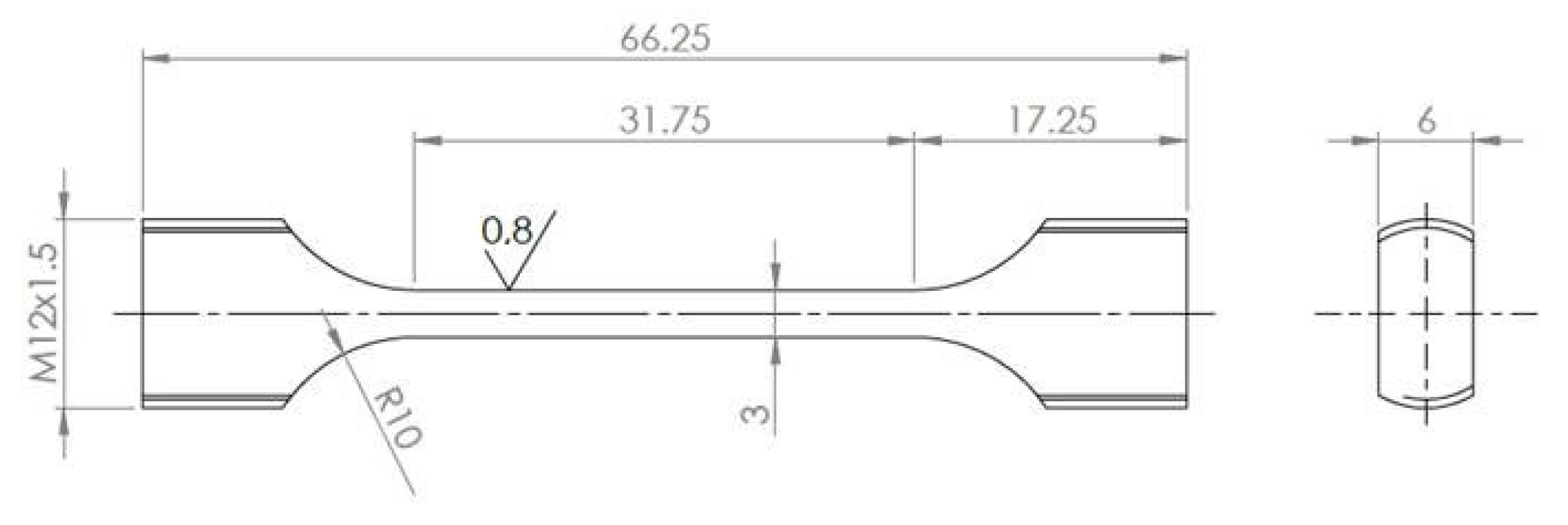
Due to the need to study the full welding thickness in each plate, it was necessary to define custom tensile specimens. In Figure 3, flat specimens were designed with modified grip heads, tailored according to the thickness of the plate and the geometric limitations of the testing equipment. The specimens were machined in a direction perpendicular to the weld bead. Specifically, a thickness value (e) of 3 mm was chosen.
After the test, the elongation, yield strength, ultimate tensile strength, and area reduction were determined. For specimens tested in a hydrogen environment, the embrittlement index was calculated by comparing parameters to those obtained from specimens tested in an inert atmosphere. The hydrogen embrittlement index was determined for the parameters analyzed, based on established methodologies described in relevant literature and standards. One of the indexes considered was that defined in ASTM G142, specifically the hydrogen environment embrittlement (HEE), as defined by the Canadian Standards Association (CSA) [25] and NASA (NASA/TM—2016–218602 Hydrogen Embrittlement [26]), was applied. This index was calculated as HEE = H2/Air and ranges from 0 to 1, allowing the classification of materials into five embrittlement severity categories with the corresponding NTS ratio, from Negligible (1.0–0.97) to Extreme (0.49–0.0). In this study, the HEE index was employed to classify the behavior of the analyzed aluminum alloys in hydrogen environments, regardless of the differences in specimen geometry compared with those prescribed in the standard.
Hydrogen content in the joint samples was measured using a LECO H836EN analyzer (LECO Corporation, St. Joseph, MI, USA), which operates based on the inert gas fusion method with thermal conductivity detection. The procedure included equipment calibration (blank measurements, controlled H2 dosing, and the use of certified reference standards), ultrasonic cleaning of the specimens in acetone, and hydrogen pre-charging at 280 bar for 48 h. Subsequently, the samples extracted from the friction, arc, and overlap zones of the joints made with AA5083-H111 and AA6082-T6 were weighed using a precision balance with 0.0001 g resolution and analyzed with a current pulse of 650 A for 60 s, followed by 30 s at 0 A. Additionally, three outgassing cycles were performed on the crucible before each measurement to ensure the results’ reliability.

3. Results and Discussions

3.1. Weld Macrostructure

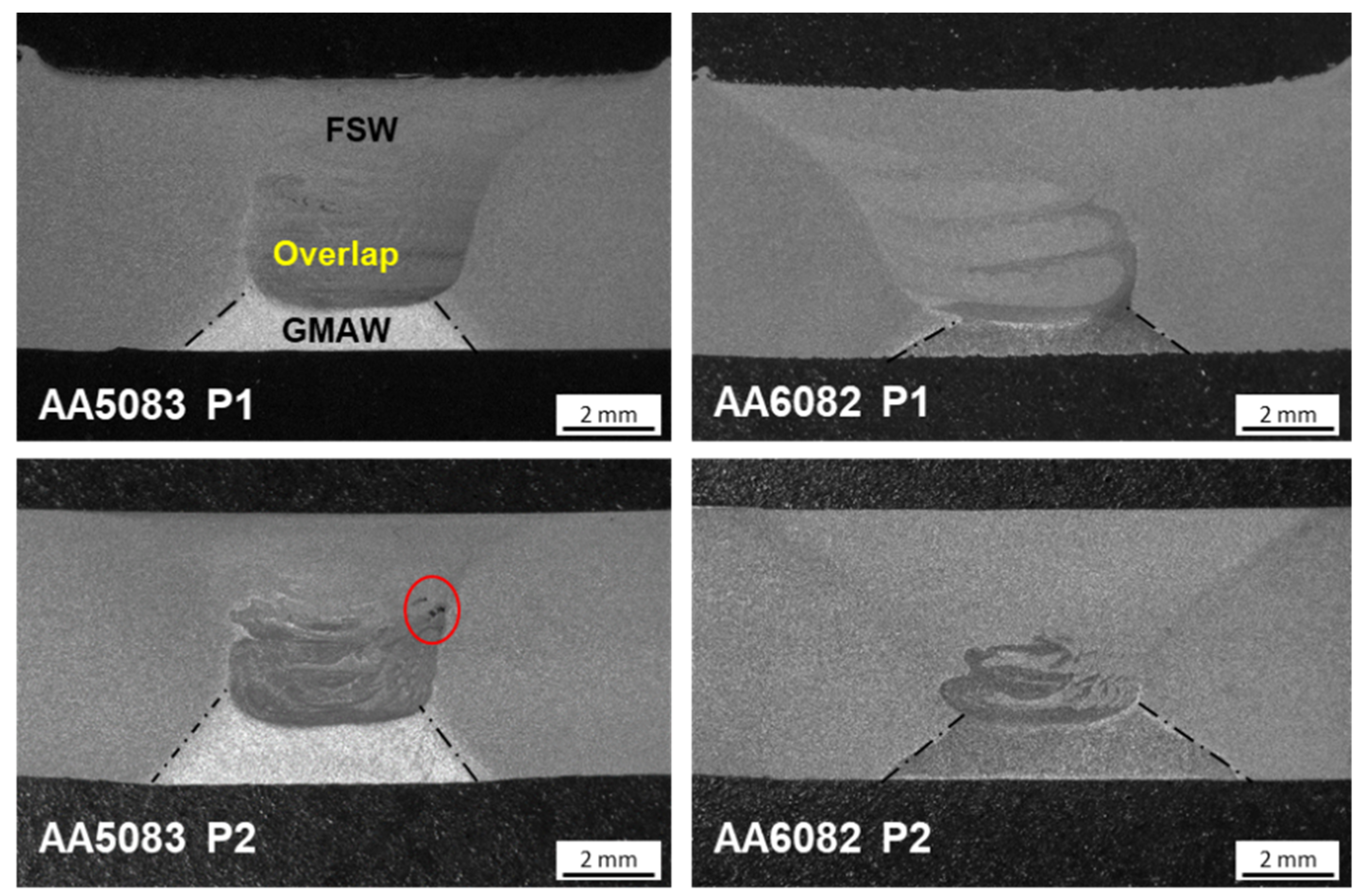
Figure 4 presents the macrographs of the different hybrid joint conditions. The upper region consists of material affected by the FSW process, exhibiting a V-shaped profile due to the difference in diameter between the tool shoulder and the pin. The upper, wider region corresponds to the material influenced by the tool shoulder, while the lower portion narrows as it transitions to the region affected by the tool pin. This central region is known as the Stir Zone (SZ) or Nugget Zone (NZ), where the material underwent an intense thermo-mechanical friction process. Surrounding this zone is the thermo-mechanically–affected zone (TMAZ), which, while not in direct contact with the tool, experienced the combined effects of heat and the mechanical stirring action of the welding tool. Beyond the TMAZ lies the heat-affected zone (HAZ), where the material was influenced only by the elevated temperature during the process [27].
The arc-welded zone is characterized by an inverted V shape (dashed lines), with part of its root region further processed by FSW, forming the overlap zone within the SZ. The stir motion induced by the rotating tool was evident, leading to the mixing of filler metals and base materials, creating distinct zones and layers within the joint.
For the AA5083-H111 joints with a thickness of 6 mm, a difference in friction coverage was observed, with the FSW penetration measuring 4.99 mm for P1 and 5.18 mm for P2. This variation can be attributed to the initial welding positioning defined during the joining setup. Additionally, internal defects were detected in the P2 condition near the lateral interface of the overlap zone with the FSW.
In the case of the AA6082-T6 joints, the FSW coverage was comparable under both parameter conditions, with penetration depths of 4.71 mm for P1 and 4.73 mm for P2. However, the characteristics of the overlap zone varied between the two welding conditions. In P2, this zone appeared more compact and concentrated near the root of the FSW seam. Conversely, in P1, the arc-welded material extended in thinner layers toward the middle of the SZ, suggesting that this condition promoted greater material flow during the process. These differences may also be related to variations in GMAW penetration between the two welding parameters.

3.2. Weld Microstructure

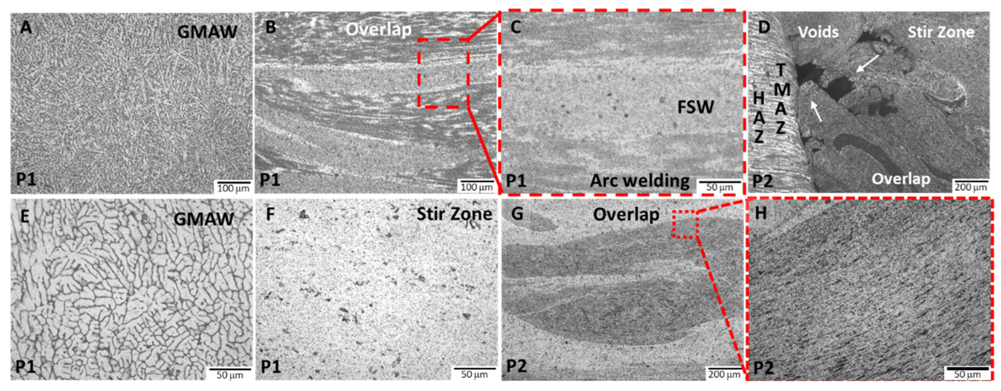
The microstructural analysis of the main welding areas of the AA5083-H111 joints revealed that the different zones were relatively easily distinguished, and distinct features were observed under both welding conditions. The parent material displayed elongated grains aligned along the rolling direction. In contrast, the arc-welded region exhibited a typical cast microstructure, characterized by coarse and dendritic grains, as shown in Figure 5A. As a result of the friction stir process, the SZ presented a refined microstructure consisting of fine, equiaxed grains, significantly smaller than those found in the base material and the arc-welded zone. This grain refinement was a consequence of dynamic recrystallization, driven by the intense plastic deformation and elevated temperatures during welding [27]. The stirring action introduced severe strain, promoting the continuous formation of new grains through dynamic recrystallization.
The overlap zone was composed of layers of the arc-welded zone and patent material, which were subsequently subjected to the FSW process, resulting in a highly refined microstructure (Figure 5B,C). This region exhibited characteristics similar to those of the SZ, with uniformly fine grains. As illustrated in Figure 5D, the TMAZ at the interface with the SZ appeared distorted due to the intense plastic deformation induced by the stirring action during welding. This zone experienced significant plastic strain but did not undergo complete recrystallization, retaining some features of the parent material [24]. Beyond the TMAZ, the HAZ was exposed only to thermal cycles, with minimal plastic deformation, resulting in a grain structure similar to that of the base material.
As observed in the macrographs, the P2 parameter led to the formation of voids at the interface between the overlap zone and the TMAZ, as detailed in Figure 5D. This defect was likely attributed to the specific combination of welding parameters, which resulted in inadequate material mixing.
Similarly to the AA5083-H111 hybrid joints, the overall microstructural features of the AA6082-T6 joints showed minimal variation between the two welding parameter sets. The microstructure produced by the GMAW process displayed coarse grains, formed as a result of the high-temperature thermal cycle, as seen in Figure 5E. In contrast, the SZ generated by the friction process consisted of very fine, equiaxed grains, indicative of continuous dynamic recrystallization [28]. Additionally, inclusions originating from base material were observed to be dispersed throughout this region (Figure 5F).
The overlap zone consisted of layers of original material and arc-welded region which were subsequently subjected to the FSW process (Figure 5G,H). As a result of the frictional stirring, the microstructures of both regions were transformed into a highly refined grain structure. These microstructural characteristics are consistent with findings reported in previous studies on this aluminum alloy [28,29,30].

3.3. Microhardness

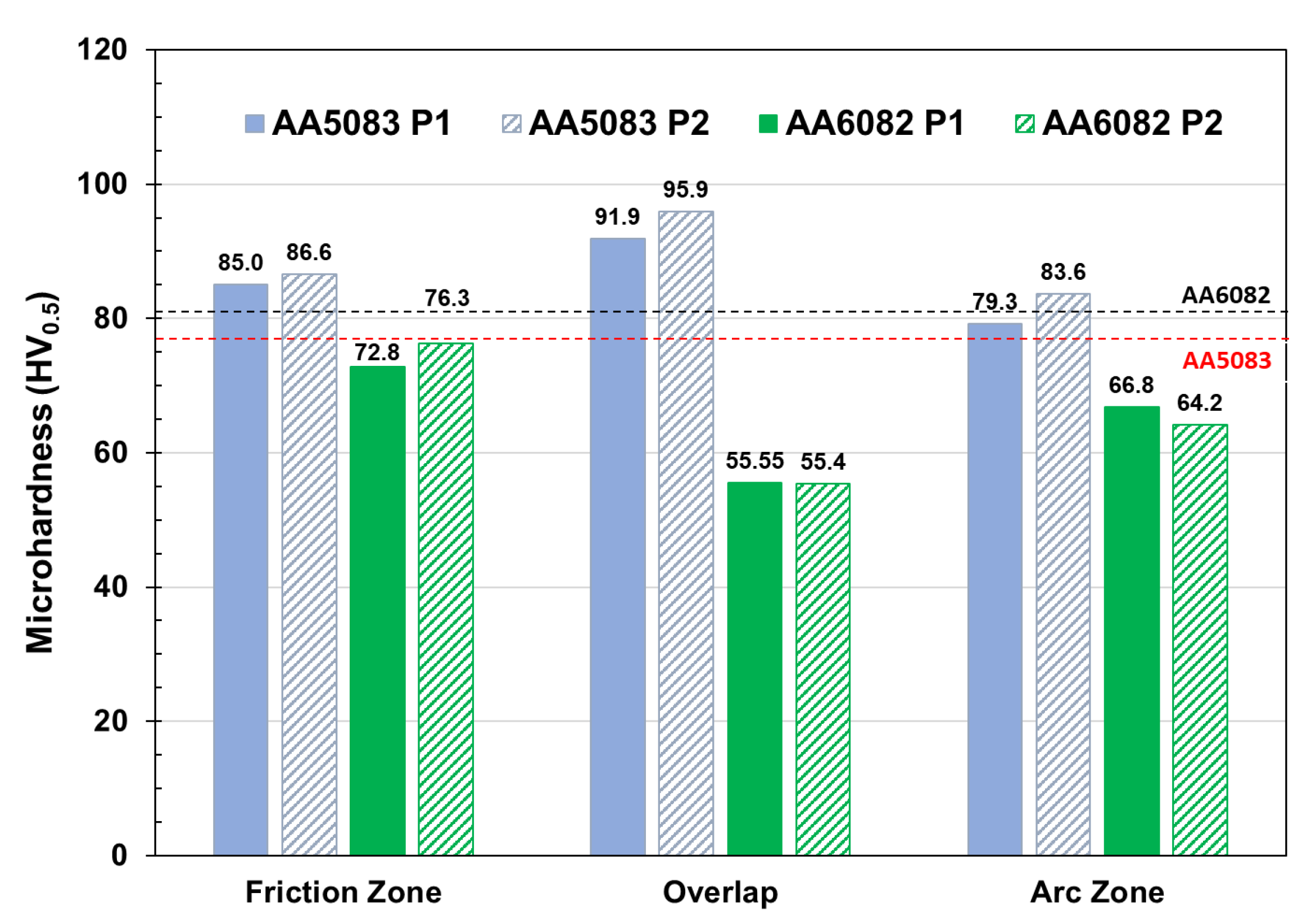
The microhardness values obtained from the hybrid joints are illustrated in Figure 6. For the AA5083-H111 joints, the measurements from both welding parameters showed very similar values. Among the different welding zones, the overlap region recorded the highest hardness (95.9 HV), followed by the friction zone (86.6 HV) and the arc zone (83.6 HV) under the P2 condition. Interestingly, the enhancement achieved in the overlap zone represents a 9.7% increase compared to the friction zone and can be attributed to the high strain rates involved in the FSW process applied to the GMAW joint, which facilitated grain refinement and strain hardening [28]. On the other hand, the lower hardness obtained in the arc zone was associated with the presence of coarse structures resulting from the high temperatures involved [31], as well as the original hardness of the filler metal. Additionally, the comparison with the base material (BM), indicated by the dashed line, revealed that the welding process improved the values in all zones, reaching a maximum of 23% in the overlap zone. The grain refinement observed in the microstructural analysis correlates with this hardness improvement in this zone, where intense plastic deformation and elevated temperatures promoted dynamic recrystallization. The values obtained are in agreement with those reported when arc and friction methods are applied separately. For instance, Kundu et al. [30] performed parameter optimization through a design of experiments approach on the AA5083-H321 alloy, and the optimized joint exhibited a hardness of 77 HV. Similarly, Svensson et al. [28] reported comparable hardness when welding AA5083-H111.
Similarly, evaluating welding parameters in the AA6082-T6 alloy revealed comparable values. However, in this alloy, the friction zone under P1 exhibited the highest hardness (76.3 HV), followed by the arc zone and the overlap region. Unlike the behavior observed in the AA5083-H111, the overlap displayed the lowest values, with reductions of 27% compared to the friction zone and 16% compared to the arc zone. When compared to the BM, the friction zone displayed similar hardness, whereas the other regions showed significantly lower values.
This reduction in hardness in friction stir welds of heat-treatable aluminum alloys is common and has been reported in the literature [28,29,30,32]. In the 6000 series alloys, the hardening mechanism is dominated by precipitation strengthening; however, during welding, the local thermal and mechanical conditions influence the precipitation state. Specifically in the center of the joint, high temperatures and severe plastic deformation typically dissolve the strengthening precipitates (β”-Mg5Si6 and β’-Mg1.7Si) [28,33]. Additionally, because the cooling rates are so high, the time for precipitation is limited, and thus precipitation does not occur, resulting in a noticeable reduction in hardness.
In a study where the friction stir method was applied as a post-welding treatment, El-Fahhar et al. [17] applied a friction surface treatment after MIG welding, resulting in a 46% increase in hardness. The difference in results compared to the present study can be attributed to differences in the application of the friction process. In that case, a rotating pinless tool was used, which was limited to treating only the external surface of the joint rather than the weld material itself. Consequently, the friction treatment affected a smaller area at a lower temperature, resulting in a reduced impact on precipitation evolution and distribution.

3.4. Tensile Testing

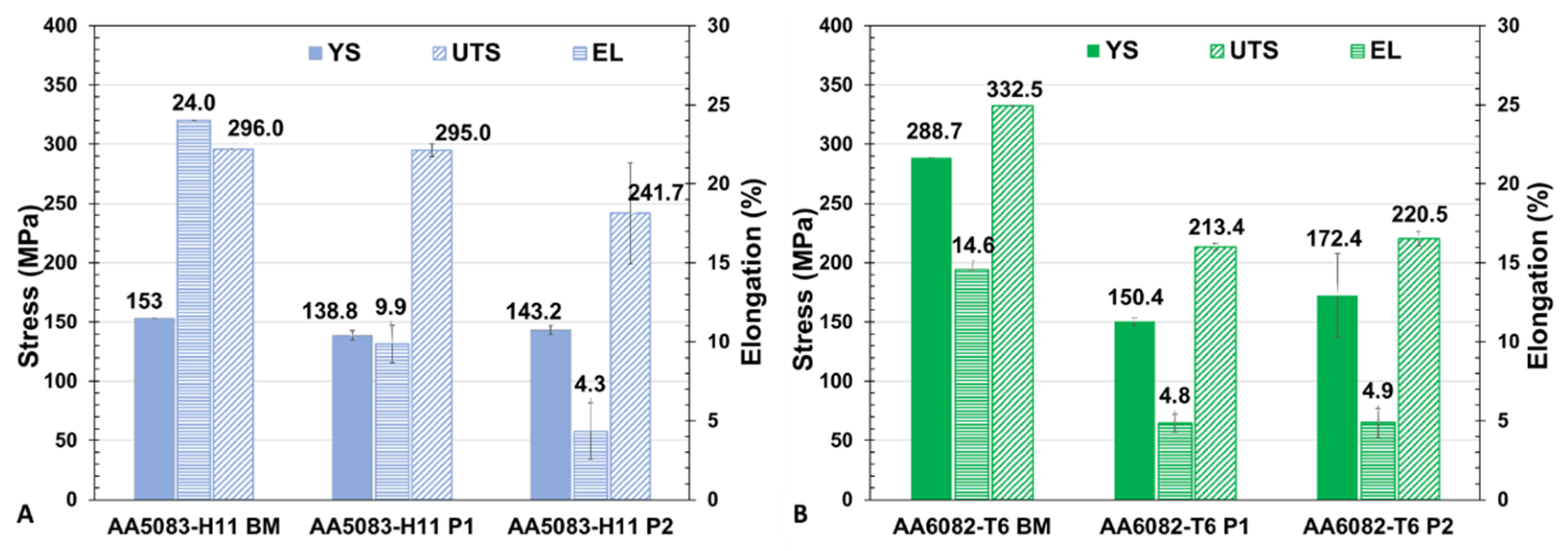
Figure 7 shows the tensile properties obtained from both welding parameters applied to both alloys, where the average standard deviation values of yield strength (YS), ultimate tensile strength (UTS), and elongation (%) were plotted. In general, for the AA5083-H111 welded samples, the comparison of welding parameters showed that P1 exhibited higher values than P2. Specifically, UTS and elongation in P1 were 22% and 130% higher than in P2, respectively, while YS remained similar in both conditions. The fracture locations of the P1 specimens were located in the base material, while the P2 specimens fractured in the center of the joint and in the TMAZ. This behavior may be associated with the presence of voids observed in the macrostructural and microstructural analyses (Figure 4 and Figure 5). Moreover, the P1 condition demonstrated strength values comparable to those of the BM, with a joint efficiency of 99%, which is attributed to the combination of welding parameters that promoted the formation of new fine grains through intense plastic deformation and exposure to elevated temperatures, leading to dynamic recrystallization [17]. Such performance surpasses that observed in AA5083-H321 joints with a thickness of 4.5 mm welded by FSW [32]. In another study comparing arc and FSW technologies applied to 5 mm thick AA5083-H111 sheets, the arc joints achieved a joint efficiency of 82.2%, while the friction joints reached 94.1% [31].
The evaluation of AA6082-T6 revealed a different trend compared to AA5083-H111. In this case, the joints exhibited more uniform strength properties across both welding parameters, with P2 showing only a slight advantage. The differences in YS and UTS between the two conditions were 15% and 3%, respectively. The samples from both conditions displayed the fracture location in the TMAZ. However, compared to the base material (BM), the P2 weldments experienced a notable reduction in strength, with UTS, YS, and elongation reduced by 33.3%, 40.3%, and 66.4%, respectively, compared to the original material.
A reduction in mechanical strength in fusion welds or friction stir welds of this alloy is common and has been widely reported in the literature [34,35,36,37,38,39]. In this heat-treatable aluminum alloy, the mechanical degradation is primarily attributed to the dissolution of strengthening precipitates due to the thermal and mechanical effects of the welding process. Moreover, the fact that fractures occurred in the TMAZ, which experienced substantial thermal exposure without sufficient dynamic recrystallization, suggested that the resulting heterogeneous microstructure, consisting of deformed and partially recrystallized grains, also contributed to the reduction in mechanical strength. Similar findings were obtained in [30].

3.5. Mechanical Behavior in Hydrogen Environment

The experiments conducted to evaluate the susceptibility to hydrogen during in situ tensile testing with pressurized hydrogen gas were carried out in the welded zones of both alloys under P1 welding conditions. Table 4 presents SSRT results obtained for each specimen, and the corresponding values of initial area (A0), initial gauge length (L0), UTS, area reduction (AR), and elongation (ε). These results indicated no significant variations in ultimate tensile strength, area reduction, and elongation between specimens pre-charged and tested in an inert atmosphere (N2) and those tested in a hydrogen atmosphere (H2) for the same material.
For both AA5083-H111 and AA6082-T6 alloys, the mechanical behavior under hydrogen exposure showed no significant deviations compared to inert conditions. The load–displacement curves were consistent across both environments, with no major changes in mechanical properties. In AA5083-H111, a UTS of 308.2 ± 1.9 MPa, AR of 42.0 ± 1.9% and an elongation (ε) of 21.4 ± 1.1%, values that closely match the inert atmosphere results (UTS = 311.7 MPa; AR = 42.3%; ε = 21.8%), thereby indicating negligible loss of strength or ductility. These findings are consistent with Ghorani et al. [40], who reported unchanged tensile strength and elongation for sensitized AA5083 welds under acidified (HA) versus degassed (DNG) SSRT conditions, and with Zhe Liu et al. [41], who observed AR values of approximately 45% in air and 38% under 4 MPa H2 in FSW AA5083 specimens.
For AA6082-T6, a UTS of 213.4 ± 1.7 MPa, AR of 45.6 ± 2.8% and ε of 10.9 ± 0.3%, closely corresponded to the N2 reference (UTS = 215.9 MPa; AR = 41.5%; ε = 11.0%). Papantoniou et al. [42] reported a decrease in elongation from approximately 12% (inert) to 9% under 4 MPa H2 in friction stir processed AA6082-T6, whereas the present SSRTs retained ≈ 11% elongation despite pre-charging at a substantially higher pressure, suggesting an enhanced preservation of ductility.
Additionally, in line with the study by Gao et al. [43], which reported no appreciable differences in SSRT load–displacement curves for AA5083 when comparing hydrogen-charged and inert samples, the in situ SSRT experiments presented in this work (performed after hydrogen pre-charging at 280 bar for 48 h) also revealed no significant hydrogen-induced degradation in the tensile properties of AA5083-H111 or AA6082-T6, thereby underscoring the limited sensitivity of these alloys, or of the SSRT method itself, to detect embrittlement in such welded systems.
In terms of fracture location, the AA5083-H111 alloy consistently failed in the base material at 0°, regardless of the testing environment. Conversely, in the AA6082-T6 alloy, the fracture under inert conditions (N2) occurred at 45° in the base material.
Table 5 presents the hydrogen embrittlement index for each evaluated condition based on the HEE expression (HEE = H2/Air), where for the hydrogen-charged conditions, the average values were used. For the AA6082-T6 joints, the area reduction index exceeded 1, which corresponds to an anomalous result. This discrepancy may be associated with the extraction of samples from different weld beams. Therefore, as the values ranged between 1.0 and 0.97, the classification of both studied alloys falls within the “Negligible” category [26], indicating that the materials may be used in the specified hydrogen pressure and temperature range.
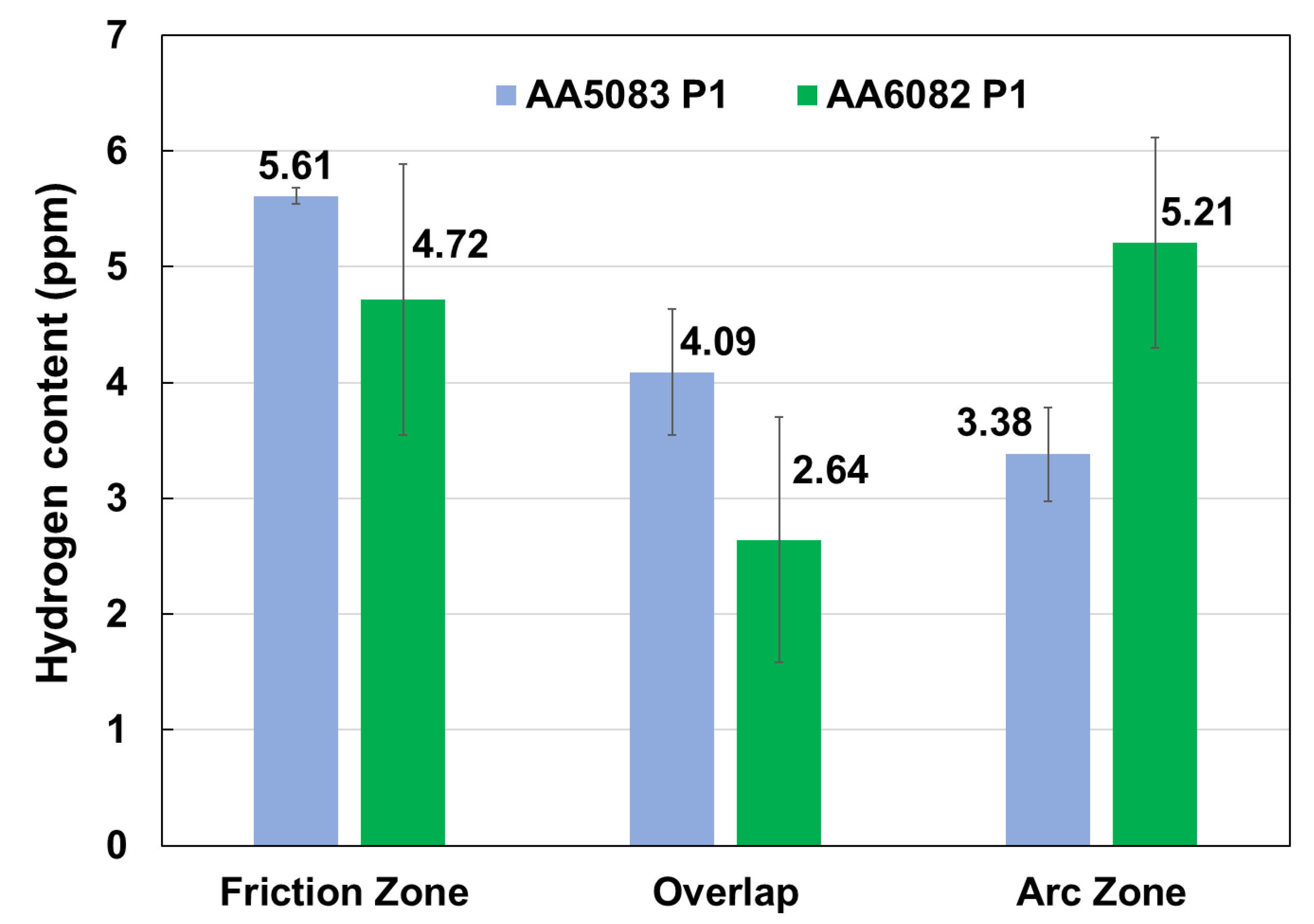
Hydrogen concentrations measured by fusion analysis ranged from 2.6 to 5.6 ppm across all welded zones of both AA5083-H111 and AA6082-T6, with standard deviations ≤ 1 ppm, indicating a high level of repeatability in the results (Figure 8).
In AA5083-H111, the friction zone exhibited the highest hydrogen content (5.61 ± 0.543 ppm). This elevated uptake is attributed to the fine equiaxed grain microstructure produced by severe plastic deformation and dynamic recrystallization, which results in a high density of dislocations and subgrain boundaries that act as efficient hydrogen trapping sites. Similar behavior has been reported [44] in AA5083-H111 subjected to 7% and 15% cold rolling, where increased deformation, leading to a finer grain structure and proliferation of microdefects, enhanced trapping sites and diffusion pathways for hydrogen atoms. Moreover, previous studies of FSW in AA5083-H111 have observed analogous trends [45,46], with fine-grained nugget regions exhibiting the highest hydrogen retention.
By contrast, hydrogen levels decreased by approximately 27% in the overlap zone (4.09 ± 0.50 ppm) and by 40% in the arc fusion zone (3.38 ± 0.46 ppm). In the case of the arc fusion zone, this higher reduction could be attributed to the presence of the filler metal ER 5183, which had a different chemical composition and a coarser, dendritic grain microstructure.
AA6082-T6 displayed a different hydrogen uptake distribution among its weld zones. The arc weld zone showed the highest hydrogen concentration (5.21 ± 1.17 ppm), possibly linked to the filler metal ER4043 (Al–Si-based), which may enhance hydrogen absorption and retention due to its higher affinity for hydrogen compared to Al–Mg fillers [3]. Silicon is known to alter solidification behavior and can form intermetallics that interact with hydrogen and enhance its solubility, and, as exemplified by nanostructured silicon materials capable of storing up to 6.6 wt.% H2 under ambient conditions, which appears to enhance both absorption and retention within dendritic Si-based intermetallics. Notwithstanding this increased uptake, such Si-rich phases are also prone to surface oxidation and require elevated temperatures to remove oxide layers prior to reversible hydrogen release, paralleling the desorption challenges noted for silicon nanostructures [47,48]. By comparison, the FSW weld retained 4.72 ± 1.06 ppm H2, and the overlap zone only 2.64 ± 0.91 ppm, underscoring the primary influence of filler metal chemistry on hydrogen trapping in this Al–Mg–Si system. The approximately twofold increase in hydrogen content from the overlap to the arc zone underscores the critical role of Si incorporation during fusion welding.
Both alloys displayed lower hydrogen concentrations in the overlap zone, despite identical charging conditions. One of the possible explanations is the presence of oxide films [41] or interfacial features formed during the hybrid welding process, which may reduce the number of active diffusion paths or act as partial barriers to hydrogen trapping [42,48]. Further research could focus on investigating the specific role of these interfacial features in mitigating hydrogen absorption.
Based on the findings of this study, the effect of hybrid welding combining GMAW and FSW on high-quality joints in AA5083-H111 and AA6082-T6 alloys was clearly demonstrated. Both alloys were welded under different process parameters and exhibited similar trends in performance. The evaluation of the resulting joints revealed sound mechanical properties and overall satisfactory quality, regardless of the alloy or welding condition.
The metallurgical analysis indicated the typical microstructure obtained from both welding processes. The overlap zone retained the characteristics of a friction-stirred structure, where the cast microstructure initially formed by the arc welding was transformed into highly refined, equiaxed grains. The hardness measurements revealed that this region showed the highest values in AA5083-H111, while this zone displayed a reduction in the AA6082-T6. In terms of strength properties, the AA5083-H111 joints’ welds showed values similar to the BM, reaching a joint efficiency of 99%. On the other hand, for the AA6082-T6, the weldments experienced a reduction in strength, leading to a joint efficiency of 66.7%.
This difference in the response of the joining processes of each aluminum alloy can be attributed to the distinct strengthening mechanisms. As AA5083-H111 is a wrought alloy, its properties are primarily enhanced by grain refinement, where the mechanical work generated during processing significantly reduces the grain size. The high strain rates created an extremely fine-grained structure, and the grain boundaries in this microstructure acted as barriers to dislocation movement, thereby increasing strength.
In contrast, AA6082-T6 is a heat-treatable alloy, in which the primary strengthening mechanism is precipitation hardening. In this alloy, the thermal cycle determines the sequence of precipitation. As high temperatures and severe plastic deformation were involved, the hardening precipitates may have dissolved, and the rapid cooling rates inhibited their reprecipitation.
From the perspective of hydrogen compatibility, the mechanical characterization conducted under high-pressure hydrogen exposure revealed no substantial evidence of embrittlement in either alloy. The SSRT results demonstrated no significant differences in the tensile performance between tests carried out in inert and hydrogen atmospheres, with the hydrogen embrittlement index (HEE) indicating negligible susceptibility. While localized differences in hydrogen uptake were observed, primarily associated with weld zone morphology and alloy-specific metallurgical features, such variations did not compromise the overall mechanical integrity of the joints. These findings suggest that the hybrid GMAW–FSW technique can achieve structurally sound welds with adequate resistance to hydrogen-assisted degradation, reinforcing its suitability for applications involving hydrogen-rich environments. Further research focusing on fatigue performance, long-term hydrogen exposure, and crack propagation under cyclic loading is warranted to comprehensively assess the operational limits of these joints in hydrogen service.
Overall, the outcomes obtained from these mechanical and metallurgical assessments indicated that the hybrid welding process can promote sound joints, demonstrating that this technique has significant potential for industrial applications. Additionally, despite the variation in process parameters, both alloys exhibited similar performance outcomes, highlighting the robustness of the hybrid welding approach. In this regard, more studies are required to investigate other engineering aspects that were not included in the scope of this research, such as fatigue and toughness behaviors.

4. Conclusions

This study evaluated the effect of GMAW–FSW hybrid techniques applied to AA5083-H111 and AA6082-T6 in terms of metallurgical characteristics, mechanical properties, and corrosion resistance. Based on the results obtained, the following conclusions can be drawn:
  • Variations in welding parameters, such as rotation and travel speeds, resulted in similar performance in both alloys.
  • The metallurgical examination revealed the characteristic microstructures associated with each welding process across all conditions. In the overlap zone, the cast structure originally produced by arc welding was altered by the friction-stirring action, resulting in a fine, equiaxed grain structure typical of friction stir welding.
  • In the AA5083-H111 joints, the overlap zone exhibited the highest hardness values (95.9 HV), representing a notable 23% increase compared to the base material. Tensile testing revealed a joint efficiency of 99%, which was primarily attributed to the high strain rates and significant grain refinement induced by the friction stir welding process.
  • The AA6082-T6 joints showed a reduction in hardness across all welded zones compared to the base material, with the overlap zone presenting the lowest value (55.6 HV). The highest joint efficiency achieved in tensile testing was 66.7%. This performance is associated with the dissolution of strengthening precipitates caused by the thermal and mechanical effects of the FSW process.
  • Hydrogen absorption varied across weld zones and alloys, with the FSW zone of AA5083-H111 and the arc-welded zone of AA6082-T6 showing the highest hydrogen content. Nevertheless, hydrogen embrittlement indices remained within the “Negligible” classification for both alloys. Furthermore, SSRT tests revealed no significant differences in fracture location or ductility loss between specimens tested in inert and hydrogen-rich environments, confirming that the hybrid welds maintained their mechanical integrity under hydrogen exposure.
  • The GMAW–FSW hybrid techniques applied to AA6082-T6 and AA5083-H111 successfully modified the microstructure and improved the mechanical properties, indicating the robustness of the hybrid welding approach.

Author Contributions

Conceptualization, M.C., L.G.-S. and E.A.; methodology, M.C., L.G.-S., O.Z. and N.R.; investigation, M.C., L.G.-S., O.Z. and N.R.; writing—original draft, M.C. and L.G.-S.; writing—review and editing, M.C. and L.G.-S.; project administration, M.C. and E.A. All authors have read and agreed to the published version of the manuscript.

Funding

This research work was supported by the Basque Government (Departamento de Desarrollo Económico e Infraestructuras, Programa ELKARTEK) through the ICME23 project (grant KK-2023/00017).

Data Availability Statement

Data will be made available on request.

Acknowledgments

The authors would like to express their gratitude to David González Manso and Imanol Aldazabal for their assistance in conducting the welding experiments. The authors extend their thanks to Aitziber Irazustabarrena and Oihana Amilibia for their expertise in preparing samples for microstructural analysis.

Conflicts of Interest

The authors declare no conflicts of interest.

Abbreviations

The following abbreviations are used in this manuscript:
ARArea Reduction
BMBase Material
CSACanadian Standards Association
CTWDContact-Tip-to-Workpiece Distance
FSWFriction Stir Welding
GMAWGas Metal Arc Welding
GTAWGas Tungsten Arc Welding
HAZHeat-Affected Zone
NZNugget Zone
OMOptical Microscopy
SCCStress Corrosion Cracking
SSRTSlow Strain Rate Testing
SZStir Zone
TMAZThermo-Mechanically–Affected Zone
UTSUltimate Tensile Strength
YSYield Strength

References

  1. Kou, S. Welding Metallurgy; John Wiley & Sons, Inc.: Hoboken, NJ, USA, 2002. [Google Scholar] [CrossRef]
  2. O’Brien, A. Welding Handbook—Welding Processes Part I; American Welding Society: Doral, FL, USA, 2004; Volume 1. [Google Scholar]
  3. Verma, S.; Wu, C.S.; Thakur, L.; Muhammad, N.A.; Li, S. Effect of material position and tool offset on the microstructure and mechanical properties of friction stir welded AA7075/AZ31B with ultrasonic assistance. J. Manuf. Process. 2024, 118, 45–62. [Google Scholar] [CrossRef]
  4. Inácio, P.L.; Ferreira, F.B.; Vilaça, P.; Oliveira, J.P.; Santos, T.G. Assessment of the energetic efficiency of friction stir welding/processing. J. Manuf. Process. 2023, 103, 298–308. [Google Scholar] [CrossRef]
  5. Panagopoulos, C.N.; Georgiou, E.; Giannakopoulos, K.I.; Orfanos, P.G. Effect of pH on stress corrosion cracking of 6082 al alloy. Metals 2018, 8, 578. [Google Scholar] [CrossRef]
  6. Huang, L.; Hua, X.; Wu, D.; Jiang, Z.; Ye, Y. A study on the metallurgical and mechanical properties of a GMAW-welded al-mg alloy with different plate thicknesses. J. Manuf. Process. 2019, 37, 438–445. [Google Scholar] [CrossRef]
  7. Jesus, J.S.; Costa, J.M.; Loureiro, A.; Ferreira, J.M. Fatigue strength improvement of GMAW T-welds in AA 5083 by friction-stir processing. Int. J. Fatigue 2017, 97, 124–134. [Google Scholar] [CrossRef]
  8. Cong, S.; Wu, L.; Wang, Z.; Li, N.; Zhu, Z.; Wang, F.; Zhang, X.; Wang, K.; Xue, P.; Ni, D.; et al. Achieving superior mechanical and corrosion properties in medium-thickness Ti-6Al-4 V alloy joints by back heating assisted friction stir welding below β-phase transformation temperature. Mater. Charact. 2024, 217, 114391. [Google Scholar] [CrossRef]
  9. Chen, J.; Miura, T.; Ushioda, K.; Fujii, H. Effects of microstructure and phosphorus segregation on tensile properties of friction stir welded high phosphorus weathering steel. Mater. Sci. Eng. A 2024, 916, 147315. [Google Scholar] [CrossRef]
  10. Tong, Y.; Dong, B.; Cai, X.; Zhang, H.; Lin, S. Friction stir welding of 2195 Al-Li alloy: Effect of microstructure on joint failure. Mater. Charact. 2025, 224, 115077. [Google Scholar] [CrossRef]
  11. Yu, P.; Wu, C.S.; Shi, L. Analysis and characterization of dynamic recrystallization and grain structure evolution in friction stir welding of aluminum plates. Acta Mater. 2021, 207, 116692. [Google Scholar] [CrossRef]
  12. Akbari, M.; DebRoy, T.; Asadi, P.; Sadowski, T. Recent advances in friction stir welding/processing tools. J. Manuf. Process. 2025, 142, 99–156. [Google Scholar] [CrossRef]
  13. Chludzinski, M.; Vivas, J.; Vázquez-Martínez, J.M.; Del Sol, I.; Begiristain, E.A. Influence of TiC particles on the properties of AA2017 friction surfaced coatings. Adv. Compos. Hybrid Mater. 2025, 8, 222. [Google Scholar] [CrossRef]
  14. Dos Santos, R.E.; Chludzinski, M.; Nunes, R.M.; Marinho, R.R.; Paes, M.T.P.; Reguly, A. Investigation of Friction Hydro-Pillar Processing as a Repair Technique for Offshore Mooring Chain Links. J. Manuf. Mater. Process. 2023, 7, 200. [Google Scholar] [CrossRef]
  15. Lim, Y.C.; Sanderson, S.; Mahoney, M.; Wasson, A.J.; Fairchild, D.P.; Wang, Y.; Feng, Z. Study of mechanical properties and characterization of pipe steel welded by hybrid (friction stir weld + root arc weld) approach. In Friction Stir Welding and Processing VIII; Springer: Cham, Switzerland, 2016; pp. 55–68. [Google Scholar] [CrossRef]
  16. Mahone, M.; Sanderson, S.; Feng, Z.; Steel, R.; Packer, S.; Fleck, D. Friction Stir Welding of Pipeline Steels. In Friction Stir Welding and Proceesing Vll; Springer: Cham, Switzerland, 2013. [Google Scholar]
  17. El-Fahhar, H.H.; Gadallah, E.A.; Habba, M.I.A.; Seleman, M.M.E.-S.; Ahmed, M.M.Z.; Mohamed, A.Y.; Fouad, R.A. Effect of post-weld heat-treatment and solid-state thermomechanical treatment on the properties of the AA6082 MIG welded joints. Sci. Rep. 2024, 14, 4380. [Google Scholar] [CrossRef]
  18. Rao, K.P.; Ram, G.J.; Stucker, B.E. Effect of friction stir processing on corrosion resistance of aluminum–copper alloy gas tungsten arc welds. Mater. Des. 2010, 31, 1576–1580. [Google Scholar] [CrossRef]
  19. Zucchi, F.; Trabanelli, G.; Grassi, V. Pitting and stress corrosion cracking resistance of friction stir welded AA 5083. Werkst. Korros. 2001, 52, 853–859. [Google Scholar] [CrossRef]
  20. Bodaghi, F.; Atapour, M.; Shamanian, M. Assessment of Microstructure and Stress Corrosion Cracking Susceptibility of Multipass Gas Metal Arc Welded Al 5083-H321 Aluminum Alloy. Metallogr. Microstruct. Anal. 2021, 10, 246–256. [Google Scholar] [CrossRef]
  21. Costa, A.M.S.; Oliveira, J.P.; Pereira, V.F.; Nunes, C.A.; Ramirez, A.J.; Tschiptschin, A.P. Ni-based Mar-M247 superalloy as a friction stir processing tool. J. Mater. Process. Technol. 2018, 262, 605–614. [Google Scholar] [CrossRef]
  22. ASTM G129; Standard Practice for Slow Strain Rate Testing to Evaluate the Susceptibility of Metallic Materials to Environmentally Assisted Cracking. ASTM International: West Conshohocken, PA, USA, 2013.
  23. ISO 16573-2; Steel—Measurement Method for Hydrogen Embrittlement Resistance of High Strength Steels—Part 2: Constant Loading Method. ISO: Geneva, Switzerland, 2019.
  24. ASTM G142; Standard Test Method for Determination of Susceptibility of Metals to Embrittlement in Hydrogen Containing Environments at High Pressure, High Temperature, or Both. ASTM International: West Conshohocken, PA, USA, 2010.
  25. CSA (Canadian Standards Association). Standards on Hydrogen Embrittlement; CSA Group: Toronto, ON, Canada, 2014. [Google Scholar]
  26. NASA/TM—2016–218602; Hydrogen Embrittlement. NASA Technical Memorandum: Cleveland, OH, USA, 2016.
  27. Mishra, R.S.; De, P.S.; Kumar, N. Friction Stir Welding and Processing; Springer International Publishing: Cham, Switzerland, 2014. [Google Scholar] [CrossRef]
  28. Svensson, L.E.; Karlsson, L.; Larsson, H.; Karlsson, B.; Fazzini, M.; Karlsson, J. Microstructure and mechanical properties of friction stir welded aluminium alloys with special reference to AA 5083 and AA 6082. Sci. Technol. Weld. Join. 2000, 5, 285–296. [Google Scholar] [CrossRef]
  29. Noga, P.; Skrzekut, T.; Wędrychowicz, M.; Węglowski, M.S.; Węglowska, A. Research of Friction Stir Welding (FSW) and Electron Beam Welding (EBW) Process for 6082-T6 Aluminum Alloy. Materials 2023, 16, 4937. [Google Scholar] [CrossRef]
  30. Essa, A.R.S.; Aboud, A.R.K.; Ahmed, M.M.Z.; El-Nikhaily, A.E.; Easa, A.S.; Habba, M.I.A. Friction stir welding of aluminum alloy 6082-T6 using eccentric shoulder tools to eliminate the need for tool tilting. Sci. Rep. 2025, 15, 8801. [Google Scholar] [CrossRef]
  31. Habba, M.I.A.; Alsaleh, N.A.; Badran, T.E.; Seleman, M.M.E.-S.; Ataya, S.; El-Nikhaily, A.E.; Abdul-Latif, A.; Ahmed, M.M.Z. Comparative Study of FSW, MIG, and TIG Welding of AA5083-H111 Based on the Evaluation of Welded Joints and Economic Aspect. Materials 2023, 16, 5124. [Google Scholar] [CrossRef]
  32. Kundu, J.; Singh, H. Friction stir welding of AA5083 aluminium alloy: Multi-response optimization using Taguchi-based grey relational analysis. Adv. Mech. Eng. 2016, 8, 1687814016679277. [Google Scholar] [CrossRef]
  33. Da Silva, J.; Costa, J.M.; Loureiro, A.; Ferreira, J.M. Fatigue behaviour of AA6082-T6 MIG welded butt joints improved by friction stir processing. Mater. Des. 2013, 51, 315–322. [Google Scholar] [CrossRef]
  34. Chanakyan, C.; Sivasankar, S.; Meignanamoorthy, M.; Ravichandran, M.; Muralidharan, T. Experimental investigation on influence of process parameter on friction stir processing of AA6082 using response surface methodology. Mater. Today Proc. 2020, 21, 231–236. [Google Scholar] [CrossRef]
  35. Mroczka, K.; Pietras, A. FSW characterization of 6082 aluminium alloys sheets. Arch. Mater. Sci. Eng. 2009, 40, 104–109. [Google Scholar]
  36. Adamowski, J.; Gambaro, C.; Lertora, E.; Ponte, M.; Szkodo, M. Analysis of FSW welds made of aluminium alloy AW6082-T6. Arch. Mater. Sci. Eng. 2007, 28, 453–460. [Google Scholar]
  37. Sreenivas, P.; Anil Kumar, R.; Sreejith, P.S. Effect of applied axial force on FSW of AA 6082-T6 aluminium alloys. Int. J. Mech. Eng. Technol. 2017, 8, 88–99. [Google Scholar]
  38. Costa, M.I.; Rodrigues, D.M.; Leitão, C. Analysis of AA 6082-T6 welds strength mismatch: Stress versus hardness relationships. Int. J. Adv. Manuf. Technol. 2015, 79, 719–727. [Google Scholar] [CrossRef]
  39. Qu, G.; Guo, W.; Zhang, H.; Shen, Z.; Zhang, L.; Dai, W.; Xiao, J.; Xue, J.; Zhu, H.; Li, M.; et al. Stress Corrosion Behavior of MIG Welded Joints of 6082-T6 Aluminum Alloy at Different Temperatures. Chin. J. Mech. Eng. 2024, 37, 167. [Google Scholar] [CrossRef]
  40. Ghorani, A.; Itoh, G.; Ohbuchi, T.; Kiuchi, T. Effect of Sensitization on Hydrogen Embrittlement in a 5083 Aluminum Alloy. Mater. Trans. 2022, 63, 1425–1430. [Google Scholar] [CrossRef]
  41. Liu, Z.; Wang, J.; Qin, Z.; Xia, D.-H.; Behnamian, Y.; Hu, W.; Tribollet, B. A mechanistic study on stress corrosion cracking of sensitized AA5083 in a simulated water level fluctuation zone: Combined impedance analysis and tensile tests. Corros. Sci. 2025, 245, 112701. [Google Scholar] [CrossRef]
  42. Papantoniou, I.G.; Karmiris-Obratański, P.; Leszczyńska-Madej, B.; Manolakos, D.E. Investigating the Impact of Friction Stir Processing on the Hydrogen Embrittlement in AA6082-T6 Heat-Treatable Aluminum Alloy. Met. Mater. Int. 2024, 30, 2668–2684. [Google Scholar] [CrossRef]
  43. Gao, W.; Gu, Y.; Chen, L.; Liang, H.; Wang, D.; Seifi, M.; Lewandowski, J.J. Effects of sensitization on environmentally assisted cracking of AA5083-H128 Al–Mg alloy. J. Mater. Res. Technol. 2023, 25, 681–697. [Google Scholar] [CrossRef]
  44. Georgiou, E.P.; Celis, J.P.; Panagopoulos, C.N. The effect of cold rolling on the hydrogen susceptibility of 5083 aluminum alloy. Metals 2017, 7, 451. [Google Scholar] [CrossRef]
  45. Kyriakopoulou, H.P.; Farantos, C.N.; Vazdirvanidis, A.; Markoulis, A.; Xanthis, C.A.; Chatzidouros, E.V.; Pantelis, D.I. Investigation of the Hydrogen Embrittlement Susceptibility of AA5083-H111 and AA6082-T6 Dissimilar Friction Stir Welds. J. Mater. Eng. Perform. 2019, 28, 7687–7701. [Google Scholar] [CrossRef]
  46. Qin, J.; Li, Z.; Ma, M.-Y.; Yi, D.-Q.; Wang, B. Diversity of intergranular corrosion and stress corrosion cracking for 5083 Al alloy with different grain sizes. Trans. Nonferrous Met. Soc. China 2022, 32, 765–777. [Google Scholar] [CrossRef]
  47. Chandra Muduli, R.; Kale, P. Silicon nanostructures for solid-state hydrogen storage: A review. Int. J. Hydrogen Energy 2023, 48, 1401–1439. [Google Scholar] [CrossRef]
  48. Chen, Y.-S.; Huang, C.; Liu, P.-Y.; Yen, H.-W.; Niu, R.; Burr, P.; Moore, K.L.; Martínez-Pañeda, E.; Atrens, A.; Cairney, J.M. Hydrogen trapping and embrittlement in metals—A review. Int. J. Hydrogen Energy 2024, 136, 789–821. [Google Scholar] [CrossRef]
Figure 1. Schematic concept of the hybrid welding technique illustrating the application of GMAW on one side (A), followed by FSW on the opposite side (B).
Metals 15 01005 g001
Figure 2. GMAW robotic welding cell (A) and friction stir welding MTS I-STIR PDS (B) equipment.
Metals 15 01005 g002
Figure 3. Dimensions of the SSRT specimens used for corrosion resistance evaluation. Dimensions in mm.
Metals 15 01005 g003
Figure 4. Macrographs of the AA5083-H111 and AA6082-T6 hybrid joints showing the zones generated by both processes under different welding parameters. The red circle indicates the defects, and the dashed lines highlight the inverted V shape of the arc-welded zone.
Metals 15 01005 g004
Figure 5. Micrographs of the AA5083-H111 (AD) and AA6082-T6 (EH) joints illustrating the different welding zones generated. The white arrows indicate the voids.
Metals 15 01005 g005
Figure 6. Microhardness averages of the different welding zones in the hybrid joints produced with AA5083-H111 and AA6082-T6. The dashed lines correspond to the hardness of the base material.
Metals 15 01005 g006
Figure 7. Strength properties obtained from the AA5083-H111 (A) and AA6082-T6 (B) hybrid joints.
Metals 15 01005 g007
Figure 8. Hydrogen content measured in the different weld zones of AA5083-H111 and AA6082-T6 alloys.
Metals 15 01005 g008
Table 1. Chemical composition of base materials and filler metals, as specified by the manufacturer.
Element (wt.%)MnSiCrCuZnFeTiMg
AA5083-H1110.480.270.070.060.050.320.034.70
AA6082-T60.510.880.010.040.020.360.010.90
ER40430.054.50–6.00---0.80-0.05
ER51830.50–1.000.40---0.40-4.30–5.20
Table 2. Mechanical properties of the aluminum alloys, as specified by the manufacturer.
PropertiesAA5083-H111AA6082-T6
Ultimate tensile strength (MPa)296.00332.50
Yield strength (MPa)153.00288.70
Maximum elongation (%)24.0014.56
Table 3. Friction stir welding process values.
AlloyAA6082-T6AA5083-H111
Welding Parameter1212
Rotation speed (rpm)1000800600700
Transversal speed (mm/min)150300175300
Heat input (J/mm)711.7351.7473.7278.4
Table 4. SSRT test results in both inert and hydrogen atmosphere environments.
AlloySample 1Initial Area (A0) (mm2)Initial Length (L0) (mm)UTS
(MPa)
AR
(%)
ε
(%)
AA5083-H111T01_N217.630.1311.742.321.8
T02_H217.929.8306.539.922.6
T03_H217.930.0307.843.520.5
T04_H217.730.1310.242.721.1
AA6082-T6T01_N218.230.0215.941.511.0
T02_H217.929.3213.946.111.0
T03_H218.129.7211.448.111.2
T04_H217.729.1214.842.710.6
1 N2 = inert atmosphere and H2 = hydrogen atmosphere.
Table 5. Hydrogen embrittlement index for each material.
AlloyHEE σUTSHEE σARHEEe
AA5083-H1110.98870.99440.9795
AA6082-T60.98811.10040.9908
Disclaimer/Publisher’s Note: The statements, opinions and data contained in all publications are solely those of the individual author(s) and contributor(s) and not of MDPI and/or the editor(s). MDPI and/or the editor(s) disclaim responsibility for any injury to people or property resulting from any ideas, methods, instructions or products referred to in the content.