1. Introduction
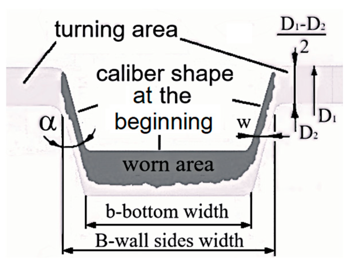
The rolling process, using grooved (caliber) rolls, is used to produce a wide range of profiles. The durability of these rolls is a crucial aspect of their performance, particularly because these rolls are subjected to significant mechanical and thermal stresses. Several factors influence their durability including groove design, material properties, operational conditions, wear, and turning. During the rolling process, friction between the rolls and the workpiece causes non-uniform wear of the caliber-shaped grooves, resulting in the loss of their required form, as shown in
Figure 1.
As shown in
Figure 1, the points of extreme wear determine the total depth of subsequent turning. The required turning depth can be determined from Equation (1), as referenced in [
1], where D
1—initial diameter; D
2—reduced diameter due to turning;
—caliber slope; and
w—layer thickness. Wear-induced turning is an undesirable phenomenon, as it increases production costs and reduces the roll’s fatigue life.
Roll failure leads to production downtime and significantly increases overall operational costs. Consequently, research into the causes of roll failure has intensified, with particular focus on the influence of rolling parameters. Numerous researchers have investigated the wear mechanisms of rolling mill rolls [
2,
3,
4,
5].
The study in [
6] presents a failure investigation and crack characterization of a spalled work roll in a hot strip mill. Backup roll failures, including cracking, are examined in [
7]. The study in [
8] presents a research methodology to gain better control of the process, allowing innovation in the production of profiles with more complex geometries and new materials. The study in [
9] proposes a comprehensive approach to analyzing coupled wear and fatigue damage using a method based on the Manson–Coffin equation, a modified slope formula, and the Miner criterion.
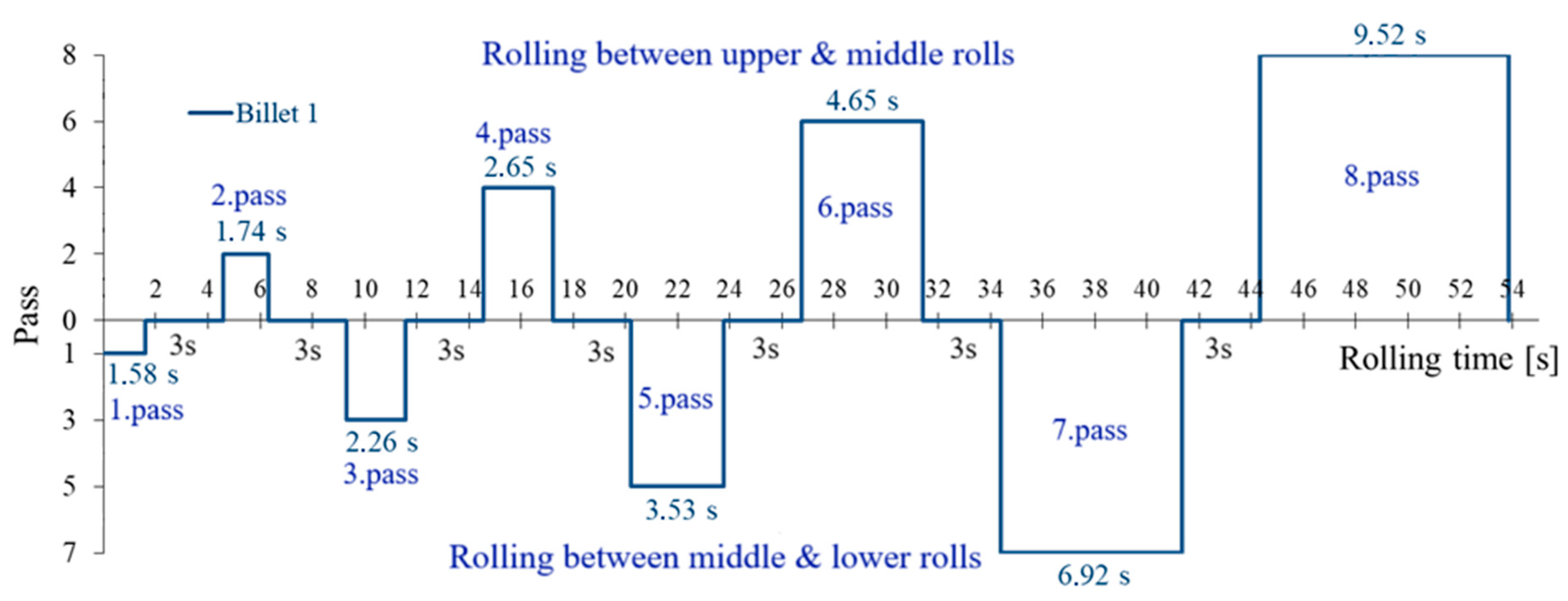
A three-high roughing mill stand is commonly used in hot-rolling processes to reduce the thickness of steel billets while extending their length. This configuration is particularly effective for handling billets with an initial cross-section of 100 mm square and an initial length of 3000 mm. In this case, three (3) rolls were used to reduce 100 mm square billets with a cross-sectional area of 9850 mm
2 to an oval shape measuring 58 × 20 mm, with a final cross-sectional area of 1075 mm
2, over eight passes, as shown in
Figure 2 and
Table 1 [
10]. The roll speed was 120 rpm.
The dimensions of the new rolls were as follows: total length of 2300 mm, barrel length of 1400 mm, and barrel diameter of 450 mm. The upper roll had a diameter of 450 mm, the middle roll 445 mm, and the lower roll 440 mm. The minimum effective diameter of the rolls was 380 mm.
The rolling process begins with a single billet, as illustrated in the diagram shown in
Figure 3.
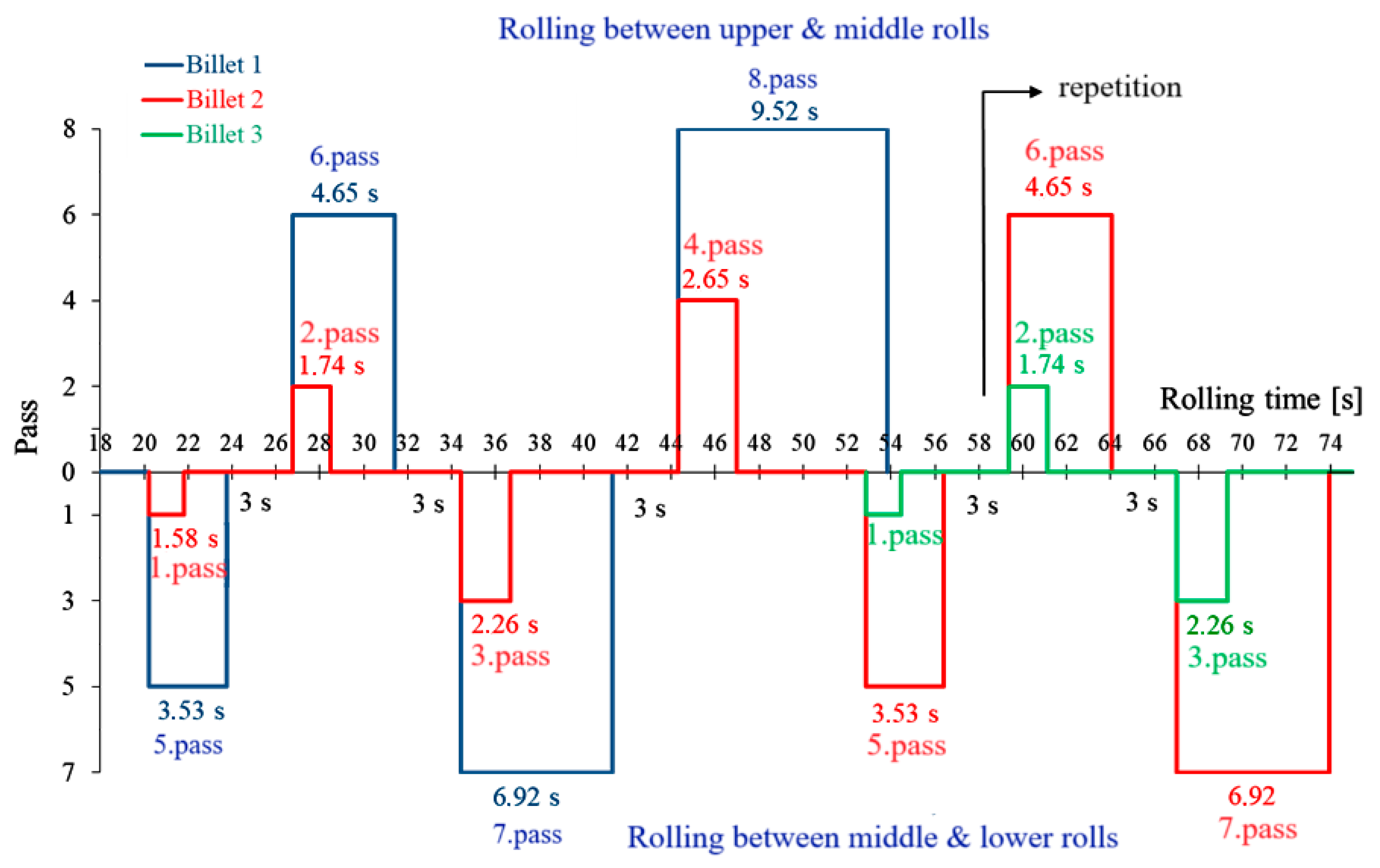
Usually, rolling was carried out with two billets and occasionally with three. The diagram in
Figure 4 illustrates the rolling process with two and three billets. As shown, rolling with two billets began at 20.23 s.
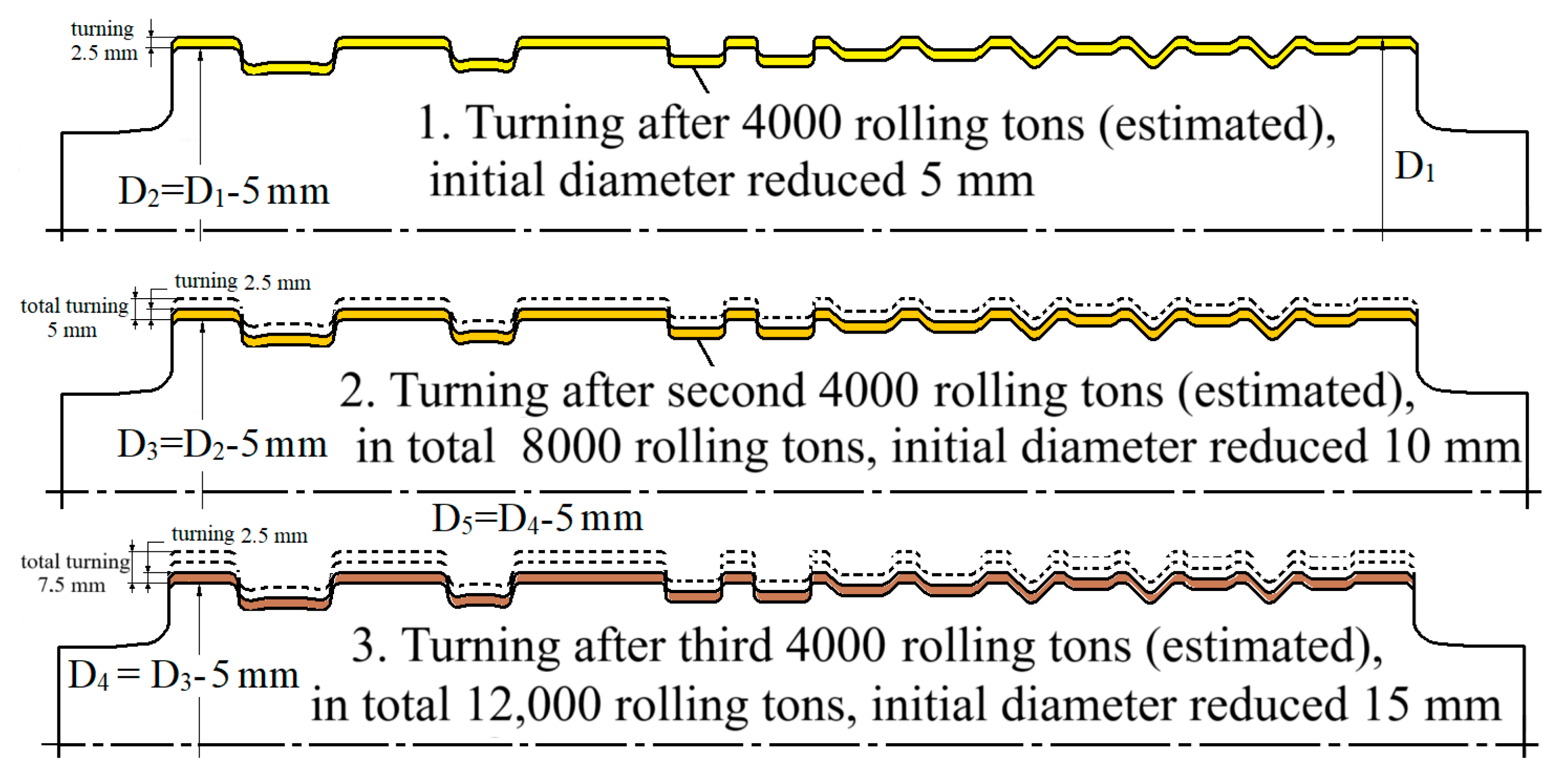
Caliber roll wear ‘life’ is measured in tons of hot-rolled steel per millimeter of machined roll diameter (t/mm) [
1]. In this case, roll remachining due to wear was estimated after processing 4000 tons of hot-rolled steel. It was also estimated that the roll wear “life” would extend till 16.000 rolling tons of steel, which corresponds to a three-time reduction in roll diameter through turning. Typically, each turning operation reduced the roll diameter by 5 mm, depending on the extent of groove wear; see
Figure 5.
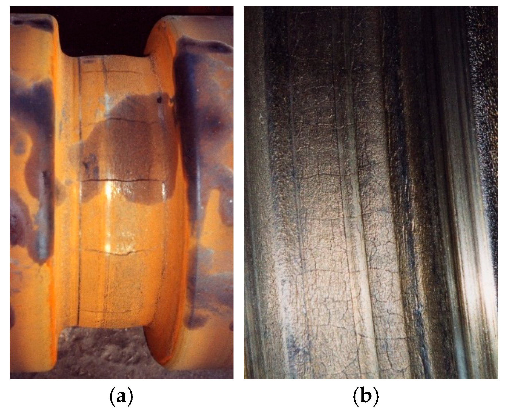
Sometimes, thermal cracks may appear around the perimeter of a groove of a certain caliber (see
Figure 6). The occurrence and distribution of these cracks vary depending on the caliber and the individual roll. During wear turning, thermal cracks are removed along with the worn material.
5. Impact of Wear-Induced Diameter Reduction on Roll Fatigue Life
Due to wear, the diameter of the middle roll is reduced by 5 mm after each 4000 tons of rolling, decreasing from 445 mm to 430 mm. To evaluate the effect of this reduction, the same numerical model of the middle roll was used to determine local stresses for four-barrel diameters: 440 mm, 435 mm, and 430 mm. The corresponding stress spectra in pass groove 7a, calculated for 4000 tons of rolling, are presented in
Figure 13.
The next facts are visible from the diagram in
Figure 13:
After each turning of 2.5 mm due to wear, corresponding to a 5 mm reduction in roll diameter, the maximum stress amplitude increases by approximately 4%. For example, after the first turning—reducing the diameter from the initial 445 mm to 440 mm—the maximum stress amplitude increases from 90 MPa to 94 MPa.
After 16,000 rolled tons—the estimated practical working life—which corresponds to three turnings of 2.5 mm each due to wear and results in a total roll diameter reduction of 15 mm, the maximum stress amplitude increases by approximately 12.2%, from 90 MPa to 101 MPa.
The number of cycles at the maximum stress amplitude of 101 MPa is 53,300, which is approximately nine times fewer than the material’s fatigue life at the same stress level—465,000 cycles.
The calculation of fatigue life using the elementary Miner’s rule showed a reduction of approximately 1.5 times, from 3,075,567 to 2,042,000 cycles. Furthermore, when compared with the stress spectrum for 4000 rolled tons, the service life at a maximum stress amplitude of 101 MPa exceeds twice the maximum number of cycles in the stress spectrum (942,155).
It should also be noted that turning not only reduces the roll diameter but also removes any potential thermal cracks. After material removal, the roll—now with a reduced diameter—can be considered effectively new, with a different size and, consequently, a new fatigue life.
Ultimately, these findings indicate the potential for further diameter reduction.
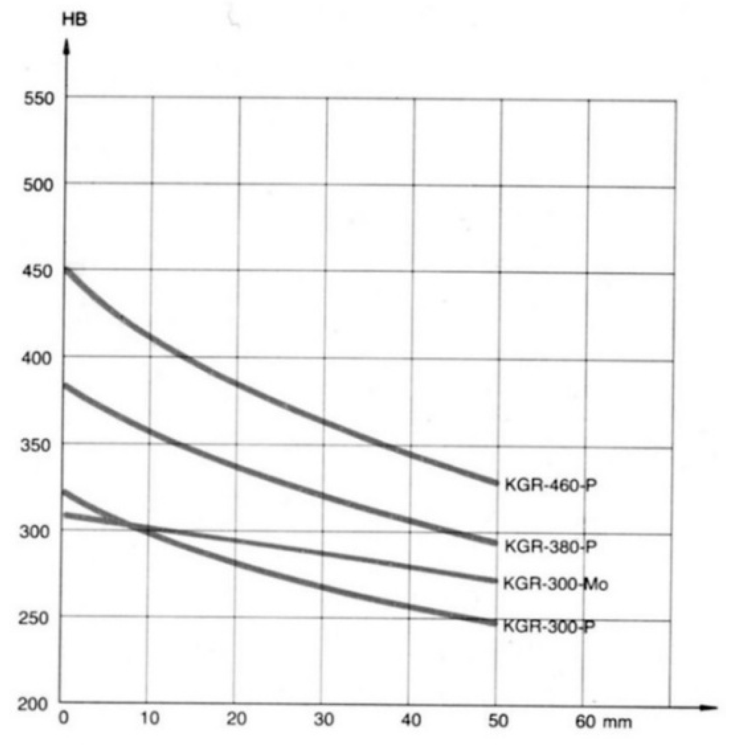
Further reduction in the roll diameter depends on the design of the rolling mill stand and the hardness of the rolls. According to the study in [
7], the maximum reduction in roll diameter is from 450 mm to 380 mm (see
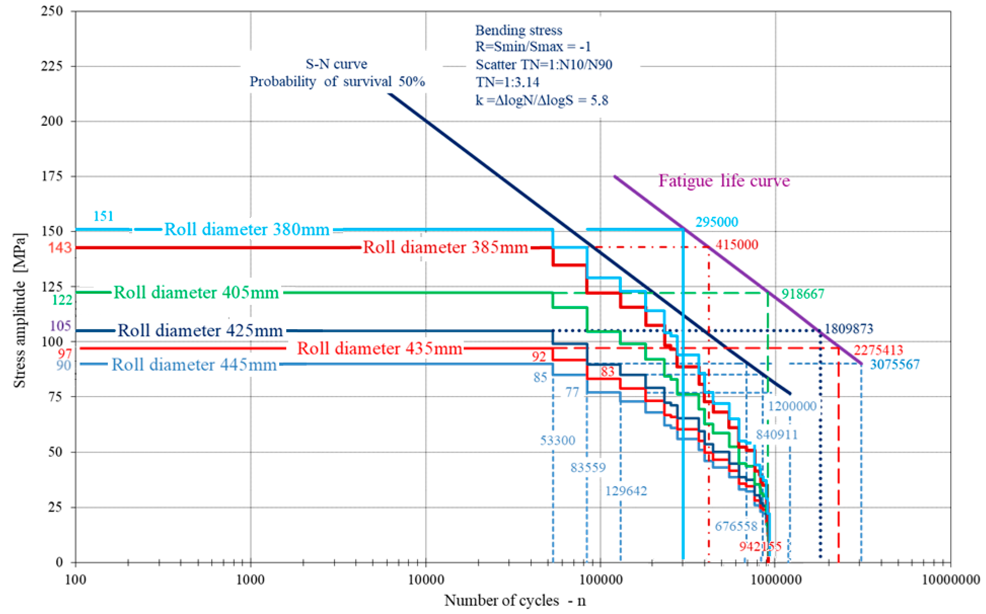
Figure 7). Hardness measurements of the cut ring indicate that a similar reduction in roll diameter may be possible. To determine the maximum possible reduction in the roll diameter, the same numerical model of the middle roll was used to calculate local stresses for the following diameters: 405 mm, 385 mm, and 380 mm. The corresponding stress spectra in pass groove 7a for all six diameters are presented in
Figure 14.
Figure 14 indicates that a further reduction in roll diameter by 20 mm—starting from a new initial diameter of 425 mm down to 420 mm, 415 mm, and 410 mm—is feasible, with 405 mm representing the limiting diameter for possible reduction. This would allow for an additional 16,000 tons of rolling to be produced using the same rolls.
6. Concluding Remarks
During rolling, friction causes wear in the grooves of the caliber rolls, necessitating turning to restore their shape—an undesirable process that increases operational costs and shortens the rolls’ fatigue life. In this case, roll remachining due to wear was required after 4000 tons of hot-rolled steel, with wear life extending up to 16,000 tons—equivalent to three turning operations, each reducing the roll diameter by 5 mm depending on groove wear, resulting in a total diameter reduction of 15 mm.
Stress analysis showed that a 15 mm reduction in roll diameter results in an approximate 12.2% increase in maximum stress amplitude, rising from 90 MPa to 101 MPa. At this elevated stress level, the number of cycles in the stress spectrum is 53,300—about seven times fewer than the material’s fatigue life of 465,000 cycles. Using Miner’s rule, the estimated fatigue life decreases by approximately 1.5 times, from 3,075,567 to 2,042,000 cycles. Although the fatigue life is significantly reduced, the analysis indicates that fatigue failure should still be avoided under normal operating conditions without overload. Furthermore, the results suggest that additional diameter reduction may still be feasible, as the predicted fatigue life at 101 MPa (2,042,000 cycles) exceeds twice the maximum number of cycles in the stress spectrum (942,155).
Based on the mill’s design, the roll diameter can be reduced from 450 mm to a minimum of 380 mm, in accordance with rolling process requirements. Hardness measurements of the actual roll indicate that such a reduction is feasible. Further analysis confirmed that an additional 20 mm diameter reduction is both feasible and reasonable, making 405 mm the limiting diameter for possible reduction in this case study. This would enable the production of an additional 16,000 tons of rolled steel using the same rolls.
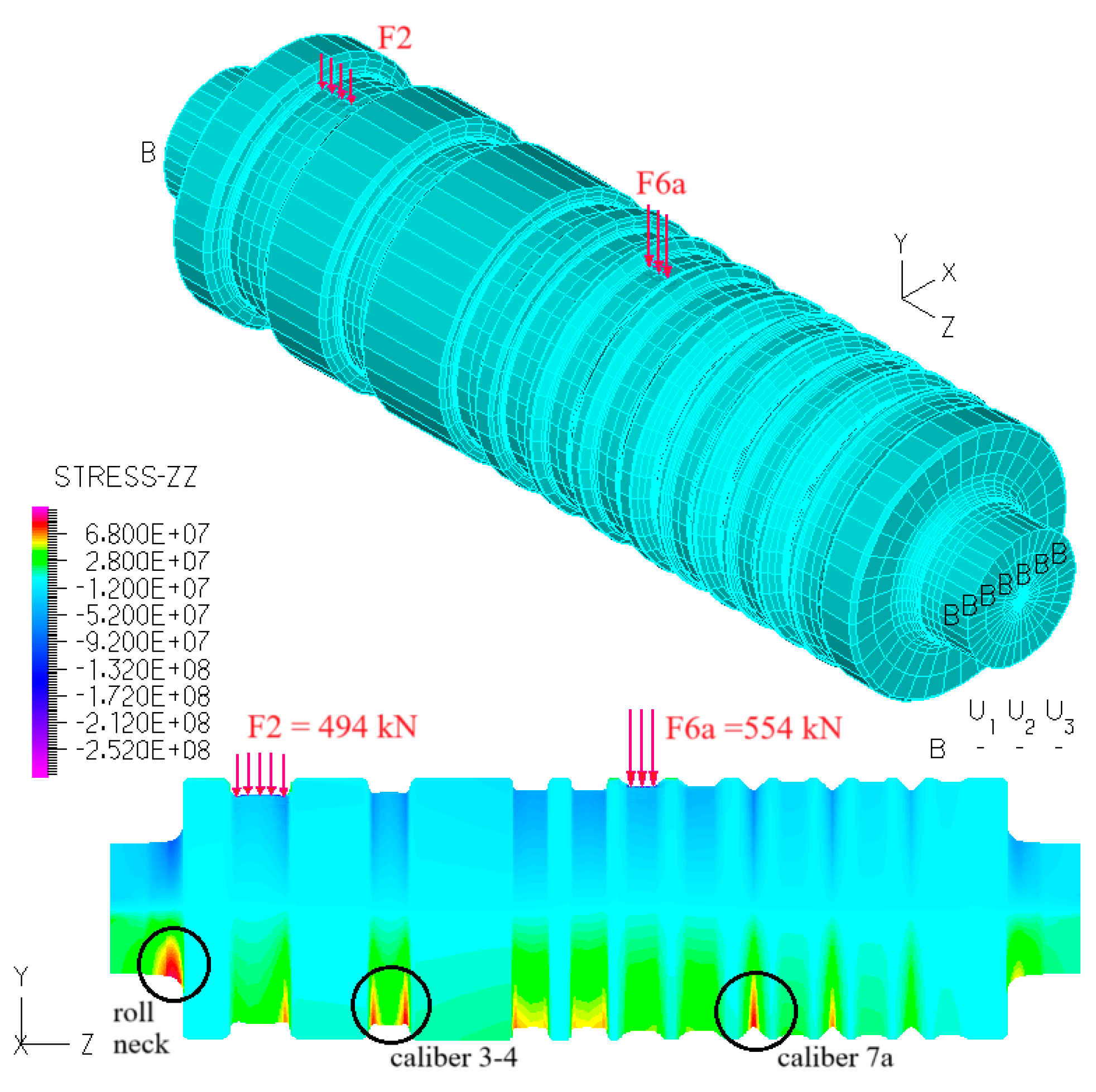
Stress analysis was performed on the middle roll, as it carries twice the load of the upper and lower rolls. For the middle roll, the highest corresponding stresses in pass grooves 3–4 and 7a occur during rolling between the upper and middle rolls in pass grooves 4 and 8, as well as 2 and 6. Since the upper roll’s diameter is 5 mm larger than the middle roll’s, the corresponding stresses in pass groove 3–4 are assumed to be lower. For the same reason, there are no significant stresses in pass groove 7a of the lower roll during rolling in pass grooves 4 and 8, or 2 and 6.
To achieve optimal roll fatigue life and maximize utilization, this type of analysis should be integrated into the roller design process.
Author Contributions
Conceptualization, F.L. and Ž.D.; methodology, F.L. and Ž.D.; software, F.L., Đ.D. and B.L.; validation, F.L., Ž.D. and Đ.D.; formal analysis, F.L. and Ž.D.; investigation, F.L. and Ž.D.; resources, B.L.; data curation, F.L., Đ.D. and B.L.; writing—original draft preparation, F.L.; writing—review and editing, F.L., Ž.D, Đ.D. and B.L.; visualization, F.L., Đ.D. and B.L.; supervision, Ž.D., Đ.D. and B.L. All authors have read and agreed to the published version of the manuscript.
Funding
This research received no external funding.
Data Availability Statement
The original contributions presented in this study are included in the article. Further inquiries can be directed to the corresponding author.
Conflicts of Interest
The authors declare no conflict of interest.
References
- Čaušević, M. Obrada Metala Valjanjem; Veselin Masleša: Sarajevo, Bosnia and Herzegowina, 1983. [Google Scholar]
- Wei, J.; Zhao, A. Research on the Prediction of Roll Wear in a Strip Mill. Metals 2024, 14, 1180. [Google Scholar] [CrossRef]
- Niekurzak, M.; Kubinska-Jabcon, E. Assessment of the Impact of Wear of the Working Surface of Rolls on the Reduction of Energy and Environmental Demand for the Production of Flat Products: Methodological Approach. Materials 2022, 15, 2334. [Google Scholar] [CrossRef] [PubMed]
- Ścibisz, K.; Kazmierski, T.; Krawczyk, J. A Roll’s Wear During Hot Rolling of High-Silicon Steel and its Impact on the Quality of a Strip’s Profile. Tribologia 2023, 305, 95–102. [Google Scholar] [CrossRef]
- Zhang, X.; Li, Z.; Zhang, B.; Wang, J.; Elmi, S.A.; Bai, Z. Optimization and Finite Element Simulation of Wear Prediction Model for Hot Rolling Rolls. Metals 2025, 15, 456. [Google Scholar] [CrossRef]
- Palit, P.; Sri, K.P.; Kayal, N.; Bairwa, H.O.; Monia, S.; Gokarn, P.; Kumar, A. Failure investigation and crack characterization of spalled work roll in hot strip mill. J. Fail. Anal. Prev. 2024, 24, 1522–1532. [Google Scholar] [CrossRef]
- Servin-Castañeda, R.; Arreola-Villa, S.A.; Perez-Alvarado, A.; Calderón-Ramos, I.; Torres-Gonzalez, R.; Martinez-Hurtado, A. Influence of Work Hardening on the Surface of Backup Rolls for a 4-High Rolling Mill Fractured during Rolling Campaign. Materials 2022, 15, 3524. [Google Scholar] [CrossRef] [PubMed]
- Pérez-Alvarado, A.; Arreola-Villa, S.A.; Calderón-Ramos, I.; Servín Castañeda, R.; Mendoza de la Rosa, L.A.; Chattopadhyay, K.; Morales, R. Numerical Simulation of the Hot Rolling Process of Steel Beams. Materials 2021, 14, 7038. [Google Scholar] [CrossRef] [PubMed]
- Wang, J.; Chang, J.; Zhang, M.; Li, W.; Peng, Y. Analysis of fatigue damage of hot rolling work rolls coupled with wear effect. J. Manuf. Process. 2024, 131, 1423–1436. [Google Scholar] [CrossRef]
- Steelworks Split. Designs and Technological Rules; Steelworks Split: Split, Croatia, 2000. [Google Scholar]
- Domazet, Ž.; Lukša, F.; Stanivuk, T. An optimal design approach for calibrated rolls with respect to fatigue life. Int. J. Fatigue 2014, 59, 50–63. [Google Scholar] [CrossRef]
- Kurt, G.; Yaşar, N. Comparison of experimental, analytical and simulation results for hot rolling of S275JR quality steel. J. Mater. Res. Technol. 2020, 9, 5204–5215. [Google Scholar] [CrossRef]
- Barbosa, J.V.; Santos, A.A. Calculation of rolling force in the hot strip finishing mill using an empirical model. Tecnol. Metal. Mater. Mineração 2020, 17, 149–156. [Google Scholar]
- Yang, Y.; Peng, Y. Theoretical Model and Experimental Study of Dynamic Hot Rolling. Metals 2021, 11, 1346. [Google Scholar] [CrossRef]
- Wu, H.; Yuan, S.; Lin, F.; Ren, M.; Yan, J.; Zhou, M.; Xing, Z.; Jiao, S.; Jiang, Z. Analysis of Rolling Force and Friction in Hot Steel Rolling with Water-Based Nanolubrication. Steel Res. Int. 2025, 96, 2400229. [Google Scholar] [CrossRef]
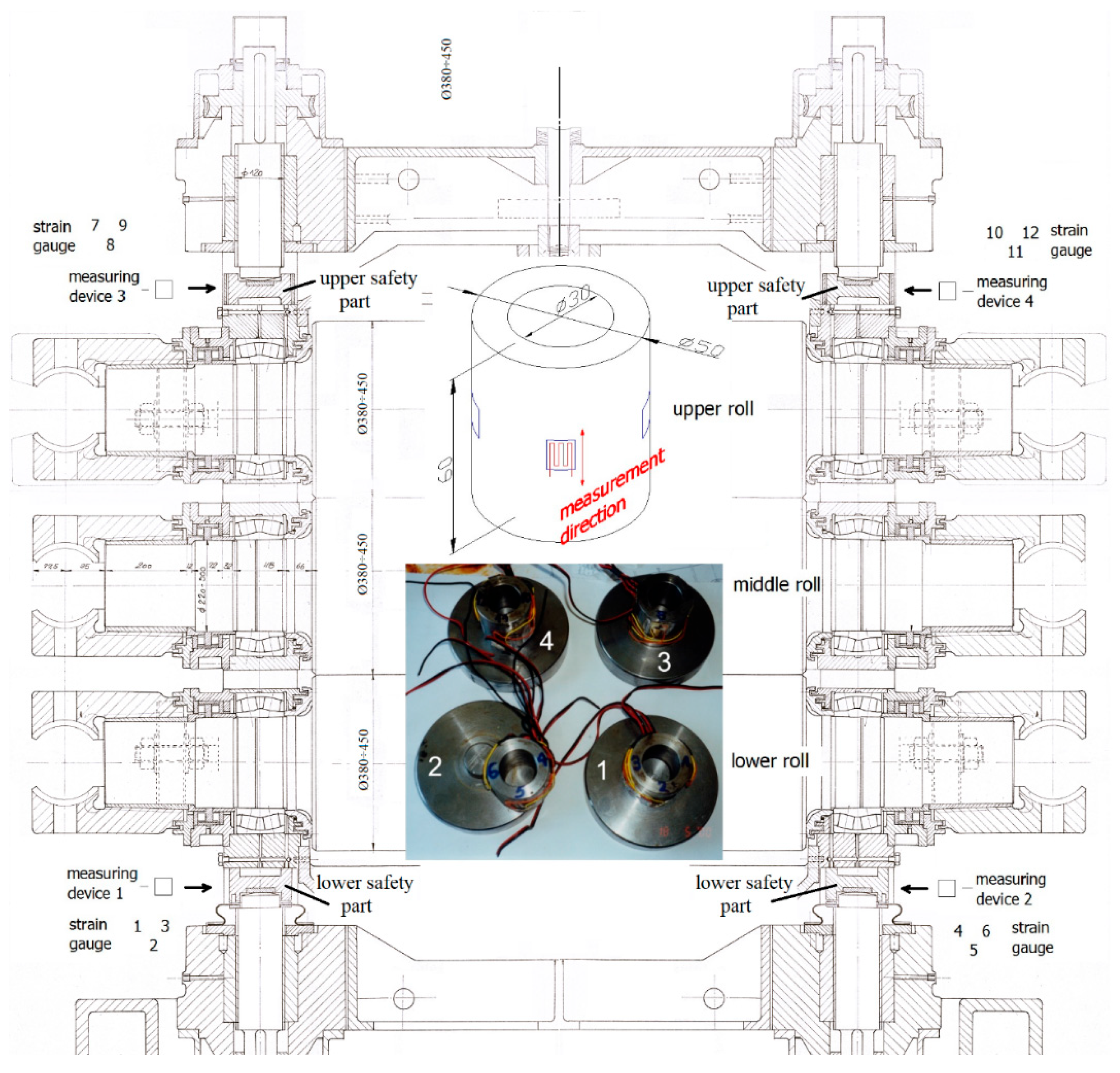
- Domazet, Ž.; Lukša, F. Experimental determination of the rolling force on the rolls with grooves. In Proceedings of the 22-nd Symposium “DANUBIA-ADRIA” on Experimental Methods in Solid Mechanics, Parma, Italy, 28 September–1 October 2005. [Google Scholar]
- Domazet, Ž.; Lukša, F.; Bugarin, M. Fatigue Strength of the Rolls with Grooves. Appl. Mech. Mater. 2013, 459, 330–334. [Google Scholar] [CrossRef]
| Disclaimer/Publisher’s Note: The statements, opinions and data contained in all publications are solely those of the individual author(s) and contributor(s) and not of MDPI and/or the editor(s). MDPI and/or the editor(s) disclaim responsibility for any injury to people or property resulting from any ideas, methods, instructions or products referred to in the content. |
© 2025 by the authors. Licensee MDPI, Basel, Switzerland. This article is an open access article distributed under the terms and conditions of the Creative Commons Attribution (CC BY) license (https://creativecommons.org/licenses/by/4.0/).


