Article

Deformation and Energy Absorption Characteristics of Metallic Thin-Walled Tube with Hierarchical Honeycomb Lattice Infills for Crashworthiness Application

1
UniSA STEM, University of South Australia, Mawson Lakes, SA 5095, Australia
2
Future Industries Institute, University of South Australia, Mawson Lakes, SA 5095, Australia
*
Author to whom correspondence should be addressed.
Metals 2025, 15(6), 629; https://doi.org/10.3390/met15060629
Submission received: 28 April 2025 / Revised: 26 May 2025 / Accepted: 30 May 2025 / Published: 2 June 2025

Abstract

This paper investigates the axial deformation characteristics and crashworthiness of thin-walled metal tubes (TWT) reinforced with Polyetherketoneketone (PEKK) honeycomb lattice structures consisting of bio-inspired hierarchical cellular topological features. Experimentally validated numerical results revealed that the specific energy absorption capacity (SEA) of these composite structures increased with filler volume corresponding to a specific cellular topology. This includes the bio-inspired hierarchical sparse (BHS) topology, which registered a remarkable improvement in SEA over the hollow tube of 202%. In contrast, the central (BHC) topology deformed in an unstable hex-dominated pattern and triggered catastrophic failure of the composite in global bending mode. Furthermore, rigid cells were shown to drastically increase the initial peak force (IPF), while cells with low stiffness were beneficial for maintaining a low level of IPF and moderately improving SEA. Moreover, the rib and wall thickness of the BHS honeycomb cells were suitably tailored to increase the SEA by 2.1%, while simultaneously reducing the IPF by 3.7%. These findings suggest that multi-functional mechanical attributes of PEKK hierarchical honeycomb lattice fillers can mutually benefit thin-walled tubes with superior energy absorption capability and lightweight features over conventional lattice-filled tubes or a hollow tube.

1. Introduction

Modern vehicles are manufactured with stringent safety policies which require a large energy dissipation capacity during a high-speed impact. The thin-walled metal tube is effective at absorbing the impact energy and highly reliable for commercial applications given its simple geometry, decent strength-to-weight ratio and low cost. Typically oriented axially along the direction of impact to maximise the energy absorption capacity, its traditional design limitations [1,2], loading characteristics [3,4,5] and deformation mechanics [6,7,8,9] have been extensively studied. To increase its energy absorption capacity, the empty hollow space is frequently fitted with reinforcements such as multi-cells [10,11,12], bi-tubular structures [13,14] and nested tubes [15]. However, solid structural supports are known to be bulky and could rapidly reduce the crashworthiness performance of a thin-walled tube as its mass increases. Therefore, novel designs are required to address the deficiencies of traditional thin-walled tubes.
Foam and honeycomb are lightweight cellular structures with a decent capacity to dissipate energy without a significant increase in mass [16,17,18], and are often deployed as filler materials for thin-walled tubes. In particular, the thin-walled geometry of the honeycomb structure provides it with a high strength-to-weight ratio which offers several mechanical benefits. For instance, Hussein et al. [19] demonstrated that the cell walls of a honeycomb assist in the compression of housing a thin-walled tube with increased progressive folds and higher energy absorption capacity. Wang et al. [20] determined that the matching interaction between the evolving folds inside of a honeycomb core and outside a housing tube during compression play an important role on the deformation mechanics of the honeycomb-tube composite. In fact, when the honeycomb filler was the dominant component, the composite deformed with short wave non-liner buckling folds, which was effective at maximising the crush force efficiency (CFE) by generating a long and plateaued force profile. Zhang et al. [21] identified the tailorable mechanical behaviour of a thin-walled tube during axial compression, when deployed in conjunction with a functional gradient honeycomb. Zhu et al. [22] examined the positive attributes of double functional gradient of a honeycomb and a tube at triggering progressive buckling for a wide range of impact angles. More recently, Tao et al. [23] enhanced the crashworthiness efficacy of a novel multi-cell tube by locally deploying honeycomb and foam fillers. While it is evident from the literature that the honeycomb structure can accommodate a wide range of mechanical design features, a local honeycomb design can easily loose stability during long compression strokes which inhibits the full potential of the structure [20,24].
A fine evolutionary trait is observed in the intricate design and multi-functional attributes of natural hierarchical structures such as bones, tendons, and wood fibrils [25,26,27,28]. When engineered into the honeycomb structure, different hierarchical features have been shown to display enhanced anisotropic and tailorable mechanical properties. For instance, the self-similar hierarchical honeycomb features a scalable cellular geometry of a honeycomb with a repeatable pattern. This type of hierarchy displays enhanced tailorable stiffness with an improved crush stability and energy absorption capacity of the honeycomb cell walls during in-plane and out-of-plane compression [29,30]. Conversely, the lattice-enhanced hierarchy is characterised by substructures within the walls of parent honeycomb cells. The added porosity at the walls can significantly improve the mass efficiency, while the design parameters of specific substructures can be modified to tune the deformation behaviour and buckling strength of the honeycomb [31,32].
The spider web is one of nature’s finest productions and is classified as a special type of pre-stressed system (tensional integrity), which possess remarkable specific strength and elongation characteristics over many man-made materials such as Kevlar and different grades of steel [33,34]. The web’s bio-inspired design is a reiterated hierarchical pattern consisting of sub-hexagons connected via linking webs at different scaled levels. According to Mousanezhad et al. [35], when the hierarchy was located around the periphery of the cell walls of the structure, it deformed with greater stability and increased progressive folds compared to regular and self-similar hexagonal honeycombs under in-plane compression. Furthermore, the first-order hierarchy exhibited a tough elastic response and large energy-absorbing capacity due to the unique mixed type of bending/stretching deformation behaviour. He et al. [36] explored the out-of-plane impact response of the spider web design. It displayed improved crashworthiness governed by progressive axisymmetric deformation and a relatively stable level of IPF for a wide range of first- and second-order hierarchical distributions. Wang et al. [37] incorporated a self-similar and lattice-enhanced configuration into bio-inspired hexagonal tubes. For all configurations, the deformation of the spider web pattern was facilitated with a greater number of folds, less fluctuation and higher specific energy absorption (SEA).
The studies presented hierarchical honeycombs as excellent standalone energy-absorbing structures. As advanced and additive manufacturing processes mature, the accessibility and production capacity of complex and hierarchical structures have significantly improved. However, incompatibility with support structures, increased cost, and a lack of understanding of functional attributes of 3D-printed parts are some of the setbacks holding these structures back from wide industrial adaptation and commercialisation [38,39]. Given this scenario, utilising 3D-printed hierarchical honeycombs as fillers in thin-walled tubes would be an effective means to tailor crashworthiness performance. Irrespectively, while the in-plane bending behaviour of tubes with hierarchical honeycomb fillers have been shown to improve performance [40,41], there exists a lack of studies related to the crashworthiness evaluation of hierarchical honeycomb-filled thin-walled tubes during out-of-plane loading. In fact, as was illustrated by Wang et al. [20], a honeycomb can depict a totally different response when packed as a filler in thin-walled tubes. Moreover, the wall-to-wall interaction effect, the mismatch in material properties between the filler and the tube and the geometric effect of cell walls are some of the associated complexities encountered in honeycomb-filled structures [42,43], which require exploration in the presence of a hierarchy.
The material composition is another important parameter which affects the tube–filler interplay and crashworthiness of a composite [44]. Polyetherketoneketone (PEKK) and Polyetheretherketone (PEEK) are engineered thermoplastic polymers, finding extensive applications in the aerospace and automotive sector for their excellent thermal stability and strength-to-weight ratio [45,46,47,48]. However, the performance of PEEK/PEKK within the context of energy-absorbing structures has so far received limited attention. Nachtane et al. [49] demonstrated, under dynamic impact compression, that carbon fibre (CF)-based CF-PEKK composite cylindrical honeycombs displayed decent energy absorption characteristics. The stiffness and stress resistance increased with repeated loading. The study by Andrew et al. [50] revealed that a PEEK hexagonal lattice outperformed the chiral, re-entrant lattices and its CF-PEEK counterpart in terms of SEA, as it collapsed in uniform and stable modes during in-plane compression. Recently, He et al. [51] identified that a CF-PEEK auxetic lattice failed without fracture and its SEA was 40% higher than the neat PEEK counterpart when subjected to out-of-plane loading. It is noted, PEEK/PEKK are outstanding material candidates for energy-absorbing structures; however, their incorporation into lattice-filled structures requires investigation.
Based on the literature review, it is evident that most studies have focused on bulk honeycomb filler components for crashworthiness optimisation. Additionally, there has been limited attention on understanding the matching effect between the hierarchical cellular topology of a honeycomb and the corresponding crush mechanics of enclosed tubular arrangement under out-of-plane loading. The present study adopts a systematic approach to examining crashworthiness and deformation control by focusing on a nature-inspired cellular topology, which can offer multi-scale energy dissipation pathways and improve mechanical performance when used as honeycomb fillers for thin-walled tubes. Furthermore, this study leveraged 3D-printed PEKK as a filler material to achieve both a lightweight construction and the geometric complexity required for modern energy-absorbing structures. The contrasting material properties between the filler and the metallic thin-walled tube would provide additional insight into the deformation mechanics. The quasi-static crush response of the hierarchical honeycomb-filled thin-walled tube subjected to out-of-plane loading was investigated. A traditional thin-walled metal tube manufactured of AISI 304 stainless steel with a square cross-section was considered for its simplicity and mass manufacturability at a low cost. Following this, the effect of a hierarchical cellular topology on the global deformation and crashworthiness of the housing thin-walled tube was systematically examined through experimental and numerical framework. To attain tailorable crashworthiness, parametric analysis was conducted on the connecting ribs and walls of the honeycomb cells. Finally, to demonstrate the superiority of the proposed design, its energy absorption characteristics were compared with existing honeycomb structures. The findings conclude that the bio-inspired hierarchical honeycomb would be a good choice as a filler in thin-walled tubes to enhance their deformation stability and crashworthiness performance.

2. Materials, Modelling and Methods

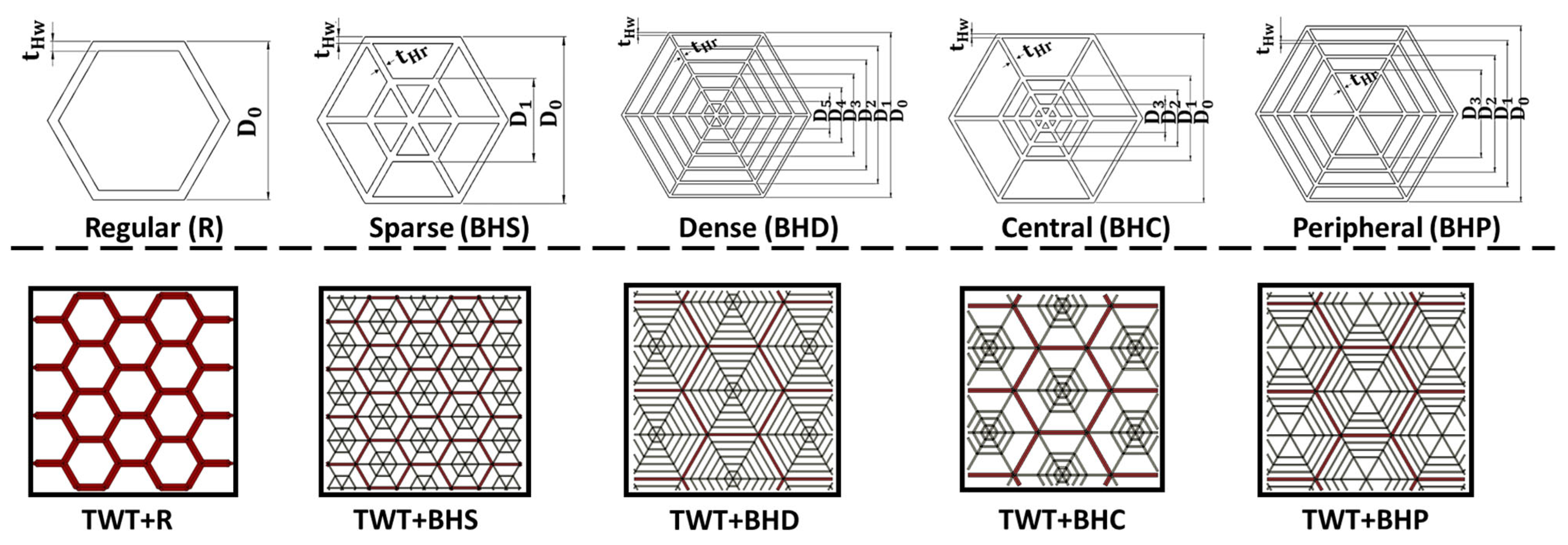
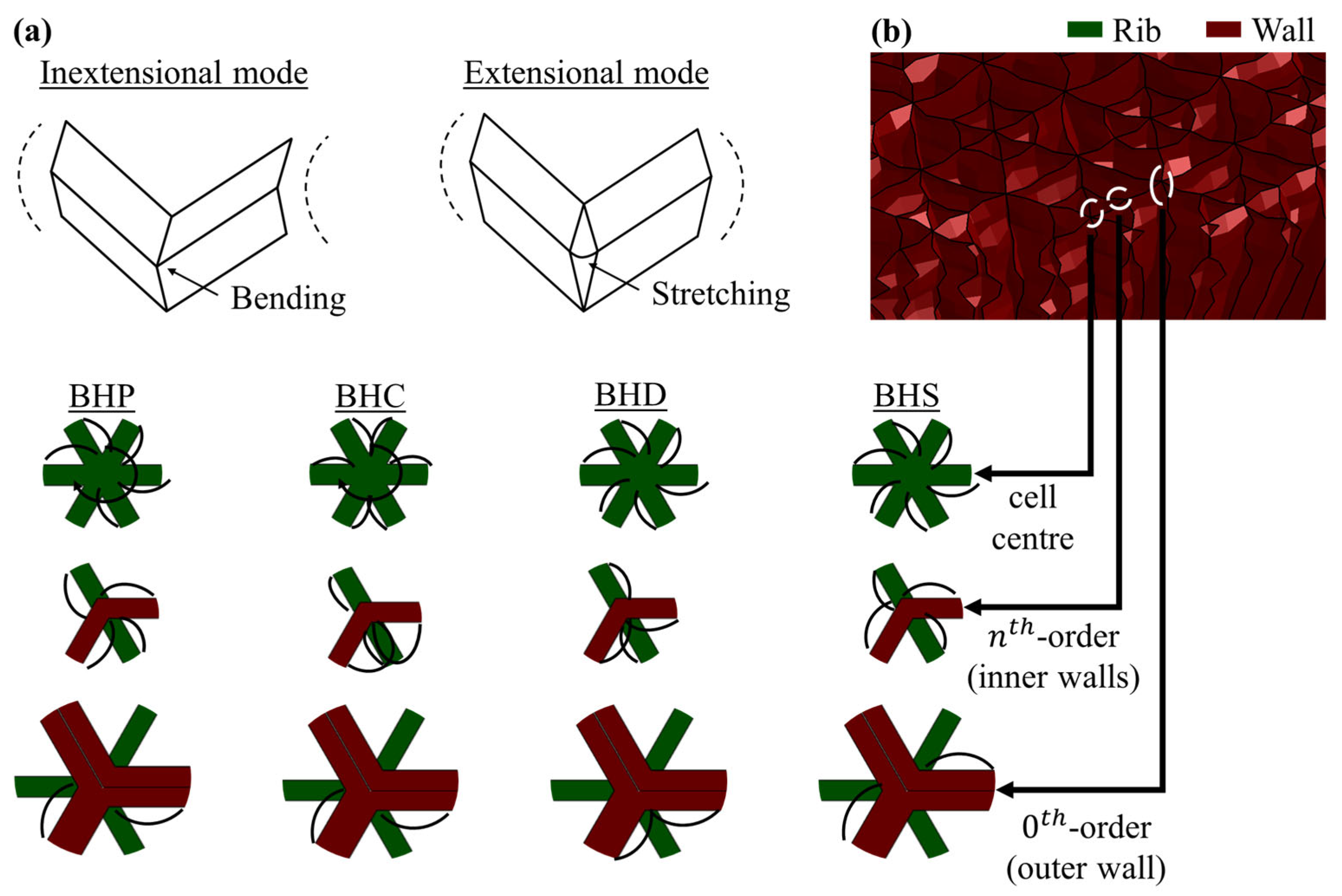
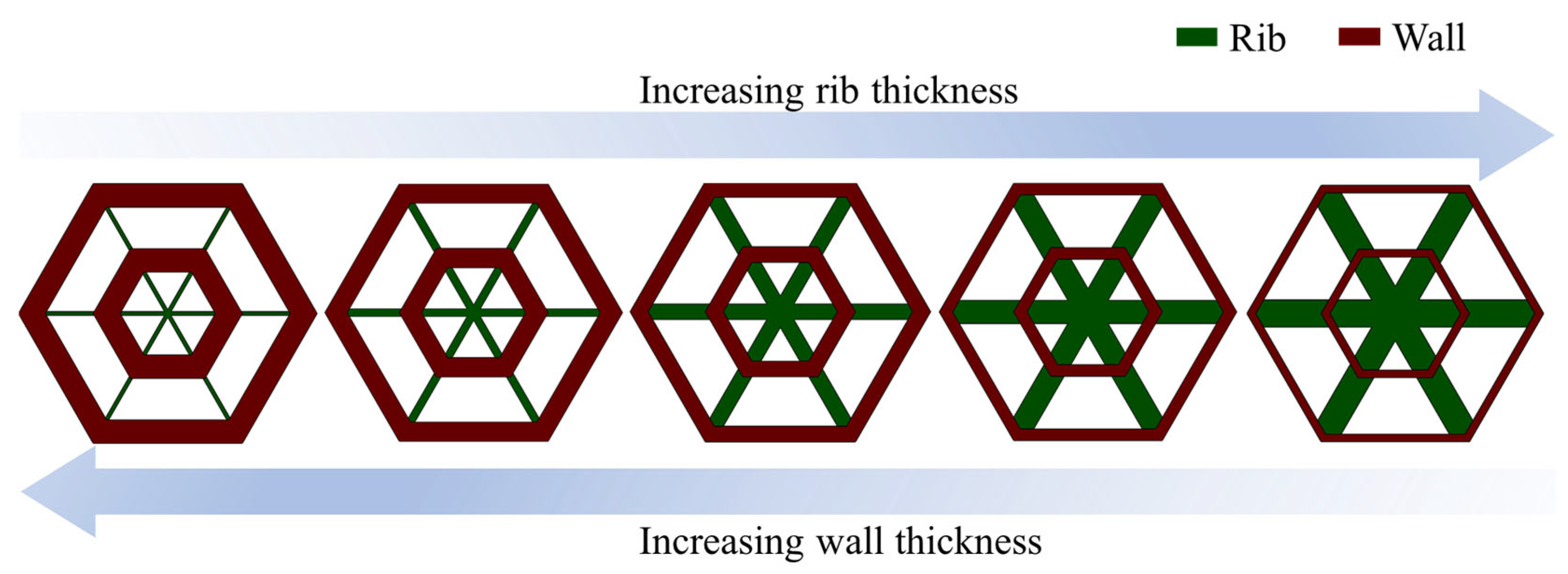
2.1. Design of Hierarchical Honeycomb-Filled Tubes

Four hierarchical honeycomb patterns inspired by the spider web, with variations in hierarchy distribution at their cellular levels, were considered in this study. The patterns were achieved by applying different levels of hierarchy at appropriate locations. As illustrated in Figure 1, the unit cell of a regular hexagonal honeycomb with a 0th-order hierarchy is described by its outer diameter D 0 and wall thickness t H w . A thin-walled tube (TWT) filled with this honeycomb pattern is named TWT+R. Similarly, the unit cells of the hierarchical honeycombs were derived by subsequently adding repeated hexagonal layers to the unit cell of a regular hexagon, where the geometry is described by the diameter of the hexagons D 0 to D 5 , the cell wall thickness t H w and the rib thickness t H r . The total number of added layers corresponds with the hierarchy order, and by adjusting the location of these layers, the four bio-inspired hierarchical patterns were assumed to be sparse (BHS), dense (BHD), central (BHC), and peripheral (BHP). Following this, thin-walled tubes (TWT) filled with these hierarchical honeycomb inserts are termed TWT+BHS, TWT+BHD, TWT+BHC and TWT+BHP, respectively. To avoid confusion, it is reiterated that the cellular topology and the hierarchical arrangement within the cells is referred to according to their corresponding names, i.e., sparse or BHS, dense or BHD, central or BHC and peripheral or BHP. The TWT term is appended to the cellular topology names when referring to the thin-walled tube with the honeycomb filler composite.
The edge length for the hollow inner space of the square tube measured 27.6   m m . Therefore, the side lengths of the fillers were made slightly smaller and measured 27   m m , for ease of insertion.
Based on the geometry of its cells, the total volume of the honeycomb block was derived. This method of derivation directly links the cell parameters to the range of volumes of the honeycomb blocks, and hence, the deformation behaviour of the housing thin-walled tube. The volume of a square honeycomb block as derived from its cellular geometry is written as follows:
V = 120 N c 2 n = 0 n 6 t H w 3 D 0 m n t H w + 6 t H r D 0 2 t H w 3
where V is the volume of the honeycomb block, N c presents the number of cells along an edge of a square cross-section, n is the hierarchy order, and m n is a dimensionless parameter relating the diameter of the outer hexagon D 0 to the diameter of the n th-order hexagon D n as m n = D 0 / D n . The first term of the equation within the bracket corresponds to the total volume occupied by the hexagons, while the second term corresponds to the total volume occupied by the connecting ribs. Naturally, the regular honeycomb would be devoid of the second term, as m n equates to 1 and t H r = 0 . A full derivation of the equation is provided in Appendix A. N C was derived from the cell diameter of the honeycomb hexagons and given as follows:
N c = 27 / D n
Since the next layer of reiterated hexagon formed within the previous layer, the expression for V is valid given that the following condition is satisfied:
D 0 > D 1 > D 2 > D n
t H r < D n 1 D n 2
Another important parameter, the rigidity ratio R g , provides a measurement for the stiffness of the honeycomb cells. As the unit cell of a regular honeycomb is characterised by a single hexagon, it has a single stiffness R g value, while for the hierarchical cells, R g is variable between a maximum and minimum value determined from the size of the largest and smallest hexagon, respectively. Therefore, the average value of R g was considered for hierarchical honeycomb unit cells. This dimensionless parameter is defined as follows:
R g = D n / t H w
The equation indicates that smaller unit cells with the same thickness have lower R g values. In other words, as R g increases, the stiffness of the unit cell decreases. The volumetric infill percentage V p which relates the volume of honeycomb cells ( V ) to the hollow space of tube ( V 0 ) is calculated as follows:
V p = V V 0 × 100 %
where V 0 = 27.6 × 27.6 × 120   m m . By keeping V p unchanged, the mass remains the same, and therefore, the parametric effect of different honeycomb cells can be compared. Although, it is important to note that an optimum range of V p exists where individual honeycomb cells can interact properly, both among each other and with the tube walls to enhance the energy absorption efficiency of the structure [20].
Table 1 lists the geometric dimensions of regular and hierarchical honeycomb cells contained within the thin-walled tubes. For a given level of V p , t H w and t H r are the same for all hierarchical and regular honeycomb cells. This ensures that the effect of thickness is mitigated, while only the hierarchical shape affects the performance of the tube. Note that, to maintain the same mass and V p , t H w and t H r were adjusted with an appropriate D 0 to D 5 as applicable for the specific cellular geometry of the honeycombs.

2.2. Crashworthiness Index

Four essential crashworthiness parameters are used to evaluate the performance of energy-absorbing structures. The total energy absorbed (TEA) by the structure is evaluated from the initiation of its compression to its complete collapse at the end of the plateau phase. It is calculated as follows:
T E A = 0 L d F d x
where L d is the total crush displacement until the densification phase, F is the instantaneous force and x is the crushed length.
Specific energy absorption (SEA) capability is a measure of a structure’s energy absorption efficiency per unit mass and is written as follows:
S E A = T E A M = 0 L d F d x M
where M represents the mass of the structure.
Initial peak force (IPF) corresponds to the first peak force in the force-displacement graph at the onset of the plateau phase of the structure. A large IPF is detrimental to safety.
Mean crushing force (MCF) measures the total energy absorbed per unit of crushed length of the structure. A lightweight compact structure with a high MCF has favourable crashworthiness.
M C F = T E A L d = 0 L d F d x L d
Crush force efficiency (CFE) is defined as the ratio of MCF to IPF and measures the force plateau effect of a structure. It is calculated as follows:
C F E = M C F I P F × 100 %
A higher CFE indicates efficient material participation in plastic deformation.

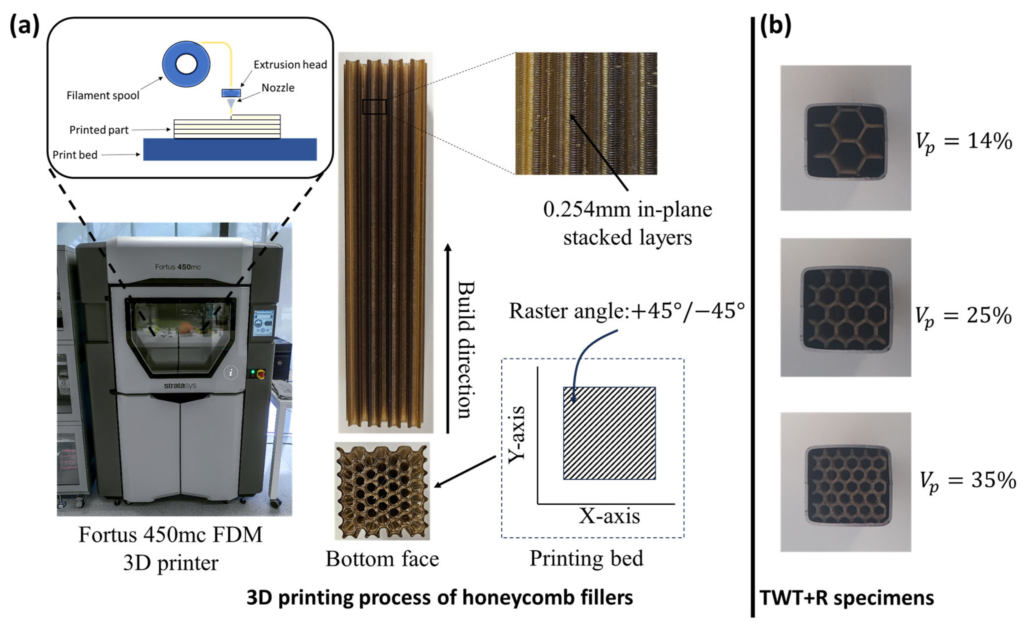
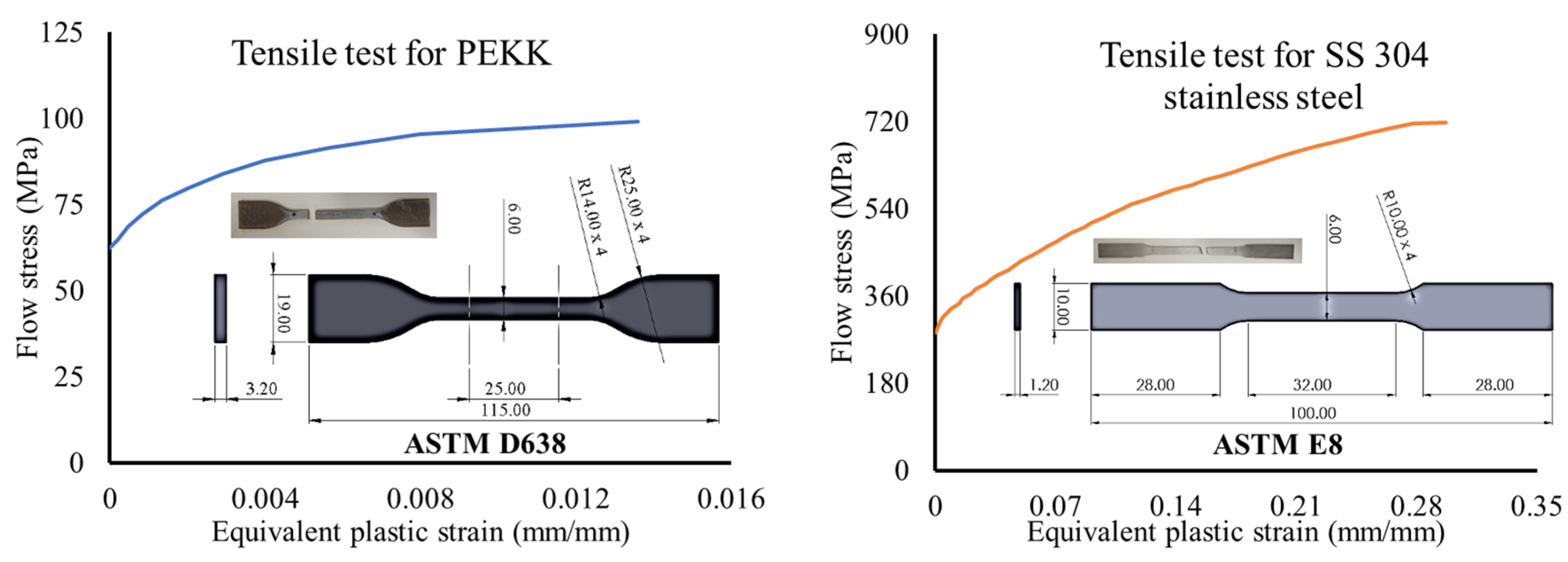
2.3. Materials and Specimens

The PEKK polymer has excellent strength and high rigidity due to the additional ether-ketone ring in its molecular chain. In this study, the PEKK filament “Antero 800NA” was considered for the honeycomb fillers. According to designed hierarchy patterns and filler volumes presented in Table 1, the fillers were modelled in CAD package software Solidworks 2021 SP05.1 and then the STL data were exported to the Fortus 450 mc 3D printer (Stratasys, Eden Prairie, MN, USA), as shown in Figure 2a. The industrial-grade fused deposition modelling (FDM) printer can print the most complex parts within an accuracy of ± 0.02   m m . As demonstrated in the schematics, the printing involved feeding the PEKK filament into the nozzle, which extruded the material as individual molten layers. The part was built as a flat (XY) orientation on the printing bed at a relative raster angle of + 45 ° / 45 ° . The temperature of the build chamber was maintained at 140 ° C to ensure a steady temperature gradient to minimise warping and crack growth within the printed part. The default layer height of 0.254 mm and 100 % solid infills were used for maximum anisotropic strength.
AISI 304 stainless steel (SS 304) was considered a suitable candidate for the thin-walled tube (TWT) due to its high strength, ductility, corrosion resistance, and inexpensiveness. Sheets of cold rolled SS 304 were cut into shape and welded together to fabricate the thin-walled tubes (TWTs) with dimensions of 30 × 30 × 120 mm3 and a thickness 1.2   m m . The printed TWT+R specimens (top view) are shown in Figure 2b.
Figure 3 shows the true post yield plastic material property with non-linear isotropic hardening for the PEKK polymer and SS 304 extracted from a series of dog-bone tensile tests conducted according to ASTM D638 [52] and ASTM E8 [53] standards respectively.. As noted from the snippets, both specimens failed within the gauge sections. These material data were imported to the Abaqus/Explicit solver and assigned to appropriate models for honeycomb and tube. The strength and deformation of the structures predominantly depend on the yield and ultimate strength of the materials. These properties are displayed in Table 2. Note that the PEKK polymer is relatively weak and ductile. However, this is advantageous in providing the appropriate cushioning effect and the lightweight high specific strength ratio to the housing thin-walled tube.

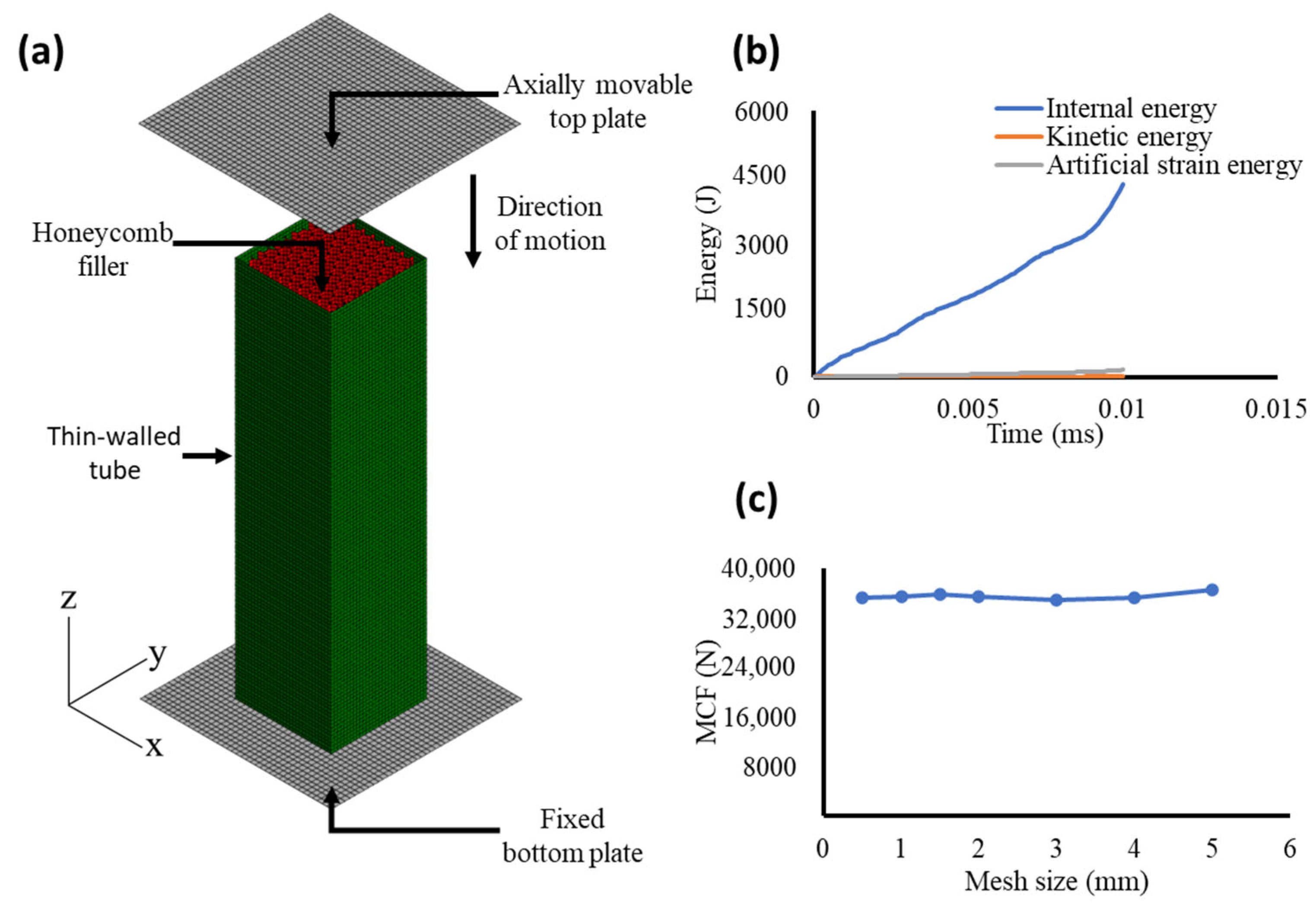
2.4. Numerical Modelling

In this study, the numerical models of the honeycomb-filled thin-walled tubes were developed using Abaqus/Explicit 6.25 with its powerful solver, which utilises an efficient iterative approach to tackle a wide array of highly non-linear plastic and complex deformation problems [42]. Four-node quadrilateral (S4R) shell elements with a reduced integration scheme were deployed to save computational efficiency. To counter the zero-energy artificial strain arising from this scheme, relaxed hourglass stiffness control was adopted [54].
Figure 4a depicts the representative numerical model of the honeycomb-filled thin-walled tube, placed unconstrained between a fixed bottom plate and a vertically movable top rigid plate in the out-of-plane direction. To avoid self-penetration and predict contact between surfaces with ease, a general contact algorithm with a friction coefficient of 0.2 between the honeycomb and tube was applied, while a relative sliding friction coefficient of 0.35 between the plates and tube/honeycomb was applied. This conservative selection of the friction coefficient considers the near frictionless sliding of PEKK against a smooth steel surface [55]. The quasi-static crush experiment was conducted at a slow rate of 5 mm/min. To replicate this in the simulation model, the crush rate was increased to 10 m/s, while the ratio of kinetic and artificial energy with the internal energy was maintained below 5% as shown in Figure 4b.
Imperfections affect the actual crushing behaviour of thin-walled tubes [56]. To simulate this effect, the first 10 buckling modes of the tube were calculated using linear buckling analysis and incorporated into the simulation model, with a maximum magnitude of no more that 2% of the tube’s thickness. This is important when the deformation mode is dominated by the tube. However, when the honeycomb fillers dominate the deformation at a higher V p , the effect of imperfection would become negligible.
Improved simulation accuracy comes at a higher computational cost when models are generated using very small elements. Therefore, mesh convergence analysis of the honeycomb-filled thin-walled tube was conducted by calculating the mean crush force (MCF) required to compress the tube against element size. As displayed in Figure 4c, a sharp convergence trend followed as the element size decreased, and plateaued below 1 mm. Therefore, to trade-off between the computational cost and prediction accuracy, the element size of 1 mm was selected for the analysis.

3. Results and Discussion

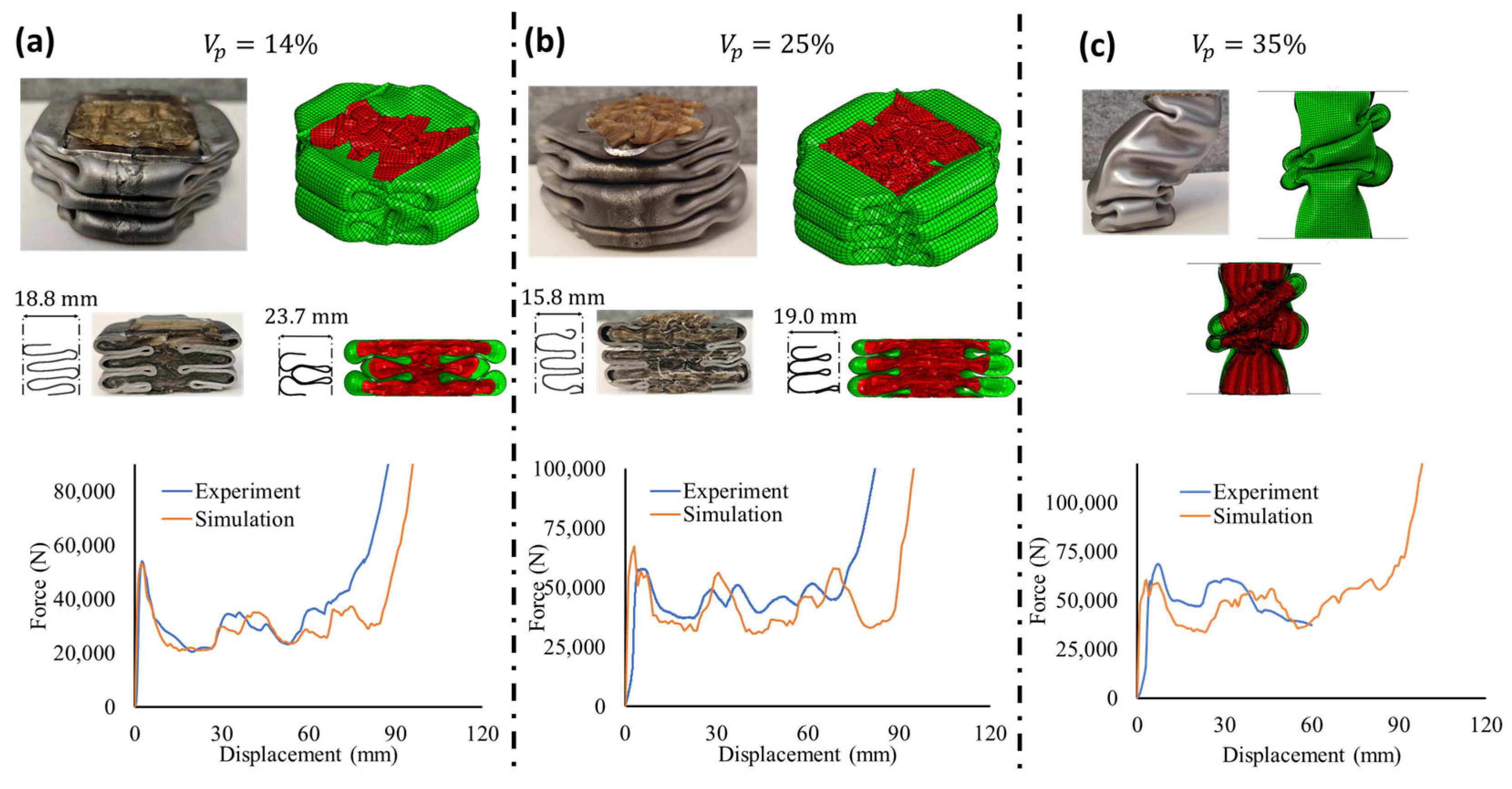
3.1. Crush Test and Numerical Validation

Due to the complexity in interaction between the honeycomb and fillers, three TWT+R specimens at V p = 14 % ,   25 %   a n d   35 % were subjected to quasi-static crush experiments as depicted in Figure 5.
Figure 5a represents that both the TWT+R specimen and its corresponding simulation model at V p = 14 % progressively deformed with 2~3 axisymmetric folds followed by densification. The cross-sections show the thin-film of honeycomb filler occupying the hollow space, which suggests that the volume occupied by the filler was too low to effectively participate in the energy absorption and that the deformation was dominated by the thin-walled tube. As observed from their respective force-displacement graphs, both experiment and simulation display good correlation in the overall trend until densification at approximately 70   m m of crush displacement. However, as the densification region does not correspond to the energy-absorbing features of thin-walled tubes, the discrepancy beyond this region, which is characterised by the spread of the local stiffness matrix due to the complex interaction of the filler walls, can be generally ignored [37].
Figure 5b reveals that increased cell density promoted a greater matching effect between the tube and honeycomb as the TWT+R specimen and corresponding numerical model at V p = 25 % were crushed with a greater number of folds. Their cross-section shows that the filler occupied additional space, which increased the lateral resistance and created thicker folds. Moreover, the force-displacement graph shows decent resemblance in size and location of peaks between the experiment and the simulation model.
Contrary to the previous experiments, progressive folding of TWT+R at V p = 35 % transitioned to global bending near the base of the tube, and the experiment had to be terminated, as illustrated in Figure 5c. It is evident that further increasing the cell density would be detrimental as the regular honeycomb filler has already surpassed its maximum performance limit. At this level of V p , the regular honeycomb cells had reached a rigidity ratio R g = 10 , compared to R g = 13 at V p = 25 % , which further contributed to the premature failure of the structure. According to the cross-section view, local asymmetric densification within the honeycomb cells were generated near the folds, and initiated bending moments, leading to the catastrophic failure. Irrespectively, for all cases, the simulation models remarkably captured the complex behaviour of the tubes to be considered for validation.

3.2. Deformation Analysis of Hierarchical Honeycomb-Filled Tubes

3.2.1. Deformation of TWT+BHS

Figure 6a depicts the progressive deformation of TWT+BHS under axial compression for 25 % V p 50 % . A quarter portion of the models have been removed for the clear illustration of the inside fillers. It is observed that increasing V p shifted the deformation mode of the tube from progressive a symmetric mode towards a more asymmetric mixed diamond mode, which was characterised by a rapid increase in the number of folds due to the continuous and symmetrical lateral penetration of the fillers. More importantly, unlike TWT+R, which failed in global bending mode at V p = 35 % , TWT+BHS maintained high stability followed by a greater energy absorption capacity up to V p = 50 % . As noted in Figure 6b, there was a dramatic improvement in the energy absorption capacity of TWT+BHS with V p , depicted by the constant upward shift in the area under the force-displacement graphs and the simultaneous reduction in corresponding force fluctuations. This cushioning effect at a higher V p is remarkably similar to that of foam-filled tubes.
To understand the bulk contribution of an individual hierarchical honeycomb cell on the deformation behaviour of a housing tube, Figure 6c illustrates the important transition phases of a unit cell for the BHS core at V p = 50 % , subjected to out-of-plane loading. It is noted that opposite walls shared similar behavioural trends of either stretching or compressing, while the connected ribs rotated to create an X-shaped pattern for the hierarchical unit cell, as it deformed axially. Moreover, according to the geometry of the cell, the out-of-plane load was shared among six load points (load points refer to the connecting members of a rib, i.e., four edges and two ribs) for each connecting rib, leading to its almost immediate local near-symmetric densification. While this deformation mechanism improved the plateau and energy absorption capacity, the short load-sharing branches for TWT+BHS created a stiffer response corresponding to R g = 25 ,   17   a n d   12 at V p = 25 % ,   40 %   a n d   50 % , respectively. As a drawback, IPF increased significantly.

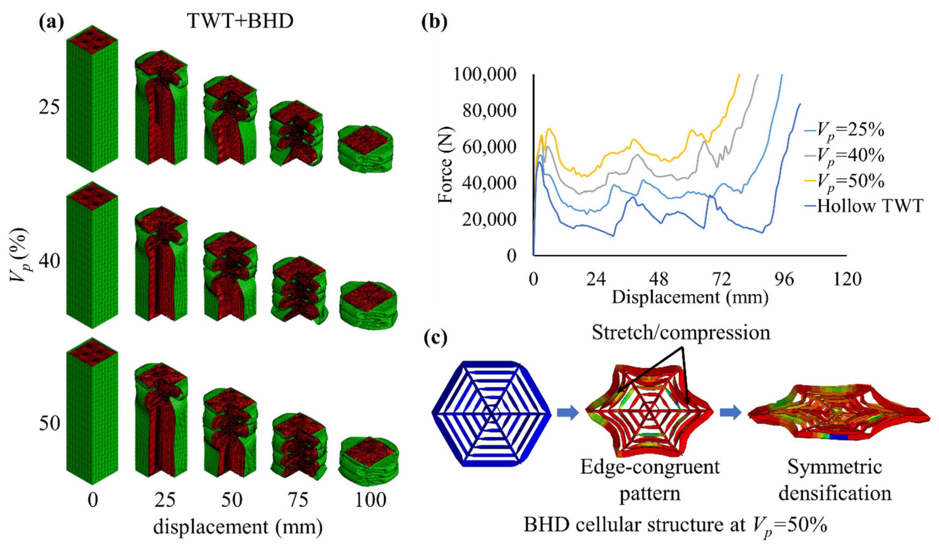
3.2.2. Deformation of TWT+BHD

TWT+BHD deformed in progressive symmetric mode akin to the hollow thin-walled tube at all levels of V p , as depicted in Figure 7a. As V p increased from 25% to 50%, the fillers smoothly spread within the hollow space of the folds without displaying any sign of instability. This indicates a favourable tube and filler wall-to-wall interaction and improved matching effect for this hierarchical pattern. Figure 7b confirms the similar deformation trend of TWT+BHD to the hollow TWT, characterised by peaks occurring at the same locations and the gradual early shift of densification with the increase in V p . Most importantly, contrary to the other hierarchical patterns, the IPF for TWT+BHD remained relatively unchanged, irrespective of V p . Moreover, the energy absorption capacity of the tube gradually improved with crushing displacement, as evident from the rising stress plateau region at all levels of V p . This type of deformation trend is similar to that of gradient honeycomb fillers.
Figure 7c demonstrates that the BHD cellular structure behaved with low stiffness and symmetry across its members when subjected to the out-of-plane compression loading. The edges deformed synchronously inward via stretching/compression, while the inner ribs remained virtually stationary and maintained cellular stability, leading to the edge-congruent dominated pattern. Note from Table 1 that although the BHD pattern had the highest order of hierarchy, the structure was relatively less stiff corresponding to R g = 35 ,   25   a n d   18 at V p = 25 % ,   40 %   a n d   50 % , respectively. It is possible that the increased number of load points (recall that the BHS pattern had six load points while the BHD pattern had 14 load points) effectively reduced the shared load among the connecting edges and ribs, leading to a lower increase in IPF, less rigid cellular deformation and less localised stress on the tube walls.

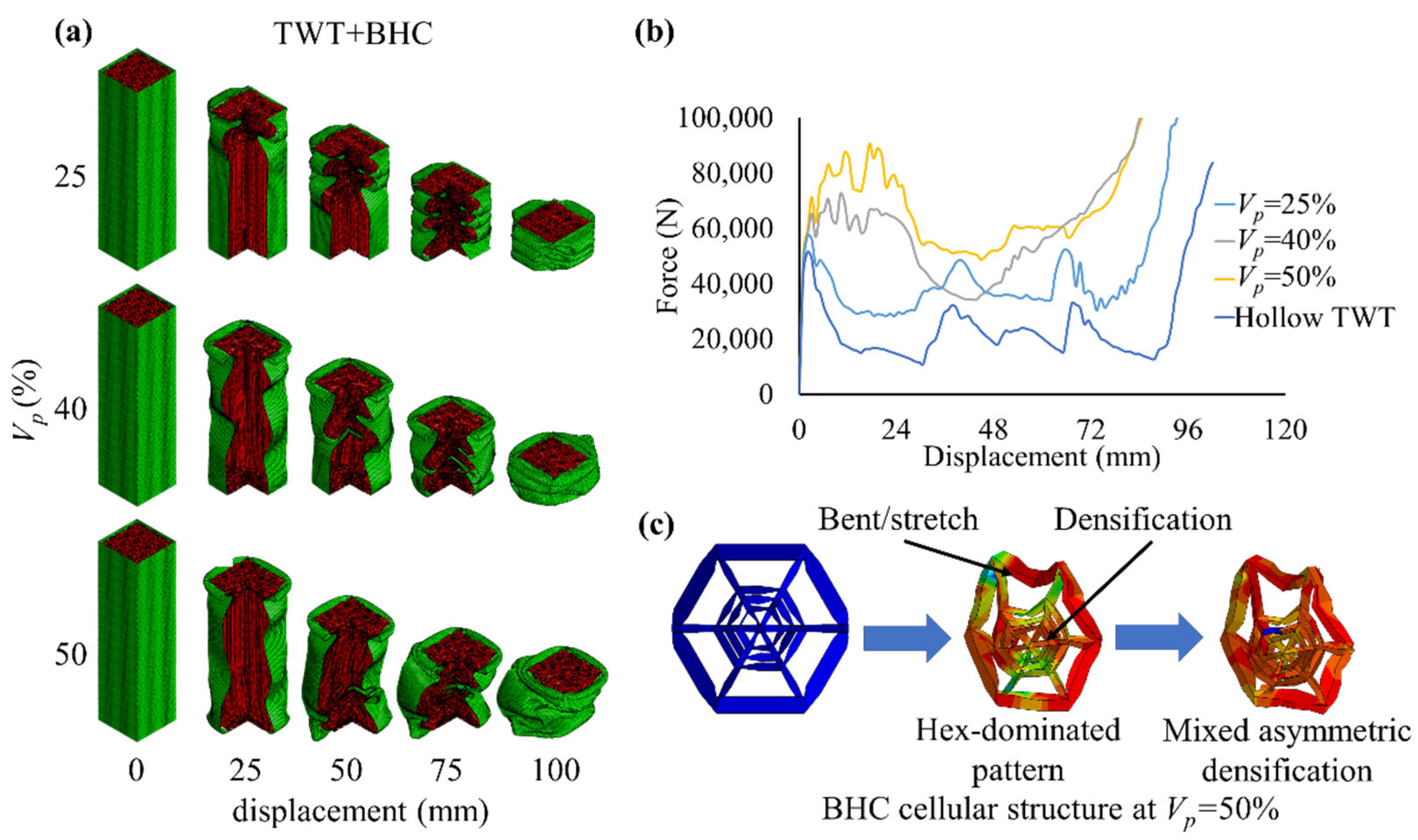
3.2.3. Deformation of TWT+BHC

Figure 8a reveals that TWT+BHC suffered a consistent decline in stability and energy absorption capacity as fillers dominated the deformation with the increase in V p . As V p gradually increased from 25% to 50%, the stiffer hierarchical honeycomb ( R g = 11   a t   V p = 50 % ) sustained global bending deformation. It is further illustrated in Figure 8b that the force displacement response of TWT+BHC at V p = 25 % was similar to that of hollow TWT, which implies that the deformation was dominated by the housing tube while the filler densification dissipated additional energy. However, beyond this V p range, the BHC pattern triggered an unfavourable response, leading to a drastic increase in IPF, followed by a significant decrease in energy absorption in the stress plateau phase.
While it is obvious that the TWT+BHC should be avoided as an energy-absorbing structure due to the instability, its cellular behaviour needed to be examined, as shown in Figure 8c. It is seen that the dense and relatively large distribution of the inner hierarchical hexagons inhibited their efficient folding and promoted the premature hex-dominated type of densification patterns of this localised region, while the outer hexagon still predominantly experienced bending coupled with some stretching response at the wall junctions. As a result, the deformation of the filler was governed by a mixed asymmetric densification stage and subsequently, this effect multiplied to the rest of the cells, creating a substantial bending moment at the weakest locations of the structure. Meanwhile, the dense load-sharing points at the rigid cell centres might have contributed to the rapid increase in IPF.

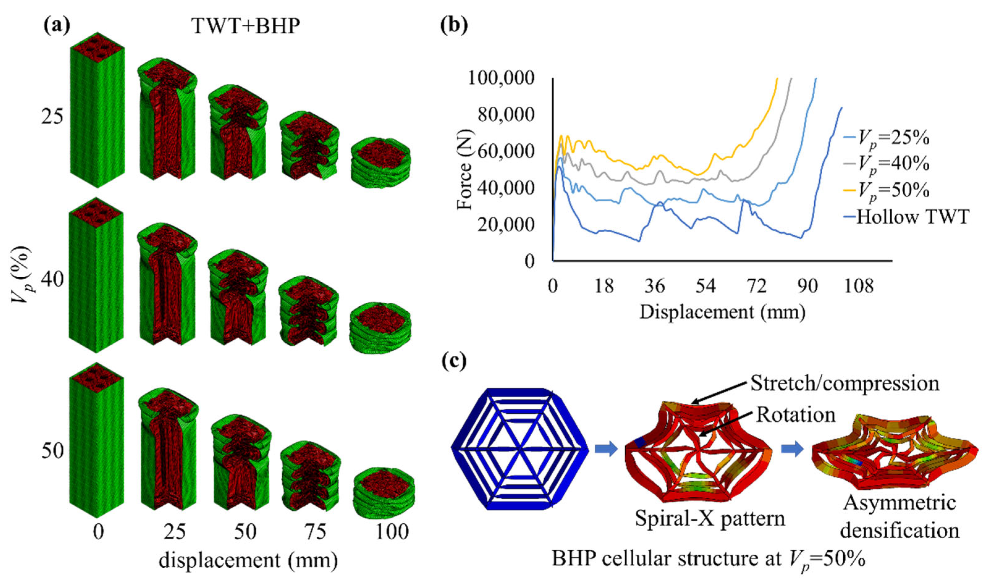
3.2.4. Deformation of TWT+BHP

Figure 9a displays that TWT+BHP sustained a stable deformation similar to that of TWT+BHD (refer to Figure 7a) at all levels of V p . Additionally, BHP fillers had an improved matching effect as the deformation mode changed from a progressive symmetric mode to a more efficient concertina mode at 25 V p 40 , characterised by an increased number of folds. As evident from Figure 9b, TWT+BHP improved the force plateau, governed by consistent flattening of the peaks with the increase in V p . One important thing to note is that contrary to BHS and BHC, the cushioning effect of both BHP and BHD demonstrated quite similar force trends, while simultaneously, both structures had relatively low stiffness (refer to Table 1 for R g ) at any given V p , which had a positive influence on IPF.
As illustrated in Figure 9c, the BHP cellular hierarchical pattern deformed in a spiral X pattern characterised by the stretching of the walls at its periphery and the rotation of the ribs into an X shape during out-of-plane loading. As the structure was slender, the load sustained by its individual walls and ribs was low, leading to reduced stiffness and gradual densification during deformation, similar to BHD cells. However, it is noted from Section 3.2.2 that the ribs of BHD cells did not contribute much to energy absorption, while the ribs of BHP cells rotated due to load sharing at the periphery and hence, contributed to energy absorption.

3.2.5. Deformation Modes of Hierarchical Honeycomb Cells

The topological effect of hierarchy on the deformation mechanics requires investigating the progressive crushing dynamics. The Gibson and Ashby model classifies slender cellular solids as deforming in bending- or stretching-dominated modes [57,58]. For hierarchical arrangement, a complex interaction between bending and stretching collaboratively govern the deformation kinematics and energy absorption of the honeycomb cells. To elaborate, the fold mechanics of the hierarchical cellular elements, i.e., the ribs and walls of each cellular topology, can be described as a plastic collapse of thin plates under axial loading [59]. The plates deform in inextensional and extensional modes in accordance with classical fold mechanics under axial loading, as illustrated in Figure 10a. The three-dimensional view in Figure 10b demonstrates the folding mechanism as triggered by the hierarchical topological arrangement. It is noted that for all hierarchy types (BHS, BHD, BHC and BHP), the hinge points at the outer wall and cell centre are identical, while the number and distribution of hinge points at the inner walls varies according to the hierarchical topology. It is observed for a BHS topology that energy is predominantly absorbed by stretching in an extensional mode at the walls while the ribs undergo axisymmetric inextensional bending for stability. An identical trend is observed for the BHD topology except stretching direction of cell walls is reversed. A different trend is observed for BHC topology as in this case, the outer wall undergoes inextensional bending while the inner walls and ribs undergo an extensional mode of deformation and pack together to form a solid whole. This mismatch triggers a rotation at the cell centre which may be the reason for the global bending mode of the honeycomb. Interestingly, although the BHP topology displays a inextensional deformation for both walls and tube and some rotation at the cell centre, it does not suffer from any global instability effect. From these observations, it can be inferred that besides the rigidity ratio, the extensional instability at inner walls of the hierarchy along with the mismatch in deformation mode at the outer wall primarily contributes to instability. In contrast, the structures are relatively stable when walls and ribs share similar deformation modes.

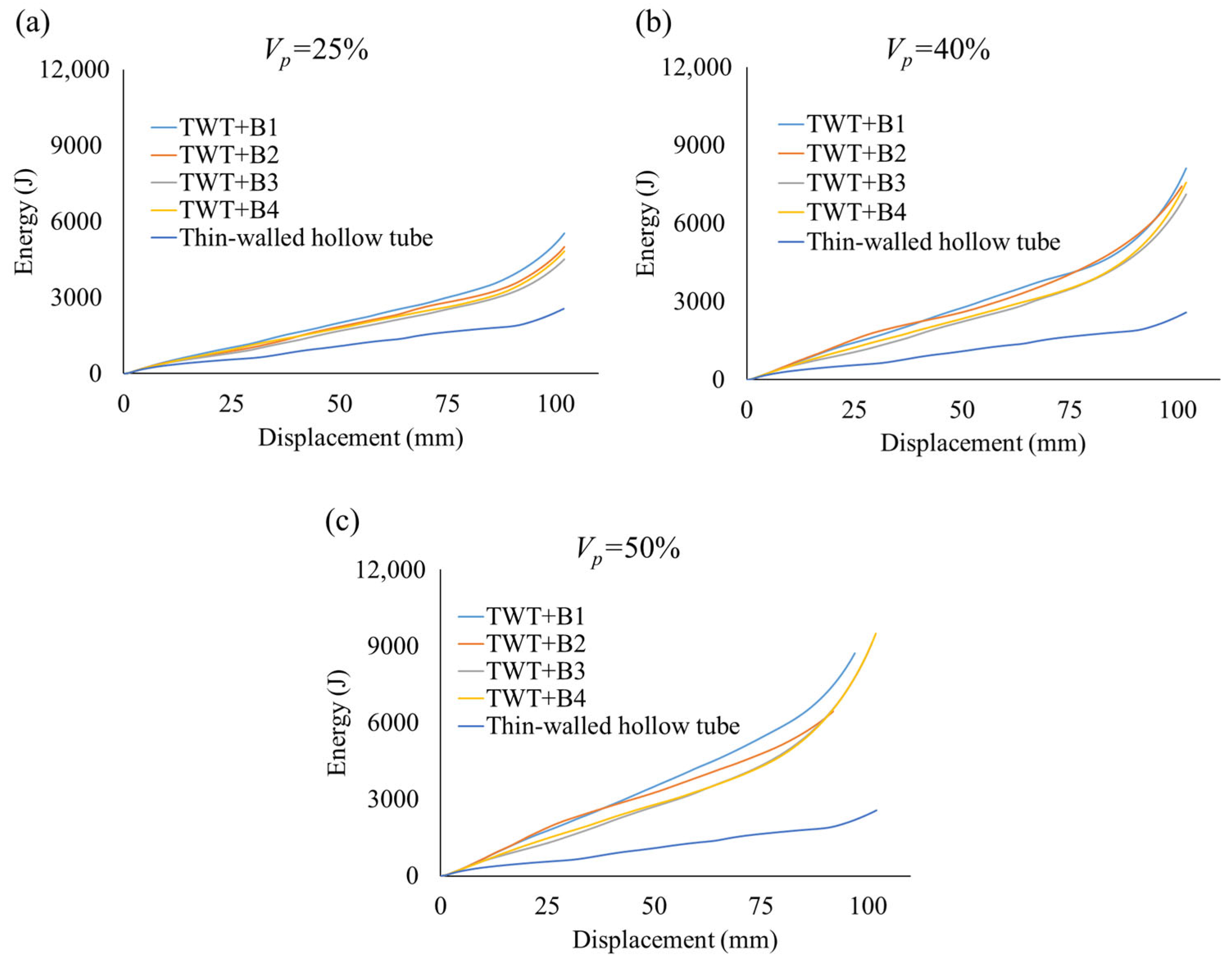
3.3. Crashworthiness Performance Analysis

Figure 11 compares the accumulated energy of the hierarchical honeycomb-filled tubes at 25 V p 50 against the hollow thin-walled tube. Each tube experienced a steady rate of energy absorption until densification. Moreover, the increased participation of the fillers with V p promoted higher rates of energy absorption over the thin-walled hollow tube. Figure 11a–c depict that, as TWT+BHS was compressed, it absorbed the highest level of energy with an increase in V p . In contrast, the energy absorption level of TWT+BHC was fluctuating and eventually declined at V p = 50 % , as it finally failed in global bending mode. TWT+BHD and TWT+BHP displayed relatively lower but consistent levels of energy irrespective of V p , suggesting a higher degree of stability for these tubes.
The crashworthiness of the proposed hierarchical honeycomb-filled thin-walled tubes against their cellular structural rigidity ratio R g is displayed in Figure 12 (recall that a higher R g corresponds to a lower stiffness of the cells). V p ranging from 25% to 50% (note that for the same V p , the mass is the same) is also included to illustrate the bulk effect of the honeycomb configuration on the crashworthiness and R g . The corresponding values are presented in Table 3 for reference.
It is observed from Figure 12a that as V p doubled from 25% to 50%, the structure of the TWT+BHS rapidly became rigid and sustained a drastic increase in SEA of 80%. When compared to the hollow tube, the increase was around 202.5%. Interestingly, both at V p = 40 % and 50%, TWT+BHS outperformed TWT+BHD and TWT+BHP. In stark contrast, TWT+BHC failed prematurely in global bending mode and scored the lowest SEA, although its cells had similar R g values to those of TWT+BHS at a corresponding V p . This indicates that TWT+BHS is more efficient at absorbing energy over the other composites. Among TWT+BHD and TWT+BHP, both composites delivered nearly identical SEA performance, although BHP cells were less rigid at a corresponding level of V p . As R g directly relates to cellular topology, this suggests that the peripheral distribution of hierarchy corresponding to BHP cells is structurally more efficient. Conversely, the dense composition of hierarchy for the BHD cellular topology was already saturated for further improvement in performance. In terms of V p , as it doubled from 25% to 50%, both composites demonstrated a gradual increase in SEA of approximately 40%, i.e., half as efficient as TWT+BHS.
According to Figure 12b, as V p increased from 25% to 50%, TWT+BHS showed an around 52% rapid rise in IPF. A similar trend and level of increase is observed for TWT+BHC, confirming that rigid cells with low R g values are unfavourable in terms of IPF. In contrast, the maximum increase in IPF for TWT+BHD and TWT+BHP was only approximately 12%, again confirming that cells with low stiffness are beneficial in keeping IPF low.
In terms of CFE, the performance of TWT+BHS initially improved with V p , but plateaued at V p = 50 % due to the steep increase in IPF, as shown in Figure 12c. As was further evidenced, TWT+BHD and TWT+BHP experienced a favourable and gradual increasing trend in CFE with V p due to a low increase in IPF. For the case of TWT+BHC, prior to its failure at V p = 50 % , its CFE was at a comparable level to those of the other tubes. This happened since the fillers still absorbed energy through local densification, which raised the MCF value. Therefore, it is suggested to always supplement the crashworthiness score with observed deformation behaviour of the tubes for accurate performance evaluation.
To summarise, TWT+BHS was superior in terms of energy absorption capacity and efficiency over the other tubes. This is related to the increased stiffness of its honeycomb cells, which is also responsible for significantly increasing the IPF. Therefore, some manner of control measure is required when incorporating thin-walled tubes with honeycomb fillers with a BHS cellular topology. The TWT+BHC composite should be avoided as its central hierarchical distribution of honeycomb cell topology triggered a global bending failure mode and delivered deteriorating crashworthiness performance. Both TWT+BHD and TWT+BHP demonstrated a moderate increase in SEA with V p . Furthermore, the reduced stiffness of their cells was beneficial in maintaining a low increase in IPF. Moreover, the BHP topology was structurally more efficient, while the dense hierarchy of the BHD cellular topology was already saturated for design improvement.

3.4. Effect of Honeycomb’s Ribs on Crashworthiness of TWT+BHS

Noting that the crashworthiness of the hierarchical honeycomb-filled thin-walled tubes is influenced by the cellular rigidity of the honeycomb, the high rise in IPF of TWT+BHS at V p = 50 % might be controlled by adjusting the cell geometry. One effective way to optimise both the SEA and the IPF could be varying the thickness of the connecting ribs, which so far was the same as the cell wall thickness, i.e., t H r = t H w . Therefore, four additional models were evaluated numerically with t H w = 0.60, 0.50, 0.30 and 0.20 mm and corresponding t H r = 0.10 ,   0.20 ,   0.60   a n d   0.70   m m , as shown in Figure 13. Note that as wall thickness decreased, the thickness of ribs increased to maintain the same mass at V p = 50 % .
Numerical analysis revealed that all the honeycomb-filled tubes failed progressively. The crashworthiness comparison in Table 4 illustrates that IPF can be efficiently managed by decreasing the thickness of the ribs. A decrease in t H r from 0.40 to 0.10 mm reduced the IPF by 15.5%. In comparison, the SEA decreased by 21.3%. As the ribs are important in load sharing, reducing their thickness inhibits the energy dissipation of the cell walls through progressive folds. Conversely, a reduction in t H w from 0.40 to 0.30 mm and a corresponding increase in t H r from 0.40 to 0.60 mm improved the energy absorption capacity while reducing IPF. The IPF reduced by 3.7%, while the SEA and CFE increased by 2.1% and 6.0%, respectively. As t H r was increased to 0.70 mm, IPF was further reduced along with SEA. This implies that there is a saturation point for t H r beyond which limited wall-to-wall interactions would plateau the SEA. Overall, the results indicate that both t H r and t H w influence the crashworthiness of TWT+BHS.

3.5. Structural Validation of Hierarchical Honeycomb-Filled Tube

Our numerical results have shown strong crashworthiness potential for the hierarchical honeycomb-filled thin-walled tubes, which failed progressively. Furthermore, TWT+BHS displayed the best energy absorption efficiency compared to the rest of the tubes. Therefore, a quasi-static crush test was conducted on three sets of a TWT+BHS specimen at V p = 50 % . The crush test report of each specimen was within one standard deviation of the set. However, it must be specified that our 3D printer was limited by its capability to print the thin walls of the cellular topology at V p = 50 % . To circumvent this challenge, the model was scaled, which had its dimensions of D 0 , D 1 , t H w and t H r scaled to 15 mm, 7.5 mm, 1 mm and 1 mm, respectively. The rest of the parameters were left unchanged to ensure that V p remained at 50%. The model’s geometry was carefully considered during scaling so that D 0 / t H w remained approximately the same. This would ensure that the cell walls have the same space in which to deform and densify during compression. Figure 14 depicts the specimen and corresponding numerical model, their crush status and force-displacement comparison. Note that R g = 45 for this specimen, which indicates that its unit cells have the lowest level of stiffness compared to the rest of the models studied in this paper. Overall, this specimen exhibited a progressive mixed mode of deformation along with some instability around the mid-location and reached densification at c d = 50   m m , as evident from the force-displacement graph. It can be inferred from this observation that there is a competition between wall thickness and r g to trigger dominating deformation modes. Regardless, the numerical model shows strong correlation with the experiment, displaying a similar deformation trend and force profile. The relaxed stiffness beyond the densification zone can be omitted. The difference in SEA, IPF and CFE results between the experiment and simulation were within 3.7%, 1.1% and 4.8%, respectively. This confirms with confidence that the numerical model developed in this study was accurate in predicting the crashworthiness of the proposed hierarchical honeycomb-filled tubes.

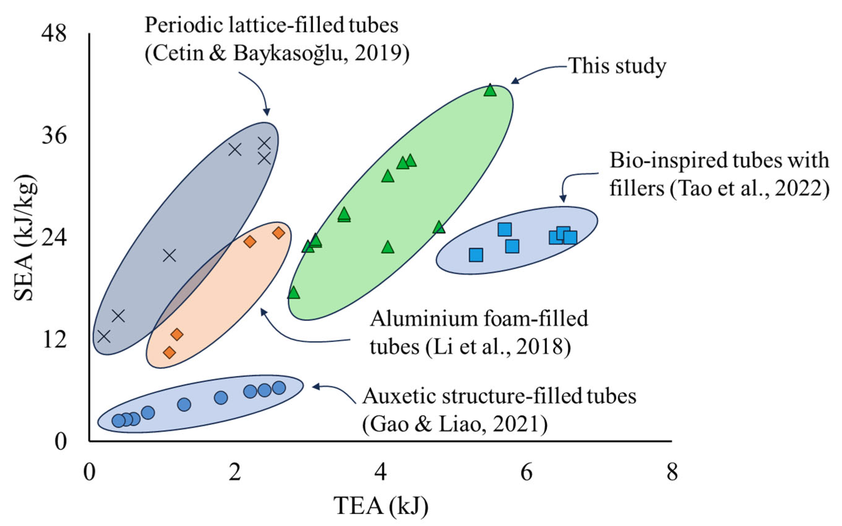
3.6. Crashworthiness Comparison with Existing Designs

To address the lightweight design and high energy dissipation capacity of thin-walled structures, the proposed hierarchical honeycomb-filled metallic thin-walled tubes were compared to existing filler-reinforced tubes of novel structural designs and material compositions. Among the selection criteria, SEA was considered since the novelty of the lightweight design can be directly correlated to energy absorption. Similarly, TEA would provide insight into the applicability of the design to real-world applications where high energy absorption is necessary. Figure 15 illustrates the Ashby graph, where the scattered data points correspond to the dominating regions for each design, as they relate energy dissipation with structural mass efficiency. Readers may refer to the corresponding references for the published data or calculate each of the parameters interchangeably with knowledge of structural mass. The bio-inspired tubes [23] were configured with honeycomb fillers at optimised locations to dissipate greater energy. The periodic lattice-filled tubes [60] utilised the BCC and BCC-Z lattices as fillers to enhance interaction with the housing tube. The auxetic structures [61] incorporated the double-arrowhead design to improve energy absorption and stability. Lightweight porous, foamy structures of aluminium foam-filled tubes [62] are advantageous for quick energy dissipation. From our study, the data points are approximately concentrated at the centre and observed to drift towards the upper right corner. This favourable performance suggests that PEKK as a high-strength polymer material for most hierarchical designs of the fillers was effective at elevating the mass efficiency, while the greater matching effect triggered the stable deformation of the housing tubes and improved the energy dissipation capacity. The results indicate that bio-inspired, hierarchical honeycomb-filled tubes have better competitiveness compared to other designs for the same level of energy absorbed. The tubes could find potential applications as high-functioning energy-absorbing structures to dampen crush impact.

4. Conclusions

The crashworthiness of four bio-inspired, reiterated hierarchical hexagonal-patterned honeycomb-filled thin-walled tubes were investigated in this study under out-of-plane compressive loading. Experimentally validated numerical results revealed that the honeycomb filler cell topology significantly influenced the deformation behaviour and crashworthiness performance of the tubes. The major findings and limitations of this study are outlined below.
  • The TWT+BHS composite, characterised by the sparse hierarchical distribution of its cellular topology, reached an impressive level of SEA against the hollow TWT of over 202%. Furthermore, the hierarchical topology of this composite was superior to that of the regular honeycomb, as it maintained stable deformation at V p = 50 % , while the latter failed at V p = 35 % . As V p doubled from 25% to 50%, it deformed in a symmetric X-shaped pattern and improved its SEA by 80%. Conversely, this pattern corresponded to the low rigidity ratio R g (high stiffness) of its honeycomb cells, which simultaneously increased its IPF by 52%. It is reiterated that, while a high SEA is crucial for maximising energy absorption during impact, a low IPF is equally critical to minimise occupant injury. Therefore, the multi-criteria crashworthiness indicators require careful consideration during modelling such complex structures.
  • Parametric analysis revealed that rib thickness t H r and cell wall thickness t H w affected the performance of the honeycomb-filled tubes. By increasing t H r to 0.6   m m and decreasing t H w to 0.3   m m , its IPF reduced by 3.7%, while SEA and CFE improved 2.1% and 6.0%, respectively. It can be inferred that fine tuning of these parameters can efficiently address the multi-criteria crashworthiness challenge.
  • The TWT+BHC composite, characterised by the central distributed hierarchy of its cellular topology, collapsed in the global bending mode as the cells densified in a hex-dominated pattern. Simultaneously, its IPF inclined sharply, corresponding to low R g . The unfavourable matching between the honeycomb core and thin-walled tube suggests that the TWT+BHC composite should be avoided in design consideration.
  • The TWT+BHD and TWT+BHP with respective dense and peripheral distributed cellular topologies collapsed in stable progressive modes, while their cells deformed in edge congruent and spiral X-pattern. As V p doubled from 25% to 50%, their SEA gradually elevated by approximately 40%. Their low cellular stiffness corresponding to a high R g limited the IPF increase to 12% at V p = 50 % . As a result, their CFE performance improved with V p . In particular, the ribs of BHP cells participated in energy absorption and hence, its structure was more efficient than the BHD cells.
  • As compared to existing honeycomb-filled tubes, the proposed hierarchical honeycomb-filled metallic tubes present as better contenders for crashworthiness improvement. The high-performance PEKK composition of the fillers was extremely effective at enhancing the energy turnover per increase in mass (SEA) while simultaneously increasing the total energy absorption capacity (TEA). However, it should be noted that while the hierarchical honeycomb is an attractive design choice for its superior energy absorption capability and light weight, its cellular geometry directly influences the deformation behaviour when used as a filler for thin-walled tubes. Therefore, careful design consideration is required.
  • While a scaled version of the hierarchical BHS honeycomb provides reasonable insight on the complex deformation pattern of the tube, the challenges associated with printing the original dimensions could be mitigated using more sophisticated manufacturing techniques such as Multi Jet Fusion (MJF) or Selective Laser Sintering (SLS). These technologies are tailored towards higher-dimensional accuracy, a better surface finish and improved mechanical performance. Similarly, the filler material can be replaced with metal alloys such as aluminium for low strength or titanium for high strength. These alternatives can be 3D printed with Electron Beam Melting or Laser Powder Bed Fusion which are optimised for producing sophisticated parts with exceptional quality and precision.
  • It is important to note that the current study presented in this thesis was limited to the quasi-static crush rate. However, it cannot be considered as a substitute for a dynamic crush study, which is more prevalent during an actual crush scenario. Additional factors, such as the strain rate sensitivity of the material and inertial conditions, could drastically change the deformation kinematics of the filled tube. Our future interest is investigating the effect of PEKK fillers on the dynamic plastic buckling deformation mode of thin-walled tubes, which can trigger a different crush response altogether.

Author Contributions

Conceptualization, methodology, validation, formal analysis, investigation, writing—original draft, data curation: S.A.; supervision, writing—review and editing: M.U. and C.H. All authors have read and agreed to the published version of the manuscript.

Funding

This research received no external funding.

Data Availability Statement

The original contributions presented in this study are included in the article. Further inquiries can be directed to the corresponding author.

Acknowledgments

This work used the NCRIS and Government of South Australia enabled Australian National Fab-rication Facility-South Australian Node (ANFF-SA). This research was undertaken with the assistance of resources from the National Computational Infrastructure (NCI Austral-ia), an NCRIS enabled capability supported by the Australian Government.

Conflicts of Interest

The authors declare no conflicts of interest.

Abbreviations

TWTThin-walled metal tubes
TWT+RThin-walled metal tube with regular honeycomb infill
SEASpecific energy absorption
TEATotal energy absorption
IPFInitial peak force
CFECrush force efficiency
BHSBio-inspired hierarchical sparse honeycomb
BHCBio-inspired hierarchical central honeycomb
BHDBio-inspired hierarchical dense honeycomb
BHPBio-inspired hierarchical peripheral honeycomb
TWT+BHS/BHC/BHD/BHPThin-walled metal tube with bio-inspired honeycomb infills
PEKKPolyetherketoneketone
PEEKPolyetheretherketone
CFCarbon fibre

Appendix A

Geometry of the honeycomb:
As shown in Figure A1, the area of the regular hexagon = total area of six equilateral triangles and is written as follows:
1 2 × 6 b × D 2
Figure A1. Unit cell of a regular hexagon.
Metals 15 00629 g0a1
The governing cosine relationship for a triangle is considered to find the edge length b in terms of the diameter of the governing circle. That means:
b = D 3
Substituting Equation (A1) into Equation (A2), the area of the hexagon becomes:
1 2 × 6 D 3 × D 2 = 3 D 2 2 3
To account for the cellular shape with the hollow interior region, the hexagon is offset by the governing thickness t H w   m m with the resulting diameter as:
D 2 = D 2 t H w
This gives the area of the offset hexagon as:
3 D 2 2 2 3 = 3 D 2 t H w 2 2 3
The difference between the area of the base and offset hexagon gives the area of a unit cell. Therefore:
3 D 2 2 3 3 D 2 t H w 2 2 3 = 6 t 3 ( D t H w )
For N c number of cells in a row, and height h   m m , the volume of the honeycomb becomes:
6 t H w h N c 2 3 ( D t H w )
The hierarchical pattern bio-inspired from a spider web is generated by replacing the hollow region of the regular honeycomb cells with smaller hexagons corresponding to the order of hierarchy and connecting ribs. The hierarchical order is denoted as n , where a zeroth order hierarchical honeycomb is generated when n = 0 and simply represents a regular honeycomb pattern with connecting ribs.
The geometry of a bio-inspired hexagonal unit cell is defined with the outer diameter of each layer and uniform thickness t H w . Correspondingly, inner layers can be represented as ratio of the outer diameter. Therefore, the area of the inner hexagon would become:
3 t H w 3 ( D 0 2 t H w )
Also, the length of each connecting rib is equal to the length of any given edge of the outer hexagon offset by the given thickness, and the total area is calculated as:
6 t H w ( D 0 2 t H w ) 3
Therefore, summing the area of outer hexagon, the area of the inner hexagon (the first level of hierarchy) and the area of the connecting ribs, the total area of the unit cell is calculated as:
6 t H w 3 D 0 t H w + 3 t H w 3 D 0 2 t H w + 6 t H r ( D 0 2 t H w ) 3
For the hierarchical honeycomb pattern with N c number of cells and height h   mm, the volume is expressed as:
h N c 2 ( 6 t H w 3 D 0 t H w + 3 t H w 3 D 0 2 t H w + 6 t H r ( D 0 2 t H w ) 3 )
The equation above can be extended to become a generic expression for any levels of hierarchy with respect to the outer honeycomb layer and given as follows:
h N c 2 [ n = 0 n 6 t H w 3 D 0 m n t H w + 6 t H r ( D 0 2 t H w ) 3 ]
N c is ratio of the edge length of the filler to the diameter of the outer hexagon of a unit cell, while m n denotes the diameter ratio of the outer honeycomb to the inner honeycomb for any given level of hierarchy. Both are expressed as:
N c = 27 / D 0 , given that the edge length of a filler is 27   m m .
m n = D 0 / D n
It should be noted that the defining diameter of the outer layer should be larger than the subsequent layer for a unit cell. Therefore:
D 0 > D 1 > D 2 > D n   and   t H w < D n 1 D n 2
The actual model has sections of cells at the edges of the honeycomb filler that are not accounted for in the equation and lead to underestimation. However, for accurate estimation, the margin of error lies within 5% for any size and thickness of honeycomb considered. The equation is iteratively solved using MATLAB 24.1.0.

References

  1. Abramowicz, W.; Jones, N. Dynamic progressive buckling of circular and square tubes. Int. J. Impact Eng. 1986, 4, 243–270. [Google Scholar] [CrossRef]
  2. Abramowicz, W.; Jones, N. Transition from initial global bending to progressive buckling of tubes loaded statically and dynamically. Int. J. Impact Eng. 1997, 19, 415–437. [Google Scholar] [CrossRef]
  3. Jones, N. Recent Studies on the Dynamic Plastic Behavior of Structures. Appl. Mech. Rev. 1989, 42, 95–115. [Google Scholar] [CrossRef]
  4. Karagiozova, D.; Jones, N. Dynamic elastic–plastic buckling of circular cylindrical shells under axial Impact. Int. J. Solids Struct. 2000, 37, 2005–2034. [Google Scholar] [CrossRef]
  5. Karagiozova, D.; Jones, N. Dynamic buckling of elastic–plastic square tubes under axial impact—II: Structural response. Int. J. Impact Eng. 2004, 30, 167–192. [Google Scholar] [CrossRef]
  6. Wierzbicki, T.; Abramowicz, W. On the Crushing Mechanics of Thin-Walled Structures. J. Appl. Mech. 1983, 50, 727–734. [Google Scholar] [CrossRef]
  7. Hayduk, R.J.; Wierzbicki, T. Extensional collapse modes of structural members. Comput. Struct. 1984, 18, 447–458. [Google Scholar] [CrossRef]
  8. Abramowicz, W.; Jones, N. Dynamic axial crushing of square tubes. Int. J. Impact Eng. 1984, 2, 179–208. [Google Scholar] [CrossRef]
  9. Sun, G.; Pang, T.; Xu, C.; Zheng, G.; Song, J. Energy absorption mechanics for variable thickness thin-walled structures. Thin-Walled Struct. 2017, 118, 214–228. [Google Scholar] [CrossRef]
  10. Nia, A.A.; Parsapour, M. Comparative analysis of energy absorption capacity of simple and multi-cell thin-walled tubes with triangular, square, hexagonal and octagonal sections. Thin-Walled Struct. 2014, 74, 155–165. [Google Scholar] [CrossRef]
  11. Wu, S.; Zheng, G.; Sun, G.; Liu, Q.; Li, G.; Li, Q. On design of multi-cell thin-wall structures for crashworthiness. Int. J. Impact Eng. 2016, 88, 102–117. [Google Scholar] [CrossRef]
  12. Altin, M.; Kılınçkaya, Ü.; Acar, E.; Güler, M.A. Investigation of combined effects of cross section, taper angle and cell structure on crashworthiness of multi-cell thin-walled tubes. Int. J. Crashworthiness 2019, 24, 121–136. [Google Scholar] [CrossRef]
  13. Patel, V.; Tiwari, G.; Dumpala, R. Crashworthiness analysis of multi-configuration thin walled co-axial frusta tube structures under quasi-static loading. Thin-Walled Struct. 2020, 154, 106872. [Google Scholar] [CrossRef]
  14. Vinayagar, K.; Kumar, A.S. Crashworthiness analysis of double section bi-tubular thin-walled structures. Thin-Walled Struct. 2017, 112, 184–193. [Google Scholar] [CrossRef]
  15. Yang, X.; Ma, J.; Sun, Y.; Yang, J. An internally nested circular-elliptical tube system for energy absorption. Thin-Walled Struct. 2019, 139, 281–293. [Google Scholar] [CrossRef]
  16. Baroutaji, A.; Sajjia, M.; Olabi, A.-G. On the crashworthiness performance of thin-walled energy absorbers: Recent advances and future developments. Thin-Walled Struct. 2017, 118, 137–163. [Google Scholar] [CrossRef]
  17. Wang, Z. Recent advances in novel metallic honeycomb structure. Compos. Part B Eng. 2019, 166, 731–741. [Google Scholar] [CrossRef]
  18. Thomas, T.; Tiwari, G. Crushing behavior of honeycomb structure: A review. Int. J. Crashworthiness 2019, 24, 555–579. [Google Scholar] [CrossRef]
  19. Hussein, R.D.; Ruan, D.; Lu, G.; Guillow, S.; Yoon, J.W. Crushing response of square aluminium tubes filled with polyurethane foam and aluminium honeycomb. Thin-Walled Struct. 2017, 110, 140–154. [Google Scholar] [CrossRef]
  20. Wang, Z.; Yao, S.; Lu, Z.; Hui, D.; Feo, L. Matching effect of honeycomb-filled thin-walled square tube—Experiment and simulation. Compos. Struct. 2016, 157, 494–505. [Google Scholar] [CrossRef]
  21. Zhang, Y.; Xu, X.; Lu, M.; Hu, Z.; Ge, P. Enhance crashworthiness of composite structures using gradient honeycomb material. Int. J. Crashworthiness 2018, 23, 569–580. [Google Scholar] [CrossRef]
  22. Zhu, G.; Li, S.; Sun, G.; Li, G.; Li, Q. On design of graded honeycomb filler and tubal wall thickness for multiple load cases. Thin-Walled Struct. 2016, 109, 377–389. [Google Scholar] [CrossRef]
  23. Tao, Y.; Wang, Y.; He, Q.; Xu, D.; Li, L. Comparative Study and Multi-Objective Crashworthiness Optimization Design of Foam and Honeycomb-Filled Novel Aluminum Thin-Walled Tubes. Metals 2022, 12, 2163. [Google Scholar] [CrossRef]
  24. Xie, S.; Wang, H.; Yang, C.; Zhou, H.; Feng, Z. Mechanical properties of combined structures of stacked multilayer Nomex® honeycombs. Thin-Walled Struct. 2020, 151, 106729. [Google Scholar] [CrossRef]
  25. Liu, Y.; Luo, D.; Wang, T. Hierarchical Structures of Bone and Bioinspired Bone Tissue Engineering. Small 2016, 12, 4611–4632. [Google Scholar] [CrossRef]
  26. Reznikov, N.; Bilton, M.; Lari, L.; Stevens, M.M.; Kröger, R. Fractal-like hierarchical organization of bone begins at the nanoscale. Science 2018, 360, eaao2189. [Google Scholar] [CrossRef]
  27. Tsang, H.H.; Raza, S. Impact energy absorption of bio-inspired tubular sections with structural hierarchy. Compos. Struct. 2018, 195, 199–210. [Google Scholar] [CrossRef]
  28. Wang, X.; Fang, J.; Zhu, W.; Zhong, C.; Ye, D.; Zhu, M.; Lu, X.; Zhao, Y.; Ren, F. Bioinspired Highly Anisotropic, Ultrastrong and Stiff, and Osteoconductive Mineralized Wood Hydrogel Composites for Bone Repair. Adv. Funct. Mater. 2021, 31, 2010068. [Google Scholar] [CrossRef]
  29. Ajdari, A.; Jahromi, B.H.; Papadopoulos, J.; Nayeb-Hashemi, H.; Vaziri, A. Hierarchical honeycombs with tailorable properties. Int. J. Solids Struct. 2012, 49, 1413–1419. [Google Scholar] [CrossRef]
  30. Wang, Z.; Li, Z.; Shi, C.; Zhou, W. Theoretical and numerical analysis of the folding mechanism of vertex-based hierarchical honeycomb structure. Mech. Adv. Mater. Struct. 2020, 27, 789–799. [Google Scholar] [CrossRef]
  31. Yin, H.; Huang, X.; Scarpa, F.; Wen, G.; Chen, Y.; Zhang, C. In-plane crashworthiness of bio-inspired hierarchical honeycombs. Compos. Struct. 2018, 192, 516–527. [Google Scholar] [CrossRef]
  32. Zhan, C.; Li, M.; McCoy, R.; Zhao, L.; Lu, W. 3D printed hierarchical re-entrant honeycombs: Enhanced mechanical properties and the underlying deformation mechanisms. Compos. Struct. 2022, 290, 115550. [Google Scholar] [CrossRef]
  33. Gosline, J.M.; DeMont, M.E.; Denny, M.W. The structure and properties of spider silk. Endeavour 1986, 10, 37–43. [Google Scholar] [CrossRef]
  34. Ko, F.K.; Jovicic, J. Modeling of Mechanical Properties and Structural Design of Spider Web. Biomacromolecules 2004, 5, 780–785. [Google Scholar] [CrossRef] [PubMed]
  35. Mousanezhad, D.; Ebrahimi, H.; Haghpanah, B.; Ghosh, R.; Ajdari, A.; Hamouda, A.M.S.; Vaziri, A. Spiderweb honeycombs. Int. J. Solids Struct. 2015, 66, 218–227. [Google Scholar] [CrossRef]
  36. He, Q.; Feng, J.; Chen, Y.; Zhou, H. Mechanical properties of spider-web hierarchical honeycombs subjected to out-of-plane impact loading. J. Sandw. Struct. Mater. 2020, 22, 771–796. [Google Scholar] [CrossRef]
  37. Wang, Z.; Zhang, J.; Li, Z.; Shi, C. On the crashworthiness of bio-inspired hexagonal prismatic tubes under axial compression. Int. J. Mech. Sci. 2020, 186, 105893. [Google Scholar] [CrossRef]
  38. Akman, A.; Sadhu, A. Recent Development of 3D-Printing Technology in Construction Engineering. Pract. Period. Struct. Des. Constr. 2024, 29, 03123005. [Google Scholar] [CrossRef]
  39. Ford, S.; Despeisse, M. Additive manufacturing and sustainability: An exploratory study of the advantages and challenges. J. Clean. Prod. 2016, 137, 1573–1587. [Google Scholar] [CrossRef]
  40. Nian, Y.; Wan, S.; Li, M.; Su, Q. Crashworthiness design of self-similar graded honeycomb-filled composite circular structures. Constr. Build. Mater. 2020, 233, 117344. [Google Scholar] [CrossRef]
  41. Zhang, X.G.; Jiang, W.; Zhang, Y.; Luo, C.; Zhang, X.Y.; Han, D.; Hao, J.; Teng, X.C.; Xie, Y.M.; Ren, X. Energy absorption properties of composite tubes with hexagonal and re-entrant honeycomb fillers. Constr. Build. Mater. 2022, 356, 129298. [Google Scholar] [CrossRef]
  42. Alkhatib, S.E.; Matar, M.S.; Tarlochan, F.; Laban, O.; Mohamed, A.S.; Alqwasmi, N. Deformation modes and crashworthiness energy absorption of sinusoidally corrugated tubes manufactured by direct metal laser sintering. Eng. Struct. 2019, 201, 109838. [Google Scholar] [CrossRef]
  43. Hussein, R.D.; Ruan, D.; Lu, G.; Sbarski, I. Axial crushing behaviour of honeycomb-filled square carbon fibre reinforced plastic (CFRP) tubes. Compos. Struct. 2016, 140, 166–179. [Google Scholar] [CrossRef]
  44. Sun, G.; Li, S.; Liu, Q.; Li, G.; Li, Q. Experimental study on crashworthiness of empty/aluminum foam/honeycomb-filled CFRP tubes. Compos. Struct. 2016, 152, 969–993. [Google Scholar] [CrossRef]
  45. Nassir, N.A.; Birch, R.S.; Cantwell, W.J.; Guan, Z.W. The response of glass fibre reinforced PEKK laminates subjected to single and multiple impact loading. Polym. Test. 2024, 131, 108323. [Google Scholar] [CrossRef]
  46. Derisi, B.; Hoa, S.V.; Xu, D.; Hojjati, M.; Fews, R. Mechanical Behavior of Carbon/PEKK Thermoplastic Composite Tube Under Bending Load. J. Thermoplast. Compos. Mater. 2011, 24, 29–49. [Google Scholar] [CrossRef]
  47. Wiese, M.; Thiede, S.; Herrmann, C. Rapid manufacturing of automotive polymer series parts: A systematic review of processes, materials and challenges. Addit. Manuf. 2020, 36, 101582. [Google Scholar] [CrossRef]
  48. Chattaraj, S.; Basu, S. Coarse-graining strategies for predicting properties of closely related polymer architectures: A case study of PEEK and PEKK. J. Mater. Res. 2022, 37, 1–12. [Google Scholar] [CrossRef]
  49. Nachtane, M.; Tarfaoui, M.; Ledoux, Y.; Khammassi, S.; Leneveu, E.; Pelleter, J. Experimental investigation on the dynamic behavior of 3D printed CF-PEKK composite under cyclic uniaxial compression. Compos. Struct. 2020, 247, 112474. [Google Scholar] [CrossRef]
  50. Andrew, J.J.; Alhashmi, H.; Schiffer, A.; Kumar, S.; Deshpande, V.S. Energy absorption and self-sensing performance of 3D printed CF/PEEK cellular composites. Mater. Des. 2021, 208, 109863. [Google Scholar] [CrossRef]
  51. He, P.; Wang, S.; Zhang, M.; Sang, L.; Tong, L.; Hou, W. Compression performance of 3D-printed thermoplastic auxetic structures. Thin-Walled Struct. 2024, 197, 111558. [Google Scholar] [CrossRef]
  52. ASTM D638-14; D20 Committee, Test Method for Tensile Properties of Plastics. ASTM: West Conshohocken, PA, USA, 2022. [CrossRef]
  53. ASTM E8/E8M-22; E28 Committee, Test Methods for Tension Testing of Metallic Materials. ASTM: West Conshohocken, PA, USA, 2022. [CrossRef]
  54. Lin, X.; Zhang, Y.X.; Pathak, P. Nonlinear Finite Element Analysis of Composite and Reinforced Concrete Beams; Elsevier: Amsterdam, The Netherlands, 2020. [Google Scholar] [CrossRef]
  55. Yahiaoui, M.; Chabert, F.; Paris, J.-Y.; Nassiet, V.; Denape, J. Friction, acoustic emission, and wear mechanisms of a PEKK polymer. Tribol. Int. 2019, 132, 154–164. [Google Scholar] [CrossRef]
  56. Hu, Y.; Rong, B.; Zhang, R.; Zhang, Y.; Zhang, S. Study of buckling behavior for 7A04-T6 aluminum alloy rectangular hollow columns. Thin-Walled Struct. 2021, 169, 108410. [Google Scholar] [CrossRef]
  57. Gibson, L.J.; Ashby, M.F. Cellular Solids: Structure and Properties, 2nd ed.; Cambridge University Press: Cambridge, UK, 1997. [Google Scholar] [CrossRef]
  58. Zhong, H.; Song, T.; Li, C.; Das, R.; Gu, J.; Qian, M. The Gibson-Ashby model for additively manufactured metal lattice materials: Its theoretical basis, limitations and new insights from remedies. Curr. Opin. Solid State Mater. Sci. 2023, 27, 101081. [Google Scholar] [CrossRef]
  59. Yang, Y.; Liu, H.; Zhang, Q.; Ma, J.; Yang, X.; Yang, J. Energy absorption characteristics of a super hexagonal honeycomb under out-of-plane crushing. Thin-Walled Struct. 2023, 189, 110914. [Google Scholar] [CrossRef]
  60. Cetin, E.; Baykasoğlu, C. Energy absorption of thin-walled tubes enhanced by lattice structures. Int. J. Mech. Sci. 2019, 157–158, 471–484. [Google Scholar] [CrossRef]
  61. Gao, Q.; Liao, W.-H. Energy absorption of thin walled tube filled with gradient auxetic structures-theory and simulation. Int. J. Mech. Sci. 2021, 201, 106475. [Google Scholar] [CrossRef]
  62. Li, Z.; Chen, R.; Lu, F. Comparative analysis of crashworthiness of empty and foam-filled thin-walled tubes. Thin-Walled Struct. 2018, 124, 343–349. [Google Scholar] [CrossRef]
Figure 1. (Top, from left to right) Unit cell geometry for a regular hexagon and bio-inspired hierarchical hexagons with sparse, dense, central and peripheral distributions; (Bottom, from left to right) the corresponding honeycomb-filled thin-walled tubes.
Metals 15 00629 g001
Figure 2. (a) Fortus 450 mc FDM 3D printer and schematics showing the printing of honeycomb filler; (b) TWT+R specimens at V p = 14 % ,   25 %   a n d   35 % .
Metals 15 00629 g002
Figure 3. True material properties for PEKK and SS 304 based on dog-bone tensile tests conducted according to ASTM D638 (left) and ASTM E8 (right), respectively.
Metals 15 00629 g003
Figure 4. (a) Numerical model for honeycomb-filled thin-walled tube; (b) energy performance comparison; (c) Mesh convergence analysis.
Metals 15 00629 g004
Figure 5. Quasi-static crush test and cross-sectional deformation folding of the TWT+R specimens and corresponding simulation models at (a) V p = 14 % , (b) V p = 25 % and (c) V p = 35 % .
Metals 15 00629 g005
Figure 6. (a) Deformation sequence of TWT+BHS at V p = 25 % ,   50 %   a n d   50 % , (b) corresponding force-displacement graph and (c) cellular behaviour.
Metals 15 00629 g006
Figure 7. (a) Deformation sequence of TWT+BHD at V p = 25 % ,   50 %   a n d   50 % , (b) corresponding force-displacement graph and (c) cellular behaviour.
Metals 15 00629 g007
Figure 8. (a) Deformation sequence of TWT+BHC at V p = 25 % ,   40 %   a n d   50 % , (b) corresponding force-displacement graph and (c) cellular behaviour.
Metals 15 00629 g008
Figure 9. (a) Deformation sequence of TWT+BHP at V p = 25 % ,   50 %   a n d   50 % , (b) corresponding force-displacement graph and (c) cellular behaviour.
Metals 15 00629 g009
Figure 10. (a) Classic fold mechanics of plates under axial loading; (b) Deformation of hierarchical cellular elements based on fold mechanics.
Metals 15 00629 g010
Figure 11. Energy absorbed with crushed displacement for the comparison of honeycomb-filled and hollow thin-walled tubes at (a) V p = 25 % , (b) V p = 40 % and (c) V p = 50 % .
Metals 15 00629 g011
Figure 12. Comparison of (a) SEA, (b) IPF and (c) CFE of the honeycomb-filled and hollow thin-walled tubes against R g and 25 % V p 50 % .
Metals 15 00629 g012
Figure 13. Thickness variation for ribs and walls in BHS hierarchical cellular topology.
Metals 15 00629 g013
Figure 14. Quasi-static crush response and force-displacement comparison between the experimental specimen and the numerical model of a TWT+BHS with V p at 50%.
Metals 15 00629 g014
Figure 15. Comparison of SEA and TEA of this study with existing designs in the literature: aluminium foam-filled tubes [56], bio-inspired tubes with honeycomb-fillers [23], auxetic structure-filled tubes [55] and periodic lattice-filled tubes [54].
Metals 15 00629 g015
Table 1. Geometric parameters for honeycomb unit cells and corresponding infill percentages as fillers.
Model t H w (mm) t H r (mm) D 0 (mm) D 1 (mm) D 2 (mm) D 3 (mm) D 4 (mm) D 5 (mm) R g V p (%)
Regular (R)0.5-12-----2414
Regular (R)0.5-6.6-----1325
Regular (R)0.5-5-----1035
Sparse (BHS)0.20.26.63.3----2525
Dense (BHD)0.20.2121086423525
Central (BHC)0.20.28432--2125
Peripheral (BHP)0.20.2121086--4525
Sparse (BHS)0.30.36.63.3----1740
Dense (BHD)0.30.3121086422340
Central (BHC)0.30.38432--1440
Peripheral (BHP)0.30.3121086--3040
Sparse (BHS)0.40.46.63.3----1250
Dense (BHD)0.40.4121086421850
Central (BHC)0.40.48432--1150
Peripheral (BHP)0.40.4121086--2350
Table 2. Elastic modulus and true stress data for PEKK and SS 304.
SpecimenYoung’s Modulus (GPa)Yield Strength (MPa)Ultimate Tensile Strength (MPa)
PEKK1.6762.499
SS 304 191283657
Table 3. Crashworthiness parameters of hierarchical honeycomb-filled thin-walled tubes.
Model V p (%) R g SEA (J/kg)IPF (N)CFE (%)
Hollow TWT--13,70051,48141
TWT+BHS252523,04958,89769
401731,26268,44580
501241,43689,69681
TWT+BHD253523,55161,98362
402326,62365,05672
501833,11469,78083
TWT+BHC252117,61457,45566
402322,92172,57675
501125,31390,59371
TWT+BHP254523,81761,30763
403026,88763,76774
502332,78368,36984
Table 4. Crashworthiness comparison of TWT+BHS with t H r and t H w adjusted.
Model V p (%) t H r (mm) t H w (mm)SEA (kJ/kg)IPF (kN)CFE (%)
TWT+BHS500.100.6022.675.875.5
500.200.5025.282.976.9
500.400.4028.789.781.1
500.600.3029.386.486.0
500.700.2027.783.883.7
Disclaimer/Publisher’s Note: The statements, opinions and data contained in all publications are solely those of the individual author(s) and contributor(s) and not of MDPI and/or the editor(s). MDPI and/or the editor(s) disclaim responsibility for any injury to people or property resulting from any ideas, methods, instructions or products referred to in the content.

