Article

Hot Isostatic Pressing Synthesis of Al-Ta Energetic Structural Material Based on Modified Drucker–Prager Cap Model

1
School of Materials Science and Engineering, Beijing Institute of Technology, Beijing 100081, China
2
CISRI HIPEX Technology Co., Ltd., Beijing 100081, China
*
Authors to whom correspondence should be addressed.
Metals 2025, 15(6), 615; https://doi.org/10.3390/met15060615
Submission received: 18 April 2025 / Revised: 22 May 2025 / Accepted: 28 May 2025 / Published: 29 May 2025
(This article belongs to the Special Issue Deformation Behavior and Microstructure Evolution of Alloys)

Abstract

The Al-Ta energetic structural material (ESM) has significant potential for applications in energetic fragments. To rationally design the hot isostatic pressing (HIP) process for Al-Ta, this paper developed a novel parameter identification method for the modified Drucker–Prager Cap (DPC) model. The identified parameters were subsequently applied to simulate the densification behavior of Al/Ta mixed powders during HIP. Based on the simulation results, the HIP process parameters for fabricating the Al-Ta ESM were determined. Meanwhile, the microstructure, mechanical properties, and impact-induced reaction characteristics of the HIP-fabricated Al-Ta ESM were further analyzed. The main results are as follows. The comparison between the HIP simulations and experiments revealed good agreement, confirming the high accuracy of the identification of the modified DPC model parameters. In addition, the Al-Ta ESM fabricated via HIP at 460 °C/140 MPa/2 h exhibits a dense microstructure and enhanced mechanical properties. Furthermore, it demonstrates effective damage performance during the penetration of double-layered targets.

1. Introduction

Energetic structural materials (ESMs) are a class of integrated structural–functional materials capable of releasing energy through chemical reactions under impact conditions. They can achieve target damage via coupled kinetic–chemical energy effects, demonstrating significant potential for applications in energetic fragments. As a typical ESM, the Al-Ta system, which exhibits high theoretical density [1], superior mechanical strength [2], and excellent reactive performance [3], is particularly worthy of further research attention. Hot isostatic pressing (HIP) enables the consolidation of Al/Ta mixed powders into bulk materials through simultaneous application of temperature and isostatic pressure [4]. This technique offers distinct advantages for the synthesis of an Al-Ta ESM, including uniform material properties, near-net-shape fabrication capability, and suitability for mass production [5].
However, the densification behavior of Al/Ta mixed powders under coupled thermo-mechanical loading remains poorly understood, leading to unpredictable performance (e.g., dimensional accuracy) of the as-fabricated Al-Ta ESM and consequent challenges in HIP process design and optimization. Current engineering practice predominantly utilizes trial-and-error methods through multiple experiments to identify appropriate HIP process parameters (e.g., temperature, pressure, holding time, etc.). This empirical method emphasizes the urgent need for predictive simulation models to reduce development costs.
Successful HIP simulation of Al-Ta ESM needs the following: (i) the selection of an appropriate constitutive model, and (ii) accurate identification of model parameters. For constitutive model selection, Abdelhafeez [6] demonstrated that for 316 steel HIP-fabricated at 1125 °C/110 MPa/4 h, creep-neglected models showed deviation of less than 2% from creep-included simulations, and only 6.3% discrepancy against experimental data. This suggests that the minor errors introduced by neglecting creep effects are considered acceptable within the field of material fabrication, and simplified plastic compaction models can provide sufficiently precise results. Plastic compaction models commonly employed in HIP simulations include the Shima–Oyane model [7], the Drucker–Prager Cap (DPC) model, and so on. The modified DPC model [8] was originally developed for geological or soil materials by introducing an end cap to the Drucker–Prager model [9] considering the interparticle friction and densification hardening, which is suitable for describing the densification behavior of metallic powders [10], pharmaceutical powders [11], and ceramic powders [12].
The modified DPC parameters of Al/Ta mixed powders can be determined via systematic experiments or an inverse identification method. For the experimental method, typically, triaxial equipment has been used to identify the modified DPC parameters by measuring the axial stress–strain and radial stress–strain relationships under varying stress triaxiality conditions [13]. Nevertheless, triaxial loading equipment is complex and difficult to use in practical engineering applications. Through closed-die compaction experiments, by assuming that the rigid die wall undergoes nearly no plastic deformation, a simplified triaxial stress loading method can be achieved [14,15,16]. However, there still exist some difficulties in the experimental determination of high-temperature parameters, which is necessary in HIP, since radial plastic deformation of the die will take place due to high-temperature softening.
For the inverse identification method [17], the functional expressions of various parameters for temperature and relative density are taken as the input variables. Subsequently, a comparative analysis is performed between the simulated load–displacement response and the experimental compaction test results. The target error function is established and minimized. When the value of error function can be ignored, the corresponding DPC parameter expression is obtained. The inverse identification method based on numerical simulation provides a new approach to obtaining DPC parameters. However, due to the many parameters of DPC model, there may be a situation where several parameters are not accurate, but the simulation results are correct, coincidentally.
Therefore, this paper performed a novel method to determine the modified DPC parameters of Al/Ta mixed powders via a multi-particle model established to recurrent the closed-die compaction at different temperatures and densities. Subsequently, the modified DPC parameters of the Al/Ta mixed powders obtained by simulations were verified by HIP experiments. Finally, by combining the simulation results, microstructural characteristics, mechanical properties, and impact-induced reaction analysis, the HIP process of the Al-Ta ESM was systematically designed and optimized.

2. Model and Experiment

2.1. Modified DPC Model

The modified DPC model used in this paper is implemented in the Abaqus (2018)/Standard [18]. The yield surface of this model in the stress space of Mises equivalent stress q and hydrostatic stress p is shown in Figure 1. It can be seen that the yield surface is defined by three distinct segments: a shear failure surface F s , a Cap surface F c , and a transition surface F t , as expressed in Equations (1)–(3):
F s = q p t a n β d = 0
F c = ( p p a ) 2 + ( R q 1 + α α / c o s β ) 2 R d + p a t a n β = 0
F t = ( p p a ) 2 + [ q ( 1 α / c o s β ) ( d + p a t a n β ) ] 2 α d + p a t a n β = 0
where d is the cohesion, β is the friction angle, R is the eccentricity parameter that controls the cap shape, α is used to define a smooth transition surface, and p a is the evolution parameter that represents the hardening/softening induced by volumetric plastic strain.
The evolution parameter p a can be calculated by Equation (4), where p b is the hydrostatic yield stress of compacts under the current relative density ρ .
p a = p b R D 1 + t a n β
The non-associated plastic flow rule of F s and F t is defined by the flow potential G s , as shown in Equation (5). The associated flow rule of F c is defined by the flow potential G c , as shown in Equation (6).
G s = P a P t a n β 2 + q 1 + α α / c o s β 2
G c = ( p p a ) 2 + ( R q 1 + α α / c o s β ) 2
From Equations (1)–(6), to determine the modified DPC model, six parameters, d , β , α , R , p a , and p b , need to be identified. Typically, α is a small number between 0.01 and 0.05, and its value has little effect on the calculated results. In addition, the relationship between p a and p b is shown in Equation (4). Thus, only d , β , R , and p b need to be identified.

2.2. Multi-Particle Model to Identify Modified DPC Parameters

The multi-particle model was conducted under Abaqus/Explicit. Based on the real sizes of Al and Ta powder (measured by laser-diffraction particle-size analysis) shown in Figure 2a,b, the multiple particles were established by a homemade Python (3.10) program with a 0.673 volume fraction of Ta and a 0.327 volume fraction of Al, as shown in Figure 2c. The total particle packing density reached approximately 0.4 in this model. The particle size distributions of the Al and Ta particles generated by the Python program are presented in Figure 2d,e. Because the Python program treated particles in narrow size ranges as uniform (e.g., 22.5~27.5 μm as 25.0 μm), this simplification caused slight differences between the simulated and experimental distributions. However, their average sizes agreed well. Specifically, the Al powder showed an experimental average diameter of 24.25 μm versus the simulated value of 25.37 μm. The average diameter of the Ta powder yielded 19.54 μm, experimentally compared to 20.76 μm in the simulation. All particles used a C3D8R grid with a mesh size of 0.125 times that of the particle diameter.
Both the Al and Ta particles were treated as isotropic materials, with their mechanical stress–strain responses referenced from commercially pure Al and pure Ta. For pure Al, the elastic modulus was obtained from Ref. [19], Poisson’s ratio from Ref. [20], and the plastic material parameters from Refs. [21,22]. For pure Ta, the elastic modulus and Poisson’s ratio were obtained from Ref. [23], and the plastic material parameters from Ref. [24]. The friction coefficient between particles was set to be 0.2.
To establish triaxial stress loading conditions, the boundary conditions of this model were configured as illustrated in Figure 3. The cylindrical sidewall and bottom punch were modeled as rigid bodies to constrain particle displacement in the radial and negative z-axis directions, respectively. A rigid top punch was employed to apply thermomechanical compaction, achieving the target relative density before unloading. Both loading and unloading were conducted at a constant rate of 2.5 μm/s under controlled temperature conditions ranging from 300 K to 750 K.
This multi-particle model was utilized to replicate the closed-die compaction experimental methodology for the identification of the modified DPC parameters. According to the research of Aydin [25], the stress path during the loading and unloading process of this model is along the points A, B, C, D, and E, as shown by the red lines in Figure 1. The initial loading stress path of the particles under compaction is represented by the AB segment. The unloading stress path begins along the BC segment. Then, because q is non-negative, the unloading beyond point C continues along the CD segment, which lies on the mirror image of BC. At point D, the failure envelope is encountered and the unloading stress path is along DE. Further details on the stress path are provided in Ref [25].
Through the aforementioned analysis, If the stress state at point B ( p B , q B ) is known, β can be identified by the slope of segment AB. Subsequently, by obtaining the stress state at point E ( p E , q E ) on the shear failure surface, the d value can be determined through Equation (1).
In addition, the stress state at point B is related to the cap surface, satisfying Equation (2). Since the rigid sidewall is used, Equation (7) is satisfied, indicating that the radial plastic strain rate ε r ˙ of the powder compact equals zero [26].
ε r ˙ = λ ˙ G c σ r = 0
where λ ˙ is a positive quantity, and σ r is the radial stress of the powder compact.
Considering Equations (6), (8), and (9), Equation (7) can be written as Equation (10).
p = ( σ z + 2 σ r ) / 3
q = σ z σ r
R = 2 1 + α α / c o s β 2 3 q · ( p p a )
where σ z in Equations (8) and (9) is the axial stress of the powder compact.
If the stress state at point B is known, then by simultaneously solving Equations (2), (4), and (10), R and p b can be identified.
As demonstrated by the preceding analysis, the acquisition of the stress states at points B (at the end of loading) and E (at the end of unloading) is crucial for identifying the DPC parameters. In addition, Equations (8) and (9) indicate that determination of the stress states at point B and E requires the computation of both σ z and σ r . σ z and σ r can be calculated from Equations (11) and (12):
σ z = 4 F z π D 2
σ r = F r π D h
where F z is the axial reaction force of bottom punch, F r is the radial reaction force of the sidewall, D is the diameter of the compact, and h is the current height of the compact. In this paper, the values of F z , F r , and h can be obtained from the multi-particle model. In addition, the value of D is 250 μm.
Based on above calculations, the modified DPC parameters with different relative densities were identified in the temperature range of 300–750 K. To improve the efficiency of the simulation, the mass scaling method was applied to this model. The mass scaling factor satisfied the calculation results that the kinetic energy was less than 5% of the internal energy.

2.3. Modified DPC Parameter Verification

To verify the reasonability and accuracy of the modified DPC parameters obtained through simulation, HIP simulation of the Al-Ta ESM was conducted using Abaqus/Standard. Figure 4 shows the axisymmetric model, where the Al/Ta mixed powder compact is put in an envelope of 6061Al alloy. The coupled isostatic temperature–pressure load is applied on the outer surface of the envelope. The whole model is meshed using CAX4T elements with a size of 0.5 mm.
Because over 95% of the constituents in the 6061Al alloy are Al, it is assumed that the elastic property, thermal conductivity [27], and specific heat [28] of 6061Al are the same as those of pure Al. The plastic stress–strain relationship was obtained by reference to the literature data on commercial annealed 6061Al alloy [29]. The thermal conductivity [30] and specific heat [31] of Ta were also obtained from references. The temperature-dependent elastic modulus, thermal conductivity, and specific heat of the compact were estimated using the rule of mixtures for composite materials, based on the respective properties of Al and Ta. The detailed estimation methodology is summarized in Table 1. The variations in these properties with relative density were determined by referencing calculation methods for porous material properties, as specified in Table 2. The plastic parameters used were the modified DPC parameters obtained by simulation with an initial yield surface position of 0.58. The value of α is set as 0.01 in this paper.
During simulation, the relative density dependent material properties of the compact were updated during each time increment by user subroutine USDFLD. The simulation results will be further analyzed and compared with the experiment results.
HIP experiments were conducted to validate the HIP simulation results. Figure 5 shows the morphologies of commercially pure aluminum (Al, 99.7%) and pure tantalum (Ta, 99.95%) powders used for HIP. Their particle size distributions are presented in Figure 2a and Figure 2b, respectively.
For preparation, the powder mixture containing a 0.673 volume fraction of Al and a 0.327 volume fraction of Ta was uniformly blended and packaged into a 6061Al alloy envelope. The tapped density of the powder reached 0.58 after vibration compaction. The envelope was designed according to the geometric dimensions shown in Figure 4. After powder packaging, the envelope was vacuum-sealed and sintered in an HIPEX-300 HIP furnace (CISRI HIPEX Technology Co., Ltd., Beijing, China). The HIP process routes were as follows: a constant heating rate of 10 °C/min was applied to reach the target temperature, with simultaneous pressurization to the specified pressure, followed by a 2 h holding period and subsequent furnace cooling. The schematic temperature and pressure routes are shown in Figure 6. The target temperature and pressure in the HIP process were determined based on the simulation results.

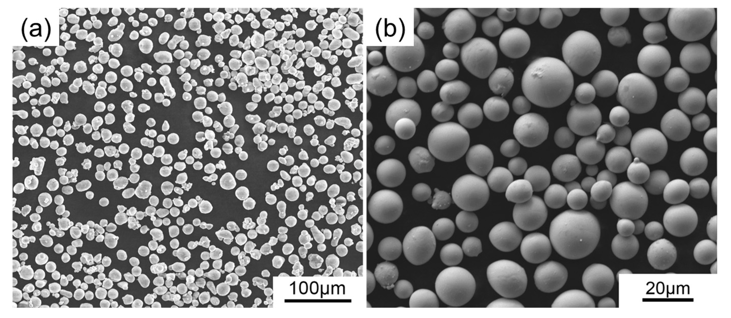
2.4. Microstructural Characterization and Property Evaluation

The microstructure of the Al-Ta ESM fabricated via HIP was characterized using HITACHI SU8500 scanning electron microscopy (SEM, Hitachi High-Tech, Tokyo, Japan) equipped with energy-dispersive X-ray spectroscopy (EDS).
The mechanical properties of the HIP-fabricated Al-Ta ESM were evaluated through quasi-static uniaxial compression testing at room temperature using a Instron 5569 universal testing machine (Instron corporation, Chicago, IL, USA). Cylindrical specimens with dimensions of φ4 × 8 mm3 were tested at a constant strain rate of 10−3 s−1.
The impact-induced reaction characteristics of the HIP-fabricated Al-Ta ESM were evaluated by ballistic gun testing. A cubic Al-Ta specimen (9 × 9 × 9.8 mm3) was launched at about 1000 m/s to penetrate a double-layered target consisting of a front steel target and a rear aluminum target with 200 mm inter-target spacing. The penetration process was comprehensively captured using high-speed photography.

3. Results and Discussion

3.1. Modified DPC Parameters of Al/Ta Mixed Powder

Figure 7 presents the original data and corresponding fitting curve for the modified DPC parameters of the Al-Ta mixed powder. The fitting procedure was performed based on the functional equations proposed by Zhou [14], utilizing the original data. In addition, the average deviations between the fitted results and the original data remained below 5%. For reference, the complete set of fitted functional equations is provided in the Supplementary Materials. In Figure 7, the parameters d and p b exhibit a clear dependence on relative density and temperature:
1. The strain hardening effect leads to an increase with rising relative density.
2. The thermal softening effect results in a decrease with increasing temperature.
In contrast, the variations of β and R with temperature are less pronounced. However, the following is observed:
1. β demonstrates a decreasing trend with higher relative density.
2. R shows an increasing trend with greater relative density.
Figure 7. Modified DPC parameters (original data and fitting curve) with different relative density of Al/Ta mixed powders at 300–750 K: (a) d ; (b) β ; (c) R ; (d) P b .
Metals 15 00615 g007

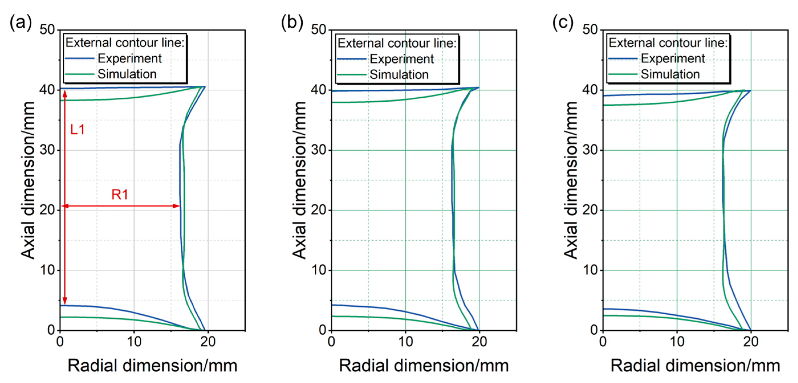
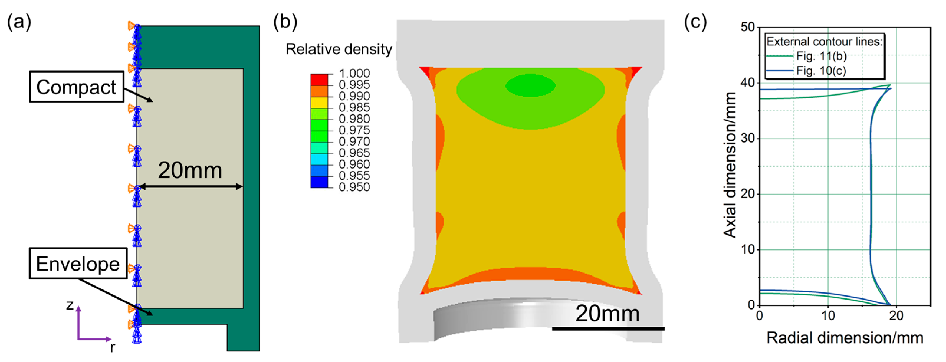
3.2. Verification of Modified DPC Parameters

Based on the modified DPC parameters, the average relative density distribution of the Al-Ta ESM fabricated via HIP was numerically simulated under varying temperature and pressure conditions, with a holding time of 2 h, as shown in Figure 8. Based on the results shown in Figure 8, the optimal HIP parameters (460 °C/140 MPa/2 h) for achieving an average relative density of 99% were selected for the sintering of the Al-Ta ESM. Furthermore, to prevent potential chemical reactions between Al and Ta during processing, which would damage the energy-release properties in application, two additional lower temperature HIP processes were employed: 400 °C/135 MPa/2 h and 340 °C/135 MPa/2 h.
Figure 9 shows a comparative analysis of the HIP simulation and experimental results. The sintered compacts were bisected along the central axis to obtain symmetrical cross-sections (Figure 9a–c). The external contour lines of the Al-Ta compacts were recorded based on high-resolution image recognition technology. Meanwhile, the external contour lines obtained by simulations (Figure 9d–f) were also recorded by exporting nodal coordinates. In addition, due to the bilateral symmetry exhibited by the sample cross-sections, only half of the external contour lines were analyzed when comparing the simulation and experimental results, as shown in Figure 10.
From Figure 10, the simulation results exhibit good agreement with the experimental data. To quantitatively evaluate the deviation between simulated and experimental results, two characteristic dimensions were compared: the axial dimension (L1) and the radial dimension (R1), as illustrated in Figure 10a. The comparative analysis of the obtained results is presented in Table 3. The deviations in characteristic dimensions are all within 5%, demonstrating that the modified DPC parameters of the Al/Ta mixed powders identified in this paper exhibit high accuracy.
However, it should be noticed that the simulation results show notable discrepancies with the experimental measurements in the external contour lines of both the top and bottom surfaces, specifically, as follows:
1. On the top surface, the simulation results display larger curvature than the experimental results.
2. On the bottom surface, the simulation results display smaller curvature than the experimental results.
These deviations may be due to the accumulation of solder at the top surface during vacuum sealing of the envelope. The accumulation of solder material at the top surface increases the effective thickness of the envelope, thereby constraining its deformation behavior. To verify this speculation, the geometric configuration of the HIP simulation model in Figure 4 was modified, as shown in Figure 11a. While maintaining all other conditions, the wall thickness of the upper envelope was increased from 3 mm to 8 mm. Under the HIP processing parameters of 460 °C/140 MPa/2 h, the simulation result is presented in Figure 11b. In Figure 11b, the external contour lines of the compact are exported and compared with the simulation result in Figure 10c. The comparative analysis is displayed in Figure 11c. The results indeed demonstrate that thickening the envelope directly induces a decrease in top-surface curvature and an increase in bottom-surface curvature.

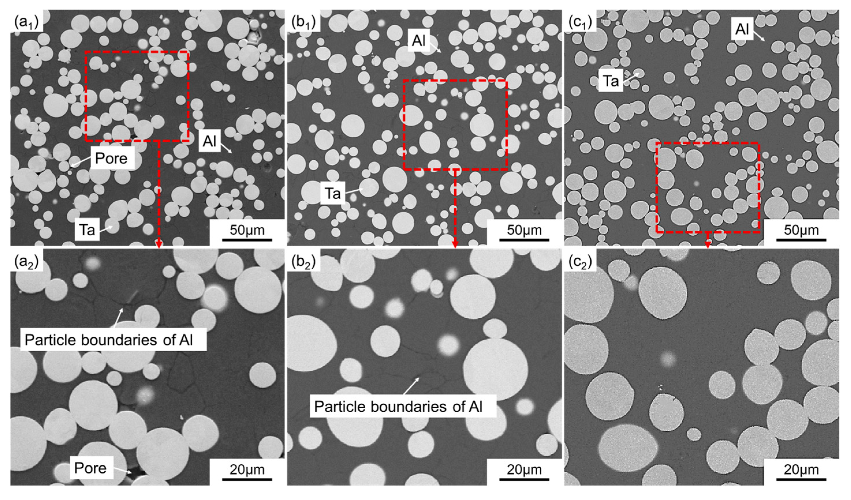
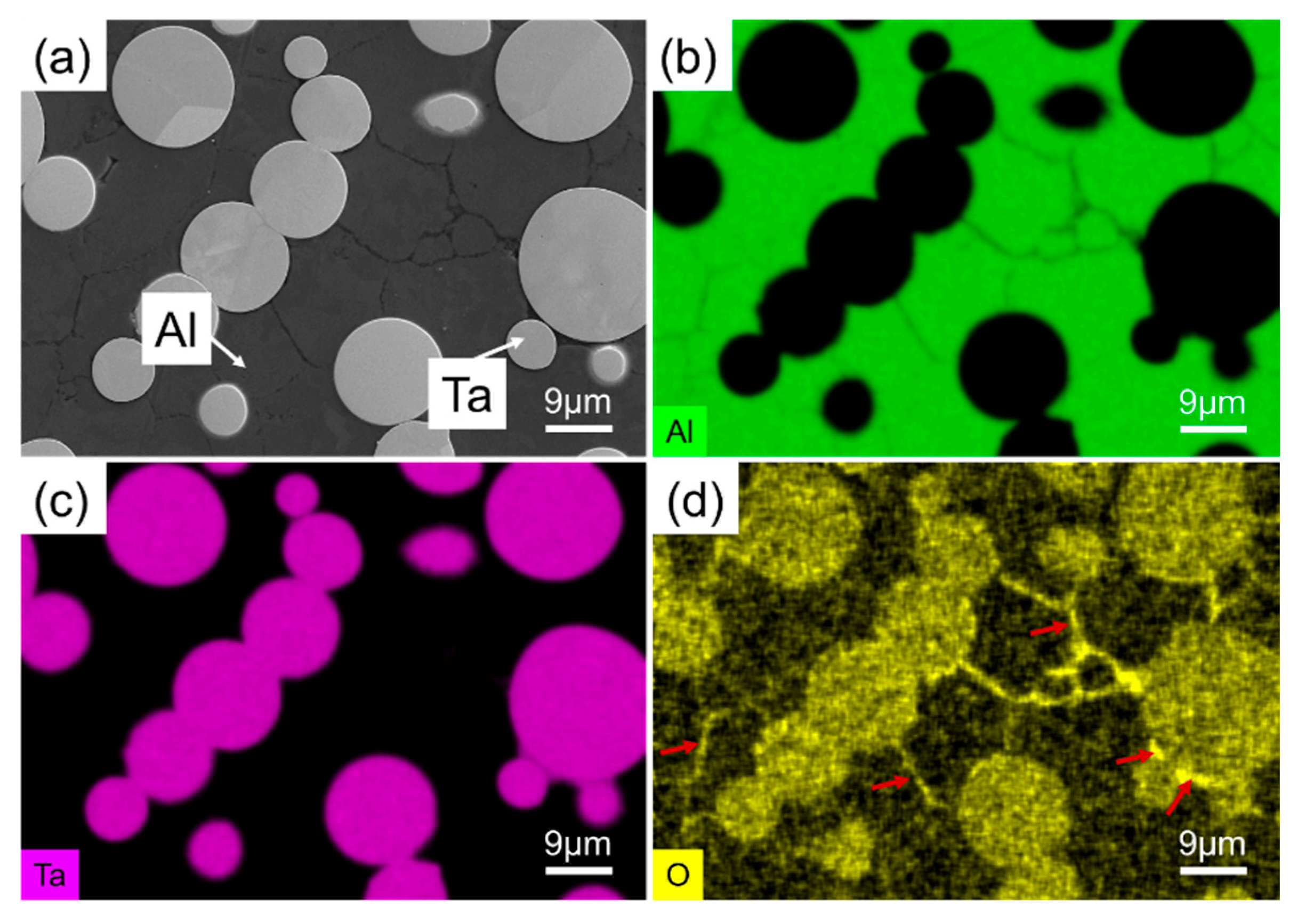
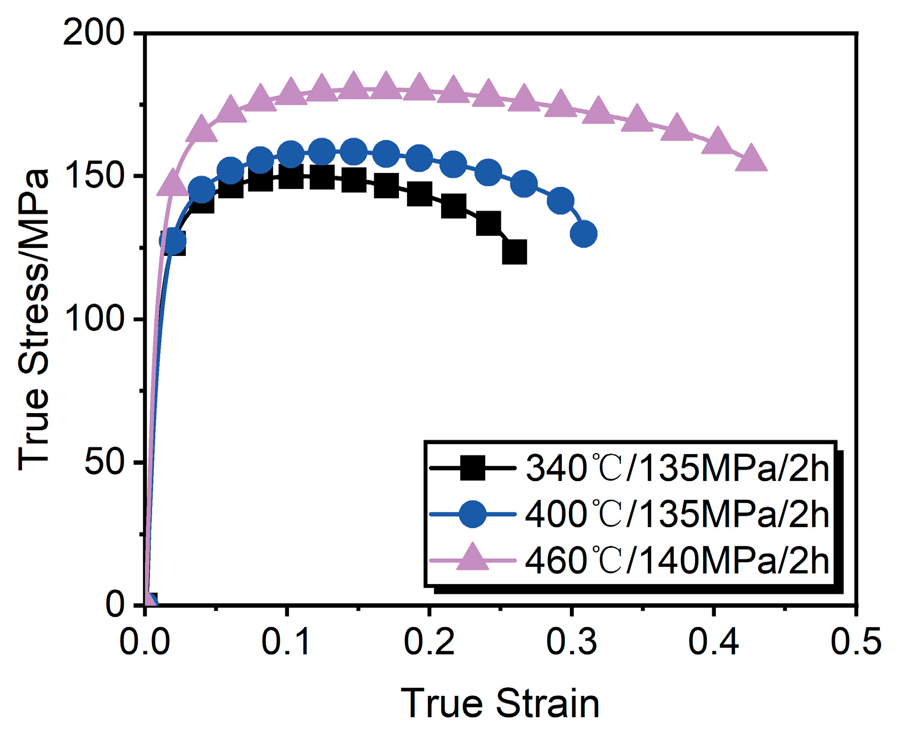
3.3. Microstructure and Mechanical Property Analysis

To determine whether chemical reactions occurred during the preparation of the Al-Ta ESM via HIP, the microstructures of samples (the sampling location was at the center of the cross-sectional view shown in Figure 9a–c) were analyzed by SEM, as illustrated in Figure 12. The microstructural analysis reveals distinct phase distribution without detectable AlxTay intermetallic formation. It confirms that no significant chemical reaction occurred between Al and Ta during HIP processing.
Microstructure analysis reveals a clear evolution in the densification behavior of the Al-Ta ESM under HIP. At the HIP temperature of 340 °C/135 MPa/2 h, the microstructure of Al-Ta exhibits significant porosity with distinct interparticle boundaries between Al, indicating incomplete consolidation of the Al-Ta ESM, as shown in Figure 12(a1,a2). With HIP at 400 °C/135 MPa/2 h, substantial pore elimination is achieved, though discernible Al boundaries persist, as shown in Figure 12(b1,b2). Optimal densification occurs at 460 °C/140 MPa/2 h, producing a fully dense microstructure with neither observable porosity nor residual Al particle boundaries, as shown in Figure 12(c1,c2).
Figure 13 presents the microstructure and corresponding elemental mapping (Al, Ta, and O) obtained by EDS for the Al-Ta ESM fabricated via HIP at 340 °C/135 MPa/2 h. The results reveal significant oxygen enrichment at both the interparticle boundaries between Al and the interfacial pores surrounding Ta particles, as indicated by the red arrows in Figure 13d. This oxygen accumulation likely originates from the native oxide layers present on the raw Al and Ta powder surfaces. According to previous research [38,39], these pre-existing oxide layers act as diffusion barriers that limit atomic interdiffusion across particle boundaries, critically impeding the densification behavior during HIP. This explains the observed poor interparticle bonding and residual porosity in the consolidated microstructure.
In addition, the poor interparticle bonding and residual porosity strongly deteriorate the mechanical properties. Figure 14 shows the true stress–strain relationships at a strain rate of 10−3 of the Al-Ta ESM fabricated by the three different HIP processes. The yield strength, compressive strength, and fracture strain (when the strength decreases to 90% of the compressive strength) were obtained from Figure 14, as shown in Table 4. It can be seen that the Al-Ta ESM fabricated by the HIP process at 460 °C/140 MPa/2 h has the best performance. This is because pores and poorly bonded interfaces between particles are prone to acting as nucleation sites for crack initiation during deformation. In addition, the subsequent damage propagation causes simultaneous deterioration in tensile strength and elongation [40,41,42]. In summary, the HIP process at 460 °C/140 MPa/2 h enables the fabrication of an Al-Ta ESM with a dense microstructure and excellent mechanical properties.

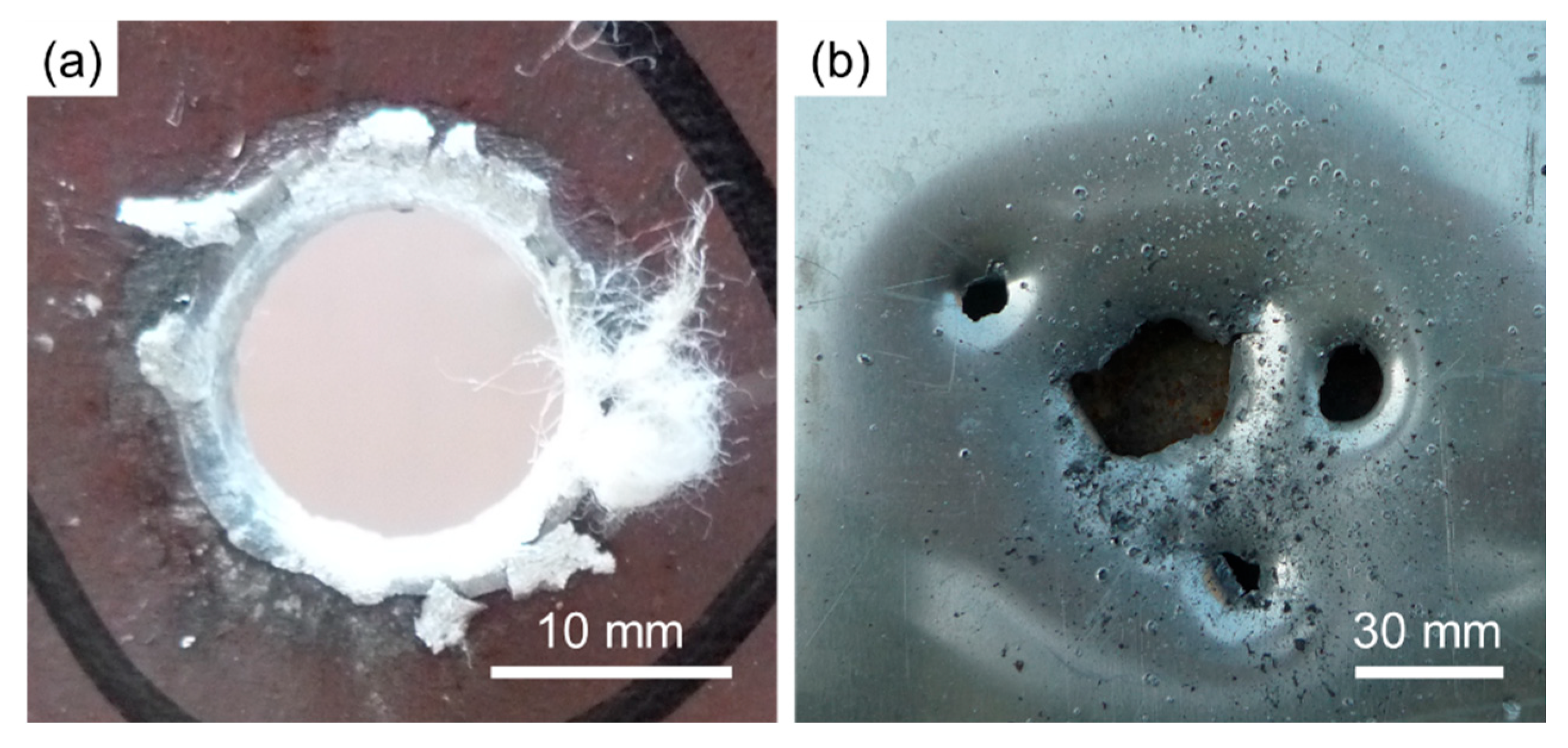
3.4. Impact-Induced Reaction Characteristics

This paper further evaluated the impact-induced reaction characteristics of the Al-Ta ESM fabricated through HIP (460 °C/140 MPa/2 h) using ballistic gun testing. The entire penetration process is shown in Figure 15. Figure 15a shows the Al-Ta specimen being launched from the ballistic gun. Subsequently, the specimen impacts the front steel target and triggers intense reactive behavior, producing a brilliant luminous flare, as shown in Figure 15b. The progression continues in Figure 15c, where the Al-Ta specimen penetrates through the front steel target and impacts the rear aluminum target in a characteristic fireball formation. Ultimately, the Al-Ta specimen perforates the rear aluminum target through the combined action of its residual kinetic energy and the chemical energy released by the reaction process, as shown in Figure 15d.
Figure 16 presents the macroscopic morphology of both the front steel target and the rear aluminum target following the ballistic gun testing of the Al-Ta specimen. The cross-sectional areas of perforation holes measured from these targets are tabulated in Table 5. It can be seen that the aluminum target hole area divided by the steel target hole area is 5.2 at the impact velocity of 1000 m/s. This value significantly exceeds the typical inert fragments (approximately 2 [43]) observed under comparable conditions. The above analysis demonstrates that the Al-Ta ESM fabricated via HIP at 460 °C/140 MPa/2 h in this paper can significantly enhance the damage effect on behind-target objects through combined kinetic penetration and chemical energy release, further confirming its excellent impact-induced reaction characteristics.

4. Conclusions

This paper achieved the simulation of HIP densification for an Al-Ta ESM and successfully synthesized the Al-Ta ESM via HIP, based on the modified DPC parameters of Al/Ta mixed powders identified by a multi-particle finite-element model. The microstructure, mechanical properties, and impact-induced reaction characteristics of the fabricated Al-Ta ESMs were systematically analyzed. The main findings are summarized as follows:
(1) The characteristic dimensions of Al-Ta compacts obtained from the HIP simulations and experiments showed excellent agreement. The minor discrepancies in external contour lines were primarily attributed to solder accumulation from the welding process at the envelope top surface. These results demonstrate that the developed multi-particle model and the identification of the modified DPC parameters exhibit high accuracy in predicting the densification behavior of Al/Ta mixed powder during HIP.
(2) The oxide layers on the powder surfaces significantly impeded the densification process of the Al-Ta ESM during HIP. This resulted in noticeable pores and distinct particle boundaries in the Al-Ta materials fabricated under HIP conditions of 340 °C/135 MPa/2 h and 400 °C/135 MPa/2 h. In contrast, the HIP process at 460 °C/140 MPa/2 h effectively overcame the hindering effect of oxide layers, producing a pore-free microstructure and eliminating particle boundaries. Furthermore, the Al-Ta ESM fabricated under 460 °C/140 MPa/2 h exhibited superior mechanical properties.
(3) The Al-Ta ESM fabricated via the optimized HIP process (460 °C/140 MPa/2 h) demonstrated excellent impact-induced reaction characteristics during penetration of double-layered targets. The combined effects of residual kinetic energy after perforating the steel target and subsequent energy release enabled effective penetration of the rear aluminum target. Compared to conventional inert fragments, this material exhibits significantly enhanced damage potential.

Supplementary Materials

The following supporting information can be downloaded at https://www.mdpi.com/article/10.3390/met15060615/s1: Table S1. Fitted functional equations for DPC Model in Figure 6 (ρ is the relative density).

Author Contributions

Conceptualization, Z.Y. and X.N.; methodology, Z.Y.; software, Z.Y.; validation, Z.Y., P.Z. and X.Y.; formal analysis, P.Z. and X.Y.; investigation, X.N.; resources, P.Z.; data curation, X.N.; writing—original draft preparation, Z.Y.; writing—review and editing, Z.Y., X.N. and C.T.; visualization, Z.Y.; supervision, X.Y.; project administration, X.Y. and C.T.; funding acquisition, C.T. All authors have read and agreed to the published version of the manuscript.

Funding

This research received no external funding.

Data Availability Statement

The original contributions presented in this study are included in the article/Supplementary Materials. Further inquiries can be directed to the corresponding author.

Acknowledgments

The authors would like to acknowledge the Central Iron & Steel Research Institute for its technical support in hot isostatic pressing.

Conflicts of Interest

Author Pengjie Zhang was employed by the company CISRI HIPEX Technology Co., Ltd. The remaining authors declare that the research was conducted in the absence of any commercial or financial relationships that could be construed as a potential conflict of interest.

References

  1. Fischer, S.; Grubelich, M. A Survey of Combustible Metals, Thermites, and Intermetallics for Pyrotechnic Applications, United States; Defense Technical Information Center: Fort Belvoir, VA, USA, 1996. [Google Scholar]
  2. Wei, C.T.; Vitali, E.; Jiang, F.; Du, S.W.; Benson, D.J.; Vecchio, K.S.; Thadhani, N.N.; Meyers, M.A. Quasi-static and dynamic response of explosively consolidated metal–aluminum powder mixtures. Acta Mater. 2012, 60, 1418–1432. [Google Scholar] [CrossRef]
  3. Aydelotte, B.B.; Thadhani, N.N. Mechanistic aspects of impact initiated reactions in explosively consolidated metal+ aluminum powder mixtures. Mater. Sci. Eng. A 2013, 570, 164–171. [Google Scholar] [CrossRef]
  4. Ni, R.; Zhang, P.; Che, L.; Lv, Z.; Chen, S.; Zhang, L.; Li, X. Effect of Powder Production Methods on Microstructure and Mechanical Properties of Hot Isostatically Pressed TA15 Alloy. J. Phys. Conf. Ser. 2025, 2956, 012035. [Google Scholar] [CrossRef]
  5. Shi, Y.; Wei, Q.; Xue, P.; Song, B. Integrated Hot Isostatic Pressing Technology for Complex Metal Parts; Huangzhong University of Science and Technology Press: Wuhan, China, 2018. [Google Scholar]
  6. Abdelhafeez, A.M.; Essa, K.E.A. Influences of powder compaction constitutive models on the finite element simulation of hot isostatic pressing. Procedia CIRP 2016, 55, 188–193. [Google Scholar] [CrossRef]
  7. Shima, S.; Oyane, M. Plasticity theory for porous metals. Int. J. Mech. Sci. 1976, 18, 285–291. [Google Scholar] [CrossRef]
  8. Resende, L.; Martin, J.B. Formulation of Drucker-Prager cap model. J. Eng. Mech. 1985, 111, 855–881. [Google Scholar] [CrossRef]
  9. Drucker, D.C.; Gibson, R.E.; Henkel, D.J. Soil mechanics and work-hardening theories of plasticity. Trans. Am. Soc. Civ. Eng. 1957, 122, 338–346. [Google Scholar] [CrossRef]
  10. Khoei, A.R.; Molaeinia, Z.; Keshavarz, S. Modeling of hot isostatic pressing of metal powder with temperature–dependent cap plasticity model. Int. J. Mater. Form. 2013, 6, 363–376. [Google Scholar] [CrossRef]
  11. Diarra, H.; Mazel, V.; Busignies, V.; Tchoreloff, P. Sensitivity of elastic parameters during the numerical simulation of pharmaceutical die compaction process with Drucker-Prager/Cap model. Powder Technol. 2018, 332, 150–157. [Google Scholar] [CrossRef]
  12. Park, H.; Kim, K.T. Consolidation behavior of SiC powder under cold compaction. Mater. Sci. Eng. A 2001, 299, 116–124. [Google Scholar] [CrossRef]
  13. Rottmann, G.; Coube, O.; Riedel, H. Comparison between triaxial results and model predictions with special consideration of the anisotropy. Proc. Eur. Congr. Powder Metall. 2001, 3, 29–37. [Google Scholar]
  14. Zhou, M.; Huang, S.; Hu, J.; Lei, Y.; Xiao, Y.; Li, B.; Yan, S.; Zou, F. A density-dependent modified Drucker-Prager Cap model for die compaction of Ag57. 6-Cu22. 4-Sn10-In10 mixed metal powders. Powder Technol. 2017, 305, 183–196. [Google Scholar] [CrossRef]
  15. Zhang, B.; Jain, M.; Zhao, C.; Bruhis, M.; Lawcock, R.; Ly, K. Experimental calibration of density-dependent modified Drucker-Prager/Cap model using an instrumented cubic die for powder compact. Powder Technol. 2010, 204, 27–41. [Google Scholar] [CrossRef]
  16. Ogawa, R.; Yoshimura, T.; Yagi, N.; Mizuta, K.; Taniguchi, Y. Estimation of Yield Surface on Iron Powder Compaction for Finite Element Analysis using Drucker-Prager Cap Model. Mater. Sci. Eng. Conf. Ser. 2019, 501, 012021. [Google Scholar] [CrossRef]
  17. Bai, W.; Liu, W.; Wang, W.; Peng, C.; Wang, A.; He, Q.; Liu, G.; Huang, S. Drucker-Prager-Cap modelling of boron carbide powder for coupled electrical-thermal-mechanical finite element simulation of spark plasma sintering. Ceram. Int. 2021, 47, 21536–21545. [Google Scholar] [CrossRef]
  18. Hibbitt, Karlsson and Sorensen, Inc. ABAQUS Version 6.14 Documentation; Dassault Systemes Simulia Corp: Johnston, RI, USA, 2018. [Google Scholar]
  19. Li, W.; Kou, H.; Zhang, X.; Ma, J.; Li, Y.; Geng, P.; Wu, X.; Chen, L.; Fang, D. Temperature-dependent elastic modulus model for metallic bulk materials. Mech. Mater. 2019, 139, 103194. [Google Scholar] [CrossRef]
  20. Davoudi, K. Temperature dependence of the yield strength of aluminum thin films: Multiscale modeling approach. Scr. Mater. 2017, 131, 63–66. [Google Scholar] [CrossRef]
  21. Peyre, P.; Braham, C. FEM calculation of residual stresses induced by laser shock processing in stainless steels. Model. Simul. Mater. Sci. Eng. 2007, 15, 205. [Google Scholar] [CrossRef]
  22. Huang, S.-L.; Zhou, Z. Experimental study on the mechanical behavior of material at mid-strain-rate. Build. Tech. Dev. 2005, 32, 2. [Google Scholar]
  23. Škoro, G.P.; Bennett, J.R.J.; Edgecock, T.R.; Gray, S.A.; McFarland, A.J.; Booth, C.N.; Rodgers, K.J.; Back, J.J. Dynamic Young’s moduli of tungsten and tantalum at high temperature and stress. J. Nucl. Mater. 2011, 409, 40–46. [Google Scholar] [CrossRef]
  24. Lee, B.-J.; Vecchio, K.S.; Ahzi, S.; Schoenfeld, S. Modeling the mechanical behavior of tantalum. Metall. Mater. Trans. A 1997, 28, 113–122. [Google Scholar] [CrossRef]
  25. Aydin, İ.; Briscoe, B.J.; Şanlitürk, K.Y. The internal form of compacted ceramic components: A comparison of a finite element modelling with experiment. Powder Technol. 1996, 89, 239–254. [Google Scholar] [CrossRef]
  26. Han, L.H.; Elliott, J.A.; Bentham, A.C.; Mills, A.; Amidon, G.E.; Hancock, B.C. A modified Drucker-Prager Cap model for die compaction simulation of pharmaceutical powders. Int. J. Solids Struct. 2008, 45, 3088–3106. [Google Scholar] [CrossRef]
  27. Hust, J.G.; Lankford, A.B. Thermal Conductivity of Aluminum, Copper, Iron, and Tungsten for Temperatures from 1 K to the Melting Point; National Bureau of Standards: Boulder, CO, USA, 1984. [Google Scholar]
  28. Tanda, G.; Misale, M. Measurement of total hemispherical emittance and specific heat of aluminum and Inconel 718 by a calorimetric technique. J. Heat Transf. 2005, 128, 302–306. [Google Scholar] [CrossRef]
  29. Liu, Z.; Wang, G.; Feng, Y.; Li, L. Study on constitutive parameters of 6061 aluminum alloy at high strain rate. Min. Metall. Eng. 2011, 31, 120–123. [Google Scholar]
  30. Savchenko, I.V.; Stankus, S.V. Thermal conductivity and thermal diffusivity of tantalum in the temperature range from 293 to 1800 K. Thermophys. Aeromech. 2008, 15, 679–682. [Google Scholar] [CrossRef]
  31. Arblaster, J.W. Thermodynamic Properties of Tantalum. J. Phase Equilibria Diffus. 2018, 39, 255–272. [Google Scholar] [CrossRef]
  32. Oladijo, P.; Awe, S.; Akinlabi, E.; Phiri, R.; Lebudi, C.; Phuti, R. High-Temperature Properties of Metal Matrix Composites. In Encyclopedia of Materials: Composites; Elsevier: Amsterdam, The Netherlands, 2021; pp. 360–374. [Google Scholar]
  33. Springer, G.; Tsai, S.W. Thermal Conductivities of Unidirectional Materials. J. Compos. Mater. 1967, 1, 166–173. [Google Scholar] [CrossRef]
  34. Hull, D.; Clyne, T.W. An Introduction to Composite Materials; Cambridge University Press: Cambridge, UK, 1996. [Google Scholar]
  35. Chen, Z.; Wang, X.; Giuliani, F.; Atkinson, A. Microstructural characteristics and elastic modulus of porous solids. Acta Mater. 2015, 89, 268–277. [Google Scholar] [CrossRef]
  36. Wolff, C.; Mercier, S.; Couque, H.; Molinari, A.; Bernard, F.; Naimi, F. Thermal-electrical-mechanical simulation of the nickel densification by Spark Plasma Sintering. Comparison with experiments. Mech. Mater. 2016, 100, 126–147. [Google Scholar] [CrossRef]
  37. Chernikova, E.S.; Raichenko, A.I.; Olevskii, E.A. An analysis of electric heating of a cemented carbide taking into consideration the temperature relationship of its characteristics. Sov. Powder Metall. Met. Ceram. 1992, 31, 936–940. [Google Scholar] [CrossRef]
  38. Mahmoud, M.M.; Link, G.; Thumm, M. The role of the native oxide shell on the microwave sintering of copper metal powder compacts. J. Alloys Compd. 2015, 627, 231–237. [Google Scholar] [CrossRef]
  39. Kim, Y.W.; Griffith, W.M.; Froes, F.H. Surface oxides in P/M aluminum alloys. JOM 1985, 37, 27–33. [Google Scholar] [CrossRef]
  40. Martin, J.W.; Doherty, R.D.; Cantor, B. Stability of Microstructure in Metallic Systems; Cambridge University Press: Cambridge, UK, 1997. [Google Scholar]
  41. Al-Maharma, A.Y.; Patil, S.P.; Markert, B. Effects of porosity on the mechanical properties of additively manufactured components: A critical review. Mater. Res. Express 2020, 7, 122001. [Google Scholar] [CrossRef]
  42. Chawla, N.; Shen, Y.-L. Mechanical behavior of particle reinforced metal matrix composites. Adv. Eng. Mater. 2001, 3, 357–370. [Google Scholar] [CrossRef]
  43. Peng, J.; Li, B.; Yuan, B.; Sun, X.; Yang, Q. Study on the behavioral characteristics of ladle covered active fragments penetrating double-layer aluminum targets. Chin. J. Explos. Propellants 2020, 43, 6. [Google Scholar]
Figure 1. Modified DPC model: yield surface (thick black line) and stress path (red line with arrow).
Metals 15 00615 g001
Figure 2. Real size of powders: (a) Al; (b) Ta. (c) Geometric distribution and mesh (green particles are Al and red particles are Ta). Size of generated particles: (d) Al; (e) Ta.
Metals 15 00615 g002
Figure 3. Schematic diagram of boundary conditions (green particles are Al and red particles are Ta).
Metals 15 00615 g003
Figure 4. Axisymmetric HIP model.
Metals 15 00615 g004
Figure 5. Powder morphology characterized by SEM: (a) spherical Al powder; (b) spherical Ta powder.
Metals 15 00615 g005
Figure 6. Schematic temperature and pressure routes of HIP.
Metals 15 00615 g006
Figure 8. Average relative density distribution of Al-Ta ESM obtained by HIP simulations.
Metals 15 00615 g008
Figure 9. HIP simulation and experimental results: (a) experimental results for 340 °C/135 MPa/2 h; (b) experimental results for 400 °C/135 MPa/2 h; (c) experimental results for 460 °C/140 MPa/2 h; (df): simulation results corresponding to conditions of (ac).
Metals 15 00615 g009
Figure 10. Comparative analysis of external contour profiles between experimental and simulated results under varying HIP process parameters: (a) 340 °C/135 MPa/2 h; (b) 400 °C/135 MPa/2 h; (c) 460 °C/140 MPa/2 h.
Metals 15 00615 g010
Figure 11. (a) Modified geometric configuration of HIP model; (b) simulation result of modified geometric configuration under 460 °C/140 MPa/2 h; (c) comparative analysis of Figure 10c and Figure 11b.
Metals 15 00615 g011
Figure 12. Microstructure of Al-Ta ESM fabricated by different HIP processes ((a2,b2,c2) are enlarged views of regions marked by red dashed lines in (a1,b1,c1)): (a1,a2) 340 °C/135 MPa/2 h; (b1,b2) 400 °C/135 MPa/2 h; (c1,c2) 460 °C/140 MPa/2 h.
Metals 15 00615 g012
Figure 13. (a) Microstructure of Al-Ta HIP processing at 340 °C/135 MPa/2 h. (bd) Corresponding element mapping in (a): (b) Al; (c) Ta; (d) O.
Metals 15 00615 g013
Figure 14. The true stress–strain relationships at a strain rate of 10−3 of Al-Ta ESMs fabricated by the three different HIP processes.
Metals 15 00615 g014
Figure 15. High-speed photography of the Al-Ta specimen penetrating the target (the red line represents the position of the steel target and the blue line represents the position of the aluminum target): (a) launched from the ballistic gun; (b) impacting the front steel target; (c) penetrating the front steel target; (d) penetrating the rear aluminum target.
Metals 15 00615 g015
Figure 16. Macroscopic morphology of target after ballistic gun test: (a) steel target; (b) aluminum target.
Metals 15 00615 g016
Table 1. Estimation of properties of Al-Ta ( φ is volume fraction, ω is mass fraction).
PropertiesMixing Law
Elastic modulus/GPa [32] E A l T a = E A l φ A l + E T a φ T a
Thermal conductivity/W·m−1·K−1 [33] λ A l T a = λ A l φ A l + λ T a φ T a
Specific heat/J·kg−1·K−1 [34] C p ( A l T a ) = C p A l ω A l + C p T a ω T a
Table 2. Porosity dependence of material parameters ( ρ is relative density).
PropertiesProperties as Density-Dependent
Elastic modulus/GPa [35] E ρ = ρ E ρ = 1.0
Thermal conductivity/W·m−1·K−1 [36] λ ρ = 2 ρ λ ρ = 1.0 3 ρ
Specific heat/J·kg−1·K−1 [37]
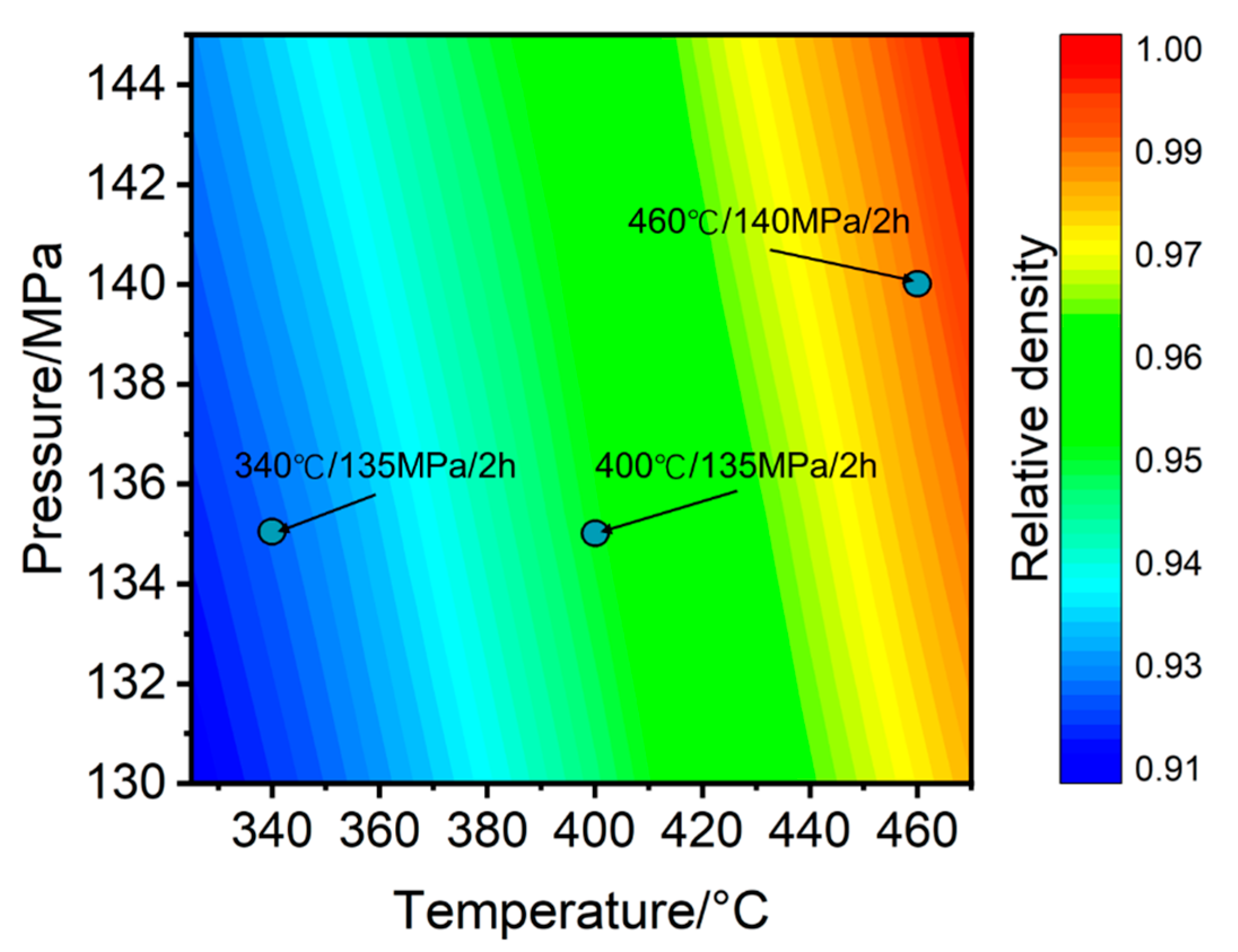
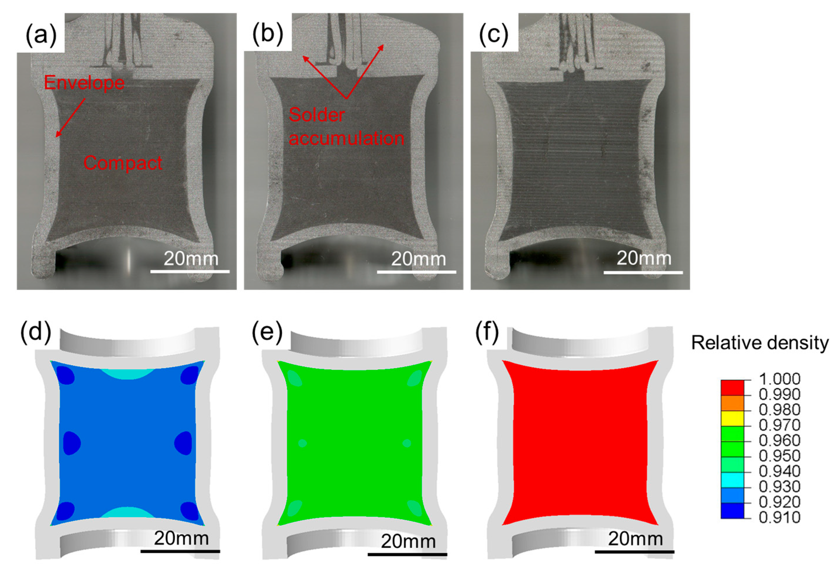
 C p ρ = C p ρ = 1.0
Table 3. Simulation and experimental results of characteristic dimensions L1 and R1.
HIP340 °C/135 MPa/2 h400 °C/135 MPa/2 h460 °C/140 MPa/2 h
L1/mmR1/mmL1/mmR1/mmL1/mmR1/mm
Experiment36.1416.1335.8316.1935.4716.13
Simulation35.6016.7835.5916.6635.1316.40
deviation/%1.54.00.72.90.91.7
Table 4. Mechanical properties of Al-Ta ESMs fabricated by different HIP processes.
HIPYield Strength/MPaCompressive Strength/MPaFracture Strain/%
340 °C/135 MPa/2 h96.7149.924.0
400 °C/135 MPa/2 h101.2158.628.8
460 °C/140 MPa/2 h115.2180.339.6
Table 5. Target hole area.
Steel TargetAluminum Target
Hole area/mm2184.17965.07
Disclaimer/Publisher’s Note: The statements, opinions and data contained in all publications are solely those of the individual author(s) and contributor(s) and not of MDPI and/or the editor(s). MDPI and/or the editor(s) disclaim responsibility for any injury to people or property resulting from any ideas, methods, instructions or products referred to in the content.

