


The Design and Microstructure Evolution Mechanism of New Cr1.3Ni2TiAl, CoCr1.5NiTi1.5Al0.2, and V0.3CoCr1.2NiTi1.1Al0.2 Eutectic High-Entropy Alloys

Abstract
1. Introduction
2. Materials and Methods
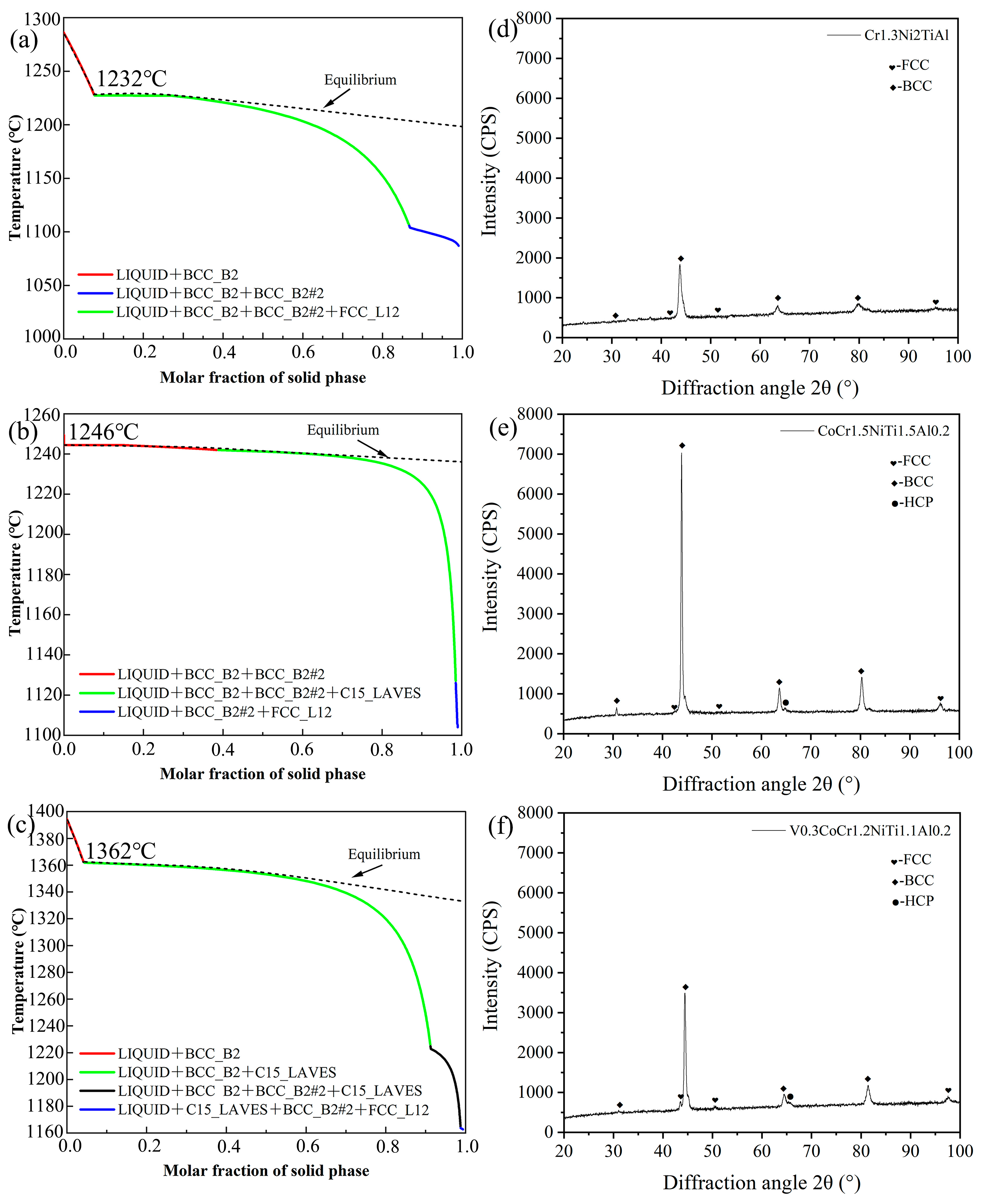
2.1. Theoretical Calculations and Phase Diagram Simulations
2.2. Raw Material Alloying Process
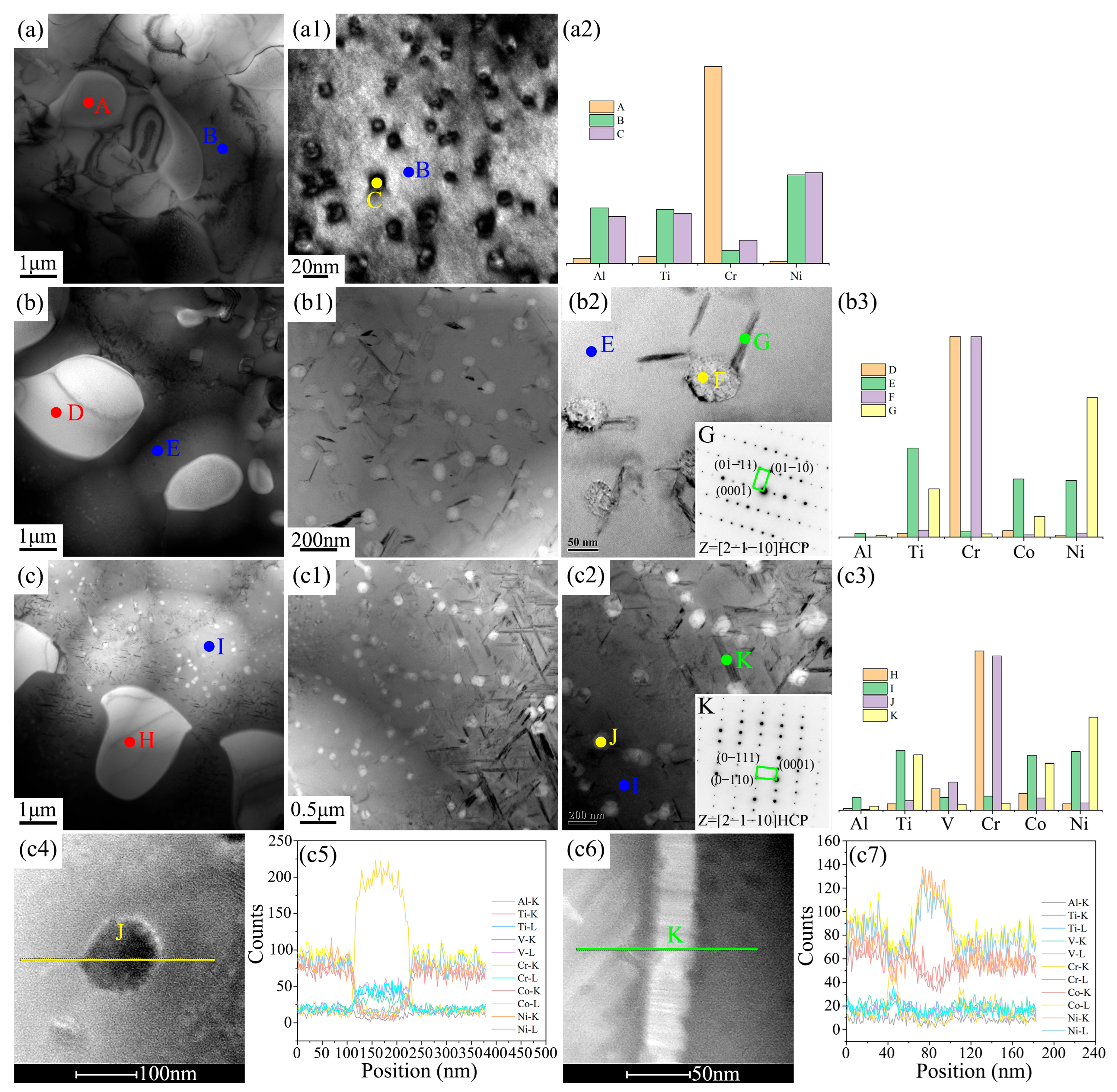
2.3. Microstructural Characterization
2.4. Mechanical Property Testing
3. Result and Discussion
4. Conclusions
Author Contributions
Funding
Data Availability Statement
Conflicts of Interest
References
- Lu, Y.P.; Dong, Y.; Guo, S.; Jiang, L.; Kang, H.J.; Wang, T.M.; Wen, B.; Wang, Z.J.; Jie, J.C.; Cao, Z.Q.; et al. A Promising New Class of High-temperature Alloys: Eutectic High-entropy Alloys. Sci. Rep. 2014, 4, 6200. [Google Scholar] [CrossRef] [PubMed]
- Miracle, D.B.; Senkov, O.N. A Critical Review of High Entropy Alloys and Related Concepts. Acta Mater. 2017, 122, 448–511. [Google Scholar] [CrossRef]
- Ye, Y.F.; Wang, Q.; Lu, J.; Liu, C.T.; Yang, Y. High-entropy Alloy: Challenges and Prospects. Mater. Today 2016, 19, 349–362. [Google Scholar] [CrossRef]
- Shi, P.; Ren, W.; Zheng, T.; Ren, Z.; Hou, X.; Peng, J.; Hu, P.; Gao, Y.; Zhong, Y.; Liaw, P.K. Enhanced Strength-ductility Synergy in Ultrafine-grained Eutectic High-entropy Alloys by Inheriting Microstructural Lamellae. Nat. Commun. 2019, 10, 489. [Google Scholar] [CrossRef]
- Liu, J.; Li, Z.; Lin, D.; Tang, Z.; Song, X.; He, P.; Zhang, S.; Bian, H.; Fu, W.; Song, Y. Eutectic High-entropy Alloys and Their Applications in Materials Processing Engineering: A Review. J. Mater. Sci. Technol. 2024, 189, 211–246. [Google Scholar] [CrossRef]
- Li, K.; Zhai, Y.; Lai, M.; Song, M.; Zou, S.; Huang, G.; Yaqoob, K.; Wang, Z.; Zhang, N. Corrosion of Eutectic High-entropy Alloys: A Review. Crystals 2023, 13, 1231. [Google Scholar] [CrossRef]
- Jia, Y.; Wang, Z.; Wu, Q.; Wei, Y.; Bai, X.; Liu, L.; Wang, J.; Liu, X.; Wang, L.; He, F.; et al. Boron Microalloying for High-temperature Eutectic High-entropy Alloys. Acta Mater. 2024, 262, 119427. [Google Scholar] [CrossRef]
- Ye, X.; Lei, H.; Liu, X.; Zhao, G.; Feng, J.; Chen, J.; Li, B.; Fang, D.; Gao, N. Design of Synergistic Alloying CoCrFeNi Eutectic High Entropy Alloy Based on Infinite Solid Solution. Mater. Lett. 2023, 343, 134395. [Google Scholar] [CrossRef]
- Chen, K.; Xiong, Z.; An, M.; Xu, Z.; Cheng, X. Large Strength and Decent Ductility at 600 °C Achieved in Bimodal Eutectic High-entropy Alloys. J. Mater. Res. Technol. 2023, 22, 3436–3441. [Google Scholar] [CrossRef]
- Yan, P.X.; Chang, J.; Wang, W.L.; Zhu, X.N.; Lin, M.J.; Wei, B. Eutectic Growth Kinetics and Microscopic Mechanical Properties of Rapidly Solidified CoCrFeNiMo0.8 High Entropy Alloy. Acta Mater. 2022, 237, 118149. [Google Scholar] [CrossRef]
- Jiao, W.; Jiang, H.; Qiao, D.; He, J.; Zhao, H.; Lu, Y.; Li, T. Effects of Mo on Microstructure and Mechanical Properties of Fe2Ni2CrMox Eutectic High Entropy Alloys. Mater. Chem. Phys. 2021, 260, 124175. [Google Scholar] [CrossRef]
- Zhang, L.; Lu, Y.; Amar, A.; Chen, X.; Ren, Z.; Wang, T.; Li, T. Eutectic High Entropy Alloys Containing B and Si with Excellent Mechanical Properties in Annealing. Mater. Sci. Eng. A 2022, 856, 143994. [Google Scholar] [CrossRef]
- Jiao, W.; Li, T.; Chang, X.; Lu, Y.; Yin, G.; Cao, Z.; Li, T. A Novel Co-free Al0.75CrFeNi Eutectic High Entropy Alloy with Superior Mechanical Properties. J. Alloys Compd. 2022, 902, 163814. [Google Scholar] [CrossRef]
- Zhang, W.; Ye, X.; Xu, D.; Liu, C.; Fang, D.; Li, B. Microstructures and Properties of CrxFeNi(3-x)Al High-entropy Alloys. Appl. Phys. A 2021, 128, 1. [Google Scholar] [CrossRef]
- Wu, M.; Wang, S.; Xiao, F.; Shen, G.; Tian, Y.; Yang, C.; Zhu, G.; Wang, D.; Shu, D.; Sun, B. Designing Lightweight Dual-phase Refractory VNbTiSi-based Eutectic High-entropy Alloys for Use at Elevated Temperatures. Mater. Sci. Eng. A 2022, 842, 143112. [Google Scholar] [CrossRef]
- Li, P.; Jia, Y.; Yi, J.; Ma, X.; Pu, J.; Wang, D. Composition Design, Microstructure and Mechanical Properties of Novel Multiphase Ti-Cu-Ni-Nb Complex Concentrated Alloys. J. Alloys Compd. 2020, 844, 156175. [Google Scholar] [CrossRef]
- Wu, Q.; He, F.; Li, J.; Kim, H.S.; Wang, Z.; Wang, J. Phase-Selective Recrystallization Makes Eutectic High-entropy Alloys Ultra-ductile. Nat. Commun. 2022, 13, 4697. [Google Scholar] [CrossRef]
- Jia, Y.; Wang, Z.; Wu, Q.; He, F.; Li, J.; Wang, J. Enhancing the Yield Strength of Ni-Co-Cr-Fe-Al as-Cast Hypoeutectic High-entropy Alloys by Introducing γ′ Precipitation. Mater. Sci. Eng. A 2022, 858, 144190. [Google Scholar] [CrossRef]
- Lee, C.F.; Shun, T.T. Effect of Fe Content on Microstructure and Mechanical Properties of Al0.5CoCrFexNiTi0.5 High-entropy Alloys. Mater. Charact. 2016, 114, 179–184. [Google Scholar] [CrossRef]
- Xiong, T.; Yang, W.; Zheng, S.; Liu, Z.; Lu, Y.; Zhang, R.; Zhou, Y.; Shao, X.; Zhang, B.; Wang, J.; et al. Faceted Kurdjumov-Sachs Interface-induced Slip Continuity in the Eutectic High-entropy Alloy, AlCoCrFeNi2.1. J. Mater. Sci. Technol. 2021, 65, 216–227. [Google Scholar] [CrossRef]
- Yin, X.; Dou, Y.K.; He, X.F.; Jin, K.; Wang, C.L.; Dong, Y.G.; Wang, C.Y.; Xue, Y.F.; Yang, W. Effects of Nb Addition on Charpy Impact Properties of TiVTa Refractory High-entropy Alloy. Acta Metall. Sin.-Engl. 2023, 36, 405–416. [Google Scholar] [CrossRef]
- Chen, X.; Xie, W.; Zhu, J.; Wang, Z.; Wang, Y.; Ma, Y.; Yang, M.; Jiang, W.; Yu, H.; Wu, Y.; et al. Influences of Ti Additions on the Microstructure and Tensile Properties of AlCoCrFeNi2.1 Eutectic High Entropy Alloy. Intermetallics 2021, 128, 107024. [Google Scholar] [CrossRef]
- Lu, J.; Wu, C.; Zeng, J.; Tu, H.; Wang, J.; Su, X. Phase Composition and Microhardness of the as-Cast and Long-time Annealed CoxNi2-xCrFeTi Multi-component Alloys. Mater. Res. Express 2019, 6, 056527. [Google Scholar] [CrossRef]
- Wang, J.; Zhang, M.; Wang, H.; Li, Z.; Cheng, X.; Zhang, B.; Li, J.; Ran, X. Mitigating Hot-cracking of Laser Melted CoCrFeNiMnTix High-entropy Alloys. Mater. Lett. 2022, 314, 131771. [Google Scholar] [CrossRef]
- Kim, J.; Na, Y.S.; Lim, K.R.; Chang, H.J. Effect of Trace Additions of Ti on the Microstructure of AlCoCrFeNi-based High Entropy Alloy. Sci. Adv. Mater. 2016, 8, 1984–1988. [Google Scholar] [CrossRef]
- Zhang, J.; Wang, M.; Wen, N.; Long, J.; Yan, D. Effect of Ti Addition on Microstructure Evolution and Mechanical Properties of Al18Co13Cr10Fe14Ni45 Eutectic High-entropy Alloys. Acta Metall. Sin.-Engl. 2023, 36, 1493–1501. [Google Scholar] [CrossRef]
- Li, S.; Chen, F.; Tang, X.; Ge, G.; Sun, Z.; Geng, Z.; Fan, M.; Huang, P. Effect of Ti on the Microstructure and Mechanical Properties of AlCrFeNiTix Eutectic High-entropy Alloys. J. Mater. Eng. Perform. 2022, 31, 8294–8303. [Google Scholar] [CrossRef]
- Gao, Y.; Han, J.; Ge, F.; Zhang, X.; Cai, Y.; Cui, Y. Design of Eutectic High-entropy Alloys in the Co-Cr-Ni-V-Ti-Al System Using Scheil Solidification Path Optimization. J. Alloys Compd. 2024, 1002, 175327. [Google Scholar] [CrossRef]
- Takeuchi, A.; Inoue, A. Classification of Bulk Metallic Glasses by Atomic Size Difference, Heat of Mixing and Period of Constituent Elements and Its Application to Characterization of the Main Alloying Element. Mater. Trans. 2005, 46, 2817–2829. [Google Scholar] [CrossRef]
- Chanda, B.; Jana, P.P.; Das, J. A Tool to Predict the Evolution of Phase and Young’s Modulus in High Entropy Alloys Using Artificial Neural Network. Comput. Mater. Sci. 2021, 197, 110619. [Google Scholar] [CrossRef]
- Zhang, Y.; Zhou, Y.J.; Lin, J.P.; Chen, G.L.; Liaw, P.K. Solid-solution Phase Formation Rules for Multi-component Alloys. Adv. Eng. Mater. 2008, 10, 534–538. [Google Scholar] [CrossRef]
- Yang, X.; Zhang, Y. Prediction of High-Entropy Stabilized Solid-solution in Multi-component Alloys. Mater. Chem. Phys. 2012, 132, 233–238. [Google Scholar] [CrossRef]
- Zhang, Y.; Lu, Z.; Ma, S.; Liaw, P.K.; Tang, Z.; Cheng, Y.; Gao, M. Guidelines in Predicting Phase Formation of High-entropy Alloys. MRS Commun. 2014, 4, 57–62. [Google Scholar] [CrossRef]
- Fang, S.; Xiao, X.; Xia, L.; Li, W.; Dong, Y. Relationship between the Widths of Supercooled Liquid Regions and Bond Parameters of Mg-based Bulk Metallic Glasses. J. Non-Cryst. Solids. 2003, 321, 120–125. [Google Scholar] [CrossRef]
- Allred, A.L. Electronegativity Values from Thermochemical Data. J. Inorg. Nucl. Chem. 1961, 17, 215–221. [Google Scholar] [CrossRef]
- Fang, S.S.; Zhou, Z.Q.; Zhang, J.L.; Yao, M.Y.; Feng, F.; Northwood, D.D. Two Mathematical Models for the Hydrogen Storage Properties of AB2 Type Alloys. J. Alloys Compd. 1999, 293–295, 10–13. [Google Scholar] [CrossRef]
- Yang, X.; Chen, S.; Cotton, J.D.; Zhang, Y. Phase Stability of Low-density, Multiprincipal Component Alloys Containing Aluminum, Magnesium, and Lithium. JOM 2014, 66, 2009–2020. [Google Scholar] [CrossRef]
- Tsai, M.; Tsai, K.; Tsai, C.; Lee, C.; Juan, C.; Yeh, J. Criterion for Sigma Phase Formation in Cr- and V-containing High-entropy Alloys. Mater. Res. Lett. 2013, 1, 207–212. [Google Scholar] [CrossRef]
- Guo, S.; Liu, C.T. Phase stability in high entropy alloys: Formation of Solid-solution Phase or Amorphous Phase. Prog. Nat. Sci. Mater. Int. 2011, 21, 433–446. [Google Scholar] [CrossRef]
- Huo, W.; Zhou, H.; Fang, F.; Xie, Z.; Jiang, J. Microstructure and Mechanical Properties of CoCrFeNiZrx Eutectic High-entropy Alloys. Mater. Des. 2017, 134, 226–233. [Google Scholar] [CrossRef]
- Kaufman, L. CALPHAD: Computer Coupling of Phase Diagrams and Thermochemistry—Foreword. Calphad 2002, 26, 141. [Google Scholar] [CrossRef]
- Gao, Y.; Cai, Y.; Cui, Y.; Yan, Y.; Wang, K. Design of Novel Structural Eutectic High Entropy Alloys (EHEAs) Containing High-temperature Resistant Alloying Elements. Intermetallics 2024, 175, 108535. [Google Scholar] [CrossRef]
- Easton, M.; StJohn, D. Grain Refinement of Aluminum Alloys: Part I. the Nucleant and Solute Paradigms. Metall. Mater. Trans. A 2001, 32, 1915–1925. [Google Scholar] [CrossRef]
- Thijs, L.; Kempen, K.; Kruth, J.-P.; Van Humbeeck, J. Fine-structured Aluminium Products with Controllable Texture by Selective Laser Melting of Pre-alloyed AlSi10Mg Powder. Acta Mater. 2013, 61, 1809–1819. [Google Scholar] [CrossRef]


| ΔHmix (kJ·mol−1) | V | Co | Cr | Ni | Ti | Al |
|---|---|---|---|---|---|---|
| - | −14 | −2 | −18 | −2 | −16 | |
| - | −4 | 0 | −28 | −19 | ||
| - | −7 | −2 | −10 | |||
| - | −35 | −22 | ||||
| - | −30 | |||||
| - | ||||||
| r (Å) | 1.35 | 1.25 | 1.29 | 1.25 | 1.47 | 1.43 |
| T (K) | 2163 | 1768 | 2130 | 1728 | 1941 | 933 |
| χ | 1.63 | 1.88 | 1.66 | 1.91 | 1.54 | 1.61 |
| VEC | 5 | 9 | 6 | 10 | 4 | 3 |
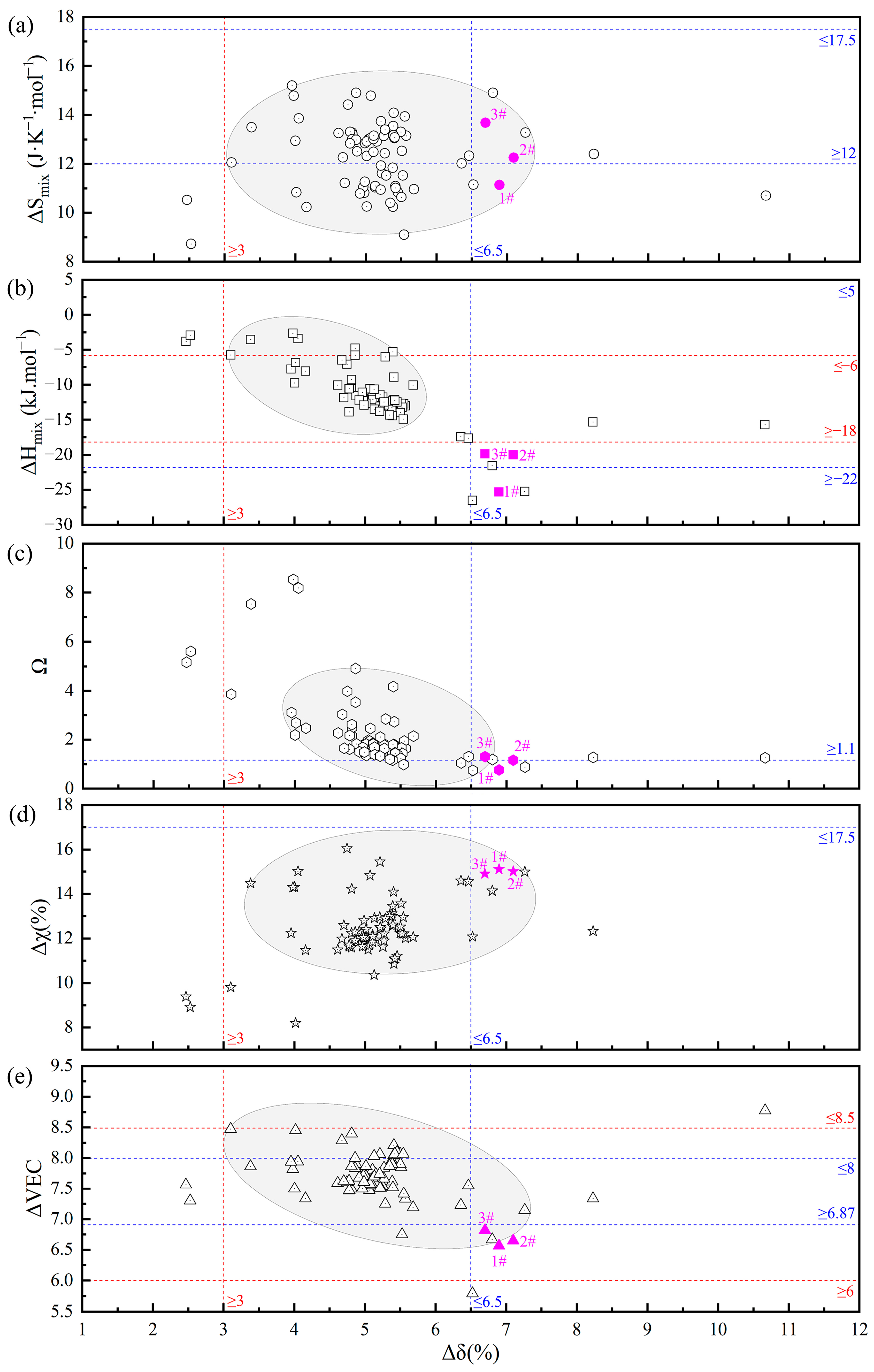
| Physical Parameters | Range | Structure |
|---|---|---|
| ∆Smix (J·K−1·mol−1) | 12 ≤ ∆Smix ≤ 17.5 | Solid solution |
| ∆δ (%) [31,32] | <6.5 | Solid solution |
| ∆Hmix (kJ·mol−1) [31,33] | −22 ≤ ∆Hmix ≤ 5 | Solid solution |
| Ω [33] | ≥1.1 | Solid solution |
| Δχ (%) [34,35,36] | ≤17.5 | Solid solution |
| VEC [37,38] | VEC < 6.87 | BCC Solid solution |
| 6.87 ≤ VEC < 8.0 | FCC+BCC Solid solution | |
| VEC ≥ 8.0 | FCC Solid solution |
| Co | Cr | Ni | Ti | V | Al | ||
|---|---|---|---|---|---|---|---|
| Cr1.3Ni2TiAl | Theoretical value | - | 24.5 | 37.7 | 18.9 | - | 18.9 |
| Actual value | - | 26.1 | 38.7 | 16.8 | - | 18.4 | |
| CoCr1.5NiTi1.5Al0.2 | Theoretical value | 19.2 | 28.8 | 19.2 | 28.8 | - | 3.8 |
| Actual value | 20.7 | 29.2 | 20.3 | 26.1 | - | 3.7 | |
| V0.3CoCr1.2NiTi1.1Al0.2 | Theoretical value | 20.8 | 25.0 | 20.8 | 22.9 | 6.3 | 4.2 |
| Actual value | 21.9 | 26.1 | 21.3 | 20.3 | 6.6 | 3.8 |
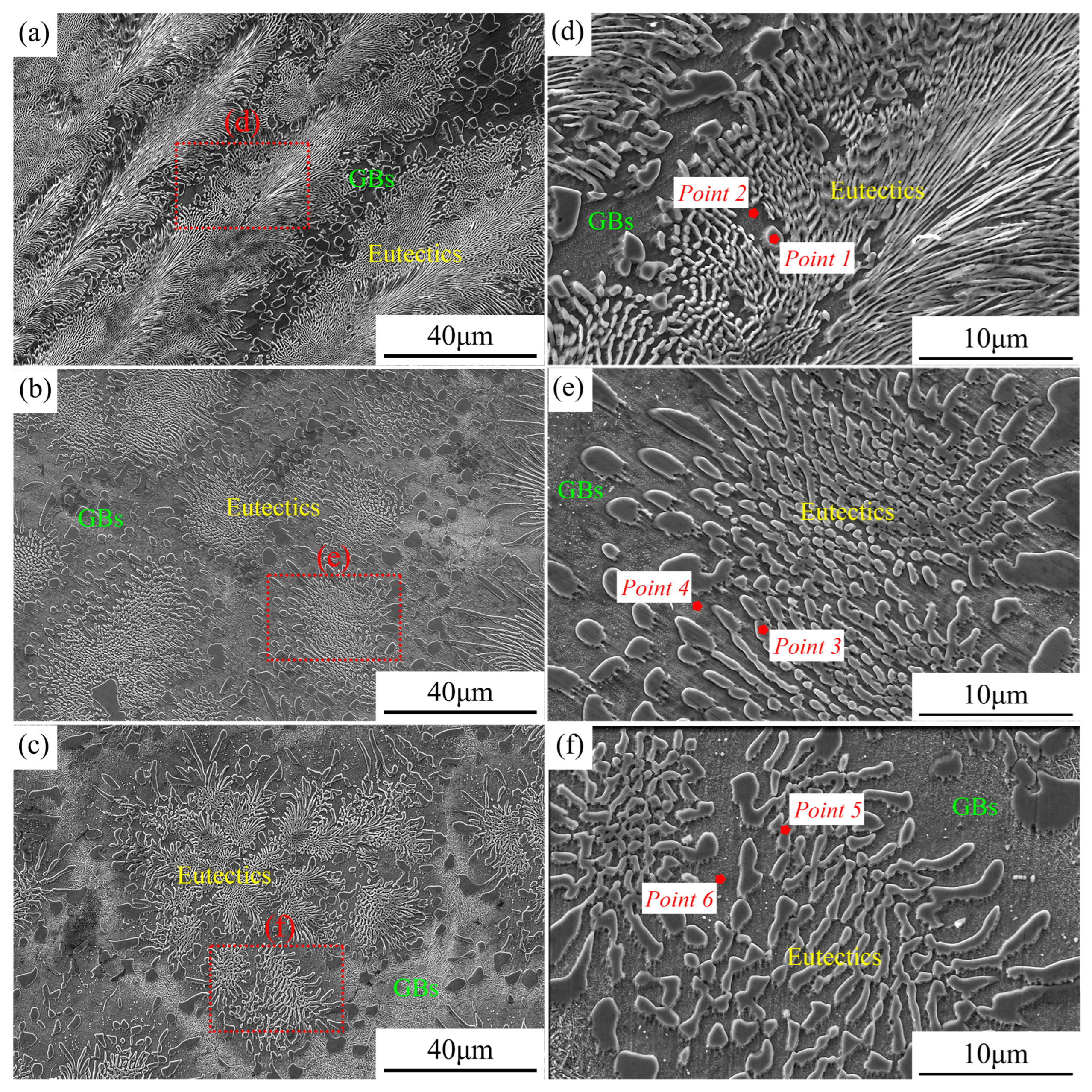
| Co | Cr | Ni | Ti | V | Al | |
|---|---|---|---|---|---|---|
| Point 1 | - | 94.04 | 2.24 | 2.56 | - | 1.14 |
| Point 2 | - | 4.42 | 62.21 | 21.08 | - | 12.27 |
| Point 3 | 3.81 | 91.80 | 1.13 | 3.21 | - | 0.02 |
| Point 4 | 27.69 | 7.12 | 31.03 | 31.80 | - | 2.34 |
| Point 5 | 9.78 | 72.79 | 3.05 | 2.61 | 11.48 | 0.28 |
| Point 6 | 30.44 | 6.87 | 28.98 | 25.16 | 5.36 | 3.15 |
Disclaimer/Publisher’s Note: The statements, opinions and data contained in all publications are solely those of the individual author(s) and contributor(s) and not of MDPI and/or the editor(s). MDPI and/or the editor(s) disclaim responsibility for any injury to people or property resulting from any ideas, methods, instructions or products referred to in the content. |
© 2025 by the authors. Licensee MDPI, Basel, Switzerland. This article is an open access article distributed under the terms and conditions of the Creative Commons Attribution (CC BY) license (https://creativecommons.org/licenses/by/4.0/).
Share and Cite
Zhang, X.; Yan, H.; Xiao, Y.; Feng, W.; Cai, Y. The Design and Microstructure Evolution Mechanism of New Cr1.3Ni2TiAl, CoCr1.5NiTi1.5Al0.2, and V0.3CoCr1.2NiTi1.1Al0.2 Eutectic High-Entropy Alloys. Metals 2025, 15, 613. https://doi.org/10.3390/met15060613
Zhang X, Yan H, Xiao Y, Feng W, Cai Y. The Design and Microstructure Evolution Mechanism of New Cr1.3Ni2TiAl, CoCr1.5NiTi1.5Al0.2, and V0.3CoCr1.2NiTi1.1Al0.2 Eutectic High-Entropy Alloys. Metals. 2025; 15(6):613. https://doi.org/10.3390/met15060613
Chicago/Turabian StyleZhang, Xin, Haitao Yan, Yao Xiao, Wenxin Feng, and Yangchuan Cai. 2025. "The Design and Microstructure Evolution Mechanism of New Cr1.3Ni2TiAl, CoCr1.5NiTi1.5Al0.2, and V0.3CoCr1.2NiTi1.1Al0.2 Eutectic High-Entropy Alloys" Metals 15, no. 6: 613. https://doi.org/10.3390/met15060613
APA StyleZhang, X., Yan, H., Xiao, Y., Feng, W., & Cai, Y. (2025). The Design and Microstructure Evolution Mechanism of New Cr1.3Ni2TiAl, CoCr1.5NiTi1.5Al0.2, and V0.3CoCr1.2NiTi1.1Al0.2 Eutectic High-Entropy Alloys. Metals, 15(6), 613. https://doi.org/10.3390/met15060613