Article

Effects of TiC Addition on Mechanical Behavior and Cutting Performance of Powder Extrusion Printed Cemented Carbides

1
Guangdong Engineering Technology Research Center of Ocean Equipment and Manufacturing, School of Mechanical Engineering, Guangdong Ocean University, Zhanjiang 524088, China
2
School of Electromechanical Engineering, Guangdong University of Technology, Guangzhou 510006, China
*
Author to whom correspondence should be addressed.
These authors contributed equally to this work.
Metals 2025, 15(5), 561; https://doi.org/10.3390/met15050561
Submission received: 22 April 2025 / Revised: 11 May 2025 / Accepted: 15 May 2025 / Published: 19 May 2025

Abstract

:
This study addresses the limited research on the mechanical behavior and cutting performance of additive manufactured cemented carbides with high TiC content, which has impeded the rapid development of additive manufacturing in carbide cutting tools. Using powder extrusion printing (PEP) additive manufacturing technology, we successfully fabricated WC-10TiC-12Co and WC-20TiC-12Co carbides with a relative density exceeding 97%. We investigated the effects of TiC content on the mechanical properties and cutting performance of WC-12Co carbide tools. The results show that TiC addition significantly affects the mechanical properties and cutting performance of PEP-processed carbides. Adding 10 wt.% and 20 wt.% TiC increases the Vickers hardness to 1403 HV30 and 1496 HV30, respectively, compared to 1317 HV30 for WC-12Co without TiC. However, TiC addition reduces the flexural strength from 2025 MPa for WC-12Co to 1434 MPa with 10 wt.% TiC and further to 915 MPa with 20 wt.% TiC. Tribological testing indicates that TiC addition reduces the friction coefficient and enhances wear resistance. HT250 cutting tests reveal that TiC addition significantly improves wear resistance and reduces workpiece surface roughness, particularly during longer cutting durations. This study broadens the scope of carbide materials suitable for PEP additive manufacturing.

1. Introduction

Cemented carbide, as a metal-ceramic composite tooling material, offers superior properties compared to other tooling materials. It exhibits high compressive strength, excellent wear resistance, exceptional hardness, a high elastic modulus, strong impact resistance, good vibration damping performance, corrosion resistance, and dimensional stability [1]. These outstanding mechanical properties have led to its widespread use in cutting tool manufacturing [2]. Extensive research has been conducted on traditional WC-Co cemented carbides, showing that adjusting the Co content in WC-Co alloys can precisely manipulate microstructure and therefore the mechanical properties [3,4]. Additionally, incorporating Ti(C,N) additives or modifying the Ti content in WC-Ti-Co systems improves mechanical performance by promoting grain refinement and suppressing abnormal grain growth, ultimately enhancing tool wear resistance [5,6,7,8,9]. However, as technological demands advance, traditional powder metallurgy faces increasing challenges in forming complex parts and structures, limiting the further development and application of cemented carbide tools.
Additive manufacturing (AM) enables the production of complex structural components, offering a viable solution to the limitations of traditional powder metallurgy in creating intricate geometries. For WC-Co cemented carbides, two main AM process routes exist: thermal-based powder bed fusion (PBF) and cold-forming-based forming-debinding-sintering (FDS) [10,11]. PBF technologies, such as selective laser melting (SLM) and selective electron beam melting (SEBM), often encounter challenges related to heterogeneous WC grain growth and low relative density in cemented carbide samples [12,13,14,15]. In WC-Co cemented carbides with cobalt content between 9–25 wt.%, the combination of a steep thermal gradient, rapid cooling, and a high liquid-phase proportion significantly constrains dimensional contraction during sintering. This leads to low relative density, increased porosity, and heterogeneous WC grain growth. In contrast, FDS, which includes debinding and sintering as post-processing steps, operates at a stable forming temperature, with prolonged sintering durations and complete material melting. These attributes enhance densification and eliminate internal porosity, resulting in cemented carbides with high relative density [16,17,18,19].
Among cold-forming technologies, two widely used methods are binder jetting (BJ or 3DP) and powder extrusion printing (PEP). The BJ process typically utilizes granulated powders, which can introduce significant interparticle porosity during powder spreading. This porosity may cause WC abnormal grain growth and inhomogeneous microstructure during sintering [20,21,22]. In contrast, PEP employs micron-, submicron-, or even nano-sized WC and Co powders, significantly improving the sintering activity, densification efficacy, and microstructural homogeneity. In recent years, extrusion-based additive manufacturing has made significant progress in a growing range of materials, including ceramic and metal powders, demonstrating significant application potentials in aerospace, mechanical processing, and cutting tool industries [23,24,25,26,27,28]. Chen et al. systematically investigated PEP fabrication of WC-9 wt.%Co cemented carbides through optimized feedstock powder design and printing parameters [29]. Their methodology achieved near-full density with homogeneous microstructural characteristics, yielding mechanical properties comparable to conventional powder metallurgy counterparts. Zhao et al. developed a paraffin/polymer binder system for WC-8 wt.%Co systems, revealing critical atmosphere-dependent sintering mechanisms [30]. Subsequent work advanced this through an optimization of the organic binder system, demonstrating that polyvinyl butyral (PVB) content governs green part strength [31].
While PEP processing has emerged as an important additive manufacturing (AM) technique for cemented carbides, current research remains predominantly confined to the WC-Co system. This persistent focus on such limited compositions substantially limits both the expansion of processable carbide systems and the broader technological implementation of PEP-based AM. Crucially, little systematic studies have been reported yet regarding PEP fabrication of TiC-modified WC-Co carbides—a critical research gap given TiC’s established role in enhancing high-temperature performance and wear resistance. To address this technological bottleneck, we present the comprehensive investigation of WC-xTiC-12Co composites fabricated through PEP, systematically varying TiC content from 0 to 20 wt.% while maintaining a constant 12 wt.% Co binder phase. The carbides underwent a two-step debinding process followed by sinter-hip to produce the final cemented carbide components. The study systematically examined the effect of TiC content on the microstructure and key mechanical properties of PEP-fabricated cemented carbides. Additionally, the cutting performance of the PEP processed cemented carbide tools was evaluated.

2. Materials and Methods

2.1. Materials

The WC and Co powders used in this study, with similar average particle sizes of 1 μm, were supplied by Xiamen Golden Egret Special Alloy Co., Ltd. (Xiamen, China) (Figure 1a,b). The TiC powder, with an average particle size of 1 μm, was supplied by Shanghai Shuitian Materials Technology Co., Ltd. (Shanghai, China) (Figure 1c).

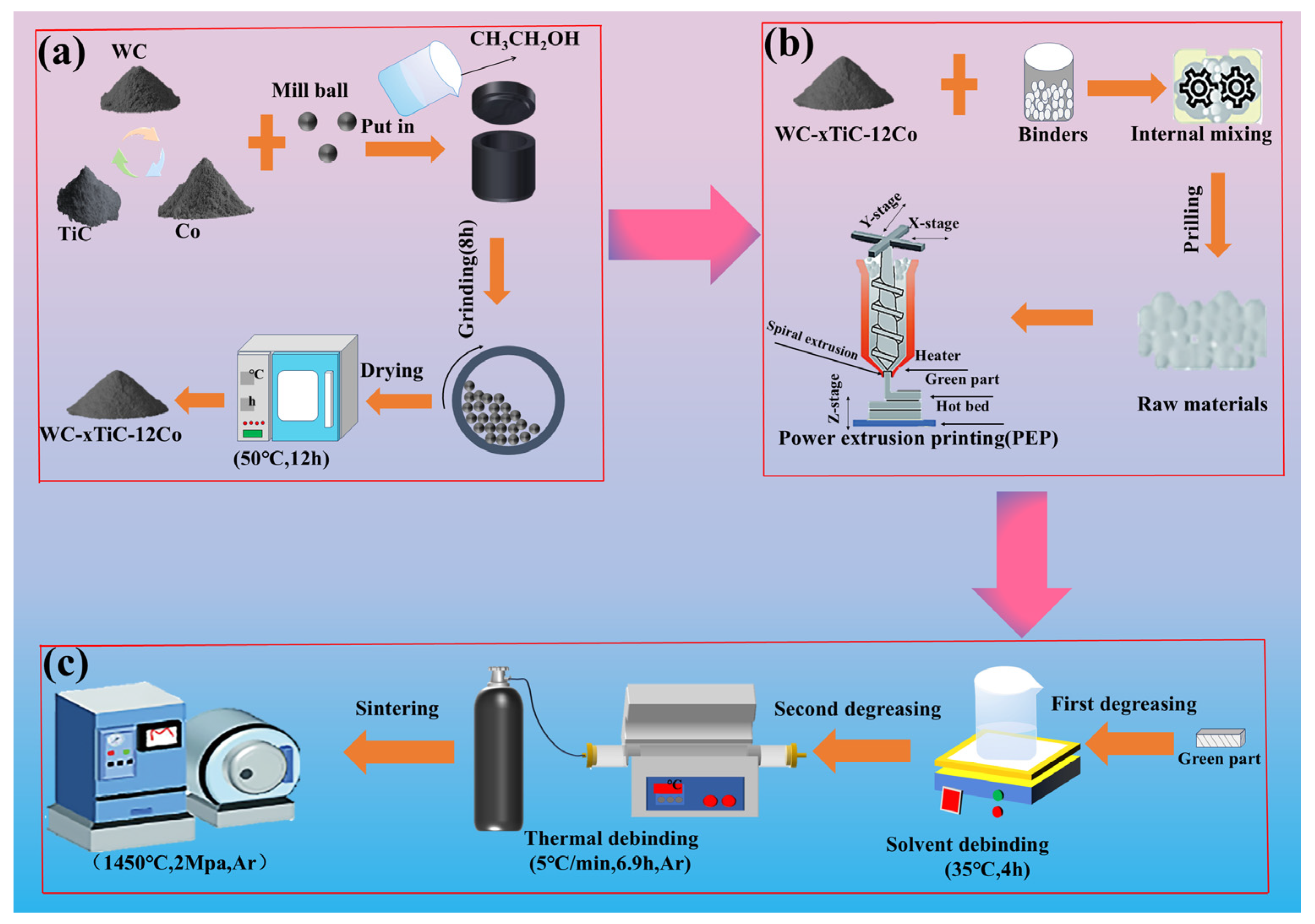
2.2. PEP and Post-Processes

Figure 2 schematically demonstrates the whole PEP processing, including feedstock powder mixing (Figure 2a), kneading and printing (Figure 2b), and debinding and sintering (Figure 2c). The WC, TiC, and Co powders were mixed via ball milling according to the compositions listed in Table 1. The ball milling was processed in a horizontal ball mill for 8 h with anhydrous ethanol as the milling medium. Carbide milling balls with 8 mm diameter were employed to improve the milling efficiency. The powder-ball weight ratio was set at 1:1. Upon ball milling, the carbide slurries were then thoroughly dried to obtain the cemented carbide powder mixtures (Figure 2a). Then the dried carbide powder mixtures were kneaded into carbide pellets with 2 mm diameter and 3 mm length before PEP processing was performed.
The kneading process was conducted by adding a thermoplastic binder to the dried carbide mixtures using an Open-Close Type Internal Mixer (UP-M0300 experimental mixer, Shenzhen Shenghua 3D Technology Co., Ltd., Shenzhen, China) at 165 °C and 30 r/min for 2 h. A volume fraction of 51% was set for the carbide phase. A paraffin-based thermoplastic organic binder synthesized in-house was employed. The carbide pellets were fed to a PEP equipment (Shenzhen Shenghua 3D Technology Co., Ltd.) for printing process. The precision limitations of the PEP equipment may somewhat affect the dimensional accuracy of the printed carbide parts but do not significantly impact the research outcomes. Cemented carbide tools and test specimens were designed in 3D modeling software (UG, 10.0, Siemens PLM Software, Plano, TX, USA), exported as STL files, and imported into the printer software. The key PEP processing parameters, including layer thickness, printing speed, and nozzle temperature are listed in Table 2. After printing, the base plate of the printer was cooled to room temperature before the green parts were detached for further debinding and sintering (Figure 2b).
A two-step debinding process was applied to the printed green bodies [32]. First, the green bodies were immersed in n-heptane for solvent debinding (35 °C, 4 h). After drying, they underwent secondary debinding in a tubular furnace under a combined argon and vacuum atmosphere. The temperature was raised from room temperature to 200 °C at 5 °C/min, held for 1 h, then increased to 450 °C at the same rate for another 1 h, and finally heated to 600 °C and held for 1 h. As the binder decomposed, eliminating the bonding bridges between powder particles, the debond parts exhibited low strength and became prone to structural damage during handling. To address this issue, the samples were presintered by heating from 600 °C to 1000 °C under vacuum (0.1 Pa) at 5 °C/min for 1 h. This induced partial solid-state sintering, enhancing the strength of the debond parts. The temperature curve for the thermal debinding and presintering processes is shown in Figure 3a. Finally, the debond bodies were sintered in a pressure sintering furnace under an argon atmosphere at 1450 °C and 2 MPa (Figure 2c). The temperature curve for the sintering processes is shown in Figure 3b.

2.3. Characterization Methods

The relative density (ρ) of the samples was measured using the Archimedes drainage method in accordance with ASTM C373 [33]. A precision electronic balance was used to determine the dry weight in air (W1). The samples were then boiled in deionized water for 4 h to obtain the wet weight (W2). Subsequently, the suspended weight in pure water (W3) was measured. The densities were calculated using the following equations:
  ρ a = W 1 W 2 W 3 ,
ρ t h = m × x 1 % + m × x 2 % + m × x 3 % m × x 1 % ρ 1 + m × x 2 % ρ 2 + m × x 3 % ρ 3 ,
ρ = ρ α ρ t h × 100 % ,
where ρα is the measured density of the specimen, m is the total mass of the sample, x1, x2, and x3 are the mass fractions of WC, Co, and TiC, respectively, ρ1, ρ2, and ρ3 are the theoretical densities of WC, Co, and TiC, respectively, ρth is the theoretical density of the specimen, and ρ is the relative density of the fabricated material.
The linear shrinkage rate of the green parts was determined by measuring the sample dimensions before and after sintering using a vernier caliper. The shrinkage rates along the x, y, and z axes were calculated based on the dimensional changes:
  η x , y , z = β 1 β 2 β 1 × 100 % ,
where ηx,y,z represents the linear shrinkage in x, y, or z axes, β1 is the initial dimensions of the green parts, and β2 is the corresponding dimension after sintering.
Surface roughness of the carbide specimen after sintering was measured using a roughness tester (RTEC LAMBDA, San Jose, CA, USA) following ISO 25178, with Ra (arithmetic mean height), Rz (mean roughness depth), Rsk (profile skewness) and Rku (profile kurtosis) as the surface roughness indicator according to [34]:
R a = 1 L l 0 l f ( x ) d x ,
R = 1 5 i = 1 5 ( Z ρ , i + Z v , i ) ,
R s k = 1 R q 3 1 L 2 0 l Z ( x ) 3 d x ,
R k u = 1 R q 4 1 L 3 0 l Z ( x ) 4 d x ,
where L1, L2 and L3 are the test gauge length, Rq is the root mean square roughness, Zp,i is the peak height, and Zv,i is the valley depth.
The phase composition of the carbide specimen was analyzed using X-ray diffraction (XRD, BRUKER D8 ADVANCE, BRUKER, Billerica, MA, USA) with a copper target, a scanning speed of 0.02°/s over a 2θ range of 20–90°, and an X-ray wavelength of λ = 1.54056 nm.
The microstructure of the samples was observed using a high-resolution field-emission scanning electron microscope (SEM, Quanta400, FEl, Amsterdam, The Netherlands).
The Vickers hardness of the samples was tested following ASTM E384 using a Vickers hardness tester (HVS-30Z, Shanghai Precision Instrument Co., Ltd., Shanghai, China) with a 136° diamond indenter under 30 kgf for 15 s [35]. The hardness was determined per the following equation:
H V = 0.1891 F 1 ( d 1 + d 2 2 ) 2 ,
where F1 is the applied load, and d1 and d2 are the diagonal lengths of the residual indentations after indenter withdrawal.
Each sample was measured five times, and the average value was calculated to ensure accuracy.
The room-temperature flexural strength was measured using a universal testing machine (AGS-X-50KN, Shimadzu, Kyoto, Japan) in accordance with ASTM A370 [36]. A three-point bending configuration with a support span of 14.5 mm was used. The flexural strength R was determined as:
R = 3 F 2 L 2 b h 2 ,
where F2 is the maximum applied load, L is the specimen length, b is the specimen width, and h is the specimen height.
For the three-point bending tests, three tests were conducted for each type of carbide to ensure the reliability of the flexural strength results.
The specific wear rate of the cemented carbide was evaluated using tribological tests on a high-temperature tribometer (THT, Anton Paar, Graz, Austria). A Si3N4 ball was used as the counterbody to assess the friction coefficient and wear resistance of the cemented carbide specimens. The friction coefficient (COF) was automatically recorded and the wear rate W was calculated with the equation below:
W = m 1 m 2 ρ × F 3 × L × 100 %
where m1 is the initial mass of the carbide specimen, m2 is the mass of the carbide specimen after testing, ρ is the density, F3 is the load, and L is the total sliding distance.
The cutting performance of the tools was evaluated by turning HT250 bars (Ø 30 mm) using cemented carbide tools with varying TiC contents on a CNC lathe (CNC6135A, Wuhan Huazhong Numerical Control Co., Ltd., Wuhan, China).
The edge morphology of the cemented carbide tools after cutting test was examined using a depth-of-field microscope (Zeiss stereo microscope, Oberkochen, Germany).

3. Results and Discussion

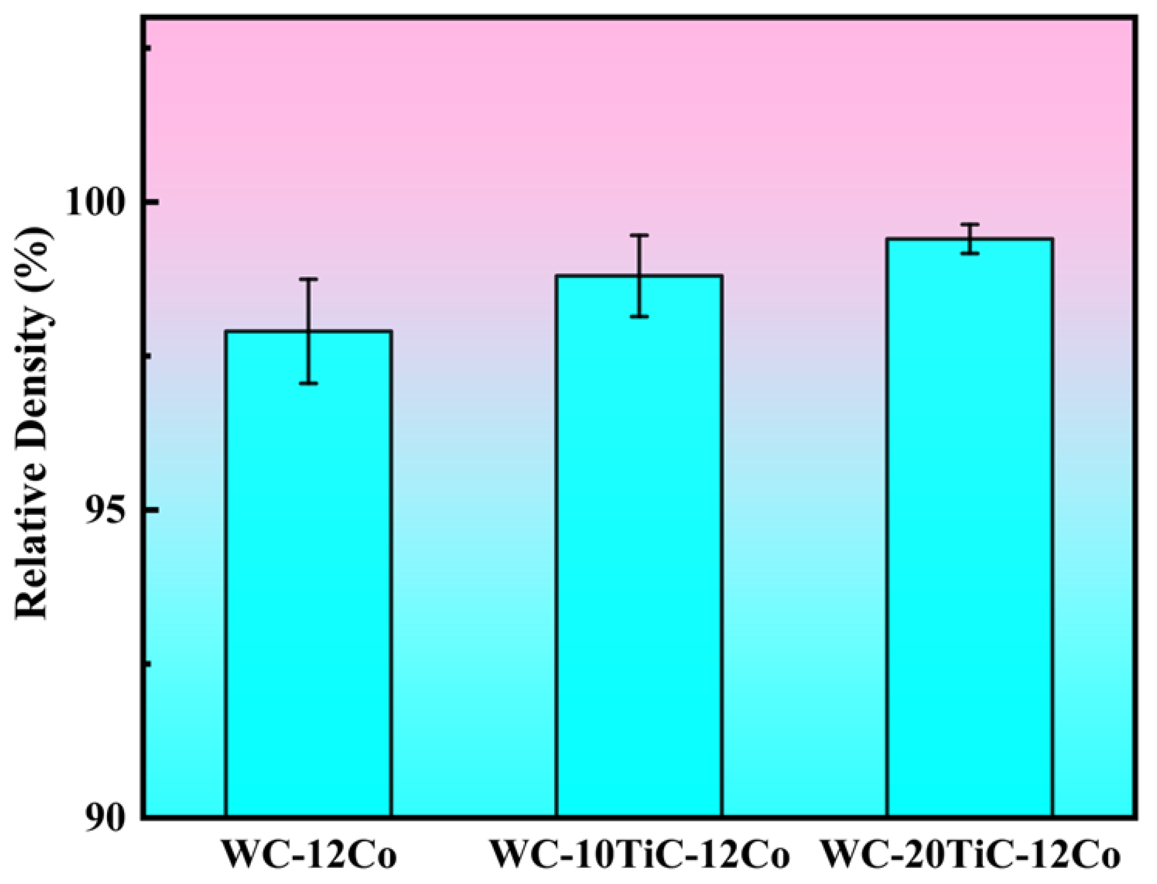
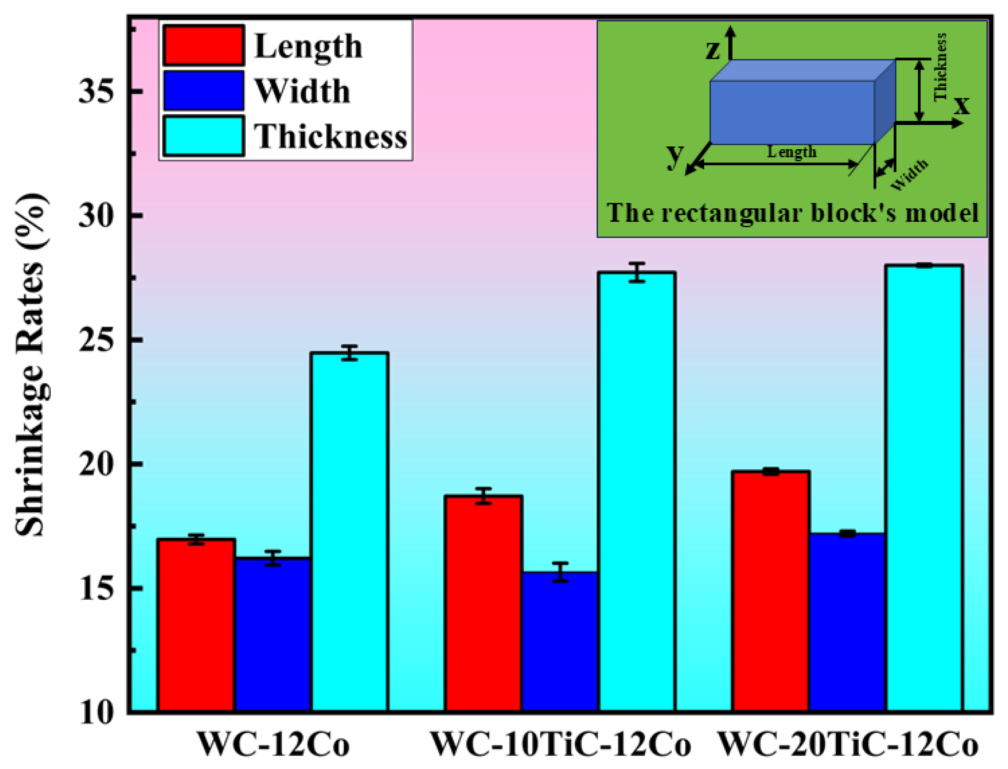
3.1. Relative Density and Dimensional Shrinkage

Cemented carbide samples (WC-12Co, WC-10TiC-12Co, and WC-20TiC-12Co) were fabricated using optimized printing parameters and a debinding-sintering process. As shown in Figure 4, all specimens exhibit relative densities exceeding 97%. A rigorous t-test of these results indicates that the relative density differences among these carbides are not statistically significant. These results confirm that the PEP processed carbides can achieve near-full density, demonstrating the feasibility of the printing-sintering process in this study.
After density evaluation, the dimensional shrinkage rates along different orientations were measured. A rectangular block with initial dimensions of 26 mm × 8.5 mm × 7 mm was designed and PEP processed with WC-xTiC-12Co carbides. The morphology of specimens after printing, degreasing, and sintering is shown in Figure 5. Relative to the model dimensions, the PEP-printed carbide components exhibit approximately 2% expansion along the x-axis, 8.5% expansion along the y-axis, and 4% contraction along the z-axis. This anisotropic dimensional change is attributed to the layer-by-layer deposition process in additive manufacturing. The extruded slurry, which retains some fluidity due to elevated temperature, preferentially flows along the X-Y plane. Simultaneously, limitations imposed by layer thickness and nozzle pressure lead to a lateral redistribution of excess material within the X-Y plane, as noted in reference [37]. This phenomenon, compounded by gravitational effects, results in dimensional changes characterized by expansion in the horizontal directions and contraction in the thickness direction.
After two-step debinding, dimensional changes of less than 0.2% have been observed. During the initial debinding phase, residual organic binders remain in the green body, with some acting as structural linkages and resulting in minimal shrinkage. In the secondary debinding phase, complete removal of the binders generates a porous structure. Although the pre-sintered green body shows moderate enhancement in mechanical strength, no significant shrinkage occurs at this stage.
Compared with debinding, sintering induces significantly greater shrinkage. The volumetric shrinkage rates of WC-12Co, WC-10TiC-12Co, and WC-20TiC-12Co are 44.1%, 50.4%, and 52.1%, respectively, relative to the STL model. As shown in Figure 6, the linear dimensional shrinkage rates increase with rising TiC content while remaining consistent across the same axes for all three carbides, highlighting the controllable anisotropic shrinkage of PEP-printed cemented carbides [38]. Due to the relatively loose interlayer stacking of the printed green body in the thickness direction, the most substantial shrinkage after sintering occurs in the z-direction. The measured z-axis shrinkage rates for WC-12Co, WC-10TiC-12Co, and WC-20TiC-12Co are 24.48%, 27.71%, and 28%, respectively.

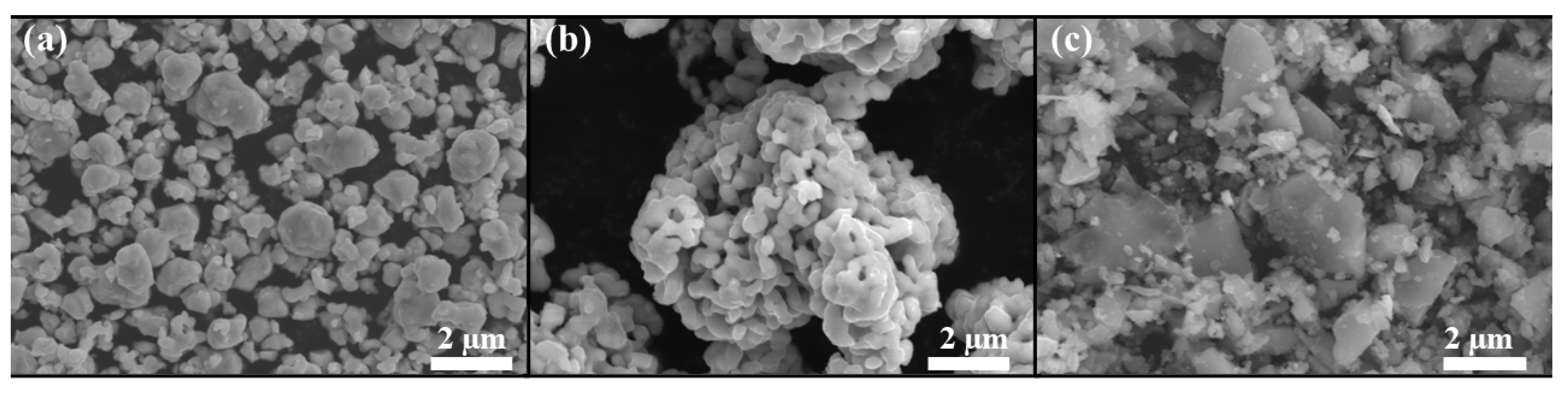
3.2. Microstructure Analysis

Organic binders used in extrusion-based additive manufacturing are typically macromolecular, often leaving carbon residues from incomplete debinding. This residual carbon can lead to the formation of free carbon phases after sintering [10]. Single-step debinding can easily leave residual carbon from the binder according to [39], introducing notable free carbon in the sintered samples. In contrast, a two-step debinding process employed in this study ensures the complete removal of organic binders, effectively suppressing the formation of free carbon during sintering based on references [10,32].
Figure 7 shows the XRD patterns of cemented carbides with varying TiC content. For WC-12Co, the primary phases detected are WC and Co. In WC-10TiC-12Co and WC-20TiC-12Co, the dominant phases are WC, TiC, and Co, with no evidence of carbon-deficient phases, free carbon, or other impurities. Despite identical processing parameters, variations in TiC content result in noticeable differences in surface phase composition, as indicated by fluctuations in TiC peak intensities. The XRD results confirm that the experimental protocol effectively controls residual carbon from the debinding process.
The cross-sectional microstructure of WC-xTiC-12Co cemented carbides is shown in Figure 8. After sintering, WC grains predominantly exhibited truncated triangular or triangular morphologies. The WC grain size distributions, analyzed using ImageJ software (ImageJ 1.x, U.S. National Institutes of Health, Bethesda, MD, USA), are shown in Figure 9, with median grain sizes (d50) summarized in Table 3. The WC grain sizes ranged from 0.87 to 0.98 μm, with only a small fraction exceeding 2 μm, indicating no significant abnormal grain growth. The increase of TiC content clearly reduces WC grain size to a notable degree, indicating the grain refinement effect of TiC.
Sintering is the most critical stage for microstructural evolution in cemented carbides, consisting of four stages: presintering, solid-state sintering, liquid-phase sintering, and cooling [40]. The liquid-phase sintering stage (above 1280 °C) dominates densification and porosity reduction while promoting WC grain growth via Ostwald ripening. In this stage, smaller WC grains dissolve in the liquid Co phase, and solute atoms diffuse toward larger WC grains due to their lower solubility. This dissolution-reprecipitation mechanism leads to WC grain coarsening and improved relative density [41].
As shown in Table 3, the average WC grain size decreased with increasing TiC content, demonstrating a strong correlation between TiC addition and grain refinement. TiC effectively suppresses both WC grain growth and abnormal coarsening of WC grains via restraining the dissolution-reprecipitation process of WC grains during liquid phase sintering [7,9,42].

3.3. Mechanical Properties

The Vickers hardness of cemented carbides with varying TiC content is shown in Figure 10. The hardness of WC-12Co, WC-10TiC-12Co, and WC-20TiC-12Co are 1317 HV30, 1403 HV30, and 1496 HV30, respectively. t-tests reveal that the Vickers hardness of the three cemented carbide formulations differs significantly between each pairwise comparison. The addition of TiC notably enhances the hardness due to the WC grain size refinement (Figure 9), which is consistent with the results in [9,43].
Figure 11 presents the three-point flexural strength test results. The flexural strength decreases from 2025 MPa to 915 MPa with the TiC content increasing from 0 to 20 wt.%. t-tests reveal a statistically significant difference in flexural strength between WC-12Co and WC-20TiC-12Co. This reduction is attributed to microstructural heterogeneities caused by TiC addition, which promote more significant stress concentration and the reduction of fracture toughness [9].
The tribological properties of sintered WC-12Co, WC-10TiC-12Co, and WC-20TiC-12Co were evaluated using Si3N4 balls as counterbodies. Figure 12a and Figure 12b show the friction coefficient and wear rate results, respectively. The average friction coefficients for WC-12Co, WC-10TiC-12Co, and WC-20TiC-12Co are 0.56, 0.51, and 0.47, while their corresponding wear rates were 91.828 × 10⁻⁶ mm3/(N·m), 77.843 × 10⁻⁶ mm3/(N·m), and 43.034 × 10⁻⁶ mm3/(N·m), respectively.
These results demonstrate that adding TiC not only reduces the friction coefficient but also significantly improves wear resistance. The wear rate decreases by 15.2% and 53.1% for 10 wt.% and 20 wt.% TiC additions, respectively, as compared with plain WC-12Co. This improvement is closely related to the increased hardness of TiC-containing carbides.
Figure 10, Figure 11 and Figure 12 illustrate the trade-off between hardness (wear resistance) and flexural strength in cemented carbides, a common trend across many grades. TiC addition enhances hardness and wear resistance, as it is harder than WC, but reduces toughness and ductility, leading to lower flexural strength in WC-TiC-Co carbides. To boost the flexural strength of TiC-containing carbides, strategies such as reducing particle size and applying post-sintering treatments like hot isostatic pressing (HIP) are recommended. Despite their lower flexural strength, WC-TiC-Co carbides offer advantages in oxidation resistance, wear resistance, and red hardness over plain WC-Co carbides, showing great potential in metal cutting, milling, and molding.

3.4. Cutting Performance

The cutting performance of PEP processed WC-xTiC-12Co carbide tools was evaluated through turning tests on HT250 bars (diameter: 30 mm) for 4 min and 8 min. The cutting parameters are listed in Table 4. Figure 13 illustrates the cutting process using the fabricated tools.
The assessment of tool wear was based on the measurement of flank wear depth, with a lower value indicating superior wear resistance. Figure 14 illustrates the wear morphologies of the tools after 4 and 8 min of cutting, as observed via a depth-of-field microscope. The results indicate that carbide tools incorporating TiC exhibit significantly reduced flank wear depths in comparison to the TiC-free WC-12Co tool. Figure 15 presents a quantitative comparison of the flank wear depth, as determined by ImageJ. The WC-12Co tool demonstrates wear depths of 0.783 mm after 4 min of cutting and 1.104 mm after 8 min. In contrast, the WC-10TiC-12Co tool shows wear depths of 0.524 mm and 0.574 mm, while the WC-20TiC-12Co tool exhibits the shallowest wear depths of 0.311 mm and 0.367 mm, after 4 and 8 min of cutting, respectively. Figure 14 and Figure 15 clearly demonstrate that the cutting performance improves more significantly with higher TiC content as the cutting test duration increases. The flank wear progression typically occurs in three stages: initial wear, normal wear, and severe wear [44]. In WC-12Co, the wear depth increases significantly from 0.783 mm (4 min of cutting) to 1.104 mm (8 min of cutting), indicating a rapid transition to the severe wear stage. In contrast, WC-10TiC-12Co and WC-20TiC-12Co show minimal differences in wear depth between 4 min (0.524 mm and 0.311 mm) and 8 min (0.574 mm and 0.367 mm), suggesting a delayed onset of severe wear and prolonged normal wear stages. This effect, driven by TiC addition, enhances tool durability.
Table 5 summarizes the main properties of WC-xTiC-12Co carbide. The enhanced flank wear resistance is ascribed to the augmented hardness and elevated relative density of TiC-bearing carbides. In particular, WC-20TiC-12Co, attaining the highest hardness and a relative density of 99.4%, demonstrates the most outstanding wear resistance. This underscores the importance of densification in optimizing tribological performance [45].
The material composition of cutting tools, in addition to affecting flank wear resistance, also plays a crucial role in determining the surface quality of the workpiece. Figure 16 and Figure 17 present the 3D and 2D surface roughness profiles of machined HT250, as measured by a roughness tester. Table 6 summarizes the surface roughness parameters for cutting duration of 4 and 8 min. After 4 min of cutting, the Ra values of the HT250 workpiece machined with WC-12Co, WC-10TiC-12Co, and WC-20TiC-12Co are 0.847 µm, 0.789 µm, and 0.846 µm, respectively. After 8 min of cutting, these values decrease to 0.736 µm, 0.644 µm, and 0.638 µm, respectively. Similarly, the Rz values exhibit a comparable trend. The higher surface roughness observed at 4 min compared to 8 min is linked to the initial wear stage of the cutting tools, where rapid tool wear and variable friction coefficients are dominant. In contrast, during longer cutting durations, the surface roughness exhibits a downward trend (Table 6), as all tools transition into a steady-state friction regime with stabilized wear rates [44].

4. Conclusions

This study investigated the microstructure and mechanical behavior of WC-12Co cemented carbides with varying TiC contents, fabricated via PEP additive manufacturing. The effects of TiC content on relative density, shrinkage, microstructure, mechanical properties, and cutting performance were systematically analyzed. The key findings are as follows:
(1)
The PEP additive manufacturing process has been successfully utilized to fabricate high-density cemented carbides with high TiC contents. The PEP-processed WC-12Co, WC-10TiC-12Co, and WC-20TiC-12Co achieves relative densities of 97.9%, 98.8%, and 99.4%, respectively. The average linear shrinkage rates upon sintering are 14.9–19.7%, 13.1–17.2%, and 24.4–28.0% along the x, y, and z axes, respectively, indicating controllable dimensional changes.
(2)
The addition of TiC refines the WC grain size. The average WC grain size for WC-12Co carbides with 10 wt.% and 20 wt.% TiC are 0.88 μm and 0.87 μm, respectively, compared to 0.98 μm for TiC-free WC-12Co.
(3)
The hardness of the PEP processed carbides increases with TiC content, with the maximum Vickers hardness augmented by approximately 13.6% for WC-20TiC-12Co over WC-12Co. However, TiC addition decreases flexural strength apparently. Tribological testing reveals the friction coefficient decreases while wear resistance increases with TiC content.
(4)
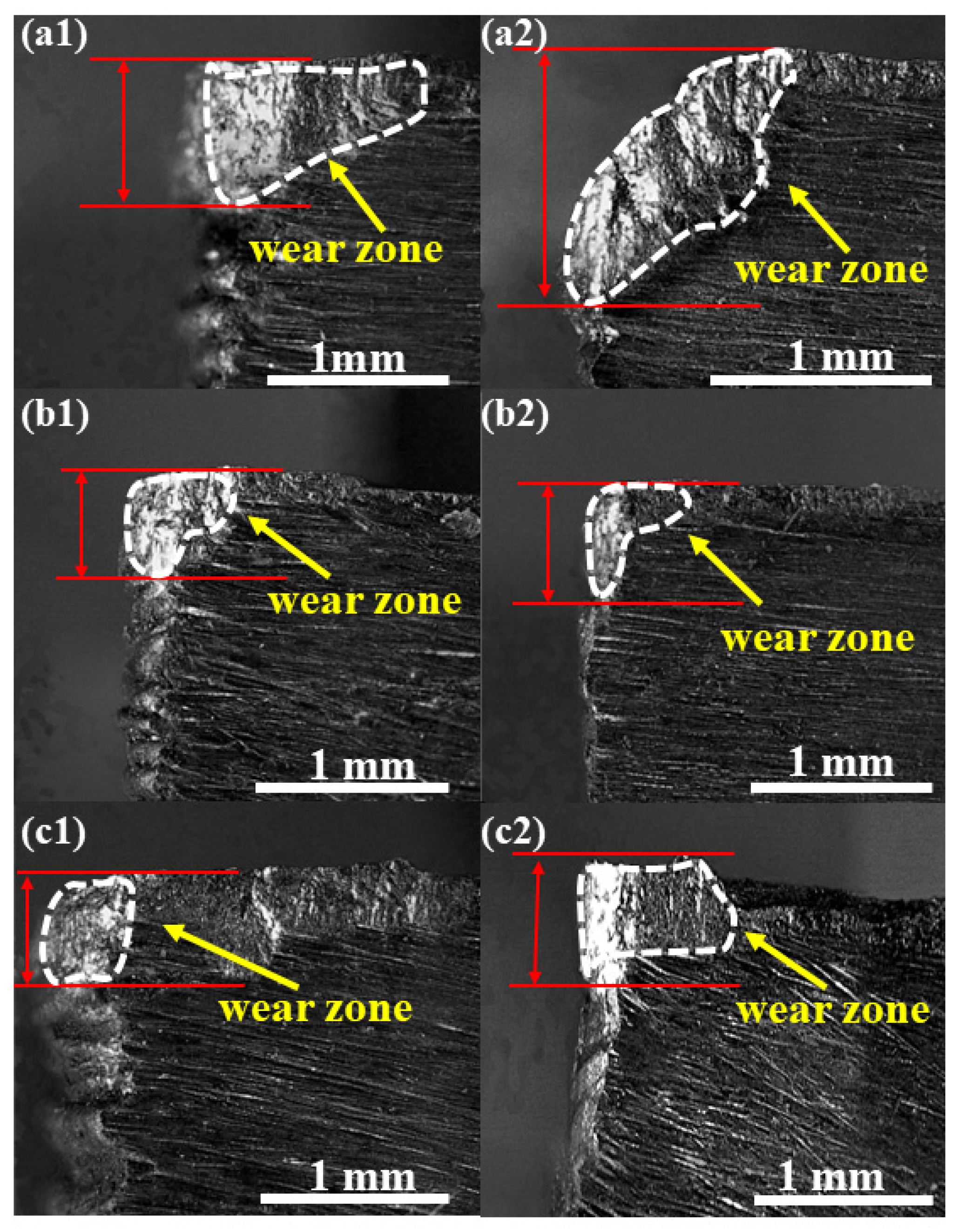
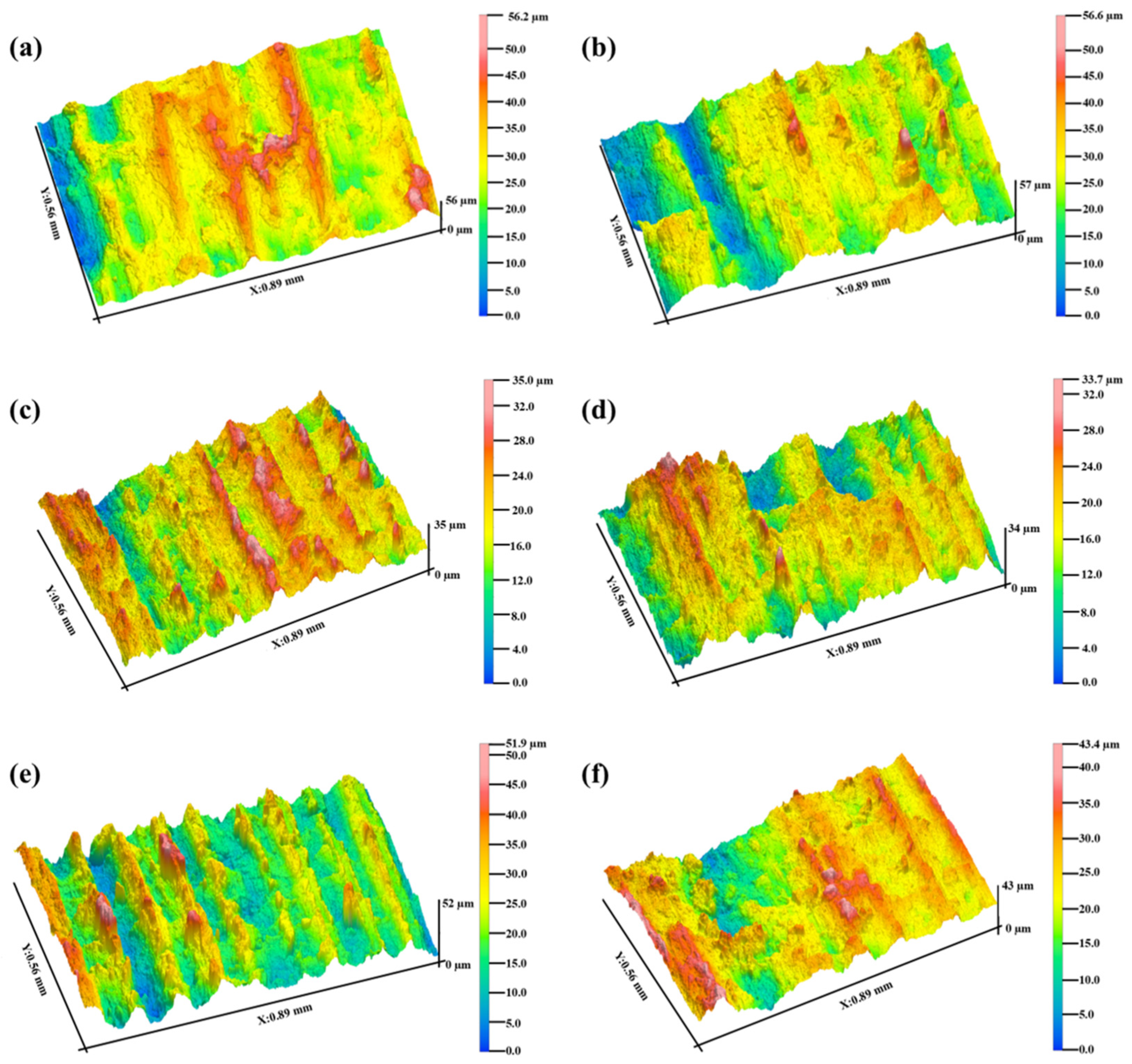
The TiC addition significantly enhances wear resistance of PEP processed carbides during HT250 cutting test and reduces the workpiece surface roughness. The beneficial role of TiC in improving cutting performance is more evident for longer cutting durations.
(5)
Overall, PEP-processed TiC-containing carbides show promising properties, indicating significant industrial potential in metal cutting, milling, and molding. Future research on PEP-processed cemented carbides could focus on optimizing carbide particle size, designing organic binder materials, developing TaC/NbC-containing carbides, and exploring advanced sintering techniques like microwave sintering. Additionally, creating cutting tools with more complex geometries is another potential research direction.

Author Contributions

Conceptualization, X.D. and P.N.; methodology, B.Z.; formal analysis, B.Z.; investigation, D.H.; resources, X.D.; data curation, P.N.; writing—original draft preparation, B.Z.; writing—review and editing, X.D. and P.N.; visualization, B.Z.; supervision, X.D.; project administration, P.N.; funding acquisition, X.D. and P.N. All authors have read and agreed to the published version of the manuscript.

Funding

This research was supported by program for scientific research start-up funds of Guangdong Ocean University (Grant No. 060302062403) and Guangdong Ocean University Undergraduate Innovation Team Project “3D Printing Innovation Team” (Grant No. CXTD2019007).

Data Availability Statement

The original contributions presented in this study are included in the article. Further inquiries can be directed to the corresponding author.

Conflicts of Interest

The authors declare no conflicts of interest.

References

  1. Petersson, A.; Ågren, J. Rearrangement and Pore Size Evolution during WC–Co Sintering below the Eutectic Temperature. Acta Mater. 2005, 53, 1673–1683. [Google Scholar] [CrossRef]
  2. Liu, X.; Song, X.; Wang, H.; Liu, X.; Tang, F.; Lu, H. Complexions in WC–Co Cemented Carbides. Acta Mater. 2018, 149, 164–178. [Google Scholar] [CrossRef]
  3. Miao, H.U.; Tang, J.; Chen, X.; Nan, Y.E.; Zhao, X.Y.; Xu, M.M. Microstructure and Properties of WC-12Co Composite Coatings Prepared by Laser Cladding. Trans. Nonferrous Met. Soc. China 2020, 30, 1017–1030. [Google Scholar]
  4. Yang, Q.; Deng, D.; Li, J.; Chen, L.; Guo, S.; Liu, J.; Chen, H. Fabrication and Mechanical Properties of WC–10Co Cemented Carbides with Plate-Like WC Grains. J. Alloys Compd. 2019, 803, 860–865. [Google Scholar] [CrossRef]
  5. Ma, M.; Diao, Y.; Wang, K.; Zhou, X.; Li, G.; Wang, Q. Nanocrystalline Microstructure Enhanced Mechanical Properties and Cutting Performance of WC–10Co–Ti (C, N) Gradient Cemented Carbides. Mater. Charact. 2024, 209, 113708. [Google Scholar] [CrossRef]
  6. Heydari, L.; Lietor, P.F.; Corpas-Iglesias, F.A.; Laguna, O.H. Ti (C,N) and WC-Based Cermets: A Review of Synthesis, Properties, and Applications in Additive Manufacturing. Materials 2021, 14, 6786. [Google Scholar] [CrossRef]
  7. Xiong, J.; Guo, Z.; Yang, M.; Wan, W.; Dong, G. Tool Life and Wear of WC–TiC–Co Ultrafine Cemented Carbide during Dry Cutting of AISI H13 Steel. Ceram. Int. 2013, 39, 337–346. [Google Scholar] [CrossRef]
  8. Petersson, A. Sintering Shrinkage of WC–Co and WC–(Ti, W)C–Co Materials with Different Carbon Contents. Int. J. Refract. Met. Hard Mater. 2004, 22, 211–217. [Google Scholar] [CrossRef]
  9. Lee, K.H.; Cha, S.I.; Kim, B.K.; Hong, S.H. Effect of WC/TiC Grain Size Ratio on Microstructure and Mechanical Properties of WC–TiC–Co Cemented Carbides. Int. J. Refract. Met. Hard Mater. 2006, 24, 109–114. [Google Scholar] [CrossRef]
  10. Chen, C.; Huang, B.; Liu, Z.; Li, Y.; Zou, D.; Liu, T.; Chang, Y.; Chen, L. Additive Manufacturing of WC–Co Cemented Carbides: Process, Microstructure, and Mechanical Properties. Addit. Manuf. 2023, 63, 103410. [Google Scholar] [CrossRef]
  11. Lakhdar, Y.; Tuck, C.; Binner, J.; Terry, A.; Goodridge, R. Additive Manufacturing of Advanced Ceramic Materials. Prog. Mater. Sci. 2021, 116, 100736. [Google Scholar] [CrossRef]
  12. Domashenkov, A.; Borbély, A.; Smurov, I. Structural Modifications of WC–Co Nanophased and Conventional Powders Processed by Selective Laser Melting. Mater. Manuf. Processes 2017, 32, 93–100. [Google Scholar] [CrossRef]
  13. Liu, J.; Chen, J.; Zhou, L.; Liu, B.; Lu, Y.; Wu, S.; Deng, X.; Lu, Z.; Xie, Z.; Liu, W.; et al. Role of Co Content on Densification and Microstructure of WC–Co Cemented Carbides Prepared by Selective Laser Melting. Acta Metall. Sin. (Engl. Lett.) 2021, 34, 1245–1254. [Google Scholar] [CrossRef]
  14. Konyashina, I.; Hinnersa, H.; Riesa, B.; Kirchner, A.; Kloeden, B.; Kieback, B.; Nilen, R.W.N.; Sidorenko, D. Additive Manufacturing of WC–13%Co by Selective Electron Beam Melting: Achievements and Challenges. Int. J. Refract. Met. Hard Mater. 2019, 84, 105028. [Google Scholar] [CrossRef]
  15. Wang, J.; Han, Y.; Zhao, Y.; Li, X.; Yi, D.; Guo, Z.; Cao, Y.; Liu, B.; Tang, H.P. Microstructure and Properties of WC–12Co Cemented Carbide Fabricated via Selective Electron Beam Melting. Int. J. Refract. Met. Hard Mater. 2022, 106, 105847. [Google Scholar] [CrossRef]
  16. Wang, X.C.; Laoui, T.; Bonse, J.; Kruth, J.P.; Lauwers, B.; Froyen, L. Direct Selective Laser Sintering of Hard Metal Powders: Experimental Study and Simulation. Int. J. Adv. Manuf. Technol. 2002, 19, 351–357. [Google Scholar] [CrossRef]
  17. Kruth, J.P.; Wang, X.; Laoui, T.; Froyen, L. Lasers and Materials in Selective Laser Sintering. Assem. Autom. 2003, 23, 357–371. [Google Scholar] [CrossRef]
  18. Kumar, S. Manufacturing of WC–Co Moulds Using SLS Machine. J. Mater. Process. Technol. 2009, 209, 3840–3848. [Google Scholar] [CrossRef]
  19. Kumar, S.; Czekanski, A. Optimization of Parameters for SLS of WC–Co. Rapid Prototyp. J. 2017, 23, 1202–1211. [Google Scholar] [CrossRef]
  20. Enneti, R.K.; Prough, K.C.; Wolfe, T.A.; Klein, A.; Studley, N.; Trasorras, J.L. Sintering of WC–12%Co Processed by Binder Jet 3D Printing (BJ3DP) Technology. Int. J. Refract. Met. Hard Mater. 2018, 71, 28–35. [Google Scholar] [CrossRef]
  21. Ren, X.; Shao, H.; Lin, T.; Zheng, H. 3D Gel-Printing—An Additive Manufacturing Method for Producing Complex Shape Parts. Mater. Des. 2016, 101, 80–87. [Google Scholar] [CrossRef]
  22. Kim, H.; Kim, J.I.; Kim, Y.D.; Jeong, H.; Ryu, S.S. Material Extrusion-Based Three-Dimensional Printing of WC–Co Alloy with a Paste Prepared by Powder Coating. Addit. Manuf. 2022, 52, 102679. [Google Scholar] [CrossRef]
  23. Zakeri, S.; Vippola, M.; Levänen, E. A Comprehensive Review of the Photopolymerization of Ceramic Resins Used in Stereolithography. Addit. Manuf. 2020, 35, 101177. [Google Scholar] [CrossRef]
  24. Yakubov, V.; Ostergaard, H.; Bhagavath, S.; Leung, C.L.A.; Hughes, J.; Yasa, E.; Khezri, M.; Löschke, S.M.; Li, Q.; Paradowska, A.M. Recycled Aluminium Feedstock in Metal Additive Manufacturing: A State of the Art Review. Heliyon 2024, 10, e25252. [Google Scholar] [CrossRef] [PubMed]
  25. Morshed-Behbahani, K.; Aliyu, A.; Bishop, D.P.; Nasiri, A. Additive Manufacturing of Copper-Based Alloys for High-Temperature Aerospace Applications: A Review. Mater. Today Commun. 2024, 38, 108395. [Google Scholar] [CrossRef]
  26. Sun, H.; Zou, B.; Wang, X.; Chen, W.; Zhang, G.; Quan, T.; Huang, C. Advancements in Multi-Material Additive Manufacturing of Advanced Ceramics: A Review of Strategies, Techniques and Equipment. Mater. Chem. Phys. 2024, 314, 129337. [Google Scholar] [CrossRef]
  27. Li, X.; Su, H.; Dong, D.; Zhao, D.; Liu, Y.; Shen, Z.; Jiang, H.; Guo, Y.; Liu, H.; Fan, G.; et al. Enhanced Comprehensive Properties of Stereolithography 3D Printed Alumina Ceramic Cores with High Porosities by a Powder Gradation Design. J. Mater. Sci. Technol. 2022, 131, 264–275. [Google Scholar] [CrossRef]
  28. An, S.; Foest, R.; Fricke, K.; Riemer, H.; Fröhlich, M.; Quade, A.; Schäfer, J.; Weltmann, K.; Kersten, H. Pretreatment of Cutting Tools by Plasma Electrolytic Polishing (PEP) for Enhanced Adhesion of Hard Coatings. Surf. Coat. Technol. 2021, 405, 126504. [Google Scholar] [CrossRef]
  29. Chen, C.; Huang, B.; Liu, Z.; Chen, L.; Li, Y.; Zou, D.; Chang, Y.; Cheng, X.; Zhou, R.; Liu, Y. Material Extrusion Additive Manufacturing of WC–9Co Cemented Carbide. Addit. Manuf. 2024, 86, 104203. [Google Scholar] [CrossRef]
  30. Zhao, Z.; Liu, R.T.; Chen, J.; Xiong, X. Carbon Control and Densification of WC–8%Co Fabricated by Extrusion-Based Additive Manufacturing under Pressureless Sintering. Mater. Today Commun. 2023, 36, 106866. [Google Scholar] [CrossRef]
  31. Zhao, Z.; Liu, R.T.; Chen, J.; Xiong, X. Material Extrusion Printing of WC–8%Co Cemented Carbide Based on Partly Water-Soluble Binder and Post-Processing. J. Mater. Res. Technol. 2024, 29, 4394–4405. [Google Scholar] [CrossRef]
  32. Lu, T.X.; Meng, X.Y.; Li, S.D.; Deng, X. Additive Manufacturing Process and Microstructure during Powder Extrusion Printing of Cemented Carbides. J. Mater. Eng. 2022, 50, 147–155. [Google Scholar]
  33. ASTM C373-18; Standard Test Methods for Determination of Water Absorption and Associated Properties by Vacuum Method for Pressed Ceramic Tiles and Glass Tiles and Boil Method for Extruded Ceramic Tiles and Non-tile Fired Ceramic Whiteware Products. ASTM International: West Conshohocken, PA, USA, 2018.
  34. ISO 25178:2012; Geometrical Product Specifications (GPS)—Surface Texture: Areal. International Organization for Standardization: Geneva, Switzerland, 2012.
  35. ASTM E384-22; Standard Test Method for Microindentation Hardness of Materials. ASTM International: West Conshohocken, PA, USA, 2022.
  36. ASTM A370-24a; Standard Test Methods and Definitions for Mechanical Testing of Steel Products. ASTM International: West Conshohocken, PA, USA, 2024.
  37. Zhang, W.; Liu, Y.; Wu, J.; Liu, Y.; Zhu, X.; Luo, Y.; Li, L.; Huang, L. Control Morphology and Properties in Additive Manufacturing of Functional Gradient Cemented Carbides for Polycrystalline Diamond Substrates. Int. J. Refract. Met. Hard Mater. 2024, 118, 106445. [Google Scholar] [CrossRef]
  38. Ait-Mansour, I.; Kretzschmar, N.; Chekurov, S.; Salmi, M.; Rech, J. Design-Dependent Shrinkage Compensation Modeling and Mechanical Property Targeting of Metal FFF. Prog. Addit. Manuf. 2020, 5, 51–57. [Google Scholar] [CrossRef]
  39. Mariani, M.; Goncharov, I.; Mariani, D.; De Gaudenzi, G.P.; Popovich, A.; Lecis, N.; Vedani, M. Mechanical and Microstructural Characterization of WC–Co Consolidated by Binder Jetting Additive Manufacturing. Int. J. Refract. Met. Hard Mater. 2021, 100, 105639. [Google Scholar] [CrossRef]
  40. García, J.; Ciprés, V.C.; Blomqvist, A.; Kaplan, B. Cemented Carbide Microstructures: A Review. Int. J. Refract. Met. Hard Mater. 2019, 80, 40–68. [Google Scholar] [CrossRef]
  41. Sun, L.; Jia, C.C.; Xian, M. A Research on the Grain Growth of WC–Co Cemented Carbide. Int. J. Refract. Met. Hard Mater. 2007, 25, 121–124. [Google Scholar] [CrossRef]
  42. Luo, R.; Chen, N.; Xiong, H.; Li, Z. Microhomogeneous WC–TiC–Co Composite Powders with Enhanced Sinterability via a Two-Step Carburization Method. Int. J. Refract. Met. Hard Mater. 2021, 95, 105413. [Google Scholar] [CrossRef]
  43. Lamim, J.D.; de Oliveira, H.C.P.; Batista, A.C.; Guimarães, R.S.; Filgueira, M. Use of Ti in Hard Metal Alloys–Part II: Mechanical Properties. Mater. Wiss. Werkst. 2010, 41, 666–669. [Google Scholar] [CrossRef]
  44. Diniz, A.E.; Machado, Á.R.; Corrêa, J.G. Tool Wear Mechanisms in the Machining of Steels and Stainless Steels. Int. J. Adv. Manuf. Technol. 2016, 87, 3157–3168. [Google Scholar] [CrossRef]
  45. Liu, B.; Zhao, H.; Li, X.; Yang, Z.; Zhang, D.; Liu, Z. Effect of Pore Structure on the Thermophysical and Frictional Properties of High-Density Graphite. Microporous Mesoporous Mater. 2022, 330, 111613. [Google Scholar] [CrossRef]
Figure 1. Morphology of the feedstock powders used in this study: (a) WC, (b) Co, and (c) TiC.
Metals 15 00561 g001
Figure 2. PEP printing process for cemented carbide preparation: (a) initial powder preparation, (b) PEP forming, and (c) debinding and sintering.
Metals 15 00561 g002
Figure 3. The debinding and sintering curves for WC-xTiC-12Co carbide green parts, (a) debinding and presintering curve, and (b) sinter-hip curve.
Metals 15 00561 g003
Figure 4. Relative density of WC-TiC-12Co carbide with different TiC contents.
Metals 15 00561 g004
Figure 5. Morphology of WC-xTiC-12Co carbide after printing, debinding, and sintering: (a1a3) WC-12Co, (b1b3) WC-10TiC-12Co, (c1c3) WC-20TiC-12Co.
Metals 15 00561 g005
Figure 6. Linear dimensional shrinkage rates of WC-xTiC-12Co carbides upon sintering.
Metals 15 00561 g006
Figure 7. X-ray diffraction spectra of WC-xTiC-12Co cemented carbide surfaces.
Metals 15 00561 g007
Figure 8. Microstructure of WC-xTiC-12Co cemented carbides after sintering: (a) WC-12Co, (b) WC-10TiC-12Co, and (c) WC-20TiC-12Co.
Metals 15 00561 g008
Figure 9. WC grain size distribution of sintered carbides: (a) WC-12Co, (b) WC-10TiC-12Co, and (c) WC-20TiC-12Co.
Metals 15 00561 g009
Figure 10. Average hardness of the sintered WC-xTiC-12Co carbides. *** p ≤ 0.001.
Metals 15 00561 g010
Figure 11. Flexural strength of the sintered carbides. * p ≤ 0.05.
Metals 15 00561 g011
Figure 12. Friction and wear experiment: (a) friction coefficient curves and (b) wear rate.
Metals 15 00561 g012
Figure 13. Cutting process of PEP processed WC-xTiC-12Co carbide tools: (a) cutting test configuration; (b) geometrical characteristics of the fabricated tools.
Metals 15 00561 g013
Figure 14. Flank wear morphologies of WC-xTiC-12Co carbide after 4 min and 8 min of cutting: (a1) WC-12Co, 4 min; (a2) WC-12Co, 8 min; (b1) WC-10TiC-12Co, 4 min; (b2) WC-10TiC-12Co, 8 min; (c1) WC-20TiC-12Co, 4 min; (c2) WC-20TiC-12Co, 8 min.
Metals 15 00561 g014
Figure 15. WC-xTiC-12Co carbide tool flank wear comparison.
Metals 15 00561 g015
Figure 16. 3D surface morphology of HT250 after cutting: (a) WC-12Co, 4 min; (b) WC-10TiC-12Co, 4 min; (c) WC-20TiC-12Co, 4 min; (d) WC-12Co, 8 min; (e) WC-10TiC-12Co, 8 min; (f) WC-20TiC-12Co, 8 min.
Metals 15 00561 g016
Figure 17. 2D surface roughness profiles of HT250 after cutting.
Metals 15 00561 g017
Table 1. Composition of WC-xTiC-12Co.
SampleWC-12CoWC-10TiC-12CoWC-20TiC-12Co
WC (wt.%)887868
TiC (wt.%)01020
Co (wt.%)121212
Table 2. Main PEP processing parameters in this study.
Nozzle
Temperature (°C)
Build Plate Temperature (°C)Printing Speed
(mm/s)
Layer
Thickness (mm)
Layer
Thickness (mm)
Flow Rate
(%)
16590100.20.685
Table 3. Average WC grain size of WC-xTiC-12Co carbides.
SampleWC-12CoWC-10TiC-12CoWC-20TiC-12Co
d50 (μm)0.980.880.87
Table 4. Main cutting parameters for WC-xTiC-12Co carbide cutting HT250.
Main Cutting
Parameters
Cutting Speed
(m/min)
Cutting Speed
(mm)
Feed Rate
(mm/min)
Values47.11.650
Table 5. Mechanical testing summary for WC-xTiC-12Co carbides.
SampleUnitWC-12CoWC-10TiC-12CoWC-20TiC-12Co
Relative density%97.998.899.4
HardnessHV30131714031496
Flexural strengthMPa20251434915
Friction coefficient 0.560.510.47
Tribological Test: Wear ratemm3/(N·m)91.828 × 10−677.843 × 10−643.034 × 10⁻⁶
Cutting Test: Wear value/4 minmm0.7830.5240.311
Cutting Test: Wear value/8 minmm1.1040.5740.367
Table 6. Surface roughness parameters of HT250 after cutting test for different cutting duration.
ParameterUnitWC-12CoWC-10TiC-12CoWC-20TiC-12Co
4 min8 min4 min8 min4 min8 min
Raµm0.8470.7360.7890.6440.8460.638
Rzµm5.3235.0404.4023.8385.6124.187
Rsk −0.0660.0290.152−0.013−0.0580.083
Rku 3.9932.8042.8783.0823.0563.714
Disclaimer/Publisher’s Note: The statements, opinions and data contained in all publications are solely those of the individual author(s) and contributor(s) and not of MDPI and/or the editor(s). MDPI and/or the editor(s) disclaim responsibility for any injury to people or property resulting from any ideas, methods, instructions or products referred to in the content.

