Review

Analysis of Friction Stir Welding of Aluminum Alloys

1
Mechanics, Mechatronics and Materials (3M) Laboratory, National School of Applied Sciences ENSA, Abdelmalek Essaadi University, Tetouan 93030, Morocco
2
Department of Engineering, University of Messina, Contrada di Dio, 98166 Messina, Italy
*
Author to whom correspondence should be addressed.
Metals 2025, 15(5), 532; https://doi.org/10.3390/met15050532
Submission received: 21 March 2025 / Revised: 23 April 2025 / Accepted: 7 May 2025 / Published: 9 May 2025
(This article belongs to the Section Welding and Joining)

Abstract

Friction Stir Welding (FSW) is a solid-state joining technique that has gained widespread adoption, particularly for aluminum alloys, due to its ability to produce high-quality welds without melting base materials. This comprehensive review focuses on the influence of process parameters on weld characteristics and performance. Compared to conventional fusion welding methods, FSW offers notable advantages, including superior mechanical properties, fewer defects, enhanced corrosion resistance, and lower environmental impact. The review also addresses key challenges such as tool wear, precise process control, and complications arising from welding dissimilar alloys. By synthesizing recent developments and case studies, this work outlines current limitations and proposes future directions for optimizing the FSW process to expand its applicability in critical engineering sectors.

1. Introduction

Friction Stir Welding is a solid joining technique utilized primarily for nonferrous components such as aluminum alloys. This state-of-the-art innovation addresses the inherent gap associated with conventional welding methods by avoiding defect zones, reducing thermal distortion, and preventing filler-melting issues. The increased demand for materials with improved mechanical properties, such as increased hardness and reduced density, has further propelled innovation within the light metals and composite sectors, such as aerospace, automobile, train, and ship construction, and electronics [1]. Due to its lightness, corrosion resistance, and high heat conduction capacity, aluminum is one of the primary light metal materials [2]. For improvements in fuel efficiency, the automotive industry is turning to the immediate replacement of steel engines with lighter aluminum alternatives. This upgrade is particularly significant given the crowded global market and tighter government controls resulting from climate change. Consequently, the number of studies on FSW has increased significantly in recent years, including the number of publications, with numerous attempts to address issues such enhancing mechanical characteristics and reducing defect possibilities [3].
A variety of FSW feasibility analyses are performed in this study. The first is an investigation of the consequences of variable formulations in modeling based on empirical and theoretical experimental analyses. The transmission of friction and heat during the FSW method is shown. Material and simulation processing conservatism are identified as issues to be addressed to keep the resulting deflections within controlled dimensions. A comprehensive understanding of FSW must account for both the microstructural and macroscopic physical conditions that influence material properties and adaptability [4]. This review evaluates the evolution of mechanical properties in aluminum welds, with particular focus on recent advancements achieved through FSW techniques.
These determinations are related to an overarching design, which includes an analytical cost examination, and they can be considered in a larger context. The 6061-T6 and 5083-H116 triple-weld double-sided friction welding methods were investigated, and a migration process was implemented. Considerable differences existed between nano- and macro-hardness, grain composition, phases, and substructure due to the distinct welding processes. By gradually changing tensile stress development over a long time, the 6061-T6 method demonstrated no off-normal yield or fine recrystallization. Longer fracture lifecycles were discovered with duplex joints [5].
This study enhances the understanding of FSW by systematically analyzing how process parameters affect the mechanical and metallurgical behavior of aluminum alloys. Different welding configurations were analyzed to assess their individual and combined effects on joint performance [6].

2. Historical Development of Friction Stir Welding

In 1991, the invention of Friction Stir Welding (FSW) for aluminum was announced at an international symposium. FSW was initially met with skepticism because, to many, it defied the conventional wisdom of welding. Over the years, FSW advancement has benefited from an increase in technological capacity and improvements in fundamental understanding. The initial application has also broadened considerably with commercial success, with licensed equipment being used most notably by transportation manufacturers around the globe. Finally, industry and academia agreed in the late 1990s that scientific research was of crucial importance in the early stages of a new technology [7].
There were significant positive signs from basic research, driven by academic curiosity, by researchers seeking to break new ground. In the years that followed, several different aluminum joining modes emerged, and research efforts turned to increasing the basic understanding of FSW. Funded research was conducted worldwide, and important contributions were made in several key application areas [8]. The mechanics of twist extrusion, proposed in the mid-1980s, served as a conceptual precursor to the development of FSW. FSW’s technological maturity is now well established, enabling its adoption across diverse sectors including defense, the automotive industry, and commercial and specialized transportation. The new technology has found a range of interesting and cost-effective applications in each of these areas. While major technological advancements emerged in the 1990s, parallel efforts focused on expanding application potential through material property research and development [9].
Ongoing research continues to address FSW’s challenges, with numerous case studies demonstrating its increasing promise for practical engineering applications. With many recent papers reporting impressive outcomes, it is clear that interest in using FSW on a commercial scale is on the rise [10].

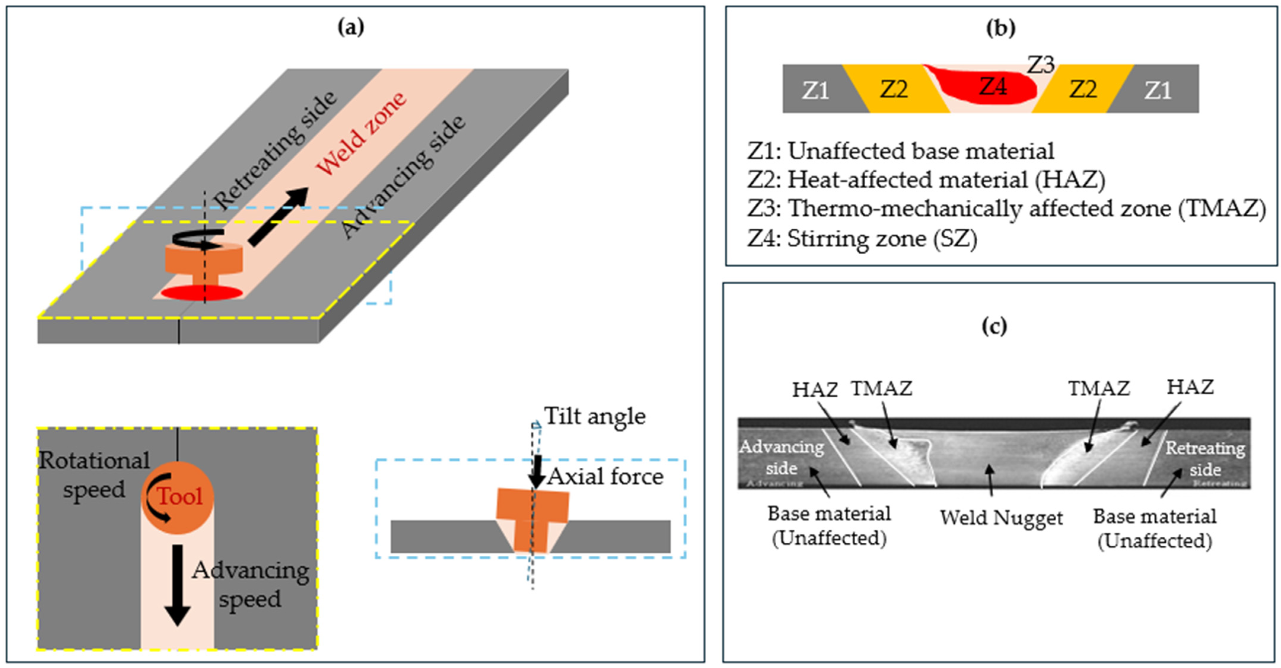
3. Principles and Mechanisms of Friction Stir Welding

The Friction Stir Welding (FSW) process is a solid-state joining technique wherein a rotating non-consumable tool is plunged into the abutted interface of two workpieces, typically plates or sheets, generating sufficient heat to plastically deform and mix the materials without melting [11]. As illustrated in Figure 1a, the rotating tool generates frictional heat at the tool–workpiece interface, softening the material into a plastic state and enabling its mechanical stirring within the weld zone. This process gives rise to distinct microstructural regions: the Stir Zone (SZ), where intense plastic deformation and dynamic recrystallization occur; the thermo-mechanically affected zone (TMAZ), where the material experiences elevated temperatures and plastic strain but no recrystallization; and the heat-affected zone (HAZ), which undergoes thermal exposure without significant plastic deformation [12] (see Figure 1b,c).
Material flow during FSW is governed by the tool geometry, process parameters, and thermomechanical properties of base materials. Key influencing factors include the tool’s shoulder and pin shape, rotational speed, traverse speed, tilt angle, axial force, and the interaction between these variables and the flow behavior of the plasticized material [13]. Among these, heat generation is of paramount importance, as it dictates the extent of plastic deformation, material mixing, and subsequent metallurgical transformations.
Heat generation in FSW primarily results from two mechanisms: frictional heating at the interface between the tool and workpiece, and plastic deformation heating within the stirred material. Approximately 90% of the heat is produced at the shoulder–workpiece interface due to its larger contact area and normal force, while the remaining 10% arises near the pin, where high shear deformation occurs [13,15]. This can be quantified using the following frictional heat equation [16]:
Q F r i c t i o n = μ · F · ω · r
where μ is the friction coefficient, F is the normal force, ω is the angular velocity (rotational speed), and r is the radius of the tool’s shoulder.
Heat from plastic deformation is similarly characterized by [17]
Q P l a s t i c = η · σ · ε
where η is the efficiency factor (typically 0.8–0.95), σ is the material flow stress, and ε is the strain rate during deformation.
Recent studies have advanced the modeling of these phenomena, incorporating coupled thermomechanical simulations to capture transient temperature fields and material-softening behavior more accurately [18]. Understanding the relative contribution of frictional and deformation-induced heating is essential for optimizing weld quality, particularly in high-strength aluminum alloys sensitive to heat input.
The magnitude and distribution of heat generation directly influence dynamic recrystallization behavior in the stir zone, ultimately affecting grain morphology, residual stresses, and joint performance
Ultimately, the spatial distribution and magnitude of heat generation critically affect elements of microstructural evolution such as grain refinement, phase dissolution, and dynamic recrystallization within the stir zone, thereby determining the mechanical performance and integrity of the welded joint.

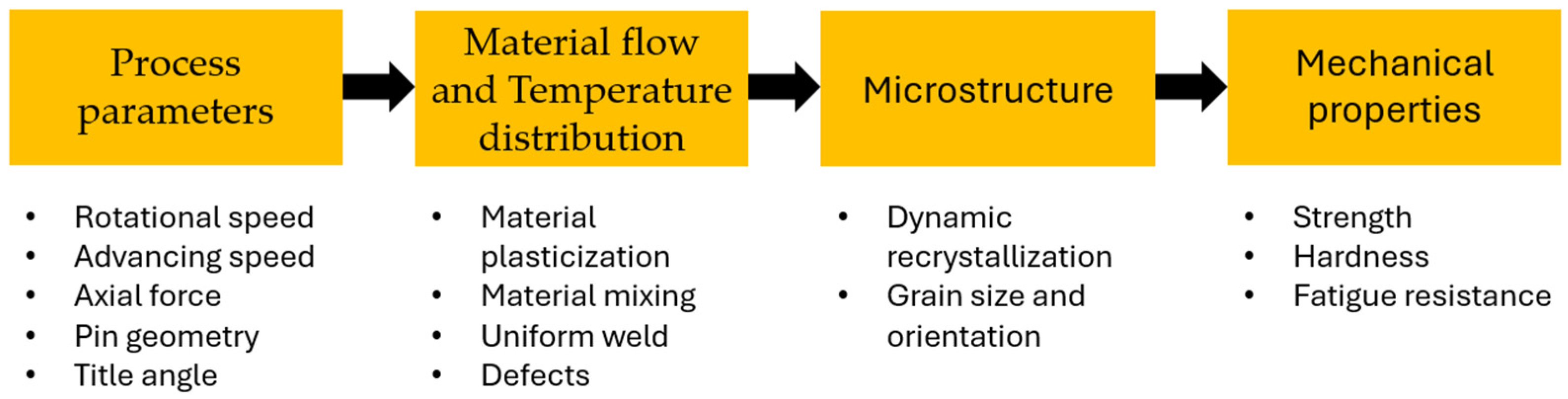
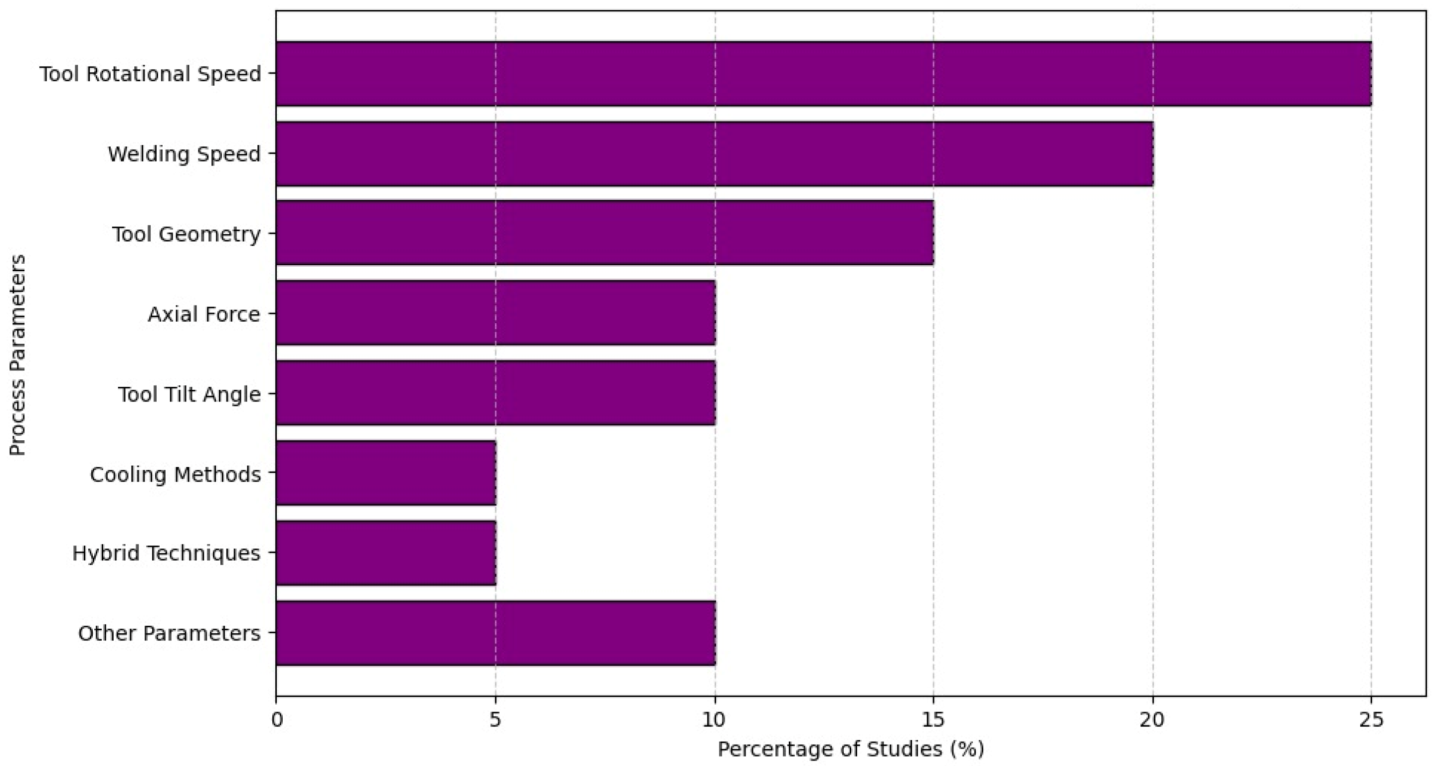
4. Friction Stir Welding Process Parameters

Friction Stir Welding relies on key process parameters that govern heat generation, material flow, and temperature distribution in the weld zone (see Figure 2). These factors influence dynamic recrystallization and microstructural evolution, resulting in refined grain structures and controlled phase transformations. These microstructural changes determine the mechanical properties of the joint, such as strength and hardness.
Rotational speed, welding speed, and axial load are the most essential parameters in the FSW process. These parameters significantly influence joint quality and mechanical performance. Assessing the impact of FSW parameters requires post-weld metallurgical analysis and evaluation of mechanical properties under varied conditions [19,20]. Variations in process parameters alter the weld metal characteristics, directly affecting joint performance. However, favorable outcomes are typically achieved only within a narrow range of parameter combinations. There are also interactions between some of these factors [21].
In FSW, the tool’s rotational speed plays a critical role in controlling material flow, heat input, and weld quality. Increasing the rotational speed raises the weld temperature, promotes thorough stirring, and enhances joint strength by producing a more uniform microstructure.
Asmare et al. [22] found that for AA6061-T6, increasing the tool speed from 900 to 1400 rpm (at a fixed travel rate) resulted in a significant increase in hardness in the stir zone and an increase in tensile strength from 217 MPa to 283 MPa (a joint efficiency of approximately 91%). In fact, joints made at 1200–1400 rpm were free of internal flaws, while joints made at lower speeds displayed discontinuities. This is because the higher rotation speed provided enough plasticization and heat to produce a weld free of defects.
Similarly, Sabry et al. [23] discovered that a high rotation speed of 2000 rpm with a welding speed of 10 mm/min produced a peak hardness of 114 HV and a UTS of 381 MPa in a dissimilar AA2024/A356-T6 weld. This was due to a high peak temperature of 504 °C and vigorous stirring. The two alloys mixed well under these high heat input conditions, but at the expense of increased residual stress of approximately 76 MPa and tool wear.
For instance, variations in tool rotational speed and welding speed notably affect weld strength and defect formation. Specifically, a study on AA2024-T3 and AA7075 alloys revealed that increasing the rotational speed from 1000 to 2000 rpm and adjusting the welding speed to between 10 and 15 mm/min significantly influenced the weld’s mechanical properties and defect occurrence. Optimal combinations of these parameters led to improved tensile strength and reduced defects like tunnel voids and hooks [20].
Interestingly, too much rotational speed can be harmful, Di Bella et al. [24] found that lower rotation speeds of 500 rpm vs. 900 rpm, at 100 mm/min welding speed actually produced better mechanical properties for dissimilar AA5083–AA6082 T-joints. While 900 rpm generated turbulent flow that resulted in wormhole defects and softening in the AA6082 region, 500 rpm welds displayed a uniform hardness profile and higher pull-out strength. This emphasizes that there is an ideal range: too fast a tool speed can overheat the material and create voids or grain coarsening that weaken the joint, while too slow a tool rotational speed can result in incomplete mixing or “kissing bond” flaws (unbonded faying surfaces). Excessive rotation speeds in heat-treatable alloys, such as AA2024/AA7075, can dissolve or coarsen strengthening precipitates, creating soft zones that localize strain and lower fatigue resistance and static strength.
In contrast, a moderate rotation speed balances heat input and material mixing, Beygi et al. [25] optimized an AA2024–7075 butt weld at 1110 rpm (with a cylindrical pin) to achieve 395 MPa UTS, observing that lower speeds led to obvious defects (e.g., root voids) while higher speeds offered no further benefit. In summary, rotational speed must be tuned to the alloy combination and thickness. It critically affects weld integrity, and both insufficient and excessive RPM were shown to introduce defects or softening that compromise joint strength and fatigue life. Researchers consistently identify tool rotation speed as one of the most influential parameters, often the single strongest factor governing weld tensile strength and hardness in aluminum FSW.
The welding speed or travel speed, which is the linear speed at which the Friction Stir Welding tool moves along the joint line during the welding process, has an inverse relationship to heat input, strongly impacting weld formation and properties alongside rotation rate. A slower travel speed increases the dwell time of the tool in a given area, thereby raising the heat input and plastic deformation, whereas a faster speed lowers the heat and can lead to “colder” weld conditions. In practice, reducing the traverse speed can boost weld strength up to a point by ensuring adequate stirring.
Reducing the travel speed from 47.5 mm/min to 37.5 mm/min at high rotation increased the joint tensile strength by approximately 30% (from 217 MPa to 283 MPa) and resulted in a harder nugget in the same AA6061 study. Internal voids were removed and nearly full-strength welds were made possible by the slower traverse’s high heat input. The lowest tested speed (10 mm/min) produced the best performance dissimilar weld (AA2024/A356), while a slightly faster speed of 15 mm/min led to a 10% decrease in UTS and hardness, according to Sabry et al. [23].
On the other hand, excessive material flow or overheating may result from very slow speeds. Consistent with Asmare et al. [22], although some welds produced at the lowest speeds still had high tensile strength, they displayed flash extrusion defects on the advancing side (excess metal expelled from the joint) as a result of the extended heating. This suggests a trade-off: higher traverse speeds minimize heat input but run the risk of internal defects, while very low traverse speeds maximize strength but may cause surface flash or expand the heat-affected zone.
Where thorough welds are produced, there is generally an ideal intermediate welding speed: a speed below that can result in overheating or grain growth that softens the weld metal, while a speed above that will leave voids or unbonded regions (severely degrading fatigue performance). On a 7xxx alloy, Beygi et al. [25] showed the following balance: raising the travel speed from 50 to 100 mm/min decreased weld-zone grain coarsening, but once critical heat input thresholds were not reached, the tensile strength decreased.
In practice, a lot of research uses moderate traverse rates (e.g., 20–100 mm/min for 5–10 mm plates) in conjunction with an appropriate tool rotational speed to attain peak weld strength [26]. The ideal speed is contingent upon the thickness of the plate and the thermal characteristics of the alloy; thick sections or alloys with low thermal conductivity (such as copper-bearing AA2024) typically need slower speeds to prevent defects, while thin sheets or highly thermally conductive alloys can withstand faster speeds. To control the net heat input, traverse speed and rotation speed must be optimized together. A weld speed that is too fast results in fusion defects, while a speed that is too slow causes diminishing returns and possible flash or softening of the weld metal [27].
Moreover, material flow, weld microstructure, and defect formation are all significantly impacted by the design of the FSW tool, especially the shoulder features and pin (probe) profile. Different pin geometries result in different stirring patterns. For example, simple cylindrical pins may cause less turbulence, while threaded or fluted pins enhance mixing and help in breaking up oxide layers. Therefore, stronger, more uniform welds are frequently the result of optimized pin shapes. Research indicates that a tapered and threaded pin profile enhances material mixing and reduces defect formation compared to cylindrical or square profiles, leading to superior joint strength and integrity [28].
The highest joint strength and hardness for AA6061 was achieved with this shape of pin, particularly at high rotation speeds. The triflute (three-flatted) pin maxed out at 217 MPa and 54 HR under the same conditions, but the taper-thread pin at 1400 rpm achieved 283 MPa UTS and 71.6 HR hardness in the nugget. The superior stirring action of the threaded pin produced a more uniform and fine-grained stir zone, which resulted in a weld efficiency of approximately 91% [22].
In their evaluation of three pin profiles—cylindrical, conical, and pyramidal—Beygi et al. [25] found that, under ideal conditions, the cylindrical pin produced the highest tensile strength experimentally of 395 MPa. While the sharper conical/pyramidal tools tended to leave a partial “kissing bond” defect at the weld root under suboptimal conditions, the cylindrical tool, which had the largest pin volume (≈10 mm3), allowed for better material mixing of the two alloys. The use of less-than-ideal pin shapes or insufficient rotation resulted in those kissing bonds (weak, unbonded interfaces) and banded structures, underscoring the significance of pin geometry in preventing internal defects.
Similarly, Elangovan et al. [29] demonstrated that tool pin geometry notably affects material flow and the formation of defects like hooks and tunnel voids in AA2219, which share similar characteristics with 6xxx series alloys. To quantify weld soundness, a Weld Nugget Quality Index (WNQI) has been proposed in various studies to assess nugget size and internal defect presence.
Another important factor is the shoulder’s design, which includes its diameter, features, and concentricity. More frictional heating and forging are provided by a larger shoulder; however, excessive flash or unstable flow may result if the shoulder is too large in relation to the pin size. Di Bella et al. [13] observed that for dissimilar AA5083/6082 welds, the shoulder-to-pin diameter ratio needed to be adjusted; they found that a 15 mm shoulder (with a 6 mm pin length and 2.5 ratio) at 1000 rpm produced the best results. Scrolls and shoulder knurling are examples of tool features that help trap material and stop expulsion. Essa et al. [30] recently created an eccentric shoulder tool (a cam-like shoulder that is slightly offset) for FSW of AA6082 that greatly enhanced material flow without the need for tool tilting. The eccentric-shoulder tool at 0° tilt yielded the highest tensile strength of 216.5 MPa (89.7% joint efficiency) and a weld nugget grain size of 1.63 µm under the same conditions (600 rpm, 250 mm/min). This is significantly finer than the 2.79 µm obtained with a conventional concentric shoulder. The eccentric shoulder’s enhancement of plastic flow and forging pressure in the weld zone was evidently responsible for the nugget’s improved hardness recovery and grain refinement. In contrast, even though the standard tool required a 3° tilt to produce sound welds, it produced slightly coarser grains and lower strength in this study.
These results demonstrate how adjustments to tool geometry (shoulder design, pin shape, and thread profiles) can expand the processing window and enhance weld quality. Proper pin geometry prevents internal voids and promotes fine equiaxed recrystallized grains, while shoulder design regulates surface finish and flow consistency. Tools with optimized features such as threaded pins and appropriately sized shoulders produce stronger, defect-free welds by enhancing material mixing and joint consolidation. In the automotive sector, achieving flawless welds with high fatigue resistance—particularly in 7xxx alloys—requires precisely engineered tools, such as threaded pins. Empirical research on a variety of alloys (AA6082, AA7075, etc.) has shown that tool geometry can be just as important as process parameters. Therefore, the key to enhancing weld performance is selecting optimized or novel tool geometries.
The downward force or pressure that the tool applies (known as axial force) is another critical parameter influencing weld quality. This parameter controls how well the material is forged together and how deeply the tool shoulder and pin penetrate. Adequate axial force is essential for complete weld consolidation; insufficient force causes incomplete joints, while excessive force may lead to surface flash or tool wear [31]. Studies have shown that applying optimal axial force ensures sufficient material consolidation and minimizes internal flaws. Improper axial force, whether too high or too low, can cause voids or incomplete fusion, compromising the joint’s mechanical integrity [32,33].
Axial load’s effects are widely known. Parasuraman et al. [34] conducted a study on thick-section AA7075-T651 (10 mm plate) where they demonstrated that achieving 412 MPa tensile strength and 9% elongation required a high axial force of 12 kN, with process parameters set at 750 rpm and 30 mm/min. Efficient stirring and full-depth consolidation enabled the weld to retain 88% of the base metal’s strength and 80% of its fracture toughness. High forge force improved the joint’s load-bearing capacity and crack resistance, while also minimizing internal defects and promoting fine-grained microstructure via intense plastic deformation [35].
On the other hand, a tunnel defect or nominally bonded seam would remain at the bottom of the weld if there was not enough axial force to penetrate the entire thickness. When insufficient downforces were applied, these tunnel defects were seen, showing up as continuous cavities along the weld root. Because they act as sites for crack initiation under cyclic loads, these internal tunnels or kissing bond defects significantly weaken the weld and are particularly harmful to fatigue performance. As is well known from welding high-strength alloys like AA2024 and AA7075, fatigue-critical applications require a high enough forge force to prevent “lazy S” kissing bonds at the root.
However, too much axial force can cause other problems. An excessive amount of force can cause plasticized material to be expelled outward, resulting in flash defects (expelled metal ridges) along the weld crown or root. This is because a higher downforce raises the hydrostatic pressure in the weld zone. Severe flash can reduce static strength by thinning the weld cross-section and requiring post-weld machining. Furthermore, an excessively high axial force increases the tool’s stress, which can increase spindle torque and increase the chance of tool fracture, particularly in thick sections or hard alloys.
In order to prevent internal voids and ensure metallurgical bonding, the axial force must be optimized. It should be high enough to maintain intimate contact and mixing, but not so high as to result in significant flash or tool overload. Forces of about 5 to 15 kN are typically applied to aluminum alloys that are 5 to 10 mm thick; research has identified sweet spots for various alloy combinations within this range. For instance, Raman et al. [36] maximized tensile strength without defects by optimizing the FSW of 1.6 mm AA2024-T3 and determining an ideal forge force of about 10 kN (at moderate speeds).
Ghiasvand et al. [37] demonstrated that in order to achieve approximately 90% joint efficiency in thicker dissimilar welds (such as AA6061 to AA7075), a minimum plunge depth of 0.1 mm (enough to generate pressure) and roughly 6 kN force were required. In general, uniform weld properties can be achieved by maintaining a constant axial force during the welding process; force-controlled FSW machines are frequently used in the automotive industry to dynamically adjust downforce and prevent defects. Weld soundness and forge quality are largely impacted by axial force. While an adequate force guarantees complete penetration and consolidation (which increases weld strength and toughness), an inadequate force results in internal flaws and weak joints, and an excessive force can cause flash and possible tool or workpiece damage. High-strength alloys with limited processing windows, such as AA7075 and AA2024, benefit greatly from optimizing this parameter because void-free welds are made possible by the right axial pressure, which has been shown to increase joint fatigue life and load capacity [38].
Another important factor that affects the quality of the weld is the tool tilt angle, or the angle at which the tool is inclined relative to the workpiece. In FSW of aluminum, a small forward tilt (usually ~1–3°) is frequently employed to ensure that the tool shoulder presses the plasticized metal into the joint and to direct the material flow downward [39]. The tilted tool’s forging action helps “seal” the weld behind the pin and prevent flaws like unfilled grooves or surface voids. According to research, a proper tilt angle significantly enhances weld formation by encouraging material to forge downward into the joint line and minimizing the formation of defects in the stir zone.
In FSW of aluminum AA2024, Rajendran et al. [40] found that employing a tilt between 1 and 3 degrees produced welds that were free of defects and had exceptional strength and hardness, while a tilt of 0 degrees under comparable circumstances tended to produce surface flaws or sporadic bonding failure. According to these results, a small tilt is advantageous. For aluminum alloys, tilting the tool about 2 degrees is usually ideal because it improves forging pressure and helps fill cavities with plasticized material. Without tilt, there is a greater chance of voids at the crown or lack-of-fill flaws because the tool might only stir the material in place rather than sufficiently pushing it into the joint. However, excessive tilt can result in a “thinner” weld nugget cross-section or surface flash by reducing the shoulder’s contact area and creating an excessive buildup of material in front of the tool. In summary, the tool tilt angle affects the forging action and material flow beneath the tool shoulder.
An optimal tilt angle, typically around 2.7 degrees, has been found to enhance joint strength and reduce surface defects in AA6082/AA5083 welds [39]. Despite its geometric simplicity, this parameter is essential for ensuring that the stirred material is properly consolidated and that the weld achieves properties similar to those of the base metal, including good fatigue performance, because tilt improves forging and helps remove defect sites where cracks could start. Additionally, Di Bella et al. [24] established a clear correlation between optimized process conditions and enhanced weld quality through both FEM simulations and experimental validation. These findings provide a strong basis for selecting and adjusting process parameters to achieve consistent, high-quality joints in real-world automotive applications [41,42].
The FSW process is characterized by two primary forces that act, such as axial force and rotational force. These forces act as the main strength parameters that help to join the material. Measurement of these forces can help to study the material flow and its joint performance during FSW [24]. This approach is used to validate or discuss the weld shape of FSW. Important observations and optimal parameters are expected in finding or developing an innovative method of FSW with the variation of these process parameters. In conclusion, the rotational speed, welding speed, and axial force (downward force) in FSW are the most important operational parameters to optimize. These parameters are to be set to determine product quality based on the type of metal and the thickness of the welding [43].
The process parameters will strongly affect joint performance due to the gradual variation of the weld nugget zone, the heat-affected zone, the thermo-mechanically affected zone, and the molten zone created by setting the FSW parameters. The optimization process for these FSW parameters needs to be conducted for a specific thickness of the plates and expected product performance.

5. Discussion of Effects of Friction Stir Welding on Aluminum Alloys

5.1. Introduction to FSW and the Role of DRX

Initially introduced as a solid-state joining technique, Friction Stir Welding (FSW) has rapidly evolved into a commercially viable process, particularly well-suited for the joining of aluminum alloys. Given the unique properties of aluminum, such as its high strength-to-weight ratio, excellent thermal conductivity, and good electrical performance [44,45], a detailed understanding of FSW is essential. To this end, it is critical to investigate the process in terms of microstructural, metallurgical, and mechanical transformations, which in turn supports the design of optimized alloys and configurations tailored to specific engineering applications. This paper provides an overview of aluminum alloys welded using FSW, focusing on various studies that analyze microstructural evolution, metallographic features, plastic deformation behavior, and mechanical performance [46,47].
One of the most extensively studied features of FSW is the microstructure within weld nuggets. This zone typically contains fine, equiaxed grains formed through dynamic recrystallization, as well as sub-structured grains originating from the breakdown of the initial coarse grains present in the cast or rolled base material. In regions bordering the nugget, particularly near the nugget’s thermo-mechanically affected zone (TMAZ) interface, partially recrystallized grains are often observed, preserving aspects of the original microstructure. This grain refinement is predominantly attributed to intense dislocation activity and dissociation within the initial grains. However, the resulting fragmented grain orientations and equiaxed morphology can alter the material’s load transfer capacity, occasionally leading to shear banding within the nugget and substructure regions [48].

5.1.1. Dynamic Recrystallization (DRX) Mechanisms

A central mechanism underpinning this transformation is dynamic recrystallization (DRX), which plays a pivotal role in refining grain structure and enhancing mechanical properties [49,50].
In FSW, DRX predominantly occurs via continuous dynamic recrystallization (CDRX), characterized by the following:
  • Accumulation of dislocations due to severe plastic deformation, generating dislocation tangles and sub-cell structures that increase stored deformation energy [51].
  • Rearrangement of dislocation structures into low-angle grain boundaries (LAGBs), which progressively transform into high-angle grain boundaries (HAGBs).
  • Progressive rotation and growth of subgrains, culminating in the formation of new, recrystallized grains.
Although the fundamental mechanisms of DRX are well understood, its efficiency and characteristics are strongly influenced by thermomechanical conditions, particularly temperature and strain rate during welding. These parameters govern the onset, progression, and completeness of DRX and are crucial for tailoring the microstructure and performance of FSW joints [52].
Recent studies have expanded on established DRX principles, showing that temperature and strain rate critically influence the kinetics and extent of recrystallization. DRX kinetics are primarily driven by the interaction of deformation temperature and strain rate, which control grain nucleation and growth within the weld zone [53].

5.1.2. Influence of Temperature on DRX

Elevated temperatures during FSW enhance the mobility of dislocations and grain boundaries, thereby promoting the formation of new, equiaxed grains through DRX optimal thermal input, which facilitates dynamic recovery and recrystallization, resulting in refined microstructures and enhanced mechanical performance. Excessive heat can cause grain coarsening, while insufficient temperatures may inhibit recrystallization, leading to residual stress and uneven grain structures.
For example, in a study on AA7075-T651 aluminum alloy [35], deformation at temperatures between 300 °C and 400 °C led to significant grain refinement and improved mechanical behavior. These findings emphasize the role of adiabatic heating in promoting DRX and triggering the shear band and crack phenomena associated with plastic instability at elevated temperatures.

5.1.3. Influence of Strain Rate on DRX

Strain rate, alongside temperature, is another pivotal factor influencing DRX in FSW. Lower strain rates allow more time for dynamic recovery and continuous dynamic recrystallization (CDRX), resulting in uniform, fine-grained microstructures. In contrast, higher strain rates increase dislocation density, favoring discontinuous dynamic recrystallization (DDRX), characterized by the nucleation of new grains at sites of elevated stress [54].
A recent study on the hot deformation behavior of recycled Al–Zn–Mg–Cu alloys identified optimal hot-working parameters in the temperature range of 300 °C to 360 °C and strain rates of 0.01–0.05 s−1. The authors highlighted the necessity of carefully controlling both parameters to promote effective DRX and avoid the formation of defects.

5.1.4. Combined Thermomechanical Effects and Microstructural Zones

The combined effect of temperature and strain rate determines the DRX mechanism and the resulting microstructure. In the stir zone (SZ) of FSW joints, severe plastic deformation and elevated temperatures lead to the formation of fine, equiaxed grains through CDRX. Adjacent regions, such as the thermo-mechanically affected zone (TMAZ), may experience partial recrystallization, resulting in heterogeneous grain structures [55].
An example of this is observed in the FSW of AA6082-T6 aluminum alloy [56], where the microstructure of the weld nugget zone is significantly influenced by welding parameters. Higher rotation speeds and appropriate tool designs promote extensive dynamic recrystallization, leading to finer grain sizes and improved mechanical properties.
The grain refinement achieved through dynamic recrystallization not only influences microstructure but also plays a crucial role in determining the mechanical performance of FSW joints. To further explore these relationships, the next section delves into the microstructural evolution processes that occur throughout the different zones of a weld.

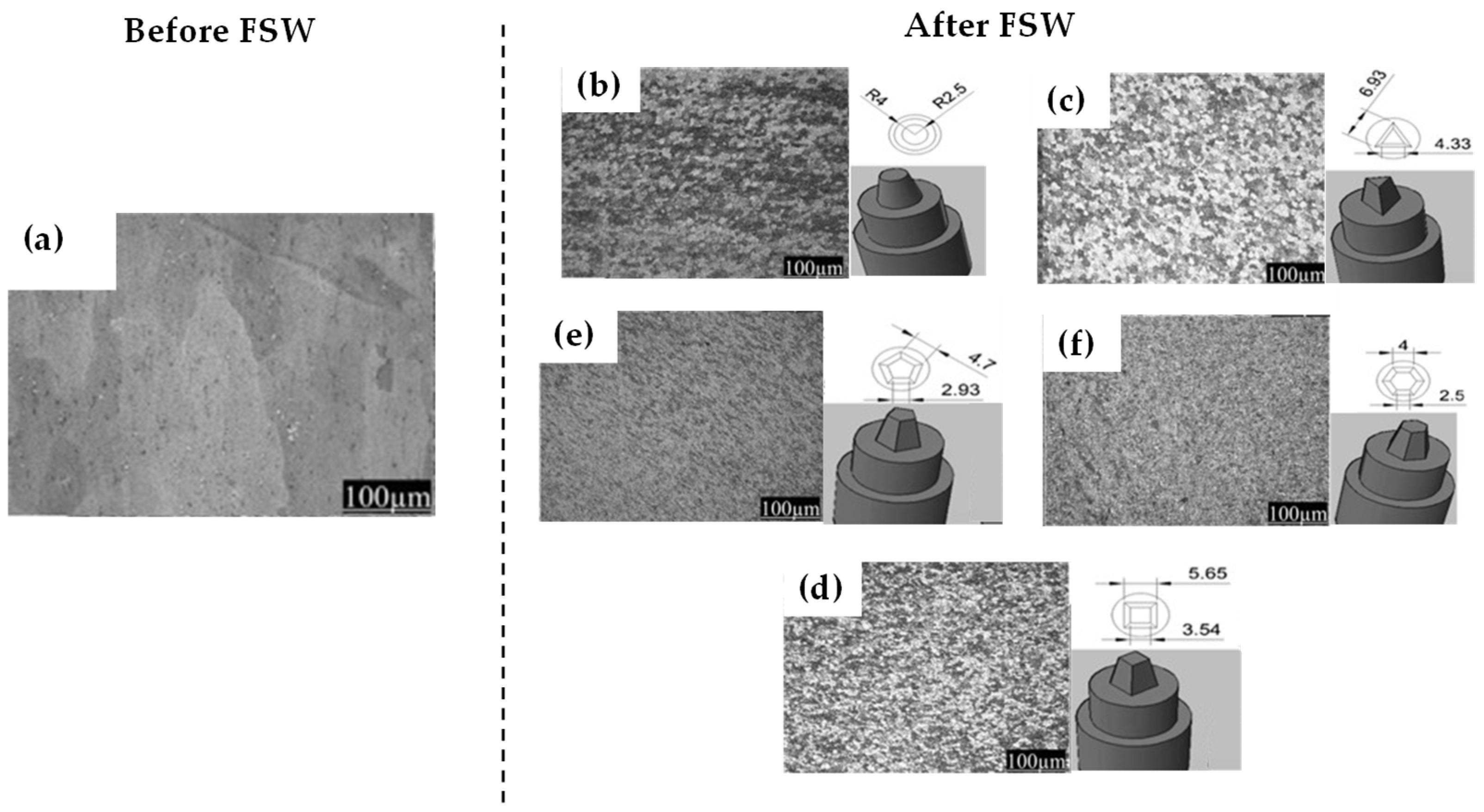
5.2. Microstructure Evolution

Understanding the microstructural evolution that occurs during FSW of aluminum alloys is essential, as the resulting weld characteristics and performance are largely determined by these transformations. Key indicators such as grain size, phase distribution, and orientation vary significantly across the weld zones and are influenced by welding parameters and alloy composition. The grain-refined matrix of the Al alloy indicates superior behavior of FSW with the AA6xxx alloy group or the 7xxx series [16,57]. To stop the initiation and growth of a brittle phase in the weld nugget zone, refining the microstructure results in a significant reduction in crack propagation. Constituents’ performance factors, such as the properties or hardness inside the stir zone or thermo-mechanically affected zones, are also important. Dynamic recrystallization is an imminent strategy that helps in the modification of the microstructure. Observations of dynamic recrystallization are achieved with the help of methodologies developed in the field of microstructural investigations [58]. Several investigations have elaborated on changes occurring in the microstructure in terms of the parameters used in the welding of Al alloys, such as tool rotation speed and welding peak parameters [31].
Investigators have found that an ultrasonic field is very effective in improving grain refinement and the densification of the weld region, which is the direct consequence of reduced grain size while having no detrimental effect near the surface or thermo-mechanically affected zone. The interaction in the vicinity of the welded zone between mechanical stirring and thermal effects has been emphasized [59,60].
Maintaining precise thermal control throughout the stir zone is essential, as it directly governs the formation of equiaxed grains, the size and morphology of intermetallic particles, and overall weld quality. Material flow and mixing, particularly along pin threads, play a critical role in promoting dynamic recrystallization, which in turn enhances mechanical and corrosion resistance. The peak temperature during FSW significantly influences the grain refinement and structural morphology of a joint. Observations show that material from the upper layers is transported downward by the pin threads, incorporating intercritically transformed zones. During tool retraction, material flow patterns reveal that approximately 80%, 40%, and portions of the pin-threaded material remain embedded in the weld. Two distinct stages of dynamic recrystallization especially evident at the midplane and near the tool exit have been linked to thread position and local thermomechanical conditions [61].
These microstructural changes, driven by thermal input, material flow, and tool geometry, ultimately govern the mechanical behavior of welded joints. The following section examines the impact of FSW on key mechanical properties such as strength, ductility, hardness, and fatigue resistance [62]. This can lead to different microstructures in the nugget zone, which can impact the strength and corrosion of the weld, as can be seen in Figure 3.
At higher tool rotation speeds, the fraction of recrystallization is reduced, but it is larger in the case of the threaded part of the pin. Early recrystallization is observed near the pin threads, where intense plastic deformation between the pin and base metal promotes greater grain refinement. Practically, this has also been checked by making a hole in the rotating tool it was found that this is the location where dynamic recrystallization starts [63].

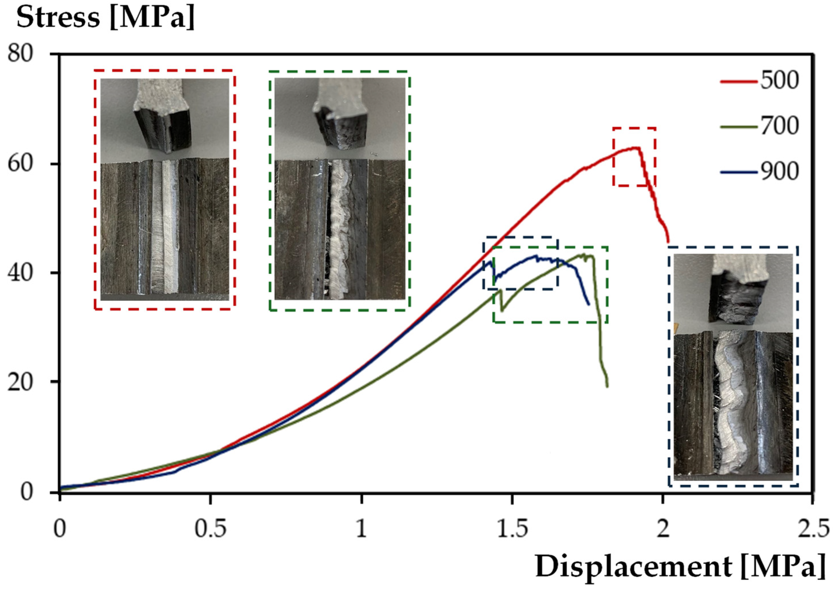
5.3. Mechanical Properties

Compared to traditional fusion welding methods, FSW significantly enhances the mechanical properties of aluminum alloys. Improvements in tensile strength, ductility, and fatigue life are largely attributed to the refined, homogeneous microstructure created through solid-state plastic deformation and recrystallization. Due to these simultaneous positive influences, the obtained tensile strength, ductility, and fatigue life are enhanced by 80%, 116%, and 90%, respectively [64]. The superior mechanical behavior of FSW aluminum alloys is attributed to their homogeneous, fine-grained microstructure, which offers greater strength and ductility than the coarse grains typical of fusion welds.
Microhardness analysis shows that the stir zone exhibits significantly higher hardness than the thermo-mechanically affected zone, due to grain refinement, densification, and precipitate redistribution induced by severe plastic deformation [63]. Studies using SFRP and flow stress models indicate that higher tool traverse speeds and strain rates increase heat input, enhancing mechanical performance through improved work hardening, ductility, and phase reprecipitation [65,66].
Additionally, following their investigation on the range of stress intensity thresholds, it was argued that resistance to crack growth in the stir zone is higher compared to the parent base metal [67]. These reasons are attributed to a series of microstructural modifications leading to an increase in the resistance to crack initiation and propagation. Despite all these advantages, it is important to mention that a few drawbacks corresponding to the mechanical behavior of FSW aluminum alloys may be observed. In FSW, a strong interaction between transverse residual stress and tensile properties has been reported, suggesting a trade-off between favorable residual stress fields and optimal mechanical performance [68]. Further studies confirm that, for some alloys, balancing tensile strength and corrosion resistance is necessary to ensure suitability for a wide range of applications [20,69].
In [24], the study examines how varying the rotational speed during FSW affects the mechanical properties of T-joints, specifically at speeds of 500, 700, and 900 rpm. From Figure 4, the curve joints made at 500 rpm show higher stress values compared to those made at 700 or 900 rpm. A lower speed resulted in fewer defects. These defects acted as stress concentrators at higher speeds, reducing the strength of the resulting welded joint.
While optimized FSW conditions can significantly improve mechanical properties, another critical factor influencing joint performance is the presence of residual stresses. The next section discusses how these internal stresses are generated, measured, and how they influence the structural integrity of FSW joints [70,71].

5.4. Residual Stresses and Distortions

FSW employs unique thermal and mechanical boundary conditions that permit this solid-state welding process to create a homogeneous weld joint but can also cause internal stresses within the joint known as residual stresses. Such internal stresses can modify the mechanical behavior and the start of plastic yielding. Therefore, they may accelerate the fatigue failure process. Consequently, the residual stress state of the welded structure is critical for its mechanical integrity and life. However, how residual stresses affect welds can change based on the processing conditions. This is due to the current knowledge that states that the same residual stress fields in welds can have no or limited impact under one set of welding conditions and a catastrophic effect under other welding conditions. Investigating how residual stresses contribute to the performance of the overall weld is a focus for most analysts [72].
Residual stresses can be measured using several techniques [71], like the incremental hole-drilling method, X-ray diffraction, neutron diffraction, and the contour method. The common industrial method for residual stress determination is the X-ray diffraction method, where lattice plane deflection is used to measure in situ macro stress in the top surface of the material. The contour method is a destructive technique based on measuring thickness variations along the marked line of the specimen surface to determine longitudinal and transverse residual stress around the marked line. The contours are created by grinding both surfaces of a uniform-thickness specimen and marking a line to initiate the removal of material. The magnitude of the contour displacement after the removal of the material from one side of the core is used to obtain the residual stress [73].
Based on a lever arm and the compliance of the sample, the resulting residual stress can be calculated. The choice of integration path is pertinent and can be conceived as open paths in the shape of either concave, convex, or mixed curves or by selecting closed paths. In general, techniques like the contour method or high-energy radiation X-rays can measure the distribution of residual stresses with high accuracy. To date, none of these residual stress measurement techniques have been extensively applied to dissimilar joints produced by Friction Stir Welding [68].
Table 1 contains a comprehensive summary of the results of various studies on the effects of Friction Stir Welding (FSW) parameters on welding performance. It categorizes the most important process parameters, such as rotation speed, welding speed, axial force, tool geometry, tilt angle, and others and lists the specific conclusions of the various researchers. Each entry in the table describes in detail how a particular parameter or combination of parameters affects results such as heat input, material flow, microstructure, and mechanical properties.
The distribution of the discussed research results on the parameters of the FSW process is shown in Figure 5. The bar chart shows that mold speed is the most studied parameter in FSW research, reflecting its key role in controlling heat generation and material flow. Welding speed is the second most studied parameter, while tool geometry and axial force also attract considerable attention. In contrast, comparatively little attention is paid to parameters such as tilt angle, cooling methods, and hybrid techniques, suggesting that researchers tend to prioritize the fundamental variables (e.g., rotation and welding speeds) that have the most direct impact on weld quality and microstructure.

6. Advantages of Friction Stir Welding in Aluminum Alloys

One of the greatest advantages of the FSW process is the capacity to produce high-strength joints with minimal defects compared to conventional joining processes. The lower heat input achieved in FSW results in an improved distribution of mechanical properties through the weld region, reflecting the mechanical properties of the base material. Moreover, FSW generates less residual stress, which contributes to enhanced fatigue performance. The reduced thermal exposure of the material also helps to maintain high properties in the heat-affected zone. In conventional fusion welding, temper softening in the heat-affected zone often limits the performance of the welded component. Friction Stir Welded joints have demonstrated good fatigue performance compared to counterpart fusion welded samples for a variety of base material combinations and joint configurations [95].
In addition, the FSW process is particularly attractive for materials with a high strength-to-weight ratio, such as aluminum, since it can be used to weld lightweight materials with a minimum of heat input, thus preserving their mechanical properties. For some aluminum alloys, Friction Stir Welded joints even display higher strength than the base material due to the ultrafine grain size created in the stir zone [96]. Furthermore, since FSW is conducted without any filler material, it does not introduce undesirable corrosive effects that could arise with the application of dissimilar materials. The joints possess good corrosion resistance, which can be further enhanced if an outer seal is applied to isolate the cap material and prevent oxygen from reacting with the adjacent material [97].

6.1. Improved Mechanical Properties

Surprisingly, the fatigue behavior in several types of aluminum FSW joints is superior to or at least comparable to their base material. For aluminum FSW joints, fatigue strength is enhanced owing to the geometric factors related to the FSW tool and pin. The FSW welds in aluminum have better tensile properties than GTA welds owing to the absence of solidification porosity from the stirred zone. The tensile properties are enhanced when FSW is performed in a counter-rotating manner compared to single-pass FSW owing to a finer recrystallized grain structure. Similarly, a superior tensile strength of 85% compared with the base material in 7475-T7351 Al-joining was produced [98]. The microstructural refinement conspicuously influences various mechanical properties of the joint. In aluminum–lithium alloys, precipitation hardening enhances tensile strength and significantly improves mechanical performance during FSW.
Aluminum alloys show an increase in yield strength with increasing hardness measured using various micro-indentation techniques. The tensile strength and hardness of FSW Al 2024 joints exceed those of the base material, confirming reported mechanical improvements. FSW has been shown to improve key mechanical properties, such as tensile strength, wear resistance, and hardness in aluminum alloys [98,99].
Globally, FSW enhances toughness, including fatigue resistance, impact strength, and fracture toughness, in aluminum alloys. The strength and fatigue resistance improvements achieved through FSW offer significant durability advantages for aluminum alloy components in real-world applications. The benefits of higher strength and lighter weight are especially critical in automotive and aerospace applications. Despite extensive research on optimizing mechanical behavior, service conditions such as long-term environmental exposure remain underexplored in FSW studies. This is one area to be seriously considered in the future. Optimizing FSW mechanical performance requires precise control of welding parameters and careful stir zone design. At this stage, we are trying to design methods and further studies to obtain higher performance than fused welds or the base material [100,101].

6.2. Enhanced Corrosion Resistance

In conventional welding, the use of filler materials can introduce new corrosion vulnerabilities. Welded regions are particularly susceptible to environmental degradation. In contrast, Friction Stir Welding (FSW), being a solid-state process, offers both mechanical and corrosion-related advantages. Localized softening due to frictional heat and pressure facilitates grain refinement and phase transformations, resulting in over 25% plastic deformation under high thermal input. This enhances both bending strength and corrosion resistance, often matching or exceeding that of the parent material. FSW joints exhibit shallower pitting depths, reduced crevice corrosion risks, and improved sealing integrity. For instance, in aluminum 5000 and 7000 series alloys used in marine environments, FSW has demonstrated high corrosion resistance with no significant service failures. It has also been shown to reduce the likelihood of pitting re-initiation after defect removal [102].
Moreover, Friction Stir Welded components such as AA5086-H19 and AA6082-T6, show lower susceptibility to stress corrosion cracking. Alloys like AA5454-H3 and AA5254 exhibit intermediate resistance, with corrosion lines appearing after 4 to 12.5 days, compared to 3.5 days in the parent metal. Post-weld treatments have further improved resistance to both uniform and localized corrosion. The fusion zone has demonstrated superior resistance to uniform corrosion when compared with both the base metal and the heat-affected zone. Improved behavior in the heat-affected zone under marine conditions is attributed to slag deposition at the root surface [62].

6.3. Environmental Benefits

In the Friction Stir Welding (FSW) system, energy is preferable to flow at the intended location and improves welding efficiency. Generally, FSW consumes almost less than 5% of the energy of conventional welding processes. This demonstrates the efficient use of energy during FSW. FSW decreases the requirements for chemical fillers and fluxes. It also reduces harmful metal fumes and harmful ultraviolet light to protect the environment. Aluminum scraps occur in good joints and can be recycled. Most FSWs contribute to environmental sustainability, including the rehabilitation of scrapped aluminum, because new technological structures are designed to comply with environmental protection regulations and be returned to the production chain. Weight in the automotive and aerospace sectors is considered one of the most important features that contribute to improved energy and environmental efficiency [103]. The fuel potential of less burnt fuel in lighter planes and vehicles is significant. Also, the use of services that do not require increased energy transmission helps to protect the environment. Friction stir processing directly produces 50% to 60% less cost compared to single-stage manufactured materials, and the process will be cheaper in terms of waste materials. The inferior quality welding produced by the increase in wastage rate can often be decreased so that good-quality welding is produced with other combinations of process parameters. Additionally, this procedure using sensors included in the machine tool may carry out environmental control and bring sustainable manufacturing closer to a “No Defect” process [104].
Friction Stir Welding (FSW) is growing as a credible option for the production of ecologically friendly materials, as well as for other types of welding practices. For next-generation industries like the automotive industry and aerospace, lighter and stronger materials are necessary. At the same time, the adoption of enhanced, innovative materials and technological advancement can help in developing operational efficacy and environmental effectiveness by addressing significant problems such as reduced vehicle weight and enhanced fuel efficiency. The potential benefits of FSW aluminum structures for fuel economy and environmental sustainability are identified. Such information can be better utilized for designing a variety of eco-friendly development and production systems. The updated scenario shows the future trend of environmental protection and may provide substantial information to be enforced by stakeholders, particularly research traditions and technical institutions, which can contribute to eco-friendly production research, accessibility of products, and recirculation and use efficiency [105].

7. Challenges and Limitations of Friction Stir Welding in Aluminum Alloys

Tool wear is considered to be the most significant challenge of Friction Stir Welding (FSW) because it can limit the performance of the weld/heat-affected zone (HAZ), joint performance (tensile strength and hardness), and, finally, worsen the weld quality. Different designs, cooling strategies, and/or different FSW configurations should be used to create a friction stir tool with improved wear resistance [106,107].
Process control and automation are difficult to achieve with FSW in aluminum alloys due to fluctuations in the working parameters, medium–high thermal gradients, and the ease with which the tool adheres to the welded materials’ start-up torque, particularly in high-strength aluminum alloys. Lack of full penetration can degrade the mechanical properties of the weld. Early detection of incomplete penetration is a very important task to ensure safe and efficient welding. Dissimilar aluminum alloys are more difficult to join than similar aluminum alloys due to inconsistent stirring, material flow, and different metallurgical reactions in the different zones of the weld. FSW made on dissimilar aluminum alloys can generate drop-shaped or vortex cavities and, in some cases, tunnelling cracks, showing very low resistance to traction because of little ductility. To overcome this challenge, the development of specific pin tool geometries must be carried out [108,109,110].
In [106], a novel stationary shoulder Friction Stir Welding tool (SSFSW) was developed to automatically remove plasticized material during the welding process. In this study, the SSFSW results in finer grains, as shown in Figure 6, especially in the NZ. The finer grain size and higher density of solidifying precipitates in the SSFSW compound contribute to its improved mechanical properties. The study suggests that lower heat input and effective material flow during SSFSW lead to these favorable microstructural properties.

7.1. Tool Wear and Maintenance

The FSW tool operates under high mechanical and thermal loads, which can accelerate tool degradation and failure. Friction Stir Welding was first thought of as a tool-damaging process. Since then, several approaches have been used to develop tool materials and identify the limits and benefits of FSW in terms of tool wear. In principle, it is important to understand the mechanisms of tool wear and accordingly plan feasible strategies for the maintenance of the tool. Additionally, new developments in tool materials may help prevent rapid tool wear while improving the performance of tools [74,110].
The wear mechanisms in the shoulder are adhesion, abrasion, and material transfer; moreover, in the thread, different areas can accompany wear as a result of the mechanical interaction of the tool with the different material zones and the combined thermomechanical loads. The studies show that W–Re tool material may be considered for welding 6082 aluminum as a result of the good wear resistance observed [71,111]. The increased cost of production due to tool replacement or maintenance for some applications is depicted. Tool wear-related costs represent an increasingly large part of Friction Stir Welding costs as the industry becomes more interested in resource efficiency [112].
Research on improved performance materials is an area of wide investigation aimed at improving the life of welding tools. Two common routes have been used to enhance the properties of FSW tools: ceramic or surface modifications and adding alloying elements. Past investigations have described the development and properties of ceramic materials, primarily based on aluminum [103]. Additionally, an Al2O3-based ceramic has been developed to improve the wear resistance of the FSW tool. A novel surface modification technique has been developed involving titanium nitride treatment on the FSW tool shoulder and pin, resulting in substantially improved wear resistance [108,109].

7.2. Process Control and Automation

A key challenge in Friction Stir Welding (FSW) is maintaining consistent weld quality under variable conditions and during continuous production. Industry feedback emphasizes the need for precise control of welding parameters to correct joint line imperfections introduced during blank production. Applied load, tool rotation speed, and traverse rate, along with tight welding tolerances in automated systems, significantly influence the FSW process. The quality of the performed FSW joints heavily depends on the fulfilment of desired process parameters. These can be critically analyzed in any particular FSW application [113,114].
Offline programming is currently required for tool path planning, as online programming through manual file translation into servo-control code is inefficient, slow, and time-consuming. Limited automation in conventional FSW reflects the challenges in achieving effective in-line process control. This has been enhanced by monitoring and adjusting process variables in real time. Real-time monitoring of weld characteristics allows for early detection of tool wear and automatic in situ compensation. The potential for reduction in manning levels within a production facility and subsequent manufacturing costs is expected to be a powerful driving force toward innovation in the field of automation. Robotic FSW systems offer cost-effective alternatives to manual welding, while also enabling broader industrial applications [115]. Individual research groups, organizations, or companies are utilizing their resources to find a better way of automating an FSW process. A newly developed robot allows the welding of larger components, with a top speed twice as high as the previous version, but it has reduced maneuverability. The new robot is to be launched in China [116]. Another research study has been conducted in the field for a better understanding of FSW machine selection for targeted automation application [81,117].
Ultimate Engineering and Automation are involved in the entire process of automation, encompassing tool development and software packages in the field of robotic automation. The FSW contraction process is monitored near the pin probe. The principle applied to the distance sensor attached to the forging tool is different from pin extension ratio in terms of stationary shoulder technology. Both of these sensors measure dynamically and continuously across predominantly used magnitudes of processing time during a weld [51,118]. Synchronization of data acquisition and data analysis tools measures and analyzes the sensors’ parallel description. At this point, the tools’ signal data are a snapshot of the stable, stationary phase of the FSW joint. The principal findings emerging from the ongoing study encompass real-time monitoring of weld quality via thermal signatures that use infrared cameras.

7.3. Joining Dissimilar Alloys

The joining of dissimilar partners is technique sensitive. The thermal–metallurgical response onset forms distinct behaviors for various materials. For example, in Al–Cu, Cu reacts with Al, while Fe undergoes a change in phase sequence during welding. This changes the materials’ bond quality. Thus, a single approach does not work for all material set combinations. To cope with this, strategies that can tailor the drilling for one material set or for one property or performance, such as mechanical properties or thermal behavior, would be important [60].
In Figure 7 from [119], the positioning of the base metals affects microstructure and mechanical properties of the macrostructures of joints welded at different speeds and positions of the 2024 aluminum alloy. When the 2024 Al alloy is on the advancing side, the structure appears to be more uniform. The investigations showed that defect-free joints typically break in the HAZ on the AA2024 side, in the region of the hardness minimum. The maximum tensile strength of the welded joints was 423 MPa and was achieved at a welding speed of 1.7 mm/s when the AA2024 alloy was on the advancing side.
In such cases, as well as using different tools or changing the welding speed, various innovative approaches that can modify the FSW zone are possible. The Changing Neck Shoulder, Tapered WWT technique, Ball Bearing Traveling Worm Gear, and other approaches that will come under tool designs are possible. A hybrid approach using FSW and other welding methods is also being investigated. However, the main limitation of these tool designs is the ability to create consistency in plastic working in the material composition and mechanical properties of the work material. Complete consistency in the innovative designs and success in weld performance would rely on the ability to produce a robust “one-step” joint. Research in such areas is in its infancy. It may be possible to extend the use of FSW in aluminum alloys if possible approaches can be developed [13].
In laser welding, a lot more research is also focused on how the thermal cycle affects weld performance, via testing in the thermal–metallurgical space. Some case studies focus on welding dissimilar Al with other materials, such as with 7050 Al–steel, with Ti-6Al-4V, and using FSW for dissimilar welds with A2-6013 Al. These possibly indicate some potential areas for future research. From such investigations, mechanical and thermal differences for a dissimilar weld between different materials can be identified, and appropriate remedies can also be obtained for potentially adapting to FSW applications [20].

8. Applications of Friction Stir Welding in Aluminum Alloys

One of the first fields where FSW was utilized was the aerospace domain. Over the years, FSW technology has undergone various improvements to meet the demanding requirements of the aerospace sector. New joining methods have also been developed to better cope with the harsh working conditions experienced in several segments of the production chain. Apart from the aerospace market, FSW technology has been introduced in other fields. In the automotive industry, the need for improving energy efficiency and passenger safety has led to the development of new lightweight vehicles featuring high structural integrity in their components. A significant number of those components are produced by Friction Stir Welding. The same goal prompted the introduction of FSW in the marine field, making possible the development of aluminum-intensive fast ferries on time- and cost-efficient grounds [6,120].
Figure 8 shows that the aerospace sector is the leader in the use of FSW with 40%, while the automotive sector accounts for 30%, mainly due to efforts to reduce vehicle weight and improve fuel efficiency. The marine sector accounts for 20%, where the corrosion resistance and joint integrity of FSW are particularly valuable. Other industries account for the remaining 10%.
In the current framework, FSW generates high-quality welds in terms of mechanical resistance and microstructure, characteristics suitable for use in several sectors. The versatility of the process allows for its use with different materials, not only aluminum, having developed various working tools capable of satisfying the working parameters required for joining different alloys. The technology’s ability to work in multiple areas has opened up new possibilities for its implementation and, together with its ability to treat complex geometries, offers various process advantages over existing alternatives. Several case studies are reported in this section which show the applicability of the technology to different industrial sectors with various applications. These are typical processes of the automotive industry, aerospace, and marine industry, the field of architecture, and also other emerging sectors. Through the reported results, it is possible to see the partial implementation achieved by FSW technology in the considered fields as a response to the industrial sector’s need to adapt to the requirements associated with each sector, which require product characteristics of high productivity, quality, lightness, and resistiveness. The examples reported show the results of the studies and analysis aimed at identifying the main technological trends and challenges [45,121,122].

8.1. Aerospace Industry

In comparison to other modes of transportation, aircraft transport [123] has rigid part design requirements, which include the need for very high strength-to-weight ratio materials, lightweight materials, heat-affected zone-free materials with good mechanical properties, and improved fatigue properties. Friction Stir Welding has proven to be an ideal welding method for meeting these requirements. A new method, the shaped tube cold expansion, has been invented that combines the resistance welding of other tubes onto the outer surface of vacuum tubes with the application of a mechanical, or ‘cold’ forming step while the tube is still in place. The tubes and vacuum tubes are then Friction Stir Welded [124].
To date, four FSW efforts within the aviation industry have materialized and information is in the public domain. The following studies illustrate how the welding process has been brought into these manufacturing efforts and the positive or negative tooling, engineering, and structural issues encountered in the manufacture of the aircraft wing structural assembly. A company approached the Friction Stir Welding development in combination with certain alloys and thinner and lighter materials simultaneously. However, government requirements demand the establishment of improved testing methods that will establish the predictability of FSW mechanical properties and aid in initial design. Conducting fatigue testing has demonstrated the effects of welding parameters on fatigue resistance. FSW offers increased fuel efficiency in part due to innovative aircraft design and in part through the use of lightweight aluminum and magnesium materials. Key links suggest that major aerospace engineering advancements should provide tangible evidence that weight savings can be accomplished with the same structural integrity. Tooling development companies are collaborating with aerospace companies in the further implementation of FSW technology [100,125].

8.2. Automotive Sector

The demands on the automotive industry are constantly increasing to make cars lighter, because they consume less and have less impact on the environment, without losing performance or passenger protection, and with lower operational costs. Stamping and drawing of aluminum sheets to make complex shapes that meet these demands, such as the chassis, is much more complicated than making an H-shaped beam, which is a great niche market where many companies use FSW for B2B. Vehicle body panels that have non-flat shapes not only demand greater stiffness but can also cross safety zones, such as fuel tanks and collision beams. These two cases have been confirmed. FSW was studied and employed by an automotive company [126].
Given that accidents are usually not intended to test the efficiency of a collision beam, much fewer structural strength details for FSW are required for most vehicles. In the field of passenger vehicle studies, one thing becomes clear. Case studies in selected vehicles confirm that companies either use FSW or are investigating the possibilities of using it, but only on a case-by-case basis in a niche market. Niche markets are usually at the options list level for vehicles. Note that none of the vehicle manufacturers mentioned commercial aircraft, buses, or trains, or the time required to phase out H-shaped connectors, and did not replace large-volume vehicles. With a few exceptions, which have their reasons, all the studied cases used FSW because it reduced the weight of the structure and improved integration. In terms of pounds, craft beef or skilled beef are difficult to find in company studies. Cross-industry company studies have the same problems [127].

8.3. Marine Applications

In marine engineering, especially when designing and constructing ships, aluminum alloys are mainly used. Based on their properties, these lightweight alloys play an important role in shipbuilding and, as a consequence, they have attracted researchers to use FSW because of its association with aluminum alloys. FSW is beneficial in marine construction and repair because it offers corrosion resistance and weight savings, as well as a lack of fumes and arc flash, and is sensitive to moisture. Ships and offshore structures have benefited significantly from a variety of FSW processes [128].
Projects attempting to use FSW for their benefit are as follows: tendering corrosion-resistant and high-performance FSW to the sides of composite-bodied ships; tendering repairs with the same strength and performance as the parent material; creating easily constructed, long-lasting, deep-welded joints; and repairing hull damage with FSW. In addition to this project, a report discussed FSW in a proposal for the repair of an aluminum ship. The hull of this ship was made by joining two laser-welded aluminum plates. The durability of the prismatic FSW technology was tested with much success. These ships and close-ups are used to create oil tanks using seal-welded FSW aluminum alloys [129,130].

9. Comparative Analysis with Conventional Welding Techniques

FSW was compared with traditional welding processes to understand the technique differences, performance analysis, and properties of the joined material. FSW provides lower heat input compared to other welding techniques, and thus thermal distortion is low in the welded part. With this technique, welding defects are minimal compared to other conventional techniques. Moreover, it is a technique that can be implemented using simple equipment alongside a high level of automated production. Three essential criteria are used for process comparison. They are technology capabilities, economic challenges for actual application, and research knowledge [131].
The challenges that are not encountered by conventional welding techniques are as follows: increased adhesion, unsuitable surface characteristics, and difficulty of tool removal. The technical and economic considerations are very important in deciding on FSW implementation. The primary challenge faced by FSW implementation is the cost of the tool. Additionally, the FSW process has been studied extensively, whereas the use of the FSW process for various applications has been comparatively less so. Also, its use in industrial mass production is limited at present. It is important to have an optimal solution when applying FSW for large-scale productions. Studies have compared total operational costs and joint qualities between FSW, friction stir spot welding, and other advanced welding and joining processes, such as gas tungsten arc welding and metal inert gas welding [132,133,134].

9.1. Discussion of Existing Studies on FSW

Because of its intriguing mechanical characteristics, aluminum alloys are frequently employed in a variety of industries. The weldability of these alloys is critical in the production of numerous product lines, as well as the assembly of structures such as strengthened panels [135,136].
To address the enormous demand for these structures, effective assembly procedures with the highest possible dependability and lowest possible cost are necessary. FSW, as previously said, stands out for its ability to achieve these goals. Several research efforts have been carried out on FSW. Researchers have been interested in developing welding equipment and processes for producing trustworthy welds, as well as characterizing the material’s behavior during welding.
Di Bella et al. [13,137] wrote a report on the welding process. The research looks at the most recent developments in numerical analysis of the FSW process, welded joint microstructures, and the characteristics of structures welded by this operation. The authors also addressed the significant numerical issues that arise when modeling the materials.
Colligan [138] investigated the dynamics of material flow during FSW of aluminum. The goal of this study was to document the movement of the material during FSW welding so that a conceptual model could be implemented to describe the resulting deformation process. Two novel methodologies for visualizing material flows during the FSW of 7075 and 6061 aluminum were presented. The results showed that the movement of the material in the welds is done either by simple extrusion or by chaotic mixing, depending on the area of the weld where the material originates.
Paik [45] investigated the mechanical characteristics of FSW welding of aluminum alloys 5083 and 5383. The idea was to develop a database of mechanical property testing on these alloys. FSW has been studied in the context of two similar alloys as well as distinct alloys. The outcomes of fusion welding were compared to those of FSW. It has been discovered that both methods of welding diminish the mechanical characteristics and tensile strength of the materials when compared to non-welded materials. However, whether for the assembly of materials between identical alloys or between different alloys, the tensile strength of alloys welded by FSW is larger than that of aluminum alloys welded by fusion.
Balasubramanian [88,139] examined five distinct aluminum alloys using various combinations of FSW welding parameters: AA1050, AA6061, AA2024, AA7039, and AA7075. The goal of this technique was to develop a link between the base metal and the welding parameters in order to forecast the parameters that would allow the welds to be realized without faults. He discovered that the materials’ behavior is mostly determined by material qualities such as yield strength, ductility, and hardness of the base metal, as well as tool design and FSW parameters.
He observed that a material with lower yield strength, lower hardness, and higher ductility is more efficiently Friction Stir Welded than a material with reverse mechanical qualities. Furthermore, the best tool rotation speed changes inversely with elasticity and correspondingly with hardness. The welding speed differs inversely with yield strength and proportionally with elasticity.
Regarding the impact of welding settings on structural tensile strength, Kalaiselvan and Murugan [140] evaluated the effect of FSW on the tensile strength of an Al-B4C metal matrix composite. They created a mathematical model to examine the impact of welding factors. The existence of distinct zones such as the weld nugget, the TMAZ zone, and the HAZ zone was shown by metallographic study of the joints. The investigation revealed that in the TMAZ zone, there is plastic deformation that is thermally impacted. It has also been discovered that the welding process parameters have a significant impact on the tensile strength of the weld joints.
Aside from welding speed and tool rotating speed, additional elements such as tool shape have an impact on the FSW process. The welding tool is also an essential aspect that has a direct impact on the weld’s resistance. In reality, the height and form of the pin (cylindrical, trapezoidal, or screwed), which govern material flow and frictional heat generation, owing to frictional forces, have significant impacts on the effectiveness of FSW [63]. The efficiency of a tool is also affected by its rotation speed, welding speed, and axial force. Despite the benefits of FSW, welded components are prone to various types of defects such as pinholes, tunnel defects, kissing bonds, fractures, and so on due to inadequate flow and insufficient metal consolidation in the region subjected to Friction Stir Welding.
Soni et al. [96] examined the flaws that occur during FSW in aluminum and other dissimilar metal alloys. They demonstrated that the existence of flaws impacts the quality of the welds as well as the microstructure and mechanical characteristics. Tunnel-type flaws, which form as a result of inadequate heat input and metal flow from the material, are particularly severe.
In [141], the study provided insights into how tool pin offset and plunge depth influence the occurrence of tunneling and kissing bond defects. The tool pin relative to the materials being welded (offset) is crucial. When the tool pin is offset towards the stronger material (AA5083), it tends to create tunneling defects due to insufficient mixing and heat distribution. This is because the stronger material requires more heat to soften, which may not be achieved if the tool is not optimally positioned. Conversely, when the tool pin is offset towards the weaker material (AA6063), the study shows that it helps in effectively stirring the softer material, leading to better mixing and reducing the chances of tunneling defects as can be seen in Figure 9.
In addition, kissing bond defects occur when there is insufficient bonding between the two materials being welded. This results in a discontinuity at the interface, where little or no metallic bond is present. The defect is characterized by a lack of proper material fusion, which can severely affect the mechanical properties of the joint. If the tool does not penetrate deeply enough or if the welding parameters are not optimized, the oxide layer on the base materials may not be effectively disrupted, leading to poor bonding.
When the workpiece is subjected to high temperatures in welding circumstances, resulting in the tool moving at extremely high speeds, the heat created thermally softens the material along the tool’s edge and ejects a significant volume of material in the form of flash. As a result of the increased frictional heat, the material thermally softens, resulting in the production of flash-type flaws [142].
Voids form as a result of inadequate forging pressure combined with fast welding rates. The cavity or groove defect is caused by inadequate heat input as a result of incorrect process parameter selection. This sort of flaw has a substantial impact on the mechanical qualities of the welds. Furthermore, fractures arise during the FSW of dissimilar materials [141].
Khaled et al. [143] studied FSW in the instance of 2017A aluminum alloy experimentally. They employed the Taguchi approach to optimize the welding process parameters and estimate the highest tensile strength Rm as a function of rotating frequency, welding speed, and pin length. They discovered that the maximum tensile strength is substantially impacted by these three welding parameters, with the frequency of rotation having a significant impact.
Kalemba [144] investigated the microstructure and mechanical characteristics of aluminum alloys 7075 and 5083 after FSW modification. He determined that heat generation is influenced by weld design and placement of the alloy, whether on the retreating or advancing side. It has also been demonstrated that in the case of dissimilar alloys, a superior FSW weld quality is attained when the material with the highest flow stress is put on the side of the pin, since this enhances material flow. Finally, he discovered that the performance of the joints, which corresponds to the ratio of the weld’s tensile strength to that of the softer alloy, 5083, was higher than 100% for both welding configurations.
Chiara et al. [145] analyzed the durability of Single Lap Friction Stir Welded joints between S355-J0 steel and AA5083 aluminum alloy–mechanical tests. The durability of Friction Stir Welded (FSW) joints between AA5083 aluminum alloy and S355-J0 steel is investigated in this study using accelerated salt spray aging tests. Mechanical test results show that corrosion drastically reduces joint strength after only two months of exposure, and that joint failure always happens at the interface. Prior to aging, welding direction (advancing vs. retreating) affects joint strength; however, as joints age, this effect lessens. The weld zone is comparatively clean, with corrosion mostly affecting non-welded areas. There is no discernible difference in joint strength between the advancing and retreating sides as people age, according to statistical analysis. The results demonstrate how corrosion significantly affects joint performance, and additional metallographic and chemical analyses are planned to further understand the mechanisms of degradation.
Datta et al. [146] worked on the effect of material combination and welding speed in dissimilar Friction Stir Welding of aluminum to steel. They assessed the flow of material and the creation of defects during FSW welding. To forecast the production of faults as a result of this process, they created a linked thermomechanical model. To trace material flow, a material particle tracking approach was added into the computer model. The material was tracked in a steady state after a transient acceleration step that preceded the stationary condition. This enabled researchers to investigate the impact of process factors and tool features on the production of faults. The findings indicated that the suggested model can explain and forecast defects of various sorts, such as voids, worm holes, and flash.
Shaik et al. [97] conducted experimental research on FSW in the instance of aluminum alloys series AA7075T651 and AA6082T651. They employed the Response Surface Method (RSM) to assess the impact of tool rotating speed and weld speed on weld quality. The results allowed us to infer that these three factors, particularly the tool rotational speed, had a significant influence on tensile strength, impact resistance, and elongation at break [24].
Khedmati et al. [147] investigated the elastic buckling sensitivity and ultimate strength of an aluminum plate under combined compression and lateral pressure using a nonlinear finite element technique. This method allowed them to account for material and geometric nonlinearities. The research focused on the influence of numerous elements, including plate thickness, stiffener geometry, HAZ zone width, residual stresses after welding, initial geometric flaws, and boundary conditions. They discovered that residual welding stresses reduce the strength of stiffened plates. The extent of this decrease is determined by both the stiffener type and the lateral pressure value. They also demonstrated that the greatest amplitude of the initial deflection had a considerable influence on the stiffened plate’s final strength.
Al-Sabur [148] conducted a comparative study on aluminum alloys welded by FSW in which he utilized response surface methodology (RSM) to forecast the tensile strength behavior of these alloys with the best welding settings. The tool rotational speed, traverse speed, and axial load were the primary FSW characteristics. The majority of research on improving welding process parameters and forecasting tensile strength of FSW joints has focused on alloys 1xxx, 6xxx, and 2xxx, with just a few studies on alloys 5xxx and 7xxx and extremely little research on alloys 3xxx and 4xxx.
Gungor et al. [56] provided an evaluation of the mechanical characteristics of metal joining procedures such as Friction Crush Welding (FCW), Friction Stir Welding (FSW), and Friction Stir Processing (FSP). They concluded that low welding rates result in good bond strength values for aluminum, but high welding speeds were necessary for copper and steel. Furthermore, when optimizing material flow and bonding qualities of jointed materials with thermal behavior during the process, the resultant crushing force is a significant consideration.
In practice, a technique of treating materials using Friction Stir Welding exists (FSP from English Friction Stir Processing). This FSW-based approach is used to induce localized alteration and regulate the microstructure in layers near the surface of metallic components. As a result, it is feasible to produce precise microstructures in specific sections of a component. It has been shown to be a successful treatment for achieving density and uniformity in the treated region, as well as the eradication of manufacturing errors. The treated surfaces demonstrated increased mechanical qualities, such as hardness and tensile strength, as well as greater resistance to fatigue and corrosion [82,149].
Given the issue of connecting aluminum alloys, the FSW technique, like other welding procedures, has defects that result in welded joint failure and damage. FSW defects are influenced by welding temperature and metal flow, which may be modified by process factors such as tool design, rotation speed, welding speed, and tool tilt angle. Pre-weld disruptions have a major influence on the welded joint, resulting in a reduction in joint quality. The three primary forms of disturbance are material variation, handling, and improper clamping [150].
Paik [45] outlined a number of constraints associated with the FSW approach. We will make the following points:
  • The FSW welding tool’s pin is consumable, and its size (diameter and length) must be adjusted to match the qualities of the plates to be joined.
  • Due to the orientation of the FSW machine with the tool installed, the welding position is limited.
  • The end-to-end connection is important, but there must be no obstructions in the vicinity of the FSW machine that might interfere with the rotation and transverse tool.
  • Lap joints are important, but the size of the welding tool must be chosen carefully.
  • After withdrawing the pin, a keyhole is produced at the end of each weld; this may be prevented by utilizing a retractable pin tool.
  • In general, the pace of friction stir welding is slower than that of fusion welding.

9.2. Integration of AI in Welding Technologies

Artificial intelligence (AI) tools are transforming technology in Industry 4.0, the fourth industrial revolution characterized by increased automation, connectivity, and smart systems. Manufacturers are enhancing efficiency with AI analytics, communicating machines, and connected production systems. Welding, crucial in manufacturing industries, is adopting AI tools to optimize processes and reduce defects, thereby enhancing weld quality. AI can control welding processes, preventing defect formation and maintaining weld quality. Starting with an overview of welding technologies, the focus of this article narrows to the specific role of AI within these technologies, illustrating transformational potential. Welding methods including the Friction Stir Welding technique are explored, emphasizing advancements with AI tools. With the growing demand for welded structures, services taking advantage of AI in welding can outperform competitors [151,152].
AI tools can be integrated into the Friction Stir Welding process, enabling them to be utilized for decision making. Friction Stir Welding is an established industrial process with a proven history of developing, qualifying, and deploying inspection technologies. Therefore, the discussion will focus on how AI tools can be integrated into existing processes rather than the development of new analysis techniques. It is essential that any integration of AI tools follows a systematic approach that considers how the technology will be implemented within existing manufacturing frameworks. Processes for implementing new technologies already exist within many organizations; therefore, it is advisable to align any new AI technology with these procedures. That said, there are some critical components that need to be considered during any implementation of AI tools, most notably the data acquisition and processing aspects. These are the backbone of any successful AI application, as without quality data, the effectiveness of the AI tools will be severely limited [153].
To improve productivity, quality, and safety, the integration of AI technologies into industrial processes is being considered at all levels of organizations, from manufacturing tools to metrology and inspection systems. However, it is essential to recognize that the successful implementation of AI technologies relies heavily on the collaboration of all stakeholders involved in the process. AI tools can enhance the decision-making process by providing data-driven insights and predictive analytics; however, personnel need to be trained on how to use the AI systems effectively. The level of investment needed to ensure the success of AI integration must also be considered, as there are numerous challenges associated with this process. For example, the technical limitations of AI tools may restrict their effectiveness, while the cost of additional hardware may be difficult to justify if the expected cost savings from AI integration are not realized [154].
Nevertheless, the integration of AI tools can be relatively straightforward, particularly if the tools have been developed externally, as they can be ‘plugged in’ to take advantage of existing data. However, it is crucial to note that without proper data management procedures and facilities, the effectiveness of AI tools will be limited. Even in this situation, implementing data management systems solely for AI tools will not guarantee success; the wider organization of such systems must be demonstrated to encourage buy-in from all stakeholders. Integrating the AI tools may not be as simple as loading software onto a computer; however, this will depend on how the tools are developed. If they are standalone applications, the integration process will require a number of steps and additional software [155].
There are several considerations that need to be accounted for when implementing AI tools into existing processes. These are discussed in-depth, focusing specifically on implementation for Friction Stir Welding applications. However, it is essential to emphasize that while the discussion is centered around welding applications, many of the concepts are broadly applicable to the integration of AI tools into other industrial processes. The first steps in the process of developing AI tools are scrutinized in order to focus on how the developed tools have been integrated into existing FSW data management processes [156].
In an effort to show how AI tools can be used to enhance data interpretation and to provide insights that are not visible through traditional analysis techniques, two different case studies are presented. The first example highlights how AI tools can be utilized to gain a better understanding of the effects of process parameters on weld quality and integrity through the analysis of temperature data. The second case study demonstrates the use of AI tools to develop predictive models for classifying defect populations in FSW joints based on analysis of acoustic emissions data. Finally, the challenges faced during the integration process are explored with respect to technical issues encountered with AI tools and the additional hardware and software limitations that restrict the tools’ effectiveness [157].

10. Future Research Directions

With the increasing demand for lightweight and robust materials to improve efficiency and support eco-friendly criteria, various research studies are ongoing to replace existing ferrous materials with nonferrous components to address the aforementioned issues. In this line, FSW is evolving into a promising replacement welding technique for nonferrous alloys. In an attempt to bridge the gap between ongoing research and industry needs and the future vision of FSW, potential research directions for the effective and efficient process of FSW are discussed as follows. Additionally, a short-term direction for application areas beyond FSW is also highlighted. Integration of production and design is key to ensuring that practical applications drive future research in the field of joining because it is now mandatory for designers and engineers to optimize the system in a world of advanced technology.
Considering escalating environmental issues and society’s increased focus on eco-friendly products, further studies are recommended to establish a hybrid surface fabrication methodology using FSW. Future research is suggested to focus on replacing the current technology of automation with robotization technology, which not only promotes joint efficiency and mechanical strength but can also be used in industrial welding structures. Parameter optimization studies on process and tool performance are expected to influence significant improvements in FSW, especially with ongoing technical advancements in mechanical analysis of material flow, and joint strength studies.
The dissimilar alloy field is still facing challenges for various applications; in-depth alloy research on this issue is further recommended. Sustainable development, life cycle, welding distance, and adaptability studies must proceed for initial industrial-level applications. In addition, significant improvements are expected from future research in the fields of joining fibers for thermal power applications and for designing construction materials.

11. Summary and Conclusions

Twenty-first-century challenges demand major advances in the production of high-quality materials, with improved mechanical properties and reduced manufacturing times. In this regard, FSW has been one of the main processes that meet these needs, which has been shown in previous sections. The concepts, mechanical responses, microstructural transformations, and process constraints of Friction Stir Welding (FSW) in aluminum alloys have been thoroughly investigated in this review. Along with constraints and challenges, it has assessed important technological, industrial, and environmental advantages. The thorough evaluation of welding parameters, including rotational speed, travel speed, axial force, tool geometry, and tilt angle, allows one to gain an important understanding of their direct impact on joint integrity, microstructural evolution, and weld performance.
Especially in fields needing lightweight, high-performance materials, FSW has shown great promise as a solid-state joining method. Nonetheless, the following areas of study should be given top priority if we are to increase industrial acceptance and scientific maturity:
  • Advanced multi-physics and numerical models: Using finite element or mesh-free techniques, build high-fidelity models combining thermomechanical coupling, dynamic recrystallization, and defect prediction. The simulation of dissimilar material flow and thick-section joints under changing boundary conditions should take center stage.
  • Digital twin methodologies and artificial intelligence: Use neural networks, optimization techniques, and supervised learning to find ideal process settings and forecast weld quality. Zero-defect manufacturing and predictive maintenance are made possible by real-time data integration via digital twin models.
  • Innovations in tool materials: To handle fast degradation in hard or dissimilar alloys, look at wear-resistant, thermally stable tool materials or coatings. Tools with functionally graded and adaptive geometry should also be taken into consideration for performance at varied thicknesses or complex contours.
  • Hybrid and assisted strategies: To improve microstructural refinement in demanding alloy systems, combine FSW with auxiliary technologies (e.g., ultrasonic vibration, laser assistance, or induction heating) to enhance heat control, so lowering tool loads.
  • Better joining of different materials: Invest methodically in the thermal metallurgical responses of different aluminum alloys and aluminum in other metal combinations. Intermetallic formation, tool offset techniques, and the application of new pin geometries or adaptive feed paths should take center stage.
  • From laboratory optimization to real-world performance validation, service condition and durability testing takes center stage. Especially in aerospace and marine environments, long-term behavior under fatigue, corrosion, and thermal cycling remains understudied.
  • Life-cycle assessment and sustainable measures: Using LCA tools, quantify energy efficiency, environmental impact, and economic trade-offs between FSW and fusion welding methods. For the sectors of automotive, aerospace, and renewable energy especially, this is extremely important.
Through addressing these strategic directions, researchers and industry professionals can increase the robustness, cost-effectiveness, and eco-efficiency of FSW, so accelerating its transition into a mainstream, high-performance joining solution over a wide spectrum of applications.

Author Contributions

Conceptualization, I.F., M.C. and G.D.B.; methodology, I.F., M.C. and G.D.B.; validation, I.F., M.C. and G.D.B.; formal analysis, I.F., M.C. and G.D.B.; data curation I.F.; writing—original draft preparation, I.F. and M.C.; writing—review and editing, I.F. and M.C.; supervision, G.D.B. All authors have read and agreed to the published version of the manuscript.

Funding

This research received no external funding.

Data Availability Statement

No new data were created or analyzed in this study.

Conflicts of Interest

The authors declare no conflict of interest.

References

  1. Cabibbo, M.; Forcellese, A.; Santecchia, E.; Paoletti, C.; Spigarelli, S.; Simoncini, M. New approaches to friction stir welding of aluminum light-alloys. Metals 2020, 10, 233. [Google Scholar] [CrossRef]
  2. Ahmed, M.M.Z.; El-Sayed Seleman, M.M.; Fydrych, D.; Çam, G. Friction Stir Welding of Aluminum in the Aerospace Industry: The Current Progress and State-of-the-Art Review. Materials 2023, 16, 2971. [Google Scholar] [CrossRef] [PubMed]
  3. Hassan, A.; Pedapati, S.R.; Awang, M.; Soomro, I.A. A Comprehensive Review of Friction Stir Additive Manufacturing (FSAM) of Non-Ferrous Alloys. Materials 2023, 16, 2723. [Google Scholar] [CrossRef] [PubMed]
  4. Mamgain, A.; Singh, V.; Singh, A.P. Influence of Welding parameters on Mechanical property during Friction Stir Welded joint on Aluminium Alloys: A Review. J. Kejuruter. 2023, 35, 13–28. [Google Scholar] [CrossRef]
  5. Mahakur, V.K.; Gouda, K.; Patowari, P.K.; Bhowmik, S. A Review on Advancement in Friction Stir Welding Considering the Tool and Material Parameters. Arab. J. Sci. Eng. 2021, 46, 7671–7697. [Google Scholar] [CrossRef]
  6. Lewise, K.A.S.; Dhas, J.E.R.; Pandiyarajan, R.; Sabarish, S. Metallurgical and mechanical investigation on FSSWed dissimilar aluminum alloy. J. Alloys Metall. Syst. 2023, 2, 100010. [Google Scholar] [CrossRef]
  7. Messler, R.W. Welding Principles of Processes, Physics, Chemistry, and Metallurgy; Materials Science and Engineering Department Rensselaer Polytechnic Institute Troy, British Library Cataloging; Wiley: New York, NY, USA, 2004. [Google Scholar]
  8. Zhang, Z.; Lv, J.; Tong, C.; Shi, Z.; Lin, J. Investigation of microstructure and mechanical properties of welds in wide stiffened panels from an innovative multi-container extrusion technology. J. Manuf. Process. 2025, 136, 305–315. [Google Scholar] [CrossRef]
  9. Kilic, S.; Ozturk, F.; Demirdogen, M.F. A comprehensive literature review on friction stir welding: Process parameters, joint integrity, and mechanical properties. J. Eng. Res. 2024, 13, 122–130. [Google Scholar] [CrossRef]
  10. Anand, R.; Sridhar, V.G. Studies on process parameters and tool geometry selecting aspects of friction stir welding—A review. Mater. Today Proc. 2020, 27, 576–583. [Google Scholar] [CrossRef]
  11. Kosturek, R.; Torzewski, J.; Wachowski, M.; Śnieżek, L. Effect of Welding Parameters on Mechanical Properties and Microstructure of Friction Stir Welded AA7075-T651 Aluminum Alloy Butt Joints. Materials 2022, 15, 5950. [Google Scholar] [CrossRef]
  12. Kumar, J.; Majumder, S.; Mondal, A.K.; Verma, R.K. Influence of rotation speed, transverse speed, and pin length during underwater friction stir welding (UW-FSW) on aluminum AA6063: A novel criterion for parametric control. Int. J. Lightweight Mater. Manuf. 2022, 5, 295–305. [Google Scholar] [CrossRef]
  13. Di Bella, G.; Favaloro, F.; Borsellino, C. Effect of Process Parameters on Friction Stir Welded Joints between Dissimilar Aluminum Alloys: A Review. Metals 2023, 13, 1176. [Google Scholar] [CrossRef]
  14. Ravi, B.; Naik, B.B.; Kumar, G.R. Influence of Tool Rotational Speed on the Mechanical and Microstructure Properties of Friction Stir Welded Al-B4C MMCs. Mater. Today Proc. 2018, 5, 1411–1417. [Google Scholar] [CrossRef]
  15. Lu, X.; Luan, Y.; Meng, X.; Zhou, Y.; Zhao, N.; Liang, S.Y. Temperature Distribution And Mechanical Properties of FSW Medium Thickness 2219 Aluminum Alloy. Int. J. Adv. Manuf. Technol. 2022, 119, 7229–7241. [Google Scholar] [CrossRef]
  16. Heidarzadeh, A.; Mironov, S.; Kaibyshev, R.; Çam, G.; Simar, A.; Gerlich, A.; Khodabakhshi, F.; Mostafaei, A.; Field, D.; Robson, J.; et al. Friction stir welding/processing of metals and alloys: A comprehensive review on microstructural evolution. Prog. Mater. Sci. 2021, 117, 100752. [Google Scholar]
  17. Singh, B.; Sharma, S.; Kumar, V.; Maheshwari, K.; Singhal, P. A Review on Heat Generation and Temperature Distribution Models in Friction stir Welding (FSW). In IOP Conference Series: Materials Science and Engineering, Proceedings of the International Conference on Futuristic and Sustainable Aspects in Engineering and Technology (FSAET 2020), Mathura, India, 18–19 December 2020; IOP Publishing: Bristol, UK, 2021; Volume 1116, p. 012080. [Google Scholar]
  18. Choudhary, A.K.; Jain, R. Numerical prediction of various defects and their formation mechanism during friction stir welding using coupled Euler Lagrangian technique. Mech. Adv. Mater. Struct. 2022, 30, 2371–2384. [Google Scholar] [CrossRef]
  19. Ni, Y.; Qin, D.Q.; Mao, Y.; Xiao, X.; Fu, L. Influences of welding parameters on axial force and deformations of micro pinless friction stir welding. Int. J. Adv. Manuf. Technol. 2020, 106, 3273–3283. [Google Scholar] [CrossRef]
  20. Akinlabi, E.T.; Andrews, A.; Akinlabi, S.A. Effects of processing parameters on corrosion properties of dissimilar friction stir welds of aluminium and copper. Trans. Nonferrous Met. Soc. China 2014, 24, 1323–1330. [Google Scholar] [CrossRef]
  21. Mallieswaran, K.; Padmanabhan, R. Effect of sheet thickness on the FSW parameters for dissimilar aluminium grades tailor welded blanks. Adv. Mater. Process. Technol. 2021, 7, 150–165. [Google Scholar] [CrossRef]
  22. Asmare, A.; Al-Sabur, R.; Messele, E. Experimental investigation of friction stir welding on 6061-t6 aluminum alloy using taguchi-based GRA. Metals 2020, 10, 1480. [Google Scholar] [CrossRef]
  23. Sabry, I. Exploring the effect of friction stir welding parameters on the strength of AA2024 and A356-T6 aluminum alloys. J. Alloys Metall. Syst. 2024, 8, 100124. [Google Scholar] [CrossRef]
  24. Di Bella, G.; Borsellino, C.; Chairi, M.; Campanella, D.; Buffa, G. Effect of Rotational Speed on Mechanical Properties of AA5083/AA6082 Friction Stir Welded T-Joints for Naval Applications. Metals 2024, 14, 1410. [Google Scholar] [CrossRef]
  25. Beygi, R.; Mehrizi, M.Z.; Akhavan-Safar, A.; Mohammadi, S.; da Silva, L.F.M. A Parametric Study on the Effect of FSW Parameters and the Tool Geometry on the Tensile Strength of AA2024–AA7075 Joints: Microstructure and Fracture. Lubricants 2023, 11, 59. [Google Scholar] [CrossRef]
  26. Venkat Ramana, G.; Sanke, N. Evaluation of tensile and microstructure properties of AA2014 and AA7075 FSW weldments developed by HSS-10%Co and WC tools. Mater. Today Proc. 2021, 46, 913–918. [Google Scholar]
  27. Milčić, M.; Milčić, D.; Vuherer, T.; Radović, L.; Radisavljević, I.; Đurić, A. Influence of welding speed on fracture toughness of friction stir welded AA2024-T351 joints. Materials 2021, 14, 1561. [Google Scholar] [CrossRef]
  28. Satish Kumar, P.; Shiva Chander, M. Effect of tool pin geometry on FSW dissimilar aluminum alloys—(AA5083 & AA6061). Mater. Today Proc. 2020, 39, 472–477. [Google Scholar]
  29. Elangovan, K.; Balasubramanian, V. Influences of tool pin profile and welding speed on the formation of friction stir processing zone in AA2219 aluminium alloy. J. Mater. Process. Technol. 2008, 200, 163–175. [Google Scholar] [CrossRef]
  30. Essa, A.R.; Aboud, A.R.; Ahmed, M.M.; E El-Nikhaily, A.; Easa, A.S.; Habba, M.I. Friction stir welding of aluminum alloy 6082-T6 using eccentric shoulder tools to eliminate the need for tool tilting. Sci. Rep. 2025, 15, 8801. [Google Scholar] [CrossRef]
  31. Di Bella, G.; Borsellino, C.; Khaskhoussi, A.; Proverbio, E. Effect of Tool Rotation Direction on Mechanical Strength of Single Lap Friction Stir Welded Joints between AA5083 Aluminum Alloy and S355J0 Steel for Maritime Applications. Metals 2023, 13, 411. [Google Scholar] [CrossRef]
  32. Saad, M.; Mahany, M.S.; Abbas, R.R.; Ahmed, M.M.Z.; Abdelkader, H. Influence Of Tool Rotational Speed And Axial Load In Friction Stir Welding (Fsw) Of High Strength Aluminum Alloys. Int. J. Res. Eng. Technol. 2017, 13, 411. Available online: https://www.researchgate.net/publication/318702531 (accessed on 10 April 2025).
  33. Akbari, M.; Esfandiar, M.; Abdollahzadeh, A. The role of force and torque in friction stir welding: A detailed review. J. Adv. Join. Process. 2025, 11, 100289. [Google Scholar] [CrossRef]
  34. Parasuraman, P.; Sonar, T.; Rajakumar, S. Microstructure, tensile properties and fracture toughness of friction stir welded AA7075-T651 aluminium alloy joints. Mater. Mater. Test. 2022, 64, 1843–1850. [Google Scholar] [CrossRef]
  35. Langari, J.; Kolahan, F.; Aliakbari, K. Effect of Tool Speed on Axial Force, Mechanical Properties and Weld Morphology of Friction Stir Welded Joints of A7075-T651. Int. J. Eng. 2016, 28, 403–410. [Google Scholar]
  36. Raman, K.; Senthil, S.K. Evaluation of process parameter of friction stir processing of AA2024-T351 Alloy using RSM and GRA. J. Adhes. Sci. Technol. 2023, 38, 1675–1701. [Google Scholar]
  37. Ghiasvand, A.; Noori, S.M.; Suksatan, W.; Tomków, J.; Memon, S.; Derazkola, H.A. Effect of Tool Positioning Factors on the Strength of Dissimilar Friction Stir Welded Joints of AA7075-T6 and AA6061-T6. Materials 2022, 15, 2463. [Google Scholar] [CrossRef]
  38. Rathinasuriyan, C.; Puviyarasan, M.; Sankar, R.; Selvakumar, V. Effect of process parameters on weld geometry and mechanical properties in friction stir welding of AA2024 and AA7075 alloys. J. Alloys Metall. Syst. 2024, 7, 100091. [Google Scholar] [CrossRef]
  39. Di Bella, G.; Alderucci, T.; Favaloro, F.; Borsellino, C. Effect of tool tilt angle on mechanical resistance of AA6082/AA5083 friction stir welded joints for marine applications. Procedia CIRP 2023, 118, 879–884. [Google Scholar] [CrossRef]
  40. Rajendran, C.; Srinivasan, K.; Balasubramanian, V.; Balaji, H.; Selvaraj, P. Effect of tool tilt angle on strength and microstructural characteristics of friction stir welded lap joints of AA2014-T6 aluminum alloy. Trans. Nonferrous Met. Soc. China 2019, 29, 1824–1835. [Google Scholar] [CrossRef]
  41. Singh, K.; Singh, G.; Singh, H. Review on friction stir welding of magnesium alloy. J. Magnes. Alloys 2018, 6, 399–416. [Google Scholar] [CrossRef]
  42. Padhy, G.K.; Wu, C.S.; Gao, S. Friction stir based welding and processing technologies—Processes, parameters, microstructures and applications: A review. J. Mater. Sci. Technol. 2018, 34, 1–38. [Google Scholar] [CrossRef]
  43. Martinez, N.; Kumar, N.; Mishra, R.S.; Doherty, K.J. Effect of tool dimensions and parameters on the microstructure of friction stir welded aluminum 7449 alloy of various thicknesses. Mater. Sci. Eng. A 2017, 684, 470–479. [Google Scholar] [CrossRef]
  44. Feddal, I.; Khamlichi, A.; Ameziane, K. Resistance to buckling of a stiffened panel under axial compression; Effect of imperfections resulting from welding process. Procedia Manuf. 2019, 32, 921–927. [Google Scholar] [CrossRef]
  45. Paik, J.K. Mechanical properties of friction stir welded aluminum alloys 5083 and 5383. Mater. Today Proc. 2018, 5, 39–49. [Google Scholar]
  46. Liu, X.; Ye, T.; Li, Y.; Pei, X.; Sun, Z. Quasi-in-situ characterization of microstructure evolution in friction stir welding of aluminum alloy. J. Mater. Res. Technol. 2023, 25, 6380–6394. [Google Scholar] [CrossRef]
  47. Eslami, N.; Hischer, Y.; Harms, A.; Lauterbach, D.; Böhm, S. Optimization of process parameters for friction stir welding of aluminum and copper using the taguchi method. Metals 2019, 9, 63. [Google Scholar] [CrossRef]
  48. Fu, M.W.; Wang, J.L. Size effects in multi-scale materials processing and manufacturing. Int. J. Mach. Tools Manuf. 2021, 167, 103755. [Google Scholar] [CrossRef]
  49. Lipińska, M.; Kooijman, A.; Śnieżek, L.; Szachogłuchowicz, I.; Torzewski, J.; Gonzalez-Garcia, Y.; Lewandowska, M. The Influence of Microstructure Evolution on the Mechanical and Electrochemical Properties of Dissimilar Welds from Aluminum Alloys Manufactured Via Friction Stir Welding. Metall. Mater. Trans. A Phys. Metall. Mater. Sci. 2024, 55, 4373–4390. [Google Scholar] [CrossRef]
  50. Regev, M.; Spigarelli, S. On Dynamic Recrystallization during the Friction Stir Processing of Commercially Pure Ti and Its Influence on the Microstructure and Mechanical Properties. Metals 2024, 14, 644. [Google Scholar] [CrossRef]
  51. Mishra, D.; Gupta, A.; Raj, P.; Kumar, A.; Anwer, S.; Pal, S.K.; Chakravarty, D.; Pal, S.; Chakravarty, T.; Pal, A.; et al. Real time monitoring and control of friction stir welding process using multiple sensors. CIRP J. Manuf. Sci. Technol. 2020, 30, 1–11. [Google Scholar] [CrossRef]
  52. Jata, K.V.; Semiatin, S.L. Continuous Dynamic Recrystallization During Friction Stir Welding Of High Strength Aluminum Alloys. Scr. Mater. 2000, 43, 743–749. Available online: www.elsevier.com/locate/scriptamat (accessed on 10 April 2025). [CrossRef]
  53. Mo, S.; Hu, Y.; Huang, T.; Zhou, Y.; Zhang, J.; Zhang, W. Nonlinear dynamic of friction stir welding for aluminum alloy. Commun. Nonlinear Sci. Numer. Simul. 2025, 142, 108576. [Google Scholar] [CrossRef]
  54. Xing, W.; Yu, Z.; Zhou, J.; Zhang, Z.; Liu, C.; Zhao, H. Study of the friction stir welding process and mechanical behavior of 7075/6061 heterogeneous aluminum alloys based on in-situ EBSD/DIC testing. Mater. Today Commun. 2025, 44, 112000. [Google Scholar] [CrossRef]
  55. Xu, W.; Suo, H.; Lu, H.; Wang, C.; Wang, Y.; Wang, H. Influence of composite-shaped pins on microstructure and mechanical properties homogeneity of friction stir welding 7050-T7451 aluminum alloy long-thick plate joints. Mater. Charact. 2025, 221, 114776. [Google Scholar] [CrossRef]
  56. Gungor, B.; Kaluc, E.; Taban, E.; Sik, A. Mechanical, fatigue and microstructural properties of friction stir welded 5083-H111 and 6082-T651 aluminum alloys. Mater. Des. 2014, 56, 84–90. [Google Scholar] [CrossRef]
  57. Zhang, C.; Huang, G.; Cao, Y.; Zhu, Y.; Liu, Q. On the microstructure and mechanical properties of similar and dissimilar AA7075 and AA2024 friction stir welding joints: Effect of rotational speed. J. Manuf. Process. 2019, 37, 470–487. [Google Scholar] [CrossRef]
  58. Shou, H.; Song, Y.; Zhang, C.; Zhang, P.; Zhao, W.; Zhu, X.; Shi, P.; Xing, S. Grain Structure and Texture Evolution in the Bottom Zone of Dissimilar Friction-Stir-Welded AA2024-T351 and AA7075-T651 Joints. Materials 2024, 17, 3750. [Google Scholar] [CrossRef]
  59. Chowdhury, I.; Sengupta, K.; Maji, K.K.; Roy, S.; Ghosal, S. Investigation of mechanical properties of dissimilar joint of Al6063 aluminium alloy and C26000 copper alloy by ultrasonic assisted friction stir welding. Mater. Today Proc. 2021, 50, 1527–1534. [Google Scholar] [CrossRef]
  60. Zhao, J.; Wu, C.; Shi, L. Effect of ultrasonic field on microstructure evolution in friction stir welding of dissimilar Al/Mg alloys. J. Mater. Res. Technol. 2021, 17, 1–21. [Google Scholar] [CrossRef]
  61. Mallieswaran, K.; Rajendran, C.; Padmanabhan, R.; Rajasekaran, S. Evaluation of nickel shot peening process on strength of friction stir welded AA2014-T6 aluminum alloy joints. Prakt. Metallogr. Pract. Metallogr. 2023, 60, 442–460. [Google Scholar] [CrossRef]
  62. Rambabu, G.; Naik, D.B.; Rao, C.V.; Rao, K.S.; Reddy, G.M. Optimization of friction stir welding parameters for improved corrosion resistance of AA2219 aluminum alloy joints. Def. Technol. 2015, 11, 330–337. [Google Scholar] [CrossRef]
  63. Rambabu, G.; Peel, M.; Steuwer, A.; Preuss, M.; Withers, P.J. Microstructure, mechanical properties and residual stresses as a function of welding speed in aluminium AA5083 friction stir welds. Acta Mater. 2018, 51, 114–129. [Google Scholar]
  64. Li, H.; Gao, J.; Li, Q. Fatigue of friction stir welded aluminum alloy joints: A review. Appl. Sci. 2018, 14, 2626. [Google Scholar] [CrossRef]
  65. Gite, R.A.; Loharkar, P.K.; Shimpi, R. Friction stir welding parameters and application: A review. Mater. Today Proc. 2019, 19, 361–365. [Google Scholar] [CrossRef]
  66. Ogunsemi, B.; Abioye, T.; Ogedengbe, T.; Zuhailawati, H. A review of various improvement strategies for joint quality of AA 6061-T6 friction stir weldments. J. Mater. Res. Technol. 2021, 11, 1061–1089. [Google Scholar] [CrossRef]
  67. Lewise, K.A.S.; Dhas, J.E.R. FSSW process parameter optimization for AA2024 and AA7075 alloy. Mater. Manuf. Process 2021, 37, 34–42. [Google Scholar] [CrossRef]
  68. Guo, Y.; Li, P. Effect of Residual Stress and Microstructure on the Fatigue Crack Growth Behavior of Aluminum Friction Stir Welded Joints. Materials 2024, 17, 385. [Google Scholar] [CrossRef]
  69. Koilraj, M.; Kumar, A.S.; Paul, D.B.; Rao, S.K. Mechanical Properties and Corrosion Resistance of Friction Stir Welded Dissimilar Aluminum Alloys 2219 to 5083. Appl. Mech. Mater. 2015, 813–814, 203–207. [Google Scholar] [CrossRef]
  70. Sashank, J.S.; Sampath, P.; Krishna, P.S.; Sagar, R.; Venukumar, S.; Muthukumaran, S. Effects of friction stir welding on microstructure and mechanical properties of 6063 aluminium alloy. Mater. Today Proc. 2018, 5, 8348–8353. [Google Scholar] [CrossRef]
  71. Singh, R.P.; Dubey, S.; Singh, A.; Kumar, S. A review paper on friction stir welding process. Mater. Today Proc. 2020, 38, 6–11. [Google Scholar] [CrossRef]
  72. Zapata, J.; Toro, M.; López, D. Journal of Materials Processing Technology Residual stresses in friction stir dissimilar welding of aluminum alloys. J. Mater. Process. Technol. 2016, 229, 121–127. [Google Scholar] [CrossRef]
  73. Zhang, X.X.; Wu, L.H.; Andrae, H.; Gan, W.M.; Hofmann, M.; Wang, D.; Ni, D.R.; Xiao, B.L.; Ma, Z.Y. Effects of welding speed on the multiscale residual stresses in friction stir welded metal matrix composites. J. Mater. Sci. Technol. 2019, 35, 824–832. [Google Scholar] [CrossRef]
  74. Battina, N.M.; Vanthala, V.S.P.; Chirala, H.K. Influence of tool pin profile on mechanical and metallurgical behavior of friction stir welded AA6061-T6 and AA2017-T6 tailored blanks. Eng. Res. Express 2021, 3, 035026. [Google Scholar] [CrossRef]
  75. Dharmalingam, S.; Lenin, K. Effect of friction stir welding parameters on microstructure and mechanical properties of the dissimilar (AA7475-AA8011) joints. Mater. Today Proc. 2020, 39, 105–109. [Google Scholar] [CrossRef]
  76. Sucharitha, M.; Sankar, B.R.; Umamaheswarrao, P. Experimental investigations on the effect of tool rotational speed on mechanical properties and microstructure of friction stir welded AZ31 Mg alloy. Mater. Today Proc. 2021, 46, 3455–3459. [Google Scholar] [CrossRef]
  77. Chen, P.; Zou, S.; Chen, J.; Qin, S.; Yang, Q.; Zhang, Z.; Jia, Z.; Zhang, L.; Jiang, T.; Liu, Q. Effect of rotation speed on microstructure evolution and mechanical properties of nugget zone in 2195-T8 Al-Li alloy friction stir welding joints. Mater. Charact. 2021, 176, 111079. [Google Scholar] [CrossRef]
  78. Deore, H.; Bhardwaj, A.; Rao, A.; Mishra, J.; Hiwarkar, V. Consequence of reinforced SiC particles and post process artificial ageing on microstructure and mechanical properties of friction stir processed AA7075. Def. Technol. 2020, 16, 1039–1050. [Google Scholar] [CrossRef]
  79. Kumar, S.; Srivastava, A.K.; Singh, R.K.; Dwivedi, S.P. Experimental study on hardness and fatigue behavior in joining of AA5083 and AA6063 by friction stir welding. Mater. Today Proc. 2019, 25, 646–648. [Google Scholar] [CrossRef]
  80. Tra, T.H.; Okazaki, M.; Suzuki, K. Fatigue crack propagation behavior in friction stir welding of AA6063-T5: Roles of residual stress and microstructure. Int. J. Fatigue 2012, 43, 23–29. [Google Scholar] [CrossRef]
  81. Seleman, M.M.E.-S.; Ahmed, M.M.Z.; Ramadan, R.M.; Zaki, B.A. Effect of FSW Parameters on the Microstructure and Mechanical Properties of T-joints between Dissimilar Al-Alloys. Int. J. Integr. Eng. 2022, 14, 1–12. [Google Scholar] [CrossRef]
  82. Mishra, R.S.; Ma, Z.Y. Friction stir welding and processing. Mater. Sci. Eng. R Rep. 2005, 50, 1–78. [Google Scholar] [CrossRef]
  83. Azizieh, M.; Alavijeh, A.S.; Abbasi, M.; Balak, Z.; Kim, H. Mechanical properties and microstructural evaluation of AA1100 to AZ31 dissimilar friction stir welds. Mater. Chem. Phys. 2016, 170, 251–260. [Google Scholar] [CrossRef]
  84. Yuan, Y.; Wu, Z.; Chen, K.; Liu, H.; Huang, H.; Li, Y. Effects of plunge depth on macro-/microstructure and mechanical properties of refill friction stir spot welded 2195-T6 Al–Li alloy. J. Mater. Res. Technol. 2025, 35, 6026–6041. [Google Scholar] [CrossRef]
  85. Dawood, H.; Mohammed, K.S.; Rahmat, A.; Uday, M. Effect of small tool pin profiles on microstructures and mechanical properties of 6061 aluminum alloy by friction stir welding. Trans. Nonferrous Met. Soc. China 2015, 25, 2856–2865. [Google Scholar] [CrossRef]
  86. Fathi, J.; Ebrahimzadeh, P.; Farasati, R.; Teimouri, R. Friction stir welding of aluminum 6061-T6 in presence of watercooling: Analyzing mechanical properties and residual stress distribution. Int. J. Lightweight Mater. Manuf. 2019, 2, 107–115. [Google Scholar] [CrossRef]
  87. Boz, M.; Kurt, A. The influence of stirrer geometry on bonding and mechanical properties in friction stir welding process. Mater. Des. 2004, 25, 343–347. [Google Scholar] [CrossRef]
  88. Rajakumar, S.; Muralidharan, C.; Balasubramanian, V. Influence of friction stir welding process and tool parameters on strength properties of AA7075-T6 aluminium alloy joints. Mater. Des. 2011, 32, 535–549. [Google Scholar] [CrossRef]
  89. Prasad, K.; Krishnaswamy, H.; Jain, J. Leveraging transient mechanical effects during stress relaxation for ductility improvement in aluminium AA 8011 alloy. J. Mech. Work. Technol. 2018, 255, 1–7. [Google Scholar] [CrossRef]
  90. Yuvaraj, K.; Varthanan, P.A.; Haribabu, L.; Madhubalan, R.; Boopathiraja, K. Optimization of FSW tool parameters for joining dissimilar AA7075-T651 and AA6061 aluminium alloys using Taguchi Technique. Mater. Today Proc. 2021, 45, 919–925. [Google Scholar] [CrossRef]
  91. Mishra, A.; Sefene, E.M.; Tsegaw, A.A. Process parameter optimization of Friction Stir Welding on 6061AA using Supervised Machine Learning Regression-based Algorithms. arXiv 2021, arXiv:2109.00570. [Google Scholar] [CrossRef]
  92. Threadgilll, P.L.; Leonard, A.J.; Shercliff, H.R.; Withers, P.J. Friction stir welding of aluminium alloys. Int. Mater. Rev. 2009, 54, 49–93. [Google Scholar] [CrossRef]
  93. Qiao, Q.; Tang, C.; Lam, W.; Pu, J.; Shi, H.; Qian, H.; Li, Z.; Guo, D.; Zhang, D.; Kwok, C.; et al. Effect of heat input on microstructure and mechanical properties of AA6061 alloys fabricated by additive friction stir deposition. J. Mater. Res. Technol. 2024, 33, 6182–6195. [Google Scholar] [CrossRef]
  94. Luo, L.; Yang, B.H.; Yang, X.R.; Yan, W.W.; Gan, C.; Liu, X.Y.; Wang, J.Z. Effects of different cooling conditions on microstructure and precipitation behavior of fine-grained Al–Zn–Mg–Cu alloy friction stir welding joint. J. Mater. Res. Technol. 2023, 24, 4534–4550. [Google Scholar] [CrossRef]
  95. Węglowski, M.S. Friction stir processing—State of the art. Arch. Civ. Mech. Eng. 2018, 18, 114–129. [Google Scholar] [CrossRef]
  96. Soni, N.; Chandrashekhar, S.; Kumar, A.; Chary, V.R. Defects Formation during Friction Stir Welding: A Review. Int. J. Eng. Manag. Res. 2017, 7, 121–125. [Google Scholar]
  97. Shaik, B.; Gowd, G.H.; Prasad, B.D. Experimental and parametric studies with friction stir welding on aluminium alloys. Mater. Today Proc. 2019, 19, 372–379. [Google Scholar] [CrossRef]
  98. Kumar, R.; Salah, A.N.; Kant, N.; Singh, P.; Hashmi, A.W.; Malla, C. Effect of FSW process parameters on mechanical properties and microstructure of dissimilar welded joints of AA2024 and AA6082. Mater. Today Proc. 2021, 50, 1435–1441. [Google Scholar] [CrossRef]
  99. Sibalic, N.; Vukcevic, M. Numerical simulation for FSW process at welding aluminium alloy aa6082-t6. Metals 2019, 9, 747. [Google Scholar] [CrossRef]
  100. El-Sayed, M.M.; Shash, A.; Abd-Rabou, M.; ElSherbiny, M.G. Welding and processing of metallic materials by using friction stir technique: A review. J. Adv. Join. Process. 2021, 3, 100059. [Google Scholar] [CrossRef]
  101. Zhang, Q.-Z.; Gong, W.-B.; Liu, W. Microstructure and mechanical properties of dissimilar Al-Cu joints by friction stir welding. Trans. Nonferrous Met. Soc. China 2015, 25, 1779–1786. [Google Scholar] [CrossRef]
  102. de Souza Carvalho Machado, C.; Donatus, U.; Milagre, M.X.; Araujo, J.V.d.S.; de Viveiros, B.V.G.; Klumpp, R.E.; Pereira, V.F.; Costa, I. How microstructure affects localized corrosion resistance of stir zone of the AA2198-T8 alloy after friction stir welding. Mater. Charact. 2021, 174, 111025. [Google Scholar] [CrossRef]
  103. Zhai, W.; Bai, L.; Zhou, R.; Fan, X.; Kang, G.; Liu, Y.; Zhou, K. Recent Progress on Wear-Resistant Materials: Designs, Properties, and Applications. Adv. Sci. 2021, 8, 2003739. [Google Scholar] [CrossRef] [PubMed]
  104. Chen, H.; Zhu, Z.; Zhu, Y.; Sun, L.; Guo, Y. Solid-State Welding of Aluminum to Magnesium Alloys: A Review. Metals 2023, 13, 1410. [Google Scholar] [CrossRef]
  105. Khaled, B.; Salih, O.S.; Ou, H.; Sun, W.; McCartney, D.G. A review of friction stir welding of aluminium matrix composites. J. Constr. Steel Res. 2015, 11, 323–330. [Google Scholar]
  106. Sinhmar, S.; Dwivedi, D.K. Mechanical behavior of FSW joint welded by a novel designed stationary shoulder tool. J. Mater. Process. Technol. 2020, 277, 116482. [Google Scholar] [CrossRef]
  107. Yadav, R.; Dwivedi, V.K.; Kishore, C.; Bansal, G. Differentiate mechanical properties of the metal joining process through FCW, FSW and FSP: A review. Mater. Today Proc. 2021, 46, 10252–10256. [Google Scholar] [CrossRef]
  108. Terra, C.S.; Silveira, J.L.L. Models for FSW forces using a square pin profile tool. J. Manuf. Process. 2021, 68, 1395–1404. [Google Scholar] [CrossRef]
  109. Sunnapu, C.; Kolli, M. Tool shoulder and pin geometry’s effect on friction stir welding: A study of literature. Mater. Today Proc. 2020, 39, 1565–1569. [Google Scholar] [CrossRef]
  110. Naveen, G.; Goel, S.; Gupta, A.; Gulati, P. Effect of various tool pin profiles on temperature rise and mechanical properties of friction stir processed AZ31Mg alloy. Mater. Today Proc. 2018, 5, 4384–4391. [Google Scholar] [CrossRef]
  111. Raturi, M.; Garg, A.; Bhattacharya, A. Joint strength and failure studies of dissimilar AA6061-AA7075 friction stir welds: E ff ects of tool pin, process parameters and preheating. Eng. Fail. Anal. 2019, 96, 570–588. [Google Scholar] [CrossRef]
  112. Lunetto, V.; De Maddis, M.; Lombardi, F.; Spena, P.R. A Review of Friction Stir Welding of Industrial Alloys: Tool Design and Process Parameters. J. Manuf. Mater. Process. 2025, 9, 36. [Google Scholar] [CrossRef]
  113. Guo, N.; Fu, Y.; Wang, Y.; Meng, Q.; Zhu, Y. Microstructure and mechanical properties in friction stir welded 5A06 aluminum alloy thick plate. Mater. Des. 2017, 113, 273–283. [Google Scholar] [CrossRef]
  114. Liu, L.; Zhao, Y.; Jiang, J.; Liu, Z.; Miao, S.; Lin, Z.; Wang, C.; Dong, C.; Zhen, L. Investigation of microstructure and properties in an aged ultra-high strength Al alloy and its friction stir welded joints. J. Mater. Res. Technol. 2022, 21, 2338–2351. [Google Scholar] [CrossRef]
  115. Gurdal, O.; Rae, B.; Zonuzi, A.; Ozturk, E. Vision-assisted robotic finishing of friction stir-welded corner joints. Procedia Manuf. 2019, 40, 70–76. [Google Scholar] [CrossRef]
  116. Shultz, E.F.; Fehrenbacher, A.; Pfefferkorn, F.E.; Zinn, M.R.; Ferrier, N.J. Shared control of robotic friction stir welding in the presence of imperfect joint fit-up. J. Manuf. Process. 2013, 15, 25–33. [Google Scholar] [CrossRef]
  117. Jabraeili, R.; Jafarian, H.R.; Khajeh, R.; Park, N.; Kim, Y.; Heidarzadeh, A.; Eivani, A.R. Effect of FSW process parameters on microstructure and mechanical properties of the dissimilar AA2024 Al alloy and 304 stainless steel joints. Mater. Sci. Eng. A 2021, 814, 140981. [Google Scholar] [CrossRef]
  118. Mazzeschi, M.; Sanz, M.; Monge, J.C.; Cañibano, E.; Rodriguez-Juan, C.P.; Núñez, K.C. Electrical conductivity field analysis: A prognostic instrument for real time monitoring of friction stir welding process. J. Manuf. Process. 2024, 131, 93–110. [Google Scholar] [CrossRef]
  119. Khodir, S.A.; Shibayanagi, T. Friction stir welding of dissimilar AA2024 and AA7075 aluminum alloys. Mater. Sci. Eng. B 2008, 148, 82–87. [Google Scholar] [CrossRef]
  120. Harisha, P.; Nanjundaswamy, H.; Divakar, H.; Krishnan, D. Tensile properties of aluminium and copper alloys friction stir welded joints. Mater. Today Proc. 2021, 54, 223–227. [Google Scholar] [CrossRef]
  121. Gan, W.; Okamoto, K.; Hirano, S.; Chung, K.; Kim, C.; Wagoner, R.H. Properties of friction-stir welded aluminum alloys 6111 and 5083. J. Eng. Mater. Technol. Trans. ASME 2008, 130, 0310071–03100715. [Google Scholar] [CrossRef]
  122. Chen, W.J.; Chen, H.; Wu, B.X. Mechanical Properties of Friction Stir-Welded Joints of Aluminum Alloys. Strength Mater. 2015, 47, 74–79. [Google Scholar] [CrossRef]
  123. El-Zathry, N.E.; Akinlabi, S.; Woo, W.L.; Patel, V.; Mahamood, R.M. Taguchi-based optimisation of FSW parameters for advancement in aerospace materials: Al-Li 2060 alloy. Heliyon 2024, 10, e41048. [Google Scholar] [CrossRef] [PubMed]
  124. Choudhury, B.; Chandrasekaran, M. Investigation on welding characteristics of aerospace materials—A review. Mater. Today Proc. 2017, 4, 7519–7526. [Google Scholar] [CrossRef]
  125. Gao, Y.; Zuo, Y.; Liu, H.; Li, D.; Li, X. Microstructure and Mechanical Properties of Mg-Li/Al Dissimilar Joints via Dynamic Support Friction Stir Lap Welding. Materials 2024, 17, 2883. [Google Scholar] [CrossRef]
  126. Ayad, M.; Lapostolle, L.; Rondepierre, A.; Le Bras, C.; Ünaldi, S.; Donik, Č.; Klobčar, D.; Berthe, L.; Trdan, U. New methodology of dynamical material response of dissimilar FSWed Al alloy joint under high strain rate laser shock loading. Mater. Des. 2022, 222, 111080. [Google Scholar] [CrossRef]
  127. Wciślik, W. Selected Microstructural Phenomena In Fsw Joints. Struct. Environ. 2024, 16, 97–110. [Google Scholar] [CrossRef]
  128. Bai, Y.; Jin, W. Marine Structural Design, 2nd ed.; Elsevier Ltd.: Amsterdam, The Netherlands, 2015. [Google Scholar]
  129. Jebaraj, A.V.; Ajaykumar, L.; Deepak, C.R.; Aditya, K.V.V. Weldability, machinability and surfacing of commercial duplex stainless steel AISI2205 for marine applications—A recent review. J. Adv. Res. 2017, 8, 183–199. [Google Scholar] [CrossRef]
  130. Paik, J.K.; Andrieu, C.; Cojeen, H.P. Mechanical Collapse Testing on Aluminum Stiffened Plate Structures for Marine Applications. In Proceedings of the 10th International Symposium on Practical Design of Ships and Other Floating Structures, Houston, TX, USA, 30 September–5 October 2007. [Google Scholar]
  131. Chen, X.; Lei, Z.; Chen, Y.; Han, Y.; Jiang, M.; Tian, Z.; Bi, J.; Lin, S.; Jiang, N. Effect of Laser Beam Oscillation on Laser Welding–Brazing of Ti/Al Dissimilar Metals. Materials 2019, 12, 4165. [Google Scholar] [CrossRef]
  132. Ranjan, R.; Khan, A.R.; Parikh, C.; Jain, R.; Mahto, R.P.; Pal, S.; Pal, S.K.; Chakravarty, D. Classification and identification of surface defects in friction stir welding: An image processing approach. J. Manuf. Process. 2016, 22, 237–253. [Google Scholar] [CrossRef]
  133. Zhang, X.; Zhang, J.; Chen, F.; Yang, Z.; He, J. Characteristics of resistance spot welded Ti6Al4V titanium alloy sheets. Metals 2017, 7, 424. [Google Scholar] [CrossRef]
  134. Park, G.-W.; Jo, H.; Park, M.; Shin, S.; Ko, W.-S.; Park, N.; Kim, B.-J.; Ahn, Y.-S.; Jeon, J.B. Microstructure and mechanical properties of gas tungsten arcwelded high manganese steel sheet. Metals 2019, 9, 1167. [Google Scholar] [CrossRef]
  135. Fadaeifard, F.; Matori, K.A.; Abd Aziz, S.; Zolkarnain, L.; Abdul Rahim, M.A.Z.B. Effect of the welding speed on the macrostructure, microstructure and mechanical properties of AA6061-T6 friction stir butt welds. Metals 2017, 7, 48. [Google Scholar] [CrossRef]
  136. Señorís-Puentes, S.; Serrano, R.F.; González-Doncel, G.; Hattel, J.H.; Mishin, O.V. Microstructure and mechanical properties of friction stir welded AA6061/AA6061 + 40 vol% SiC plates. Metals 2021, 11, 206. [Google Scholar] [CrossRef]
  137. Chiara, B.; Favaloro, F.; Di Bella, G. Effect of Accelerated Aging Tests in Salt Spray of Single Lap Friction Stir Welded Joints Between S355-J0 Steel—AA5083 Aluminum Alloy—Part 1—Mechanical Tests. 2023. Available online: https://www.preprints.org/manuscript/202312.1196/v1 (accessed on 10 April 2025).
  138. Colligan, K. Material Flow Behavior during Friction Stir Welding of Aluminum. Weld J. 1999, 78, 229–237. [Google Scholar]
  139. Balasubramanian, V. Relationship between base metal properties and friction stir welding process parameters. Mater. Sci. Eng. A 2008, 480, 397–403. [Google Scholar] [CrossRef]
  140. Kalaiselvan, K.; Murugan, N. Role of friction stir welding parameters on tensile strength of AA6061 − B 4 C composite joints. Trans. Nonferrous Met. Soc. China 2013, 23, 616–624. [Google Scholar] [CrossRef]
  141. Khan, N.Z.; Siddiquee, A.N.; Khan, Z.A.; Shihab, S.K. Investigations on tunneling and kissing bond defects in FSW joints for dissimilar aluminum alloys. J. Alloy. Compd. 2015, 648, 360–367. [Google Scholar] [CrossRef]
  142. Kumar, J.P.; Raj, A.; Arul, K.; Mohanavel, V. A literature review on friction stir welding of dissimilar materials. Mater. Today Proc. 2021, 47, 286–291. [Google Scholar] [CrossRef]
  143. Khaled, B.; Ben Salem, S. Modélisation expérimentale et optimisation des conditions de soudage par friction et malaxage cas d’alliage d’aluminium 2017. In Proceedings of the 5ième Congrès International Conception et Modélisation des Systèmes Mécaniques CMSM’2013 1, Djerba, Tunisie, 25–27 March 2013. [Google Scholar]
  144. Kalemba-Rec, I.; Hamilton, C.; Kopyściański, M.; Miara, D.; Krasnowski, K. Microstructure and Mechanical Properties of Friction Stir Welded 5083 and 7075 Aluminum Alloys. J. Mater. Eng. Perform. 2017, 26, 1032–1043. [Google Scholar] [CrossRef]
  145. Chiara, B.; Favaloro, F.; Di Bella, G. Durability of Single Lap Friction Stir Welded Joints between S355-J0 Steel and AA5083 Aluminum Alloy–Mechanical Tests. Metals 2024, 14, 137. [Google Scholar] [CrossRef]
  146. Datta, A.; Shrivastava, A.; Chakraborty, S.S.; Pal, S.K. Effect of work material combination and welding speed in dissimilar friction stir welding of aluminium to steel. Mater. Today Proc. 2022, 66, 3729–3737. [Google Scholar] [CrossRef]
  147. Khedmati, M.R.; Zareei, M.R.; Rigo, P. Sensitivity analysis on the elastic buckling and ultimate strength of continuous stiffened aluminium plates under combined in-plane compression and lateral pressure. Thin-Walled Struct. 2009, 47, 1232–1245. [Google Scholar] [CrossRef]
  148. Al-Sabur, R. Tensile strength prediction of aluminium alloys welded by FSW using response surface methodology—Comparative review. Mater. Today Proc. 2021, 45, 4504–4510. [Google Scholar] [CrossRef]
  149. Ajayi, O.O.; Lorenzo-Martin, C. Friction Stir Processing and Surfacing. In Friction, Lubrication, and Wear Technology; Totten, G.E., Ed.; ASM International: Almere, The Netherlands, 2018; pp. 696–705. [Google Scholar]
  150. Mishra, R.S.; De, P.S.; Kumar, N.; Mishra, R.S.; De, P.S.; Kumar, N. Friction Stir Processing. In Friction Stir Welding and Processing; Springer: Berlin/Heidelberg, Germany, 2014; pp. 259–296. [Google Scholar]
  151. Soto-Diaz, R.; Vásquez-Carbonell, M.; Escorcia-Gutierrez, J. A review of artificial intelligence techniques for optimizing friction stir welding processes and predicting mechanical properties. Eng. Sci. Technol. Int. J. 2025, 62, 101949. [Google Scholar] [CrossRef]
  152. Patil, S.; Nagamadhu, M.; Malyadri, T. A critical review on microstructure and hardness of aluminum alloy 6061 joints obtained by friction stir welding-past, present, and its prospects. Mater. Today Proc. 2023, 82, 75–78. [Google Scholar] [CrossRef]
  153. Biradar, R.; Patil, S. Tensile, microhardness and microstructural characteristics of friction stir welded/processed AA7075 alloy: A review. Mater. Today Proc. 2023, in press. [Google Scholar] [CrossRef]
  154. Bai, Y.; Xie, C.; Zhou, X. AI-based macro model learning for high cycle fatigue assessment of welded joints in large-span steel structures. Int. J. Fatigue 2024, 184, 108321. [Google Scholar] [CrossRef]
  155. Kahnamouei, J.T.; Moallem, M. Advancements in control systems and integration of artificial intelligence in welding robots: A review. Ocean Eng. 2024, 312, 119294. [Google Scholar] [CrossRef]
  156. Habibkhah, F.; Moallem, M. Application of machine learning for seam profile identification in robotic welding. Mach. Learn. Appl. 2025, 20, 100633. [Google Scholar] [CrossRef]
  157. Gyasi, E.A.; Handroos, H.; Kah, P. Survey on artificial intelligence (AI) applied in welding: A future scenario of the influence of AI on technological, economic, educational and social changes. Procedia Manuf. 2019, 38, 702–714. [Google Scholar] [CrossRef]
Figure 1. Overview of FSW process: (a) schematic of the FSW process (Addapted from [13] under the terms and conditions of the Creative Commons Attribution (CC BY) license); (b) typical microstructural regions (adapted and reused from [13] under the terms and conditions of the Creative Commons Attribution (CC BY) license); and (c) cross-sectional view of the weld nugget and surrounding zones (Reprinted with permission from [14]. 2018, Elsevier).
Metals 15 00532 g001
Figure 2. Flowchart of the linking FSW process parameters to final weld mechanical properties.
Metals 15 00532 g002
Figure 3. Optical images of AA2219 in the nugget zone before and after using different tool geometries. (a) Base material before welding, (b) conical geometry, (c) triangle geometry, (d) square geometry, (e) pentagon geometry, and (f) hexagon geometry. (Addapted from [62] and used under the Creative Commons license).
Metals 15 00532 g003
Figure 4. Stress vs. strain curves and failure modes of FSW of T-joints made from dissimilar aluminum alloys, especially AA5083 and AA6082. (Adapted from [24] under the terms and conditions of the Creative Commons Attribution (CC BY) license).
Metals 15 00532 g004
Figure 5. Distribution of research focuses on FSW process parameters.
Metals 15 00532 g005
Figure 6. Comparison of the microstructure of the various regions of conventional FSW and stationary shoulder FSW joints: (a,d) NZ/TMAZ interface, (b,e) nugget zone, and (c,f) HAZ. (Reprinted with permission from [106]. 2020, Elsevier).
Metals 15 00532 g006
Figure 7. Microstructures of FSW joints when changing the advancing side of two different aluminum alloys (2024 Al and 7075-T6) at two different welding speeds: (a) 40 mm/min and (b) 200 mm/min. (Addapted from [94] under permission of Elsevier publisher).
Metals 15 00532 g007
Figure 8. Use of FSW process in different industries.
Metals 15 00532 g008
Figure 9. Tunnel and kissing bond defects formed during FSW of AA5083-H116 and AA6063-T6 dissimilar alloys: (a) kissing bond; (bd): tunneling. (Reprinted with permission from [141]. 2015, Elsevier).
Metals 15 00532 g009
Table 1. Summary of the effects of FSW parameters from some reviewed publications.
ParameterConclusionsRef.
Rotational speedRotation speed of 500 rpm establishes an optimal balance between heat input and material flow, leading to improved joint performance with better mechanical properties and fewer defects.[24]
Tool rotational speed of 1600 rpm produces better metallurgical and mechanical properties.[74]
When the tool rotational speed is high, defect-free welded joints are obtained.[75]
1120 rpm and 900 rpm tool rotational speeds produce welded joints with enhanced tensile strength and hardness.[76]
When increasing the rotational speed, grain refinement strengthening is reduced.[77]
Welding speedMechanical properties are significantly improved when increasing welding speed.[19]
Rotational speed and
Welding speed
Both tool rotation speed and welding speed provided significant improvement in the wear resistance, impact toughness, and microhardness.[78]
The hardness of the joint lay between the baseplate of both materials.[79]
The microstructure of this material was enhanced with increased rotational speed and reduced welding speed[80]
Defect-free T-joints of high quality were achieved through the application of a D/d ratio of 4.31, utilizing rotational rates of 800 and 1000 rpm, alongside travel speeds of 50, 75, and 100 mm/min. As a result, a tool with a large shoulder diameter was favored for this type of joint.[81]
All produced joints exhibited no defects, regardless of the different combinations of welding speeds and varying tool rotation speeds employed. Nonetheless, the parameters employed had significant impacts on the microstructure of the resulting joints.[11]
Increased rotation velocity and reduced welding speed enhanced material flow and joint strength.[82]
The degree of intermetallic formation was directly associated with the ratio of rotational speed to travel speed, as well as the peak temperature during Friction Stir Welding. Because the peak temperature was higher during Friction Stir Welding, the hardness of the stir zone went up as the rotational speed went up. This made it easier for intermetallics to form.[83]
Rotational speed and plunge depthDefects in 2195-T6 Al–Li alloy welds got better when the rotational speeds were increased and the plunge depth was fine-tuned. Increasing the plunge depth caused the tensile shear load to rise at first, then drop. The fracture mode changed from shear to shear-plug and finally to plug mode.[84]
Tool rotation directionWhen advancing or retreating the rotational tool, it led to changes in the mechanical properties: the joints on the advancing side exhibited superior joint strength compared to those on the receding side. This process parameter influenced temperatures, deformations, residual stresses, interlocking at the interface (i.e., hooking effect), and, as a result, the mechanical properties.[31]
Tool geometryThe threaded cylindrical pin enhanced microhardness and strength in AA6061-T6 welds.[85]
Tool geometry and rotational speedThe square pin profile combined with a moderate rotation speed resulted in improved mechanical properties for AA6061-T6.[86]
Conical pins operating at elevated rotation speeds and improved material integrating and joint performance in AA6065.[87]
The joint created with the FSW process parameters of 1400 rpm (tool rotational speed), 60 mm/min (welding speed), and 8 kN (axial force), along with tool specifications of 15 mm (shoulder diameter), 5 mm (pin diameter), and 45 HRc (tool hardness), demonstrated superior strength properties in comparison to other joints.[88]
Welding speed and tilt angleSignificant enhancement in ductility was achieved when AA8011 samples underwent single-step stress relaxation. The enhancement in ductility was influenced by factors such as pre-strain, strain rate, and holding time, consistent with previous findings on various material grades.[89]
Tool offset: The intentional lateral displacement of the tool from the weld centerlineOptimized weld strength in dissimilar Al alloys (AA2024-AA7075) was achieved with a 1–2 mm tool offset.[90]
Rotation speed and
welding speed and
tilt angle
The ultimate tensile strength, tool wear, temperature distribution, residual stress, and hardness of the AA2024-T3 and AA356-T3 aluminum alloy joints exhibited a significant correlation with the rotation speed of the tool employed, particularly when assessed in conjunction with other parameters pertinent to Friction Stir Welding (FSW).[23]
Rotation speed and
welding speed and
axial force
Supervised machine learning based regression algorithms were used to boost FSW parameters for AA6061 alloy, resulting in a joint strength efficiency of 94.2%.[91]
Heat input and tool geometryHigh levels of heat input resulted in grain coarsening, while an optimized tool design effectively reduced defects.[92]
Heat generation and rotational speedThe improved distribution of heat input led to an improvement in the plasticity of the stir zone in AA6061-T6.[93]
Cooling rate and rotational speedWater-cooled FSW improved strength through the refinement of microstructure in AA7075.[94]
Disclaimer/Publisher’s Note: The statements, opinions and data contained in all publications are solely those of the individual author(s) and contributor(s) and not of MDPI and/or the editor(s). MDPI and/or the editor(s) disclaim responsibility for any injury to people or property resulting from any ideas, methods, instructions or products referred to in the content.

