Abstract
During solidification and cooling of the castings, residual stresses are produced in the material. In technical practice, residual stresses are very important because, in addition to the operational loading, they can lead to material failure and, consequently, to equipment or structural failures. The accurate determination of residual stresses by numerical simulations presents a significant challenge due to the number of variables involved in modelling technological processes. Consequently, in many cases, residual stress levels are typically obtained using experimental measurements. Where possible, these measurements are complemented by monitoring and evaluating parameter changes that occur due to changes in the input conditions. In this paper, findings from experimental measurements of residual stresses in castings made from synthetic cast iron are reported, with a specific focus on the effect of titanium (Ti) microalloying on these residual stress levels. Comparison of the experimental results obtained from castings composed of grey cast iron shows that microalloying with titanium metal effectively reduces the residual stresses while maintaining the same tensile strength and Brinell hardness (HB). This highlights the potential benefits of microalloying in enhancing the benefits and reliability of cast iron materials.
1. Introduction
Gray iron is widely regarded as the most suitable metal for producing components that are subjected to thermal stresses for extended periods. Its applications span various industries, including metallurgy, automotive manufacturing, and household items, leveraging its properties in the production of die-casting molds, furnace fittings, crucibles, grates, and pipes. Traditionally, pig iron has been the primary raw material for cast iron production; however, in recent years, manufacturers have shifted towards utilizing scrap steel to mitigate production costs. When cast iron is made from scrap steel, it is referred to as synthetic cast iron. This innovative method has been in practice for approximately 60 years, with significant advancements achieved using electric coreless induction furnaces [1,2].
One of the key advantages of synthetic cast iron production is the ability to cast liquid metal of a specified composition, utilizing up to 100% scrap steel. To ensure the quality of the resulting cast iron, it is critical to incorporate carburizing agents that contain low levels of sulfur, nitrogen, ash, and volatile components. However, increasing the proportion of steel scrap in the charge can lead to the risk of undercooling, necessitating careful monitoring of the production process through recorded cooling curves [3,4,5].
Moreover, the presence of contaminated steel scrap can elevate the hydrogen content in the liquid metal, resulting in increased metal loss due to burnout and a higher volume of slag produced. Therefore, sorting steel scrap based on its alloying constituents (such as chromium, manganese, nickel, and copper) and detrimental elements (such as copper, lead, tin, and zinc) is imperative to maintain the desired quality of the synthetic cast iron [6,7,8].
In the early stages of synthetic cast iron production, it was observed that this material exhibited higher hardness (HB) when compared to cast iron produced from pig iron, given the same degree of saturation (Sc). While this increased hardness may offer benefits in certain applications, it also poses challenges during machining operations in the finishing stages of the casts. Additionally, synthetic cast iron is prone to heightened internal stresses, a characteristic attributed to the nitrogen content resulting from the use of steel scrap. To mitigate the nitrogen effect, the microalloying of titanium metal or iron-titanium oxides (FeTi and TiO2) can be used [9,10,11,12,13]. The solidification of the melt within the mold, driven by cooling, yields castings of specific shapes and dimensions; however, this process also introduces residual stresses—known as internal (endogenous) stresses—due to several factors, including [14]:
- Resistance from the mold against the casting’s natural shrinkage (shrinkage stresses);
- Uneven cooling rates across different sections of the casting (thermal stresses);
- Volume changes during phase transformations (transformation stresses).
These residual stresses exist in a state of equilibrium within the castings, arising primarily from non-uniform plastic deformation. The stresses present in various parts of the casting are influenced by both exogenous (external) and endogenous (internal) forces that inhibit free expansion during cooling or heating processes, including heat treatment and cyclic thermal stresses. A detrimental outcome of these internal stresses is the potential for casting defects, such as shape distortions, dimensional inconsistencies, and continuity failures, including cracks and fissures [15,16,17,18].
To enhance the long-term durability of thermally stressed castings and minimize their consumption, it is crucial to implement an optimal design that limits thermal differentials and, consequently, residual stresses. This challenge is often addressed by design engineers through numerical simulation techniques. Various methodologies exist to predict the occurrence and magnitude of residual stresses, all of which emphasize the importance of experimental validation to ensure their accuracy [19,20].
In this paper, the authors investigate the residual stresses in castings derived from three different melts and provide insight into how different melt parameters affect the level of residual stresses through experimental measurements. Experimental measurements realized on castings composed of grey cast iron confirmed that microalloying with titanium metal leads to a reduction in residual stresses while keeping the same tensile strength and Brinell hardness.
2. Materials and Methods
In the operating conditions of the Slovak Foundry, 6 experimental meltings were realized (cast iron EN GJL-250, characterized by a degree of saturation (Sc) in the range from 0.87 to 0.93, a carbon content (C) between 3.1% and 3.3% and a silicon content (Si) between 1.7% and 1.9%). The portion of steel scrap in the charge varied. Various metallurgical interventions were implemented to mitigate the possible negative impacts of the increased amount of steel scrap on the foundry and technological properties of the cast iron. Melting in the foundry takes place in two Otto Junker electric induction furnaces with a capacity of 2 × 6 tons.
The aim of the study was to investigate the effect of increased scrap steel content on the final quality of the cast iron, levels of residual stresses, and hardness HB using the following methods:
- Increasing the overheating temperature to 1500 °C (compared to the standard 1420 °C) in combination with inoculation techniques.
- Alloying with titanium (also overheating to 1500 °C and inoculation).
- Adjusting the carbon content by increasing it by 0.5% while reducing the silicon content.
Titanium was introduced into the furnace in the form of FeTi70. The inoculation process was carried out in two stages; the first half of the FeSi75 inoculant was added to the furnace and the remainder was introduced into the iron stream during casting. Cast iron produced from these experimental melts was then compared with semi-synthetic cast iron, which typically contains around 33% scrap steel in the charge.
For each melt, comprehensive evaluations were performed, including:
- Chemical analysis.
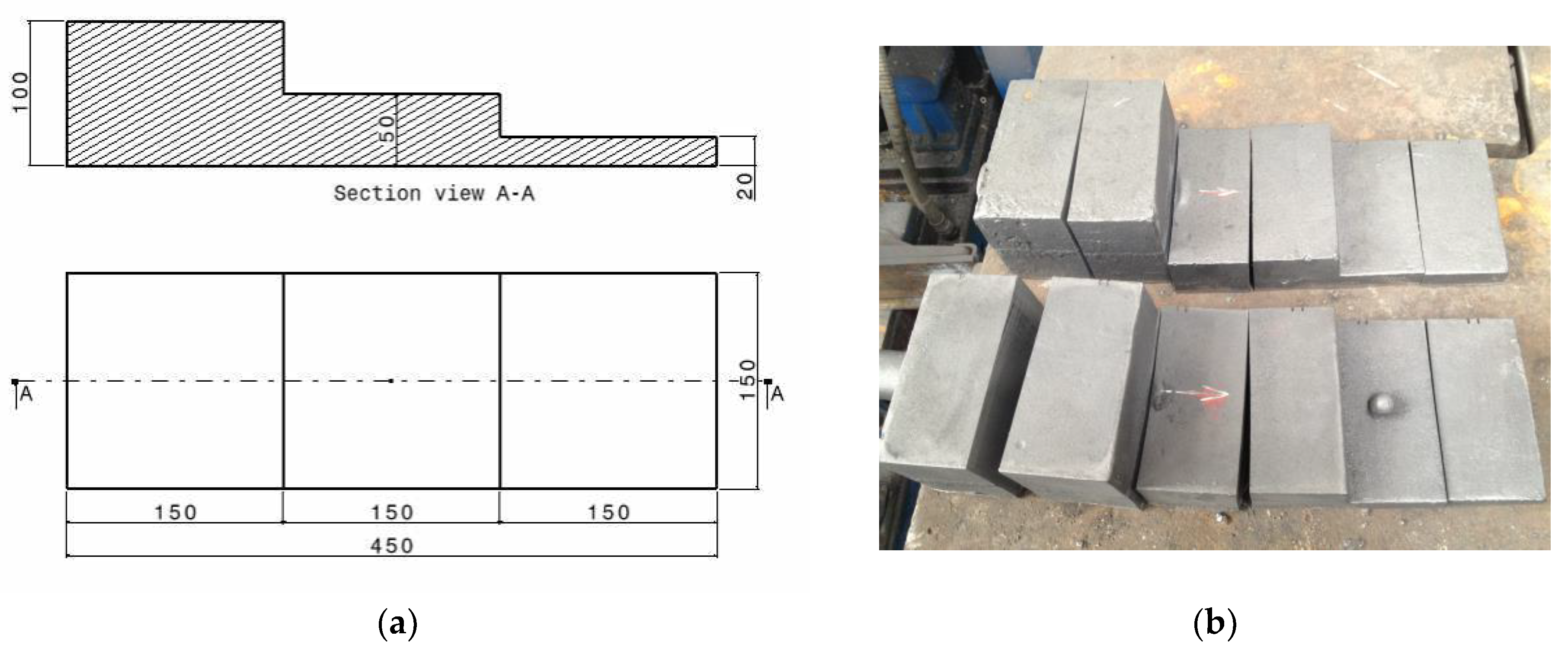
- R-block, with different thicknesses: 100 mm, 50 mm, and 20 mm, to assess the sensitivity of casting hardness to various wall thicknesses and cooling rates—Figure 1. The HB hardness was measured in cut sections in an R-block at each diameter. The measurement was performed using an HPO 3000 (Povazska Bystrica, Slovakia) hardness tester set to a 10 mm diameter test ball, applying a force of 3000 N for 10 s.
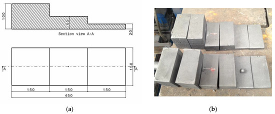 Figure 1. R-block: (a) dimensions; (b) analyzed blocks.
- Tensile strength (Rm) testing was performed on test bars with a diameter of 30 mm using a ZwickRoell (Ulm, Germany) testing machine. The bars for the tensile test were cast separately, in accordance with the foundry’s regulations. Three measurements were taken from each melt.
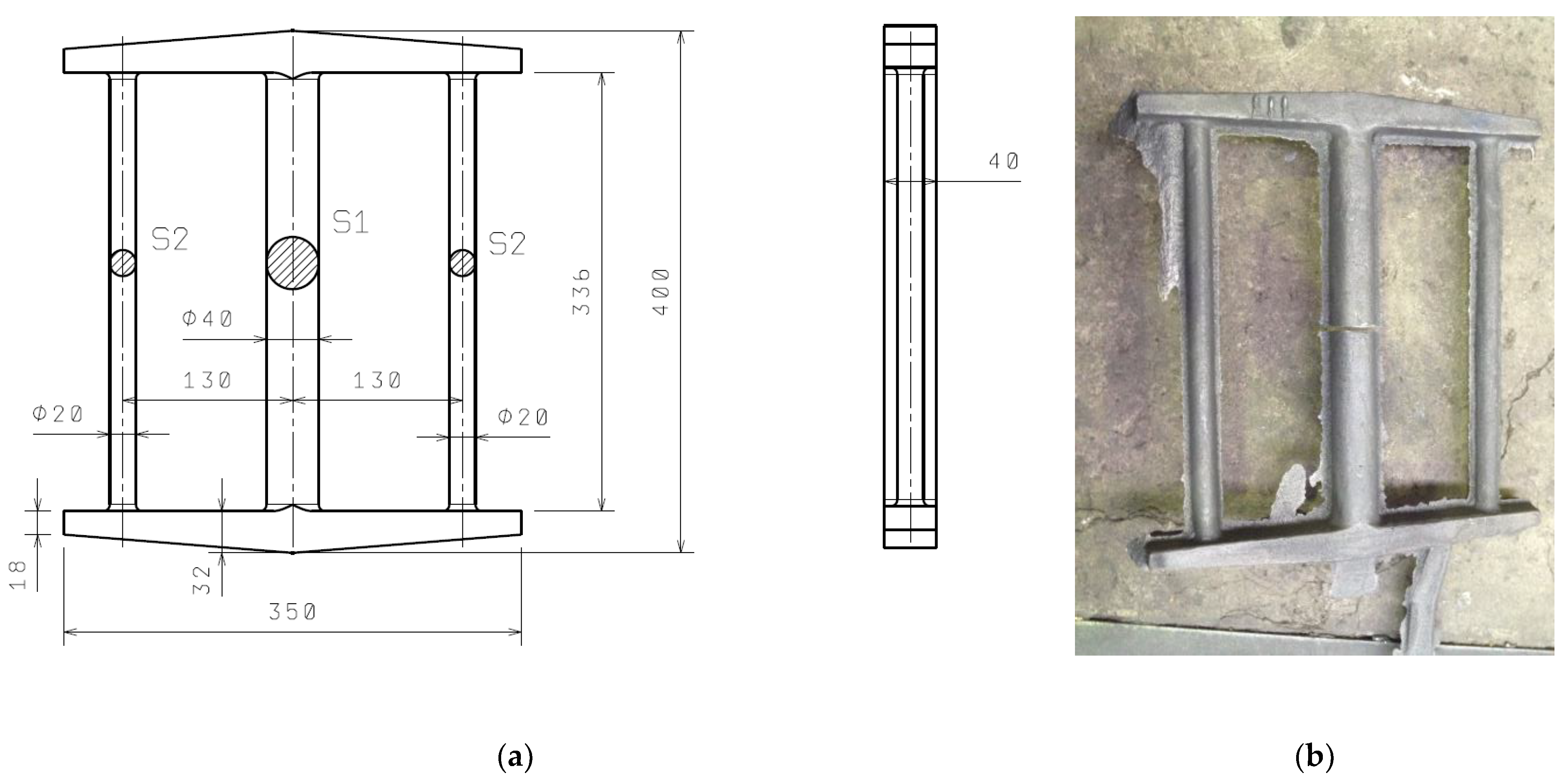
- Sipp test for residual stress measurement, Figure 2. Note that the Sipp test will be discussed later in Section 3.2.2.
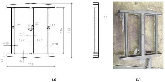
Figure 2.
Sipp test: (a) dimensions; (b) analyzed cast iron.
Figure 2.
Sipp test: (a) dimensions; (b) analyzed cast iron.
- Metallographic analysis was performed on samples taken from the test bars and prepared according to standard procedures.
Individual castings were gravity cast into bentonite molding compound using either a semi-automatic or automatic line. The test molds were prepared in parallel with the molds for casting brake discs, ensuring that the samples were cast under the same conditions, with casting temperatures ranging from 1380 °C to 1400 °C. The prepared molds for casting samples are documented in Figure 3.
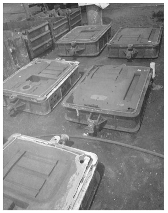
Figure 3.
Prepared molds for casting samples (R-block, Sipp test).
Metallurgical analysis and mechanical properties, including tensile strength and hardness (HB), have been well documented in the literature, with key results summarized in Table 1 and Table 2 [21].

Table 1.
The composition of the charge material and overheating temperature of the melts [21].
Table 2.
The chemical composition and measured mechanical properties [21].
3. Results
3.1. Metallographic Analysis
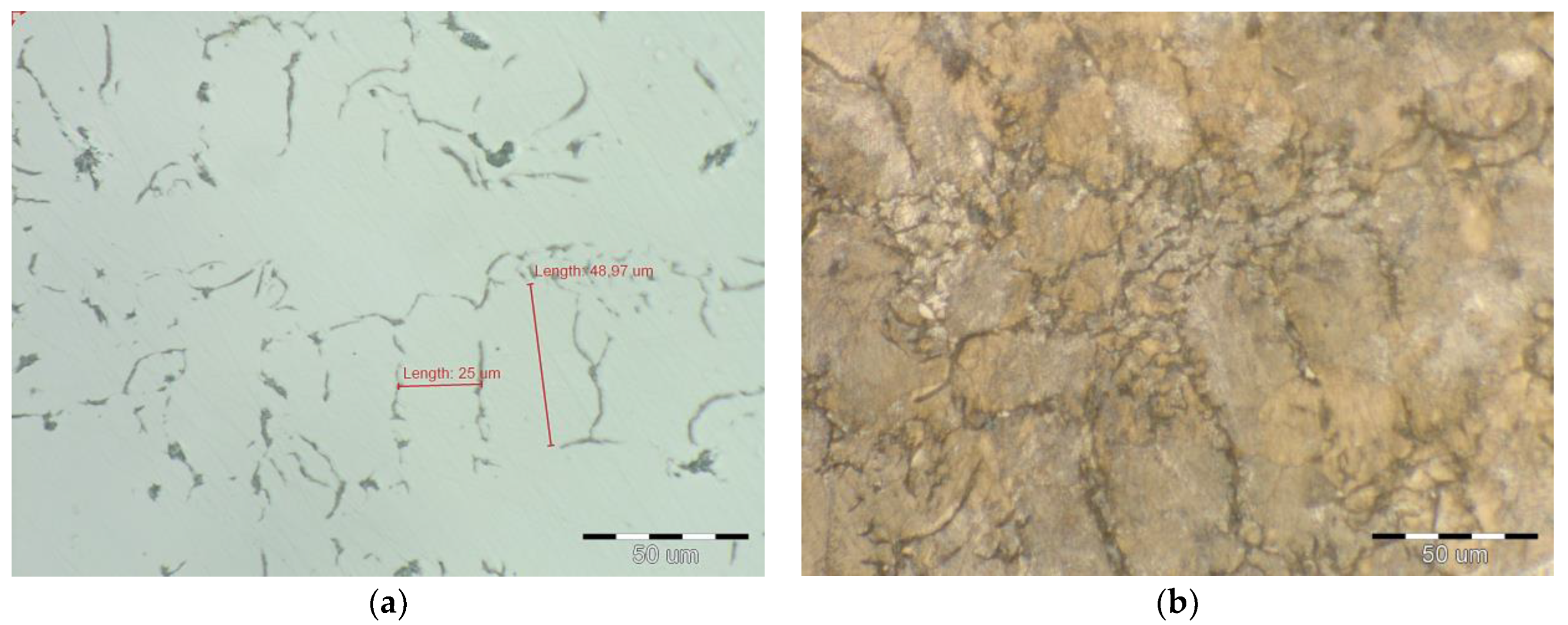
Metallographic analysis was performed using a “Neophot 32” microscope and a “Phenom ParticleX” electron microscope. The samples were etched with 2% Nital. The microstructure of all examined melts displayed a predominantly pearlitic composition, comprising 92% to 96% pearlite, as illustrated in Figure 4—melt No. 1., Figure 5—melt No. 3. Notably, cementite was not detected within the structure of these melts. In contrast, melt No. 5, identified as synthetic gray iron, exhibited a completely pearlitic microstructure, with carbides also being present, as shown in Figure 6. The presence of these carbides contributed to the enhanced hardness observed in this particular gray iron alloy. The microstructure of melt No. 6 (microalloyed FeTi70) is shown in Figure 7 (without carbides). The findings from the metallographic analysis are summarized in Table 3. This exploration of microstructures is crucial for understanding the properties of cast iron, particularly for applications in engineering and materials science.
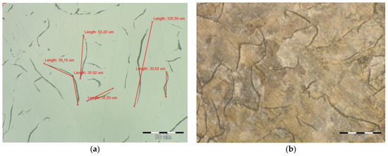
Figure 4.
Microstructure of melt No. 1: (a) magnification 100×; (b) etched Nital 2%.
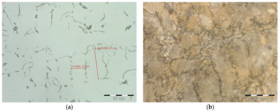
Figure 5.
Microstructure of melt No. 3: (a) magnification 100×; (b) etched Nital 2%.
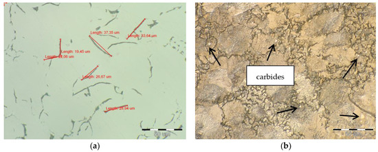
Figure 6.
Microstructure of melt No. 5: (a) magnification 100×; (b) etched Nital 2%.
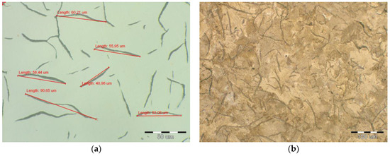
Figure 7.
Microstructure of melt No. 6: (a) magnification 100×; (b) etched Nital 2%.
Table 3.
Metallographic analysis.
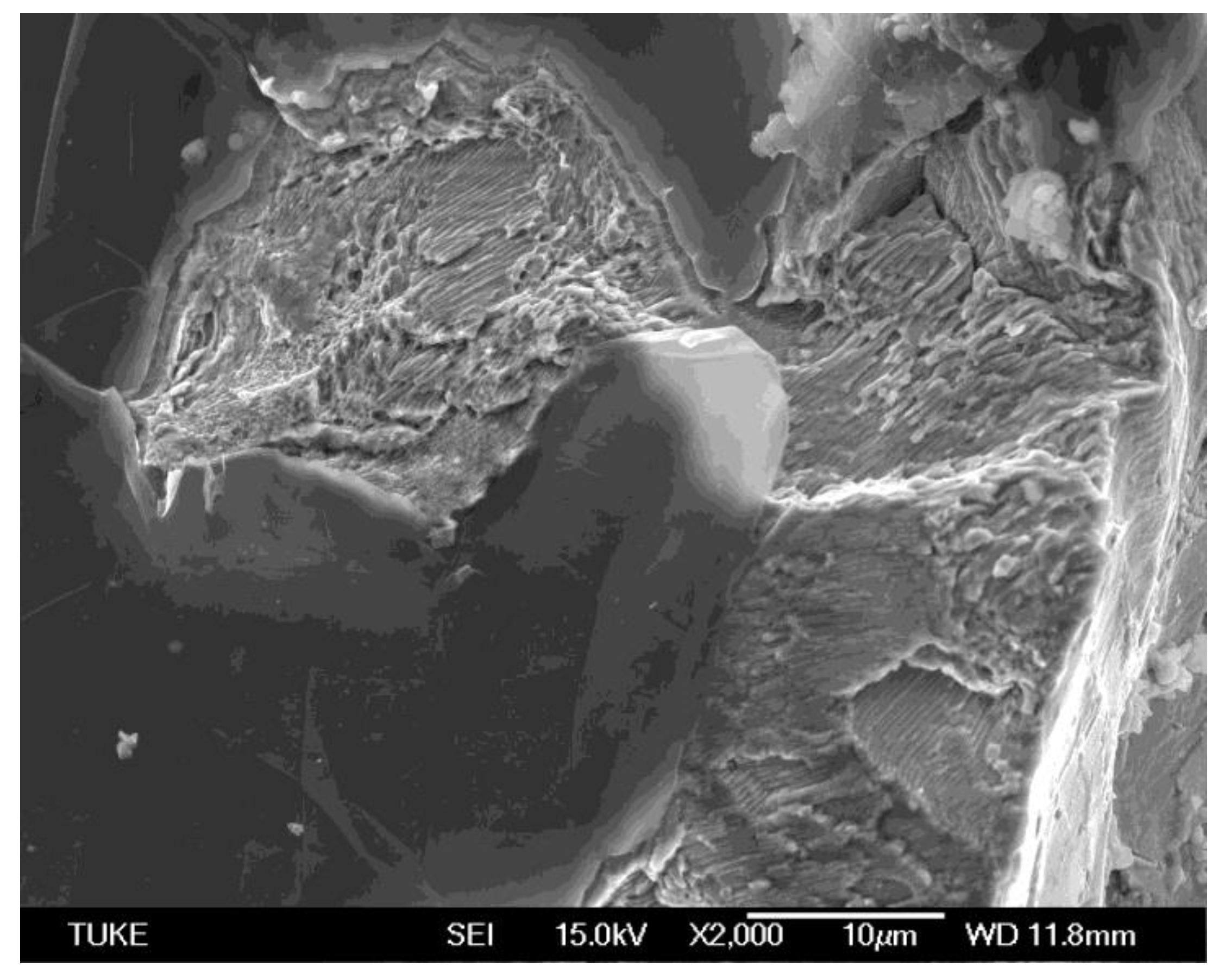
From the results of the electron microscope photographic structures of the tested rod samples (fracture surfaces), cleavage facets due to transgranular fracture are clearly visible, as shown in Figure 8 (Melt No. 1), Figure 9 (Melt No. 3) and Figure 10 (Melt No 6).
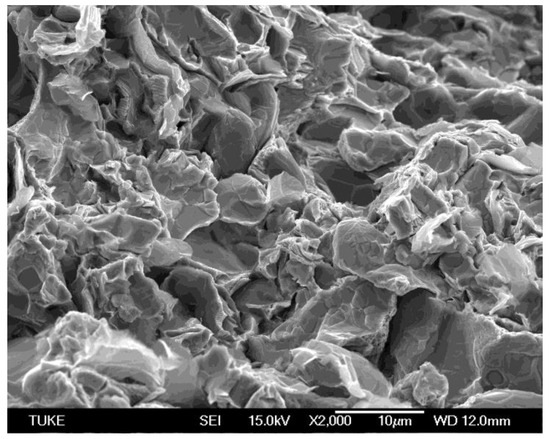
Figure 8.
Microstructure of the fracture surface of melt No. 1 (2000×).
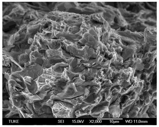
Figure 9.
Microstructure of the fracture surface of melt No. 3 (2000×).

Figure 10.
Microstructure of the fracture surface of melt No. 6 (2000×).
This exploration of microstructures is crucial for understanding the properties of cast iron, particularly for applications in engineering and materials science.
3.2. Analysis of Selected Melts
3.2.1. Hardness HB
Based on the above-mentioned analyzed results, the following three melts were selected (melts 1, 3, and 6 from Table 1 and Table 2):
- A
- Cast iron produced in a traditional way (Melt No. 1);
- B
- Inoculated cast iron (FeSi75), overheated to 1500 °C, microalloyed FeTi70 (Melt No.3);
- C
- Synthetic cast iron, inoculated with FeSi75, overheated to 1500 °C and microalloyed with FeTi70 (Melt No. 6).
The portion of the charge material and the overheating temperature for the selected three melts are given in Table 4.
Table 4.
Selected three melts and their properties.
The main objective of this study was to thoroughly compare the levels of residual stresses and the hardness HB (Brinell hardness). The findings will help clarify the relationship between residual stresses and hardness, ultimately contributing to a more comprehensive understanding of material behavior. The proposed methodology seeks to effectively reduce residual stress levels in synthetic cast iron while ensuring that the necessary hardness is preserved. The findings from this research can be partially validated using data from another study conducted on castings derived from the same melts, as shown in Table 2.
In particular, the HB hardness values obtained from samples taken directly from the stress grid (casting) were compared to the hardness values recorded on the R-block, as illustrated in Figure 1. This comparative analysis enhances our understanding of the hardness characteristics in relation to residual stress. As previously highlighted, hardness plays a crucial role in the subsequent machining processes of castings. Figure 11 illustrates the hardness HB values (with standard deviation) obtained from the castings produced from the analyzed melts 1, 3, and 6 (refer to Table 2), plotted against the thickness of the castings—categorized into thin (20 mm), middle (50 mm), and thick (100 mm) sections. This graphical representation provides valuable insights into how casting thickness influences hardness.
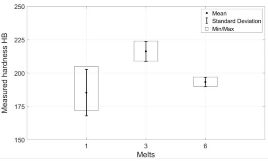
Figure 11.
Dispersion of the hardness HB with standard deviation.
3.2.2. Residual Stresses
Experimental methods for determining residual stresses can be categorized into three fundamental groups based on the extent of damage inflicted on the test specimen:
- Non-destructive;
- Semi-destructive;
- Destructive methods.
In this study, authors used the cutting method, which is classified as a destructive technique, to assess residual stresses in castings. Measurements were conducted on castings featuring a stress grid designed according to Sipp [18,22]. The specific shape and dimensions of this grid are illustrated in Figure 2. The underlying principle of our measurement process involves cutting through a thick bar and subsequently analyzing the dimensional changes that occur in the casting as a result of the inherent residual stresses. This approach allows us to gain valuable insights into the stress distribution within the material. The residual stresses arise due to the higher cooling and shrinkage rate of the thick bar (marked 1M) in the temperature region of elastic deformation compared to the thinner bars (marked 2L and 2R), which are nearly cooled at that time, preventing the thick bar from shrinking (the marking is shown in Figure 12).
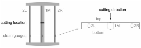
Figure 12.
Position of the measuring sensors for the Sipp test.
After the casting has cooled, tensile and compressive residual stresses are induced in the thick bar (1M) and thin bars (2L, 2R), respectively. Based on the data obtained, the propensity of the alloy to form residual stresses can be assessed. The Sipp test is based on the conditions of static equilibrium in the volume of the lattice according to Equation (1); is plus (tensile), while is minus (compressive). Therefore, Equation (1) is as follows:
where:
—the uniaxial tensile stress in the thick bar 1M;
—uniaxial compressive stress in the thin bar (2L, 2R);
A1—cross-sectional area of the thick bar;
A2—cross-sectional area of the thin bar.
The dimensions in Figure 2 show that the cross-sectional area of the thick bar is 4 times greater than the cross-sectional area of the thinner bar. Based on the above fact, Equation (1) can be modified to form (3) by considering Hooke’s law:
where:
—strain in the thick bar;
—strain in the thin bar;
E—Young’s modulus of the casting material, which is the same for both bars.
From Equation (2), it follows that there is a linear dependence between the principal strains and in the elastic deformation region. The authors of this paper decided to use the strain gauge method to measure the strains, which allows us to directly register the proportional strains on the surface of the specimen at the measured location. The advantage of the chosen method is that the strain gauge can be placed at any location on the surface of the casting.
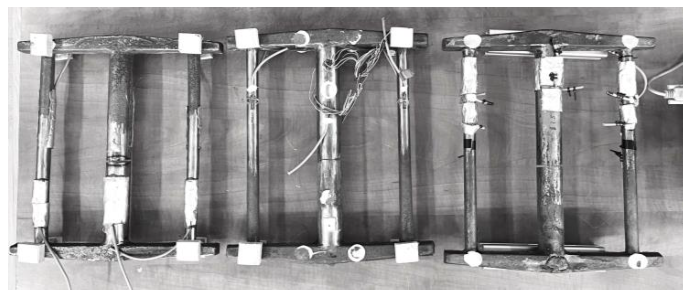
The Sipp grid is designed to induce uniaxial stresses in three parallel bars. The standard procedure for measuring tensile/compressive stresses, with the exception of bending, is a half-bridge connection of two strain gauges placed in the same cross-section on opposite sides. The advantage of this configuration is that it allows the evaluation of the value corresponding to uniaxial stress only. As this case involves measurements on castings where thermal processes play a large role, the authors decided to use a quarter-bridge configuration. Assuming the occurrence of only uniaxial stresses, the measured values at two opposite locations in the same cross-section should be approximately similar. The advantage of the quarter-bridge configuration is that the measured values can provide very important information about, for example, the presence of the bending effect. The chosen procedure proved to be appropriate because experimental measurements also identified bending effects caused by gradual cooling of the casting. A schematic of the specimen with the location of the strain gauges for the experimental measurement of residual stresses is shown in Figure 12. The locations of the strain gauges were chosen in the same cross-sections as seen in the figure. The effect of temperature change during the residual stress measurement can be neglected because the room temperature was constant and the strain gauges were applied at a sufficient distance from the cutting location. Strain gauges of type 1-LY11-10/120 (HBM, Darmstadt, Germany), Quantum MX840 measuring apparatus (HBM, Germany), and CatmanAP evaluation software (ver. 5.0.1, HBM, Darmstadt, Germany) were used for the measurements [23]. As mentioned before, the residual stresses were evaluated based on the measured strains registered by the strain gauges. Figure 13 shows a view of the castings (Sipp test) with applied strain gauges after cutting. The casting was positioned so that the sprue system was on the top during cutting.
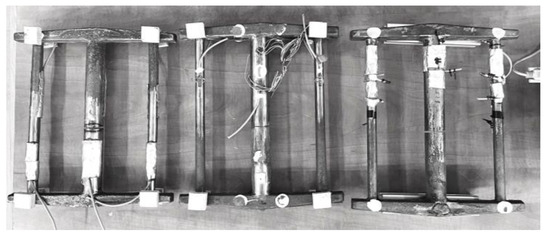
Figure 13.
View of all analyzed samples after cutting.
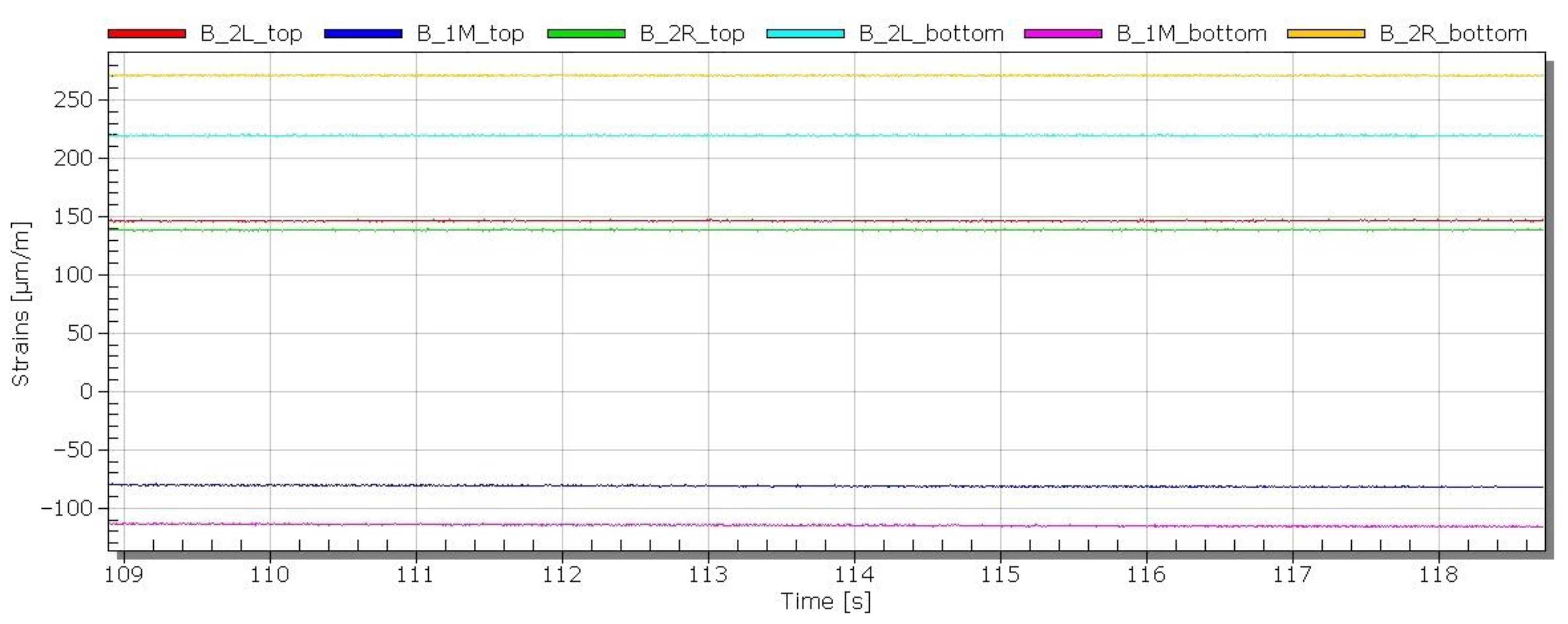
In Figure 14, the time record of the strains registered during the cutting process is documented. The residual stresses arise due to the higher cooling and shrinkage rate of the thick bar (marked 1M).
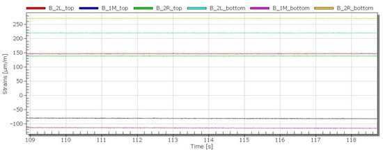
Figure 14.
Time recording of strains after cutting sample B (casting).
Since the measured values were obtained in a quarter-bridge connection, they consider not only the effect of the uniaxial strain on the bars but also the bending effect due to the cooling of the casting. Table 5 shows the measured values of the strains read at the end of the measurement.
Table 5.
Measured strains after cutting the castings.
Since the data were read at the end of the measurement (after the casting was cut), it can be concluded that the different values at the top and bottom of the bars are due to the temperature effect in the cooling process of the casting. From the measured data in the upper and lower fibers in the same cross-section when considering tensile and bending stresses, only the axial stress component can be determined from the stress distribution over the height of the cross-section; see Table 6. The measured positive value means that after the casting was cut, the bar, which was compressed before cutting, elongated. That is, a positive value of the measured strains corresponds to compressive residual stresses and, conversely, a negative value corresponds to tensile residual stresses.
Table 6.
Values of strains in cast rods excluding bending.
According to Sipp, residual stresses in castings are evaluated by comparing the elongation of the bars after the casting has been cut. The bar elongation is directly related to the proportional deformation; therefore, the strain gauge method chosen by the authors can be considered appropriate. Although only three specimens (one from each melt) were used for the measurements, the analysis of the experimentally measured data confirms, among other things, the real-life experience that there is a different stress distribution along the height of the casting during casting due to temperature effects, which can also be considered as a valuable finding.
4. Conclusions
Based on the data obtained from our experiments, we can confidently draw certain conclusions:
- (1)
- By comparing castings with added Ti made from pig iron and steel scrap (synthetic cast iron), lower levels of residual stresses were measured on the synthetic alloy.
- (2)
- In the samples with added Ti (No. 3 and No. 6), there was a significant decrease in the residual stress levels compared to the casting without added Ti (No. 1); see Table 6. Microalloying with FeTi70 positively affects the sensitivity of the dispersion of the mechanical properties of cast iron due to the change in the wall thickness of the casting, as well as the reduction in residual stresses. In synthetic cast iron (melt No. 5), carbides were observed in the structure (Figure 4). By microalloying Ti, their presence in the structure of synthetic cast iron (melt No. 6) was not confirmed, which also has a positive effect on residual stresses.
- (3)
- Based on the measured values in the upper and lower fibers for all three castings, it can be concluded that residual stresses not only from tension/compression but also from bending occurred during the cooling process; see Table 5.
- (4)
- From the analysis of the hardness measured on the R block, it can be concluded that the addition of FeTi70 caused a decrease in the HB hardness of synthetic cast iron and the dispersion of HB hardness in the thick part of the casting compared to the thin part was very small (less than 5%; see Figure 11).
The experimentally determined values confirmed the authors’ theoretical assumptions on how residual stress levels can be reduced for synthetic cast iron (scrap steel with Ti addition) compared to cast iron made from pig iron.
The economic aspect of synthetic cast iron production is also important. The economic saving compared to conventional pig iron production is almost 40%, but in addition, the processing of steel scrap leads to a reduction in energy consumption in terms of feedstock [24,25].
The reintroduction of synthetic cast iron production in an already existing foundry is time-efficient and economically feasible and there is a possibility of returning to pig iron production in case of non-availability of steel scrap.
Author Contributions
Conceptualization, P.F. and A.P.; methodology, P.F., M.P. and A.P.; validation, J.B. and M.P.; formal analysis, P.F. and M.P.; resources, J.B. and A.P.; data curation, P.F. and A.P.; writing—original draft preparation, P.F.; writing—review and editing, J.B., M.P. and A.P.; visualization, J.B. and M.P.; project administration, A.P.; funding acquisition, P.F. All authors have read and agreed to the published version of the manuscript.
Funding
This research was funded by the projects VEGA 1/0597/23 Possibilities of application of laser additive technologies in the restoration of functional surfaces and KEGA 024TUKE-4/2025 Hybrid education of students for the current needs of the automotive industry.
Data Availability Statement
The original contributions presented in this study are included in the article. Further inquiries can be directed to the corresponding author.
Acknowledgments
This work was supported by the Scientific Grant Agency of The Ministry of Education of the Slovak Republic No. VEGA 1/0001/25, VEGA 1/0516/22, VEGA 1/0359/25, VEGA 1/0597/23, APVV-22-0580, KEGA 024TUKE-4/2025.
Conflicts of Interest
The authors declare no conflicts of interest.
References
- Riposan, I.; Chisamera, M.; Stan, S. Enhanced quality in electric melt grey cast irons. ISIJ Int. 2013, 53, 1683–1695. [Google Scholar] [CrossRef]
- Kukartsev, V.A.; Cherepanov, A.I.; Kukartsev, V.V.; Mikhalev, A.S.; Makarchuk, I.Y. Increasing the Efficiency of Production of Synthetic Cast Iron. Key Eng. Mater. 2021, 904, 3–8. [Google Scholar] [CrossRef]
- Futas, P.; Pribulova, A.; Petrik, J.; Pokusova, M.; Junakova, A. The study of synthetic cast iron quality made from steel scrap. In Proceedings of the 18th International Multidisciplinary Scientific GeoConference Surveying Geology and Mining Ecology Management, Albena, Bulgaria, 2–8 July 2018; pp. 321–329. [Google Scholar] [CrossRef]
- Snigir, A.N.; Savitsky, E.M.; Saikin, V.T.; Petrov, G.B. Control over the process of formation of the structure and properties of cast iron by thermal analysis method. Thermochim. Acta 1985, 93, 657–660. [Google Scholar] [CrossRef]
- Dey, A.K. Energy efficiency model for induction furnace. IOP Conf. Ser. Mater. Sci. Eng. 2018, 302, 012047. [Google Scholar] [CrossRef]
- Sarkar, T.; Bose, P.K.; Sutradhar, G. Mechanical and tribological characteristics of copper alloyed austempered gray cast iron (AGI). Mater. Today Proc. 2008, 5, 3664–3673. [Google Scholar] [CrossRef]
- Kaczorowski, M.; Myszka, D. On the differences between mechanical properties and structure of ductile iron castings austempered using conventional and direct method. Int. J. Manuf. Sci. Technol. 2005, 7, 33–39. [Google Scholar]
- Medyński, D.; Janus, A. Effect of Cr, Mo and Al on Structure and Selected Mechanical Properties of Austenitic Cast Iron. Arch. Foundry Eng. 2019, 19, 39–44. [Google Scholar] [CrossRef]
- Hanqi, H.; Qujie, Z. Effect of Nitrogen on Matrix Structure of Gray Cast Iron. Acta Metall. Sin. (Engl. Ed.) Ser. A 1993, 6, 370–372. [Google Scholar]
- Kagawa, A.; Okamoto, T. Partition of Alloying Elements in Freezing Cast Irons and Its Effect on Graphitization and Nitrogen Blowhole Formation; The Institute of Scientific and Industrial Research Osaka University: Ibaraki, Japan, 2011. [Google Scholar]
- Callister, W.D. Materials Science and Engineering; Department of Metallurgical Engineering, The University of Utah: Salt Lake City, UT, USA, 2009; ISBN 978-0-471-73696-7. [Google Scholar]
- Collini, L.; Nicoletto, G.; Konecna, R. Microstructure and mechanical properties of pearlitic gray cast iron. Mater. Sci. Eng. 2008, 488, 529–539. [Google Scholar] [CrossRef]
- Wilberfors, F.; Svensson, I. The effect of nitrogen and inoculation on the tensile properties and microstructure of cast iron lamellar. Key Eng. Mater. 2010, 457, 114–119. [Google Scholar] [CrossRef]
- Futas, P.; Jelč, I.; Vasková, I.; Fedorko, G.; Molnár, V.; Kačmáry, P. The Gist of thermal stresses of cast iron castings. Manuf. Technol. 2013, 13, 173–178. [Google Scholar]
- Balasingh, C.; Seshadri, M.R.; Srinivasan, M.N.; Ramaseshan, S. Effect of carbon equivalent and inoculation on residual stresses in grey iron castings. J. Mech. Work. Technol. 1984, 9, 53–66. [Google Scholar] [CrossRef]
- Johnson, E.M.; Watkins, T.R.; Schmidlin, J.E.; Dutler, S.A. A Benchmark Study on Casting Residual Stress. Metall. Mater. Trans. A 2012, 43, 1487–1496. [Google Scholar] [CrossRef]
- Keste, A.A.; Gawande, S.H.; Sarkar, C. Design optimization of precision casting for residual stress reduction. J. Comput. Des. Eng. 2016, 3, 140–150. [Google Scholar] [CrossRef]
- Marberg, A.; Pal, J. Residual Stresses in Cast Iron, Diploma Work No. 200/b, Chalmers University of Technology, Gothenburg, Sweden. Available online: https://odr.chalmers.se/server/api/core/bitstreams/23f255d3-d43c-4996-8c45-4691960a15f3/content (accessed on 30 March 2025).
- Tian, G.; Bu, K.; Tian, Q.; He, J. A Casting Shrinkage Prediction Method Based on Model Automated Self-correction Strategy. Int. J. Met. 2024, 18, 1052–1061. [Google Scholar] [CrossRef]
- Motoyama, Y.; Shiga, H.; Sato, T.; Sato, T.; Kambe, H.; Yoshida, M. Effects of Recovery Behavior and Strain-Rate Dependence of Stress–Strain Curve on Prediction Accuracy of Thermal Stress Analysis During Casting. Metall. Mater. Trans. A 2017, 48, 2960–2970. [Google Scholar] [CrossRef]
- Futas, P.; Pribulova, A.; Petrik, J.; Blasko, P.; Junakova, A.; Sabik, V. Metallurgical Quality of Cast Iron Made from Steel Scrap and Possibilities of Its Improvement. Metals 2023, 13, 27. [Google Scholar] [CrossRef]
- Gedeonová, Z.; Vondrák, V. Kontrola Kvality Odliatkov; Alfa: Bratislava, Slovakia, 1983; ISBN 6373883. [Google Scholar]
- Available online: https://www.hbm.com/ (accessed on 30 March 2025).
- Yang, Y.; Zhang, L.; Yuan, Y.; Sun, J.; Che, Z.; Qiu, Z.; Du, T.; Na, H.; Che, S. Muti-objective optimization on energy consumption, CO2 emission and production cost for iron and steel industry. J. Environ. Manag. 2023, 3471, 119102. [Google Scholar] [CrossRef] [PubMed]
- Turakulov, M.; Tursunov, N.; Yunusov, S. New concept of cast iron melting technology in induction crucible furnace. E3S Web Conf. 2023, 401, 01060. [Google Scholar] [CrossRef]


Disclaimer/Publisher’s Note: The statements, opinions and data contained in all publications are solely those of the individual author(s) and contributor(s) and not of MDPI and/or the editor(s). MDPI and/or the editor(s) disclaim responsibility for any injury to people or property resulting from any ideas, methods, instructions or products referred to in the content. |
© 2025 by the authors. Licensee MDPI, Basel, Switzerland. This article is an open access article distributed under the terms and conditions of the Creative Commons Attribution (CC BY) license (https://creativecommons.org/licenses/by/4.0/).