Article

Gradient Dual-Phase Structure Design in Brass: A New Strategy for Balancing Mechanical and Tribological Properties

by
Jing Han
1,2,*,
Tao Zhang
1,
Bin Zhang
3,
Jing Zhang
4 and
Jiyun Zhao
1,2,*
1
School of Mechanical and Electrical Engineering, China University of Mining and Technology, Xuzhou 221116, China
2
State Key Laboratory of Intelligent Mining Equipment Technology, China University of Mining and Technology, Xuzhou 221116, China
3
State Key Laboratory of Fluid Power and Mechatronic Systems, Zhejiang University, Hangzhou 310027, China
4
College of Materials Science and Engineering, Hohai University, Nanjing 210024, China
*
Authors to whom correspondence should be addressed.
Metals 2025, 15(5), 515; https://doi.org/10.3390/met15050515
Submission received: 1 April 2025 / Revised: 27 April 2025 / Accepted: 28 April 2025 / Published: 1 May 2025

Abstract

:
This study introduces a novel gradient dual-phase structure design in brass, achieved through ultrasonic severe surface rolling (USSR) processing, which enables an unconventional asymmetric bilayer structure—comprising a hardened surface layer (>1 mm thick) and a ductile substrate—distinct from conventional hard-soft-hard sandwich configurations in gradient nanostructured materials. Microstructural characterization reveals a gradient dual-phase (α + β′) structure in the hardened layer, progressively transitioning into a homogenized dual-phase structure in the substrate. This unique architecture endows the USSR brass with exceptional mechanical properties, including a yield strength of 582.4 ± 31.0 MPa, ultimate tensile strength of 775.3 ± 33.9 MPa, and retained ductility (9.3 ± 1.0%), demonstrating an outstanding strength-ductility synergy. The USSR brass also demonstrates superior wear resistance with a 42.32% reduction in wear volume and 40.82% decrease in coefficient of friction compared to its as-received counterpart under oil lubrication. This architectural paradigm establishes a robust framework for engineering high-performance brass that simultaneously achieve an exceptional strength-ductility balance and enhanced wear resistance.

1. Introduction

Brass, a copper-zinc alloy with zinc as the primary alloying element (Cu content: 55–96%), is generally categorized into two groups: plain brass (Cu-Zn binary alloys) and complex brass (modified with additional elements like Mn, Al, or Si for enhanced performance). Characterized by excellent mechanical properties, superior corrosion resistance, remarkable wear resistance, and favorable workability, brass ranks as the most widely used structural copper alloy. High-performance complex brass is indispensable in critical engineering areas including rail transportation, construction machinery, hydraulic systems, and aerospace applications, serving as a vital structural material for demanding service conditions. For example, the addition of manganese to brass enhances its strength, hardness, and wear resistance through solid solution strengthening, making it a preferred wear-resistant material for applications such as tribological pair in high-pressure pump, bearing sleeves, gears, and valve cores. This necessitates simultaneous consideration of multiple performance indicators—including wear resistance, strength, and ductility—in material optimization studies. However, material properties often exhibit trade-off relationships; for instance, strength enhancement typically accompanies ductility reduction. This phenomenon, known as the strength-ductility paradox, represents a critical scientific challenge in materials science and remains a hot topic in frontier research.
The properties of materials are not only related to their chemical composition but also closely associated with their microstructure. Therefore, meticulously designing microstructures in metallic materials has proven to be an effective approach for improving mechanical properties and other characteristics. Over the past half-century, numerous microstructure construction strategy, such as fine/ultrafine grains [1,2], nanostructures [3], gradient nanostructures [4,5], nanotwins [6,7], and heterostructures [8,9], have been successfully proposed, significantly enhancing the multiple properties of the metallic materials. These microstructural innovations have also been applied to optimize the properties of brass. Gu et al. reported the ultrafine-grained Cu-30Zn (wt%) alloy fabricated by equal channel angular pressing (ECAP) achieved remarkable yield strength of 590 MPa, yet exhibited negligible uniform elongation [10]. To recover ductility, controlled post-annealing treatments were systematically implemented to coarsen grains. The experimental results revealed an optimal balance between ultimate tensile strength (565 MPa) and uniform elongation (20%) when the grain size was optimized to 3.8 μm. Chen et al. employed ECAP combined annealing to obtain ultrafine-grained structures with an average grain size of 640 nm in Cu-38Zn (wt%) alloy, resulting in a significant yield strength improvement to 565 MPa while maintaining a good uniform elongation of 18.4% [11]. These studies demonstrate the critical role of grain boundary engineering in resolving the strength-ductility trade-off of the brass.
The fabrication of gradient nanostructures has proven to be an effective strategy for achieving excellent strength-toughness synergy for metallic materials, including copper and its alloys [12,13,14,15]. This structural design, featuring a gradient grain size distribution from the surface to the core, effectively overcomes the inherent ductility limitation of conventional nanostructured/ultrafine-grained metallic materials. Fang et al. successfully engineered gradient nanograined pure copper through surface mechanical grinding treatment (SMGT) [5]. During tensile deformation, the strain localization phenomenon, the intrinsic drawback limiting the tensile ductility of conventional nanostructured metals, was effectively mitigated through the grain boundary mediated plasticity. Lu et al. fabricated gradient nanostructure in H62 brass using laser shock peening (LSP) [16]. This technique induced extremely small nanograins (down to <10 nm) at the surface, mixed by localized amorphous structure formation. Consequently, the simultaneous enhancement of strength and ductility in brass was obtained. Wang et al. prepared a thickness gradient nanograined layer in Cu-30%Zn (wt%) alloy through combined route of multiple-pass friction stir processing (FSP) and rotationally accelerated shot peening (RASP) [17]. This advanced manufacturing approach achieved a remarkable yield strength enhancement exceeding fourfold, accompanied by preserved ductility. Quantitative analysis revealed that the synergistic strengthening effect contributed over 33% of the total yield stress.
The gradient nanostructured surface layer also possesses superior tribological performance through strategically tailoring microstructure. Chen et al. found that the implementation of a gradient nanograined surface layer in Cu reduced the friction coefficient from 0.64 (conventional coarse-grained counterpart) to 0.29 under dry sliding conditions [18]. Due to this low friction, the wear volume was also significantly decreased [19]. The good tribological performance was also found in gradient nanostructured Cu-Al alloy [20].
The exceptional strength-plasticity synergy and wear resistance imparted by gradient nanostructures open new avenues for developing high-performance, long-lifespan structural and tribological components. However, due to limitations in current fabrication technologies, achieving gradient nanostructured surface layer on complex-shaped component surfaces remains a formidable challenge. Furthermore, the thickness of the gradient nanostructured surface layer achieved by conventional techniques is relatively limited, restricting their effectiveness in improving the overall performance of thick-walled components. Recently, we developed an ultrasonic severe surface rolling (USSR) to prepare thick and high-performance gradient nanostructured surface layer [21]. The high-frequency ultrasonic impact loading (20~30 kHz) in the USSR process generates instantaneous strain rates reaching 105 s−1 [22]. This strain-rate significantly exceeds those attained by conventional surface severe plastic deformation techniques, such as surface mechanical attrition treatment (SMAT, 102~103 s−1), SMGT (103 s−1), and surface mechanical rolling treatment (SMRT, 103~104 s−1) [23]. By integrating high static stresses with ultrasonic impact loading, the USSR process achieves unprecedented hardened layer thickness. This facilitates gradient nanostructure engineering in thick-walled components for enhancement in strength-ductility combination. The USSR processed Cu-38%Zn (wt%) alloy demonstrated an extremely thick gradient surface layer (1.1 mm) [24]. This manifests in excellent strength-ductility balance (467.5 MPa in yield strength and 10.7% in uniform elongation).
In this study, a novel strategy for fabricating a gradient dual-phase structure in a complex brass is proposed, aiming to simultaneously enhance its mechanical and tribological properties. The USSR is employed to fabricate this unique structure. Comprehensive microstructural characterization was performed to elucidate the gradient dual-phase structure, and establish a correlation between the engineered microstructure and the enhanced mechanical and tribological properties. This research establishes a novel methodology for optimizing the properties of parts, thereby addressing critical wear challenges, such as those faced by plunger sleeve assemblies in high-pressure axial piston pumps.

2. Materials and Methods

The as-received material consisted of commercially ZY331604 brass bars (Ø30 mm, Ningbo Zhengyuan Copper Alloy Co., Ningbo, China) from which 2 mm-thick plates were sectioned along the longitudinal axis. The chemical composition of the brass was measured through X-ray Fluorescence Spectrometer (XRF, Malvern Panalytical, Malvern, UK), and listed in Table 1. Specimen preparation involved sequential surface conditioning through mechanical grinding with progressively finer sandpapers culminating in 800-grit surface finish. USSR was subsequently implemented on the brass plate through four consecutive passes under controlled processing parameters, as shown in Figure 1. The primary processing parameters were configured as follows: ultrasonic frequency of 23 kHz, amplitude of 5 μm, static pressure of 0.4 MPa, velocity of 2 m/min, and feed interval of 0.1 mm. A cemented carbide ball with a diameter of 14 mm was used as the rolling tool. Cutting oil was employed during the USSR processing for lubrication and cooling. During the USSR processing, the tip processed the plate via linear scanning, as illustrated by the arrow trajectory in Figure 1. The tip could freely roll to form rolling contact with the plate, which reduced surface damage formation. Following the surface treatment, the samples underwent light grinding with 2000-grit sandpaper to eliminate surface contaminants and mitigate potential surface damage induced during processing.
The as-received sample were subjected to multiple characterization employing scanning electron microscopy (SEM, TESCAN MAIA3, Brno, Czech Republic) with energy-dispersive spectroscopy (EDS), X-ray diffraction (XRD, RIGAKU Smartlab, Tokyo, Japan), and electron backscatter diffraction (EBSD, EDAX Hikari Plus, Mahwah, NJ, USA). SEM specimens were prepared following the standard metallographic preparation protocol, involving sequential grinding with sandpapers and final mechanical polishing. For EBSD specimens, supplementary electrochemical polishing was conducted.
Quasi-static uniaxial tensile tests were conducted using a universal testing machine (SUNS UTM4204X, Shenzhen, China). The tests were performed in displacement control mode at a constant velocity of 0.5 mm·min−1. Specimen geometry features a reduced section of 7.50 mm gauge length and with 2 × 2 mm square cross-section. The tensile specimens for USSR brass were fabricated using electrical discharge machining from processed plates, with subsequent grinding to improve quality of the machined surfaces. Therefore, only one surface of the tensile sample underwent USSR. A similar preparation process was implemented for fabricating tensile specimens from the as-received brass. Three independent tensile tests were conducted to ensure data repeatability. Subsequently, depth-dependent microhardness profiling was conducted on cross-section perpendicular to the treated surface. Vickers hardness measurements were obtained under an applied load of 0.98 N with a dwell time of 10.0 s. The reported hardness values represent the average of at least three replicate measurements.
A tribological investigation was performed using a Lanzhou Huahui MS-M9000 (Lanzhou, China) multi-functional tribometer operating in ball-on-disk reciprocating configuration according to ASTM G 133-05 standard [25]. The experimental parameters were controlled as follows: slide stroke of ~2.5 mm, frequency of 5.0 Hz, normal load of 15 N, and test duration of 3600 s. The counterface material consisted of an alumina ball with a nominal diameter of 6.00 mm. This result in a maximum contact stress of 1.4 GPa calculated through Hertz contact theory. Lubrication was provided by ISO VG 46 hydraulic oil (Sinopec Group Co., Ltd., Beijing, China), which is generally used in high-pressure plunger pump. All tests were repeated three times to verify repeatability. Post-test analysis included detailed characterization of wear scars using SEM coupled with EDS.

3. Results

3.1. Microstruction of the As-Received Sample

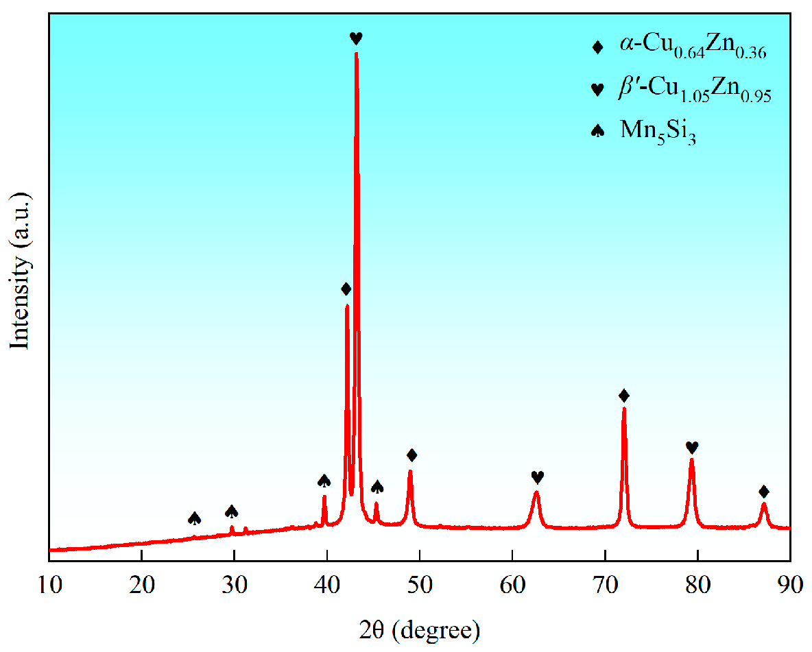
Based on the comprehensive analysis of SEM, EDS, XRD, and EBSD results (Figure 2, Figure 3 and Figure 4), the as-received sample exhibits a dual-phase microstructure consisting of α-Cu0.64Zn0.36 phase with face-centered cubic (FCC) lattice and β′-Cu1.05Zn0.95 phase with body-centered cubic (BCC) lattice. The α phase is a Cu-based solid solution primarily alloyed with Zn, while the β′ phase corresponds to a CuZn electron compound [26]. EBSD inverse pole figure (IPF) mapping and phase distribution mapping indicate that the α phase predominantly displays a lath-shaped morphology. Quantitative EBSD analysis reveals that the β′ phase has a volume fraction of 53.2%, significantly higher than that observed in conventional Cu-Zn binary brasses with comparable Zn content [11,27]. This notable discrepancy may be attributed to the addition of Al element, which alters the phase equilibrium. The α phase has an average grain size of 9.5 μm, marginally finer than the 12.8 μm grains of the β′ phase. A small number of twins are found within the α phase. The Kernel Average Misorientation (KAM) mapping analysis of the as-received sample exhibits high KAM value, indicative of high dislocation density, as indicated in Figure 4c. Additionally, SEM imaging (Figure 2a) identifies a distinct phase with contrasting morphology. EDS mapping confirms its enrichment in Si and Mn, and XRD pattern (Figure 3) identifies it as Mn5Si3 silicide with hexagonal crystal lattice.

3.2. Microstruction of the USSR Sample

Figure 5 shows the cross-section EBSD analysis of the USSR sample. As illustrated in Figure 5a,b, the near-surface region exhibits significant grain refinement in both the α phase and β′ phase. A distinct grain size gradient is observed, with coarser grains developing at greater depths. No significant increase in twin density was observed compared to the as-received sample. Additionally, a depth-dependent gradient in KAM values is evident (Figure 5c). The average KAM value (θ) can correlate with geometrically necessary dislocation (GND) density ρ G N D through the following relationship [13]:
ρ G N D = 2 θ μ b
where μ is the EBSD scanning step size, and b represents the magnitude of the Burgers vector, taken as 0.261 nm for the α phase and 0.255 nm for the β′ phase. To quantify this evolution, the EBSD region was divided into nine equally spaced subdomains along the depth. The calculated GND density for each subdomain reveals a monotonic decrease in dislocation density with increasing depth, as indicated in Figure 6. Critically, the near-surface layer exhibits significantly elevated GND density in both the α phase and β′ phase. The maximum GND density reaches 41.7 × 10¹⁴ m−2 in α phase and 16.1 × 10¹⁴ m−2 in the β′ phase, surpassing those of the as-received sample by factors of 2.9 and 2.5, respectively. Notably, the α phase undergoes a more pronounced dislocation density enhancement compared to the β′ phase. This gradient dislocation-density profile, coupled with the gradient grain size, conclusively demonstrates the formation of a gradient dual-phase structure in the USSR sample. Figure 7 shows the cross-section SEM image and corresponding EDS element mapping of the USSR sample, revealing no evidence of gradients in chemical composition.
Therefore, the USSR brass plate manifests an integrated multiscale architecture spanning macroscopic to microscopic regimes. Macroscopically, a distinctive bilayer architecture is observed comprising a hardened surface layer (>1 mm thickness) and a soft substrate layer, as illustrated in Figure 1, deviating from conventional hard-soft-hard sandwich structures typically employed in gradient-nanostructured materials [23]. Microstructurally, the hardened layer features a gradient dual-phase microstructure transitioning to homogeneous dual-phase microstructure in the substrate. This asymmetric architecture exhibits superior compatibility with geometrically complex components (e.g., plunger bushings, valve plates in hydraulic systems) during industrial-scale processing.

3.3. Mechanical Properties

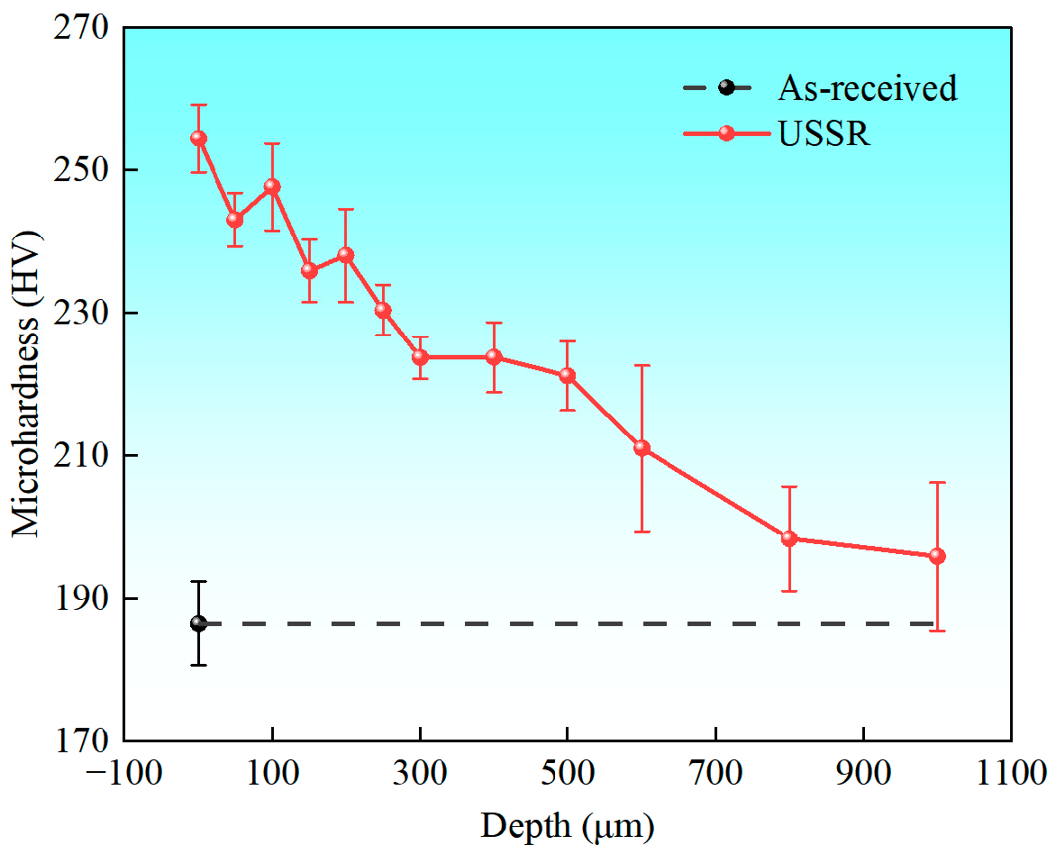
Figure 8 illustrates the microhardness variation along the depth of the USSR sample. The value at 0 μm corresponds to the surface hardness. Microhardness gradually decreases from the surface to the core, forming a distinct gradient hardness profile. The surface achieves a maximum hardness of 254.4 ± 4.8 HV, which is 1.4 times higher than that of the as-received sample. Notably, even at a depth of 1 mm, the microhardness remains slightly elevated compared to the as-received sample. This gradient distribution confirms that USSR processing generates a hardened surface layer with a thickness exceeding 1 mm.
Figure 9 presents the comparative engineering stress-strain curves of the as-received and USSR samples, while Figure 10 quantitatively summarizes their mechanical properties. The as-received material exhibits relatively low strength, with a yield strength (YS) of 251.1 ± 16.1 MPa and an ultimate tensile strength (UTS) of 409.8 ± 22.9 MPa, yet it displays exceptional ductility, achieving a total elongation of 14.6 ± 1.1%. Remarkably, USSR processing induces a substantial strengthening effect: the YS and UTS increase significantly to 582.4 ± 31.0 MPa and 775.3 ± 33.9 MPa, respectively. These values represent a 131.3% improvement in YS and an 89.5% enhancement in UTS compared to the as-received sample. Notably, despite the pronounced strength improvement, the USSR sample retains a competitive elongation of 9.3 ± 1.0%, demonstrating an optimal balance between strength and ductility. The USSR sample exhibits a superior strength-ductility synergy, outperforming both conventional and severe plastic deformed brass [6,10,11].

3.4. Wear Resistance

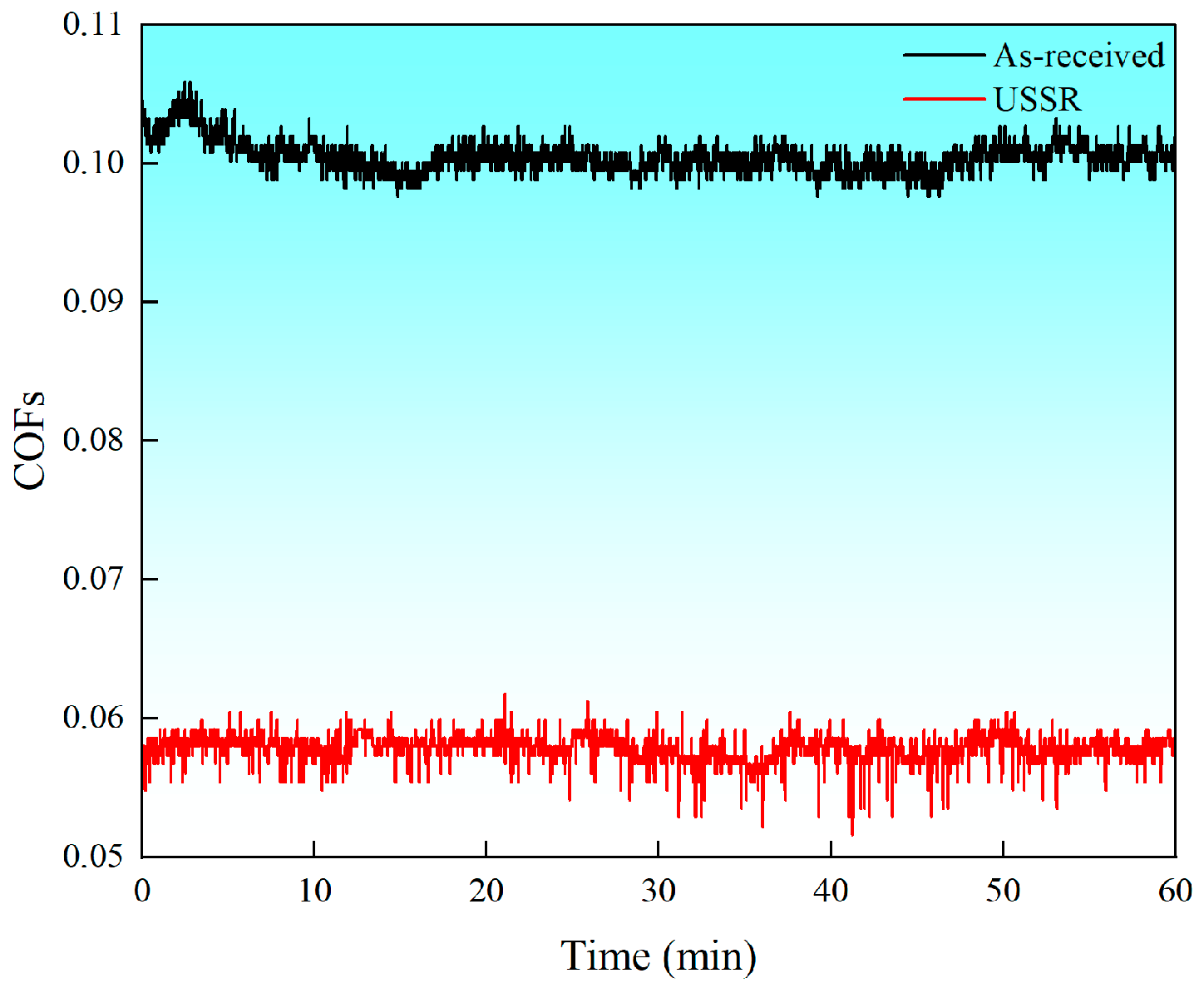
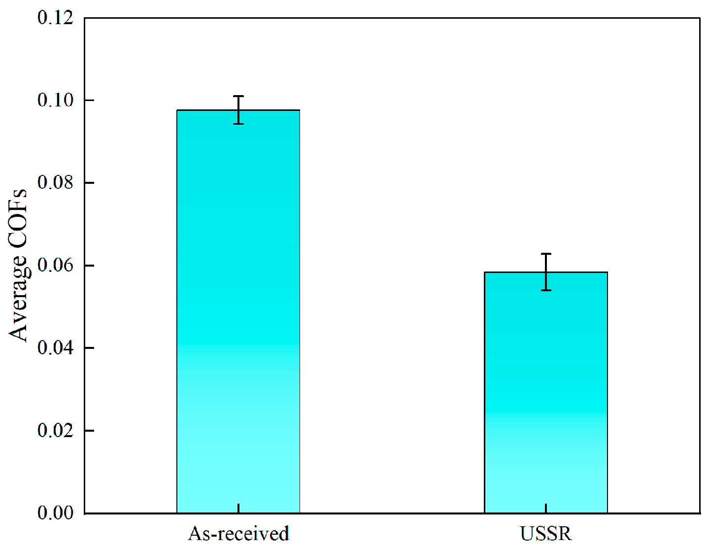
Figure 11 displays the evolution of coefficients of friction (COF) during wear tests, and Figure 12 depicts the average COFs. A statistically significant reduction in COF is observed, decreasing from 0.098 ± 0.0034 in the as-received sample to 0.058 ± 0.0044 in the USSR sample, corresponding to a 40.82% decrease. This finding confirms that the USSR process significantly lowers the COF of the brass under oil lubrication conditions.
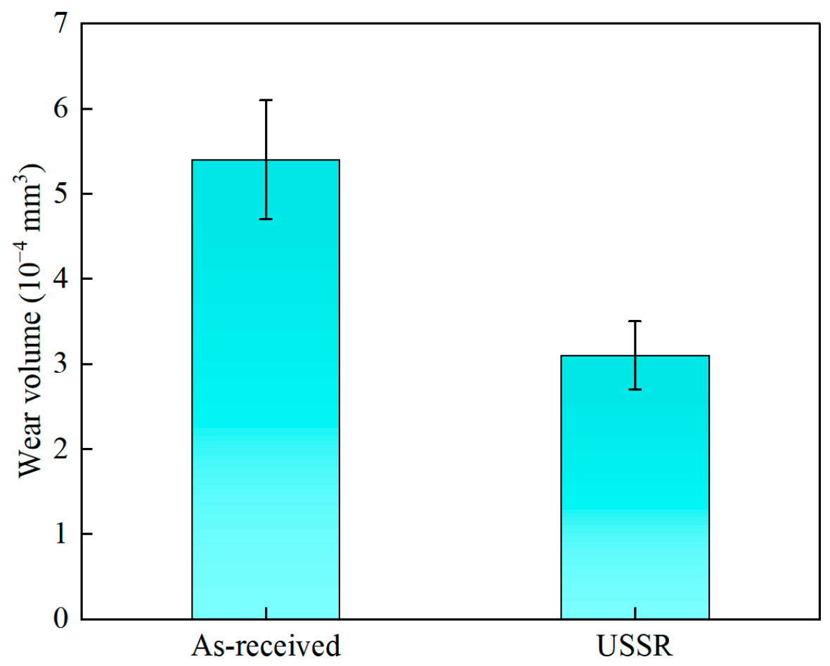
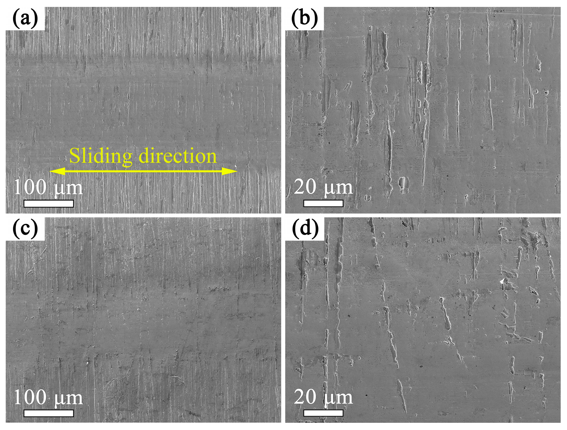
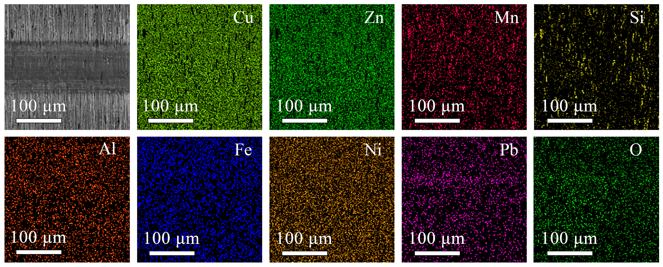
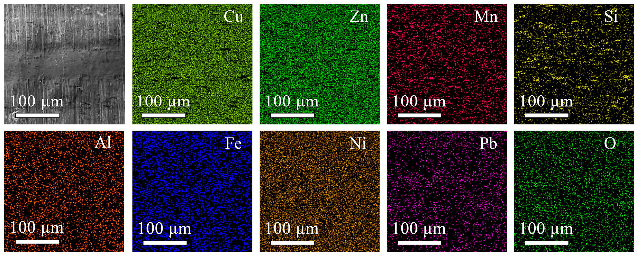
The wear test results revealed a significant reduction in wear volume from 5.4 ± 0.7 × 10⁻⁴ mm3 for the as-received sample to 3.1 ± 0.4 × 10⁻⁴ mm3 for USSR sample, corresponding to a 42.32% decrease attributable to the USSR processing, as illustrated in Figure 13. This quantitative result demonstrates the enhanced wear resistance imparted by the USSR processing on the investigated brass. Figure 14 compares the SEM images of wear scars on the as-received and USSR samples. The wear scar width of the USSR sample is dramatically reduced compared to the as-received sample, confirming the enhanced wear resistance imparted by the USSR processing. EDS elemental mapping reveals no significant oxygen enrichment within the wear scars of either sample, indicating that severe oxidative wear did not dominate the material removal process, as shown in Figure 15 and Figure 16. Furthermore, the wear scar morphology of both samples exhibits striking similarities, characterized by parallel grooves and localized plastic deformation (Figure 14). This similarity suggests that the primary wear mechanism for both investigated samples is abrasive wear, driven by the plowing action of the hard alumina counterbody.

4. Discussion

Paradoxically, the USSR sample’s asymmetric bilayer architecture demonstrates superior mechanical properties, contrasting sharply with our intuition. Yang et al. reported that the symmetric hard-soft-hard sandwich structures in gradient pure copper exhibited superior mechanical properties relative to their asymmetric counterparts, attributing to comprehensive global constraint [28]. Notably, the asymmetric Cu sample displayed markedly reduced ductility. However, our preceding investigations revealed that the gradient structured magnesium alloys maintained exceptional strength-ductility synergy despite similar asymmetric architecture [29]. Comparative analysis elucidates this discrepancy: while Cu’s gradient surface layer exhibited near-zero ductility, the Mg alloy’s gradient layer retained substantial ductility. This observation suggest that the gradient materials’ mechanical behavior is fundamentally governed by the intrinsic properties of their gradient layers.
Our microstructural characterization reveals distinctive evolution patterns in the USSR sample’s gradient dual-phase surface layer. Quantitative analysis demonstrates progressive grain coarsening (from α-phase to β’-phase) and dislocation density reduction with increasing depth. The Hall-Petch relationship dictates that yield strength σy [30]:
σ y d 1 2
where d denotes average grain size, establishing an inverse correlation between dimensional refinement and strength. Concurrently, Taylor’s strengthening model indicates [30]:
σ y ρ
where ρ represents dislocation density. Consequently, the gradient architecture generates spatially varying strength profiles corresponding to depth-dependent microstructural parameters. This theoretical prediction finds experimental validation through the measured hardness gradient (Figure 8), given the direct correlation between hardness and strength [17].
As a dual-phase alloy, the present brass exhibits heterogeneous microstructure composed of two constituent phases with different mechanical behavior. The hard phase (β’ phase) contributes to elevated strength, whereas the soft phase (α phase) imparts superior ductility. Moreover, the incompatibility between the two phases may result in hetero-deformation induced (HDI) strengthening and hardening effects for good strength-ductility balance. The present gradient dual-phase structure represents an integration of gradient nanostructure and dual-phase structure, thereby generating enhanced microstructural heterogeneity that induces pronounced HDI strengthening and hardening effects [31]. Previous studies have proven that this HDI strengthening mechanism enables heterostructured materials to transcend the strength predictions of the mixture rule, thereby establishing it as a fundamental strength origin in heterostructured materials [32]. The HDI hardening effect enhances strain hardening capacity while suppressing premature strain localization, thereby synergistically improving the ductility.
Our experimental finding demonstrates that abrasive wear constitutes the predominant wear mechanism for both the as-received and USSR sample under hydraulic oil lubrication condition. The USSR sample exhibits elevated surface hardness and strength, which enhances their resistance to plastic deformation and microabrasive scratching. As shown in Figure 14, the wear scar on the USSR sample exhibits a smoother morphology compared to the as-received counterpart, confirming its enhanced resistance to plastic deformation during the wear process. Therefore, this improved mechanical properties directly correlates with the observed enhancement in wear resistance and the reduction in the coefficient of friction (COF).

5. Conclusions

(1)
A gradient dual-phase structured surface layer is prepared in the brass through USSR processing. Detailed microstructure characterization demonstrates this structure is featured by progressive grain coarsening for both α phase to β’ phase and dislocation density reduction with increasing depth.
(2)
The USSR sample exhibits exceptional mechanical properties with a high yield strength of 582.4 ± 31.0 MPa and ultimate tensile strength of 775.3 ± 33.9 MPa, while maintaining competitive ductility of 9.3 ± 1.0%. This yield strength is 2.3 times as high as its as-received counterpart.
(3)
Quantitative sliding wear under oil lubrication condition demonstrates a 42.32% reduction in wear volume and 40.82% decrease in COF the USSR sample relative to its as-received counterpart, while maintaining identical dominant wear mechanisms, i.e., abrasive wear.

Author Contributions

Conceptualization, J.H. and J.Z. (Jiyun Zhao); Methodology, T.Z. and J.Z. (Jing Zhang); investigation, T.Z. and J.Z. (Jing Zhang); Data curation, T.Z.; Writing—original draft preparation, J.H. and T.Z.; Writing—review and editing, J.H., B.Z. and J.Z. (Jiyun Zhao); Visualization, T.Z.; Supervision, J.H. and J.Z. (Jiyun Zhao); Project administration, J.H.; Funding acquisition, J.H. and B.Z. All authors have read and agreed to the published version of the manuscript.

Funding

This research was funded by National Key Research and Development Program of China, grant number 2023YFB34066702, 2023YFB34066700.

Data Availability Statement

The raw data supporting the conclusions of this article will be made available by the authors on request.

Acknowledgments

We appreciate Haiyong Shi, Xingyue Zhang, Chao Cao, Di Huang for Writing—review and editing.

Conflicts of Interest

The authors declare no conflicts of interest.

References

  1. Xu, B.; Sun, J.; Han, J.; Yang, Z.; Zhou, H.; Xiao, L.; Xu, S.; Han, Y.; Ma, A.; Wu, G. Effect of hierarchical precipitates on corrosion behavior of fine-grain magnesium-gadolinium-silver alloy. Corros. Sci. 2022, 194, 109924. [Google Scholar] [CrossRef]
  2. Xu, B.; Sun, J.; Yang, Z.; Xiao, L.; Zhou, H.; Han, J.; Liu, H.; Wu, Y.; Yuan, Y.; Zhuo, X.; et al. Microstructure and anisotropic mechanical behavior of the high-strength and ductility AZ91 Mg alloy processed by hot extrusion and multi-pass RD-ECAP. Mater. Sci. Eng. A 2020, 780, 139191. [Google Scholar] [CrossRef]
  3. Bahmanpour, H.; Youssef, K.M.; Horky, J.; Setman, D.; Atwater, M.A.; Zehetbauer, M.J.; Scattergood, R.O.; Koch, C.C. Deformation twins and related softening behavior in nanocrystalline Cu–30% Zn alloy. Acta Mater. 2012, 60, 3340–3349. [Google Scholar] [CrossRef]
  4. Zhang, Y.; He, C.; Yu, Q.; Li, X.; Wang, X.; Zhang, Y.; Wang, J.; Jiang, C.; Jia, Y.; Zhang, X.-C.; et al. Nacre-like surface nanolaminates enhance fatigue resistance of pure titanium. Nat. Commun. 2024, 15, 6917. [Google Scholar] [CrossRef] [PubMed]
  5. Fang, T.H.; Li, W.L.; Tao, N.R.; Lu, K. Revealing extraordinary intrinsic tensile plasticity in gradient nano-grained Copper. Science 2011, 331, 1587–1590. [Google Scholar] [CrossRef]
  6. Zhang, P.; An, X.H.; Zhang, Z.J.; Wu, S.D.; Li, S.X.; Zhang, Z.F.; Figueiredo, R.B.; Gao, N.; Langdon, T.G. Optimizing strength and ductility of Cu–Zn alloys through severe plastic deformation. Scr. Mater. 2012, 67, 871–874. [Google Scholar] [CrossRef]
  7. Sun, J.; Fang, L.; Sun, K.; Han, J. Direct observation of dislocations originating from perfect twin boundaries. Scr. Mater. 2011, 65, 501–504. [Google Scholar] [CrossRef]
  8. Sun, J.; Yang, Z.; Han, J.; Liu, H.; Song, D.; Jiang, J.; Ma, A. High strength and ductility AZ91 magnesium alloy with multi-heterogenous microstructures prepared by high-temperature ECAP and short-time aging. Mater. Sci. Eng. A 2018, 734, 485–490. [Google Scholar] [CrossRef]
  9. Zhu, Y.; Wu, X. Heterostructured materials. Prog. Mater. Sci. 2023, 131, 557. [Google Scholar] [CrossRef]
  10. Gu, L.; Liang, N.; Chen, Y.; Zhao, Y. Achieving maximum strength-ductility combination in fine-grained Cu-Zn alloy via detwinning and twinning deformation mechanisms. J. Alloy. Compd. 2022, 906, 164401. [Google Scholar] [CrossRef]
  11. Chen, J.; Su, Y.; Zhang, Q.; Sun, J.; Yang, D.; Jiang, J.; Song, D.; Ma, A. Enhancement of strength-ductility synergy in ultrafine-grained Cu-Zn alloy prepared by ECAP and subsequent annealing. J. Mater. Res. Technol. 2022, 17, 433–440. [Google Scholar] [CrossRef]
  12. Ji, W.; Zhou, R.; Vivegananthan, P.; Wu, M.S.; Gao, H.; Zhou, K. Recent progress in gradient-structured metals and alloys. Prog. Mater. Sci. 2023, 140, 101194. [Google Scholar] [CrossRef]
  13. Han, J.; Zhang, Y.; Zhang, Z.; Cao, C.; Huang, D.; Sun, J.; Zhao, J. Unveiling the deformation mechanism of high-strength low-alloy structural steel with gradient dislocation-cell structure. Chin. J. Mech. Eng. 2025, 38, 35. [Google Scholar] [CrossRef]
  14. Guo, J.; He, Q.Y.; Mei, Q.S.; Huang, X.; Wu, G.L.; Mishin, O.V. Gradient microstructure, recrystallization and mechanical properties of copper processed by high pressure surface rolling. J. Mater. Sci. Technol. 2022, 126, 182–190. [Google Scholar] [CrossRef]
  15. Deng, S.Q.; Godfrey, A.; Liu, W.; Hansen, N. A gradient nanostructure generated in pure copper by platen friction sliding deformation. Scr. Mater. 2016, 117, 41–45. [Google Scholar] [CrossRef]
  16. Lu, J.Z.; Duan, H.F.; Luo, K.Y.; Wu, L.J.; Deng, W.W.; Cai, J. Tensile properties and surface nanocrystallization analyses of H62 brass subjected to room-temperature and warm laser shock peening. J. Alloys Compd. 2017, 698, 633–642. [Google Scholar] [CrossRef]
  17. Wang, Y.F.; Huang, C.X.; Wang, M.S.; Li, Y.S.; Zhu, Y.T. Quantifying the synergetic strengthening in gradient material. Scr. Mater. 2018, 150, 22–25. [Google Scholar] [CrossRef]
  18. Chen, X.; Han, Z.; Li, X.Y.; Lu, K. Lowering coefficient of friction in Cu alloys with stable gradient nanostructures. Sci. Adv. 2016, 2, e1601942. [Google Scholar] [CrossRef]
  19. Chen, X.; Han, Z. A low-to-high friction transition in gradient nano-grained Cu and Cu-Ag alloys. Friction 2021, 9, 1558–1567. [Google Scholar] [CrossRef]
  20. Chen, X.; Han, Z.; Lu, K. Enhancing wear resistance of Cu–Al alloy by controlling subsurface dynamic recrystallization. Scr. Mater. 2015, 101, 76–79. [Google Scholar] [CrossRef]
  21. Liu, Y.; Sun, J.; Fu, Y.; Xu, B.; Li, B.; Xu, S.; Huang, P.; Cheng, J.; Han, Y.; Han, J.; et al. Tuning strength-ductility combination on selective laser melted 316L stainless steel through gradient heterogeneous structure. Addit. Manuf. 2021, 48, 102373. [Google Scholar] [CrossRef]
  22. Han, J.; Sun, J.; Song, Y.; Xu, B.; Yang, Z.; Xu, S.; Han, Y.; Wu, G.; Zhao, J. Achieving gradient heterogeneous structure in Mg alloy for excellent strength-ductility synergy. J. Magnes. Alloy. 2023, 11, 2392–2403. [Google Scholar] [CrossRef]
  23. Li, X.; Lu, L.; Li, J.; Zhang, X.; Gao, H. Mechanical properties and deformation mechanisms of gradient nanostructured metals and alloys. Nat. Rev. Mater. 2020, 5, 706–723. [Google Scholar] [CrossRef]
  24. Sun, Q.; Sun, J.; Fu, Y.; Xu, B.; Han, Y.; Chen, J.; Han, J.; Wu, H.; Wu, G. Preparing thick gradient surface layer in Cu-Zn alloy via ultrasonic severe surface rolling for strength-ductility balance. Materials 2022, 15, 7687. [Google Scholar] [CrossRef] [PubMed]
  25. ASTM G 133-05; Standard Test Method for Linearly Reciprocating Ball-on-Flat Sliding Wear. ASTM International: West Conshohocken, PA, USA, 2016.
  26. Pugacheva, N.B. Structure of commercial α + β brasses. Metal Sci. Heat Treat. 2007, 49, 67–74. [Google Scholar] [CrossRef]
  27. Mousavi, S.E.; Sonboli, A.; Naghshehkesh, N.; Meratian, M.; Salehi, A.; Sanayei, M. Different behavior of alpha and beta phases in a low stacking fault energy copper alloy under severe plastic deformation. Mater. Sci. Eng. A 2020, 788, 139550. [Google Scholar] [CrossRef]
  28. Yang, J.; Xu, L.; Gao, H.; Li, X.; Pan, H.; Shu, B.; Itoh, T.; Zhu, Y.; Zhu, X. Effect of global constraint on the mechanical behavior of gradient materials. Mater. Sci. Eng. A 2021, 826, 141963. [Google Scholar] [CrossRef]
  29. Xu, B.; Sun, J.; Wang, L.; Han, J.; Wu, G. Balanced strength and ductility by asymmetric gradient nanostructure in AZ91 Mg alloy. J. Mater. Sci. Technol. 2024, 184, 167–179. [Google Scholar] [CrossRef]
  30. Luo, P.; McDonald, D.; Xu, W.; Palanisamy, S.; Dargusch, M.; Xia, K. A modified Hall–Petch relationship in ultrafine-grained titanium recycled from chips by equal channel angular pressing. Scr. Mater. 2012, 66, 785–788. [Google Scholar] [CrossRef]
  31. Xu, S.; Han, Y.; Sun, J.; Zu, G.; Jiang, M.; Zhu, W.; Ran, X. Designing gradient nanograined dual-phase structure in duplex stainless steel for superior strength-ductility synergy. J. Mater. Sci. Technol. 2024, 170, 122–128. [Google Scholar] [CrossRef]
  32. Zhu, Y.; Ameyama, K.; Anderson, P.M.; Beyerlein, I.J.; Gao, H.; Kim, H.S.; Lavernia, E.; Mathaudhu, S.; Mughrabi, H.; Ritchie, R.O.; et al. Heterostructured materials: Superior properties from hetero-zone interaction. Mater. Res. Lett. 2021, 9, 1–31. [Google Scholar] [CrossRef]
Figure 1. Schematic diagram of the USSR processing.
Metals 15 00515 g001
Figure 2. SEM result of the as-received sample: (a) SEM image and (b) corresponding EDS element mappings.
Metals 15 00515 g002
Figure 3. XRD patter of the as-received sample.
Metals 15 00515 g003
Figure 4. EBSD result of the as-received sample: (a) IPF mapping, (b) phase distribution mapping, and (c) KAM mapping.
Metals 15 00515 g004
Figure 5. EBSD result of the USSR sample: (a) IPF mapping, (b) phase mapping and (c) KAM mapping.
Metals 15 00515 g005
Figure 6. GND density variation along depth of the USSR sample. The GND density of the as-received is also shown.
Metals 15 00515 g006
Figure 7. SEM result of the USSR sample: (a) SEM image and (b) corresponding EDS element mappings.
Metals 15 00515 g007
Figure 8. Hardness variation along depth of the USSR sample. The hardness of the as-received sample is also shown.
Metals 15 00515 g008
Figure 9. Engineering stress-strain curves of the as-received and USSR samples.
Metals 15 00515 g009
Figure 10. Mechanical properties of the as-received and USSR samples.
Metals 15 00515 g010
Figure 11. Variation of COFs with sliding time of the as-received and USSR samples.
Metals 15 00515 g011
Figure 12. Average COFs of the as-received and USSR samples.
Metals 15 00515 g012
Figure 13. Wear volume of the as-received and USSR samples.
Metals 15 00515 g013
Figure 14. SEM image of the wear scars of (a,b) the as-received sample and (c,d) USSR sample.
Metals 15 00515 g014
Figure 15. EDS element mappings of the as-received sample after wear.
Metals 15 00515 g015
Figure 16. EDS element mappings of the USSR sample after wear.
Metals 15 00515 g016
Table 1. Chemical composition of the investigated brass.
Element.CuZnMnSiAlPbNiFeSn
Content (wt%)62.7234.482.481.551.130.360.150.090.07
Disclaimer/Publisher’s Note: The statements, opinions and data contained in all publications are solely those of the individual author(s) and contributor(s) and not of MDPI and/or the editor(s). MDPI and/or the editor(s) disclaim responsibility for any injury to people or property resulting from any ideas, methods, instructions or products referred to in the content.