Article

Failure Analysis and Corrosion Resistance of Carbon Steel Pipelines in Concentrated Sulfuric Acid

Electrochemistry and Corrosion Laboratory, School of Mechanical Engineering and Rail Transit, Changzhou University, Changzhou 213164, China
*
Author to whom correspondence should be addressed.
Metals 2025, 15(5), 506; https://doi.org/10.3390/met15050506
Submission received: 27 March 2025 / Revised: 27 April 2025 / Accepted: 28 April 2025 / Published: 30 April 2025

Abstract

:
This study examines the waste sulfuric acid pipeline within the waste acid system from a certain petrochemical company, specifically, related to its sulfuric acid alkylation process. The current study sought to investigate the corrosion perforation mechanism of pipelines and revealed the synergistic effects of sulfuric acid temperature and concentration on the corrosion behavior of 20# carbon steel. The corrosion features of the failed part were analyzed by scanning electron microscopy, X-ray energy-dispersive spectroscopy, and X-ray diffraction. The corrosion rates of 20# carbon steel in sulfuric acid at different concentrations (80%, 90%, 98%) and working temperatures (20 °C, 40 °C) were measured using the immersion corrosion method, potentiodynamic polarization curves, and electrochemical impedance spectroscopy. The results indicate that the failed pipeline exhibited multi-form corrosion characteristics, with both uniform and localized corrosion occurring simultaneously in concentrated sulfuric acid. The lowest corrosion rate was 0.0795 mm/a in 98% H2SO4 at 40 °C. The sulfuric acid concentration and working temperature exhibited synergistic effects on the corrosion behavior of 20# carbon steel. The corrosion rates increased with concentration in the range of 80–90% H2SO4 but reached a minimum of 98% due to passive film formation. In a nutshell, we established that elevated temperatures accelerated corrosion in low-concentration systems, but triggered localized active dissolution in high-concentration systems by disrupting the passive film on the surface of the steel.

1. Introduction

Recently, safety issues caused by corrosion failures in petrochemical equipment such as heat exchangers and pressure pipelines have become increasingly prominent, seriously restricting the survival and long-term stable operation of enterprises [1,2]. Corrosion problems in sulfuric acid alkylation units have always existed, with the most common issues including corrosion-induced leakage in acid pipelines [3]. Therefore, clarifying the corrosion-induced leakage and corrosion perforation mechanisms in waste acid pipelines holds significant importance for enhancing the safety of pipelines.
Sulfuric acid is a strongly corrosive medium and erodes metal interfaces by altering their surface states [4,5]. Typical applications of carbon steels or cast irons include the storage of 92–98 wt.% sulfuric acid in tanks at temperatures below 50 °C or storage of 78–90 wt.% sulfuric acid at temperatures below 25 °C, and the construction of pumps and large-sized pipelines handling acid at low flow rates. Stainless steels are mainly used in components exposed to hot concentrated sulfuric acid because stable protective passive films are formed. Extensive studies have demonstrated that alloy composition significantly influences corrosion behavior in sulfuric acid environments. For carbon steels, corrosion resistance is primarily governed by the properties of FeSO4 corrosion products [6,7], whereas austenitic stainless steels rely on the formation of iron- and chromium-rich oxide films [8,9]. Recent research further highlights the role of specific alloying elements and protective coatings [10,11,12,13,14,15,16,17]. Li et al. [10] investigated the corrosion behaviors of FeCoCrNiMn-(N,Si) and FeCoCrNiMn high-entropy alloys (HEAs) in 0.5 M H2SO4 aqueous solution. Their results indicated that FeCoCrNiMn-(N,Si) showed superior corrosion resistance to FeCoCrNiMn, which can be ascribed to the enrichment of N and Si in the form of NH4+ and SiO2 on the surface of the passive film, as well as the presence of Cr2O3. Fujimura et al. [12] discussed the passivation effect of Al and Si during the corrosion process, and indicated that the addition of Al and Si in Fe-Cr alloys could effectively improve the corrosion resistance of stainless steel. In addition, Cabral-Miramontes et al. [13] analyzed the influence of anodizing parameters on aluminum–copper alloy (AA 2024) using a bath of citric–sulfuric acid with different anodizing current densities on the thickness, microhardness, and corrosion resistance of the anodized layer. The results showed that corrosion resistance anodizing in citric–sulfuric acid solutions with a current density of 0.06 A/cm2 was the best with a corrosion current density (jcorr) of 1.29 × 10⁻⁸ A/cm2. Trentin et al. [14] investigated the pitting behavior of seven stainless steel grades with austenitic and duplex microstructures in varying acids (HCl, H2SO4, HCOOH), chloride concentrations (500–5000 mg/L), and pH values (2.5, 4.0). Conclusions showed that low- and intermediate-PREN grades were prone to pitting under the test conditions. The electrolyte ranking by pitting susceptibility was HCl > H2SO4 > HCOOH, while the progress of pitting attack followed the reverse order: HCOOH > H2SO4 > HCl. Hayashida et al. [15] evaluated the corrosion resistance of carbon steel covered with a resin coating containing nickel sulfate under a chloride and sulfuric acid mist environment. It was found that nickel sulfate promoted the formation of goethite and akaganeite. Moreover, Gola et al. [16] investigated the effect of the microstructure of Inconel 625 additively manufactured by laser powder bed fusion (LPBF) and laser-assisted directed energy deposition (LDED) on the resistance to corrosion in sulfuric acid solution. It was determined that a higher drop in impedance and increase in corrosion current occurred in LPBF than LDED Inconel 625, which was mainly related to a more intensive propagation of corrosion pits in areas with higher free energy. Also, Chowdhury et al. [17] investigated the corrosion resistance of a metallic coating deposited on AISI 1080 low carbon steel. Their results showed that the corrosion under static conditions was higher than that of dynamic conditions both for coated and uncoated surfaces. Nickel-plated steel exhibits more corrosion resistance in H2SO4 corrosive mediums when compared with chrome-plated steel. On the other hand, chrome plating on steel provides more corrosion resistance compared to galvanized steel.
In addition, corrosion behavior is also modulated by environmental parameters such as temperature, acid concentration, and fluid dynamics. Javidi et al. [18] further explored synergistic interactions between temperature, sulfuric acid concentration, and flow velocity on austenitic SS 304L/316L and found that these parameters synergistically affect the corrosion behavior and passive film properties of the surface. Surface passive films formed at high concentrations are less defective and increasing temperature and solution flow introduced more defects. However, the passive film repaired itself. Increasing the temperature and solution flow resulted in higher passive film coverage and cracking of the passive film, respectively. Ouarga et al. [19] provided a comprehensive overview of alloy selection criteria under varying H2SO4 concentrations, temperatures, and harsh conditions (e.g., erosion–corrosion, contaminants), emphasizing the need for tailored material solutions. Huttunen-Saarivirta et al. [20] investigated the corrosion behavior of three stainless steel grades at two H2SO4 concentrations, namely 1 wt.% and 10 wt.%, with varying NaCl concentrations in the range from 500 mg/L to 10,000 mg/L. The chloride-to-sulfate activity ratio, ⁠a(Cl)/a(SO42−), was found to be the key parameter in defining the occurrence of pitting corrosion for all three alloys. In H2SO4-NaCl systems, no pitting occurred at the activity ratio below 10, with higher values inducing pitting attack, particularly in 1 wt.% H2SO4. Abdelfatah et al. [21] investigated the corrosion behavior of austenitic stainless steel 304 (SS) in various concentrations of H2SO4 and NaCl solutions. Results showed that the corrosion rate of 304 SS decreases with increasing NaCl concentrations. On the other hand, the corrosion rate increased with increasing H2SO4 concentrations.
Also, the semiconductor properties and electrochemical response of passive films have been extensively investigated. Fattah-Alhosseini et al. [22] analyzed the capacitance behaviors of 316L passive films across H2SO4 concentrations, noting comparable passivation performance despite varying solution strengths. Advanced electrochemical techniques have enabled mechanistic insights, including electrochemical impedance spectroscopy (EIS) and potentiodynamic polarization. Boissy et al. [23] developed a specific equivalent circuit to investigate transport phenomena within the passive film of 316L steel, proposing the vacancy diffusion coefficient in the passive film. Tang et al. [24] studied the corrosion mechanism of palladium-coated stainless steel membranes in boiling sulfuric acid solutions and established a corrosion protection method. Huang et al. [25] demonstrated superior corrosion resistance of high-entropy alloy films over 316L in 0.5 M H2SO4, with corrosion current densities an order of magnitude lower.
In addition, to mitigate the corrosive impact of steel, protective strategies typically involve adding corrosion inhibitors to form a protective barrier on the steel surface and reduce the interaction of corrosion. Tao et al. [26] studied 1-Phenyl-1H-tetrazol (PHT), an efficient corrosion inhibitor for X65 steel in the sulfuric acid corrosion environment. Results showed that as the PHT concentration increased, the value of the corrosion current density decreased significantly. When the PHT concentration was 1 mM, the corrosion inhibition efficiency could reach 92.1%. Furthermore, Chen et al. [27] explored the effect of two corrosion inhibitors on carbon steel in 1 mol/L sulfuric acid. The results indicated that both inhibitors had good corrosion resistance to 1.0 mol/L sulfuric acid at 30 °C. In addition, Gapsari et al. [28] investigated the potential of andrographis paniculata leaf extract (APLE) as a sustainable, green corrosion inhibitor for mild steel in concentrated sulfuric acid, which had a high inhibition efficiency of 95.14% at a concentration of 4000 ppm, effectively reducing both anodic and cathodic corrosion reactions.
Despite these advances, systematic studies on the synergistic effects of sulfuric acid concentration and temperature on carbon steel, particularly in industrial waste acid scenarios, remain limited. Most prior works focus on stainless steels or alloys in controlled laboratory conditions, leaving a gap in understanding the dissolution of carbon steel under realistic alkylation process conditions. This study is based on the engineering background, combined with the material failure analysis under actual working conditions and multi-scale experimental verification, aiming to elucidate the synergistic corrosion mechanisms of 20# carbon steel in sulfuric acid and provide theoretical support for waste acid management in alkylation processes.

2. Corrosion Failure Analysis
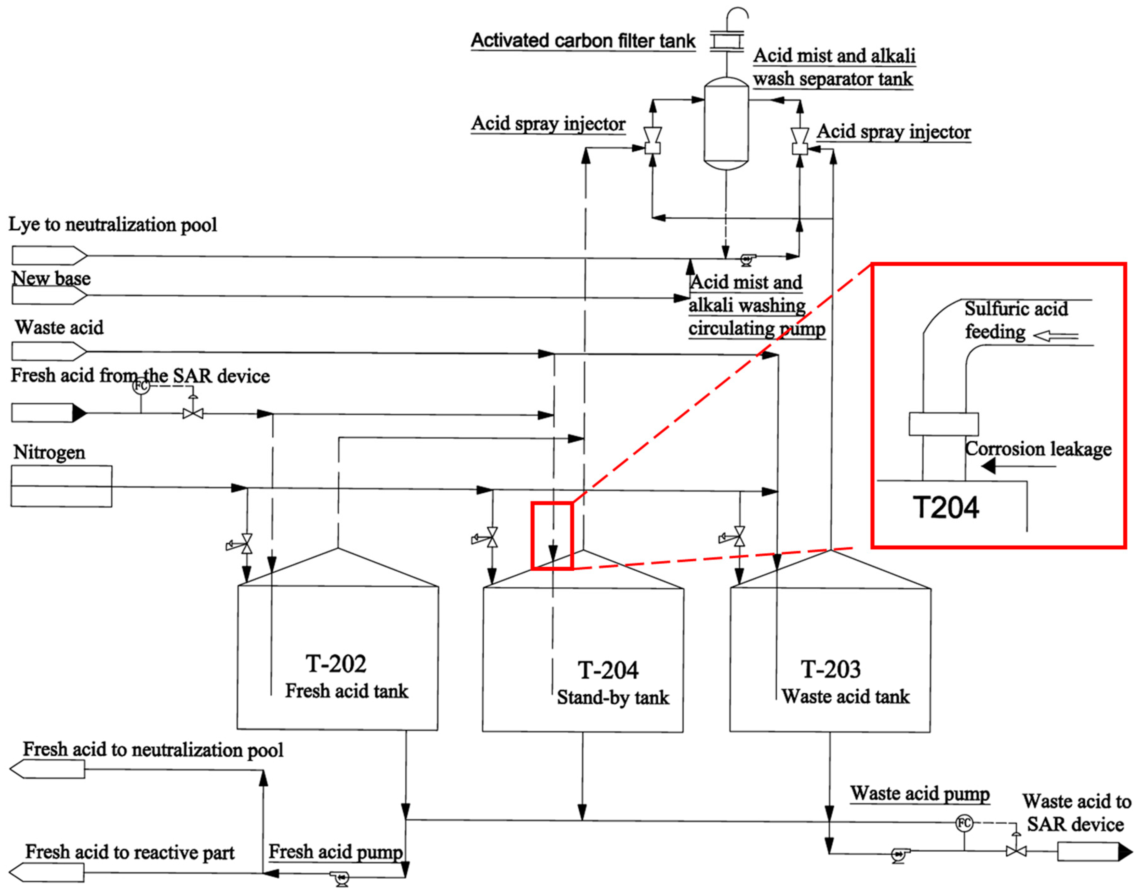
2.1. Process Flow

The alkylation unit combines low-molecular-weight olefins with isobutane under the action of a catalyst to produce alkylate oil. The alkylation process using sulfuric acid as a catalyst mainly consists of raw material pretreatment, alkylation reaction, flash evaporation and compression refrigeration, reaction refining, reaction product fractionation, and chemical treatment. Herein, the waste acid pipeline is based on the chemical treatment part of the sulfuric acid alkylation process. The process flow diagram of the acid storage tank section of the alkylation unit in a certain petrochemical enterprise is shown in Figure 1. From left to right, there are three tanks, T-202, T-204, and T-203. The waste acid from the D-217 tank flows into both the T-204 and T-203 tanks, and the fresh acid from the SAR unit is fed into both the T-202 and T-204 tanks. The waste acid produced by T-202 is also fed into the T-204 tank. The acid tank is operated under micro-positive pressure. The acid mist discharged from the top of the tank is mixed with the circulating lye in the acid mist ejector EJ-202 to neutralize the SO2 in it, and then enters the acid storage tank acid mist washing deliquidization tank D-220 to separate the lye in the remaining gas phase. All SO2 in contact with the circulating lye reacts with NaOH to form sodium sulfite, and continues to remain in the lye. The remaining gas phase is dehydrated from the acid storage tank, acid mist washing, deliquidization tank D-220, and top deactivated carbon adsorption tank SR-201A/B. The activated carbon in the adsorption tank SR-201A/B absorbs the hydrocarbons in the material, and the clean gas produced is vented into the atmosphere. The entire process is protected by nitrogen gas throughout. However, the failed carbon steel pipeline tube is shown in the inset of Figure 1, featured by the red line.

2.2. Analysis of Failed Components

Tank T-204 was used in 2019. In September 2021, an abnormal leakage was found in the sulfuric acid pipeline of the T-204 tank. Subsequently, the feed line of the T-204 tank was cut off from the unit, and it was discovered that the feed line of the tank body was corroded and perforated. The feed line of the T-204 tank was designed as DN100 with a wall thickness of 6.5 mm. The eddy current testing revealed that the wall thickness on one side of the corrosion perforation area thinned to 2.9 mm, while on the other side, the wall thickness in most areas thinned to 4.9–5.5 mm. The failed pipeline was located on the sulfuric acid pipeline of the acid storage tank T-204 in the chemical treatment section of the sulfuric acid alkylation unit. To further scientifically analyze the pipeline, a corrosion failure analysis of the pipeline was conducted.
The waste acid pipeline was made of 20# carbon steel, and the working environment was at 40 °C. The chemical composition (wt.%) of the steel is shown in Table 1. Therefore, 20# steel was used in the immersion corrosion and electrochemical corrosion experiments. The size of the immersed sample was set as 20 × 50 × 2 mm, whereas the size of the sample for the electrochemical test was set as 5 × 10 × 2 mm. The electrochemical sample was connected using an insulated copper wire wrapped in an epoxy resin that is resistant to high-temperature sulfuric acid corrosion. The surface of all samples was polished with sandpaper with grits from 80# to 2000#, and then rinsed with deionized water and absolute ethanol, followed by drying. Different concentrations of sulfuric acid were chosen for the test solution, which consisted of H2SO4 solution with three gradient concentrations of 80%, 90%, and 98%.

2.3. Immersion Testing Method

Prior to the immersion corrosion, each sample was weighed using an analytical balance (accuracy 0.1 mg). Each experiment was tested three times to ensure reproducibility, corresponding to three parallel samples. The samples were placed in the reagent and the test temperature was kept at 40 °C, maintaining a full immersion state for 14 days. After the test, the samples were preliminarily rinsed with deionized water, and the corrosion morphology of the samples was observed by optical microscope. The corrosion products were removed by chemical cleaning, rinsed with deionized water and absolute ethanol, dehydrated and dried, weighed again, and the corrosion rate was calculated according to Equation (1) [29].
v = 87600 m ρ A t
where Δm is the mass loss of the sample (g); ρ is the density of the sample (g/cm3); A is the area of the sample (cm2); and t is the soaking time (h).

2.4. Electrochemical Testing Method

The test instrument adopted is the 660E electrochemical workstation (Shanghai Chenhua Instrument Co., Ltd., Shanghai, China). A three-electrode system was used. The sample acted as the working electrode. The reference electrode used was the saturated calomel electrode (SCE), and the counter electrode was the platinum sheet electrode. The volume of solution in the electrolytic cell was 200 mL. Prior to Tafel polarization and EIS tests, the sample was immersed in solution for 30 min to ensure a relatively stable OCP value. Afterward, the open-circuit potential was stabilized and Tafel and EIS tests were performed. Consequently, the scanning range of the potentiodynamic polarization curve was set as ±0.4 V vs. OCP, the sweep rate was 5 mV/s, the frequency of the AC impedance spectrum was from 0.01 Hz to 100 kHz, and the perturbation potential was 10 mV. The obtained results were analyzed in the ZView Software (Version 2.7), and the results were only accepted after Chi-square for the fit was in order of 10−3.

2.5. Characterization

The samples (dimensions: 15 mm × 15 mm × 3 mm) were cut by an NC wire with the EDM machinery. The morphology, chemical composition, and phase of corrosion products was observed by a scanning electronic microscope (Sigma 500, ZEISS, Oberkochen, DE, Germany) equipped with an energy dispersive spectrometer (EDS) and X-Ray Diffraction (XRD). The chemical composition of the deposit was detected and averaged by three points.

3. Results

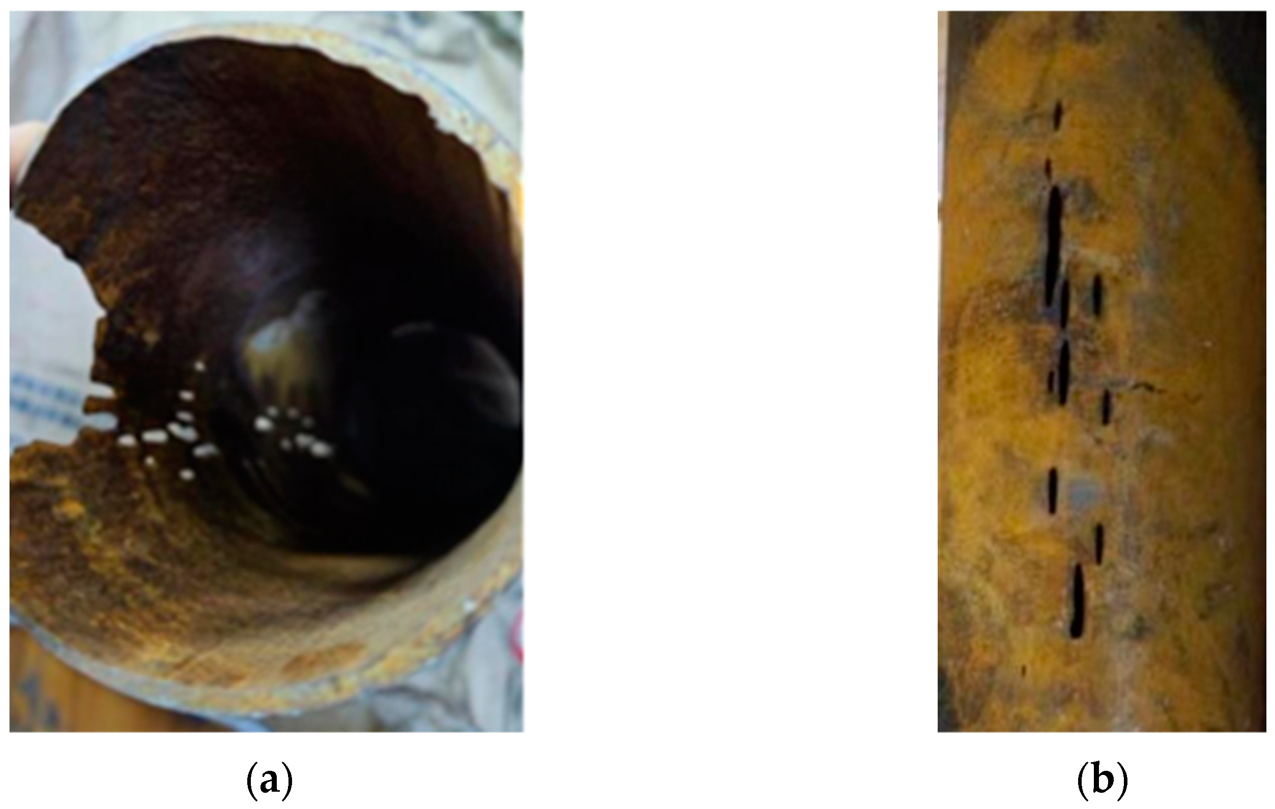
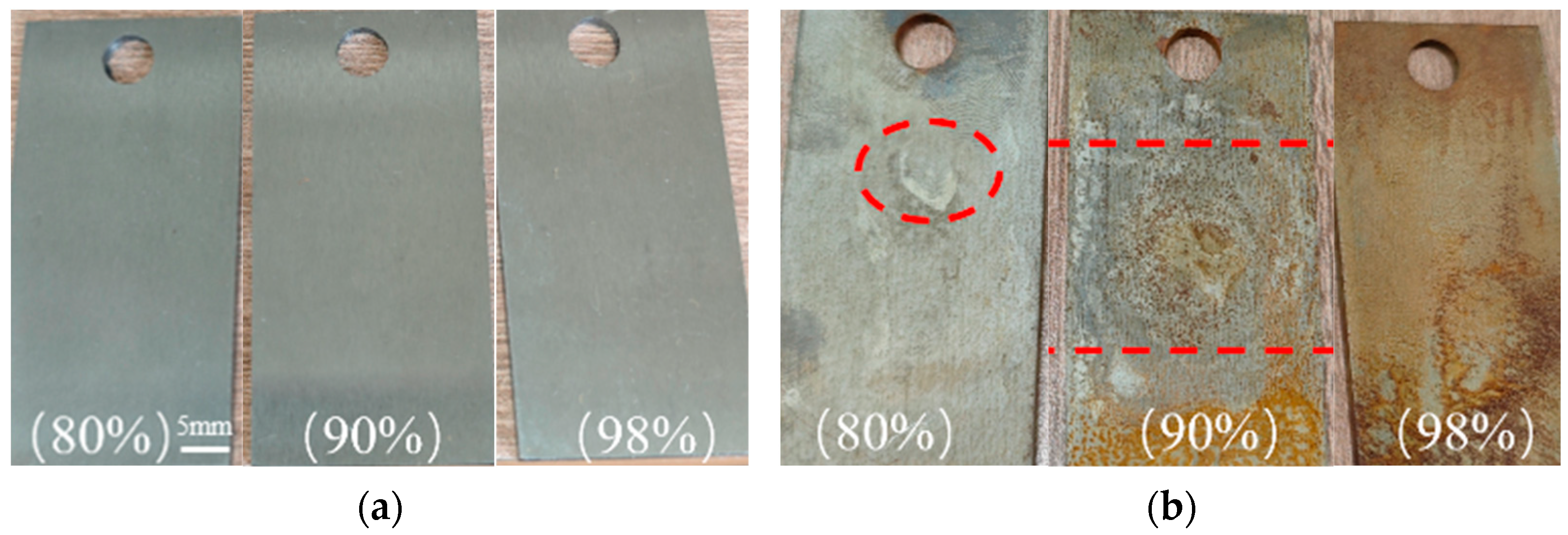
3.1. Macroscopic Morphology Analysis

The failed pipeline of the sulfuric acid alkylation unit was mechanically cut, and the macroscopic morphology of the leakage part is shown in Figure 2. According to the visual observation, the inner and outer surfaces of the pipeline are widely covered with yellow-brown or black corrosion products, and the corrosion mainly occurs on the inner surface of the pipeline (Figure 2a,b). The corrosion products are relatively dense and not easy to scrape off. Cracks in the wall of the pipeline and strip perforations of various sizes are seen clearly with the naked eye. Also, traces of corrosion are visible, mainly in the form of circular pits and grooves. As the trench corrosion pits gradually deepened, the pipeline corrosion leakage and perforation are triggered, and the wall thickness is significantly reduced.

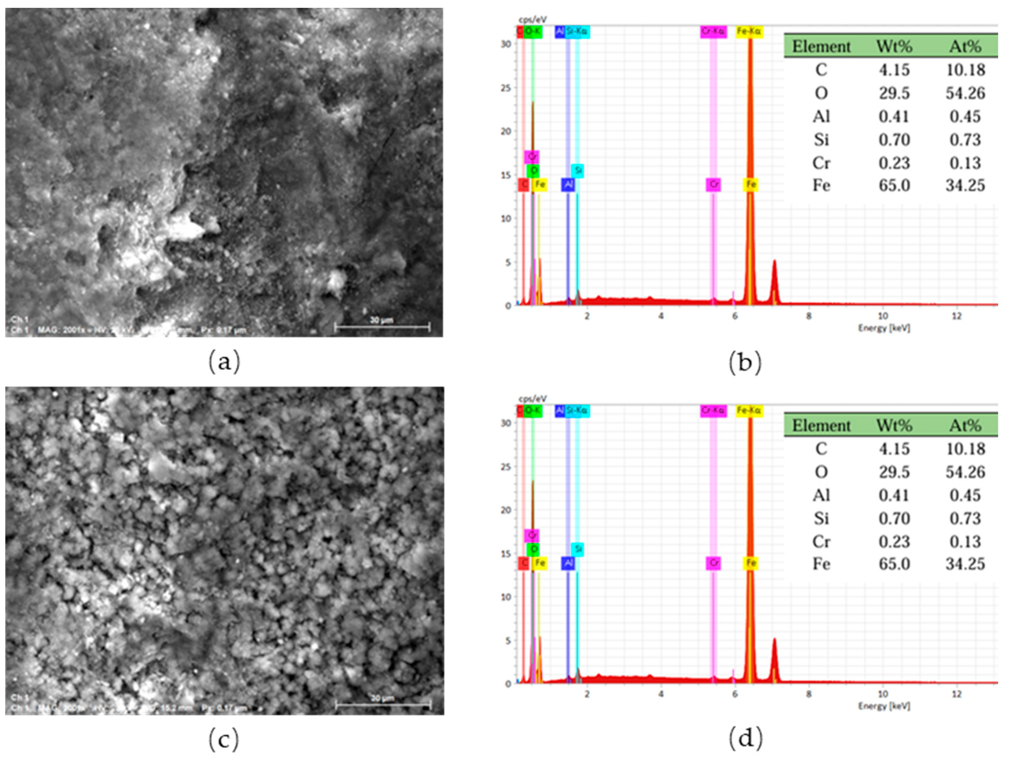
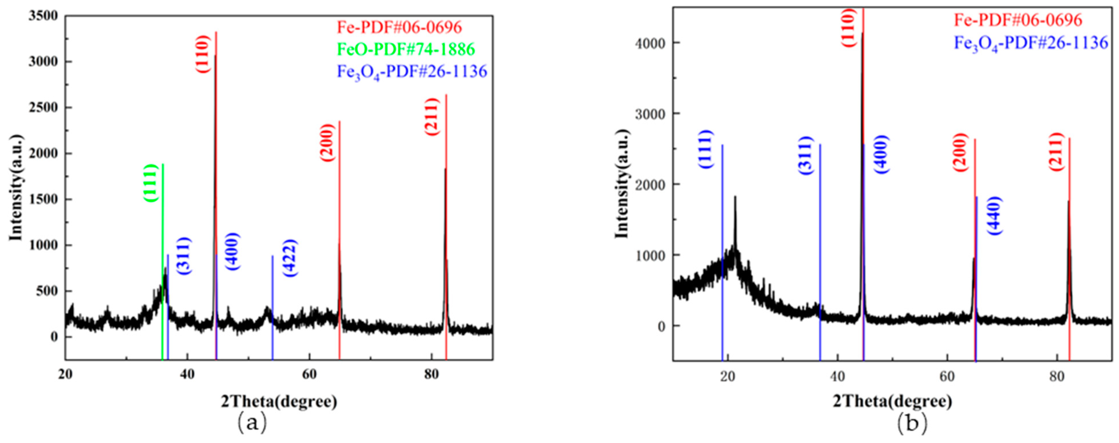
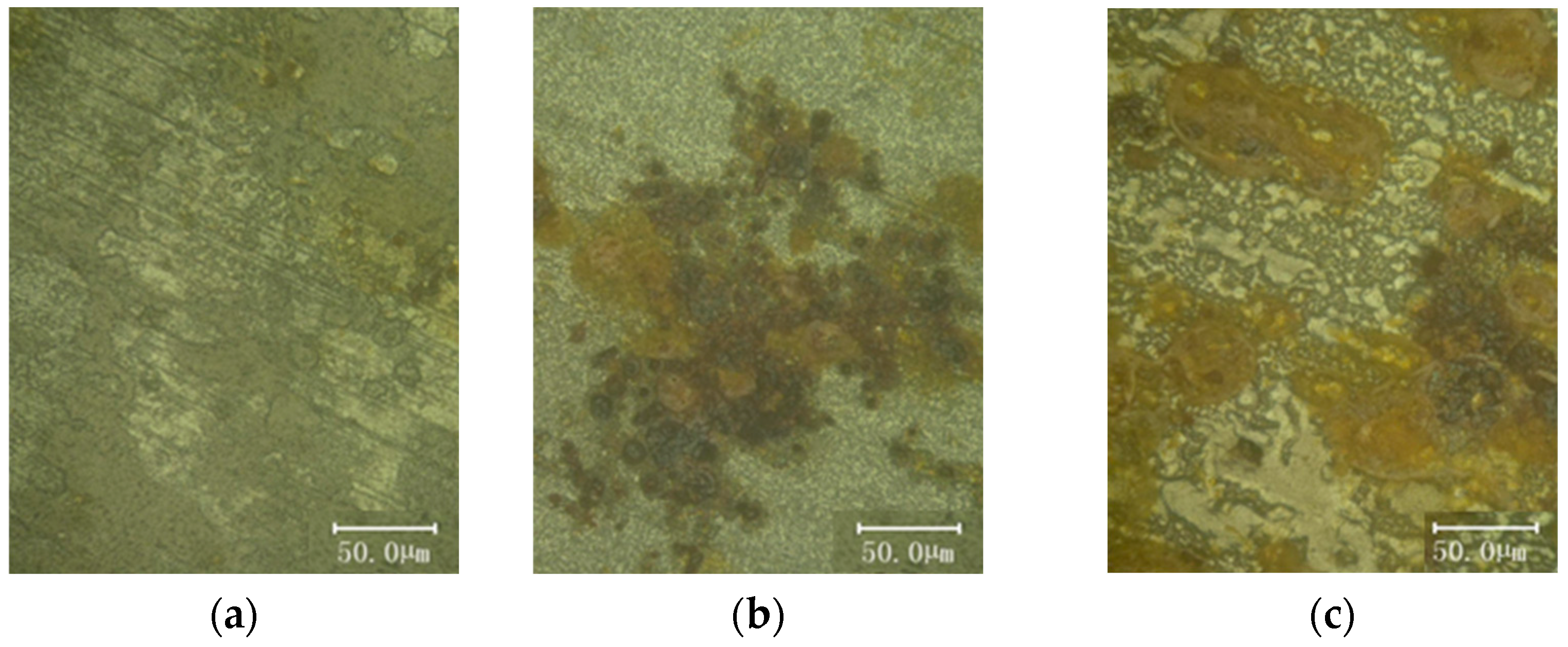
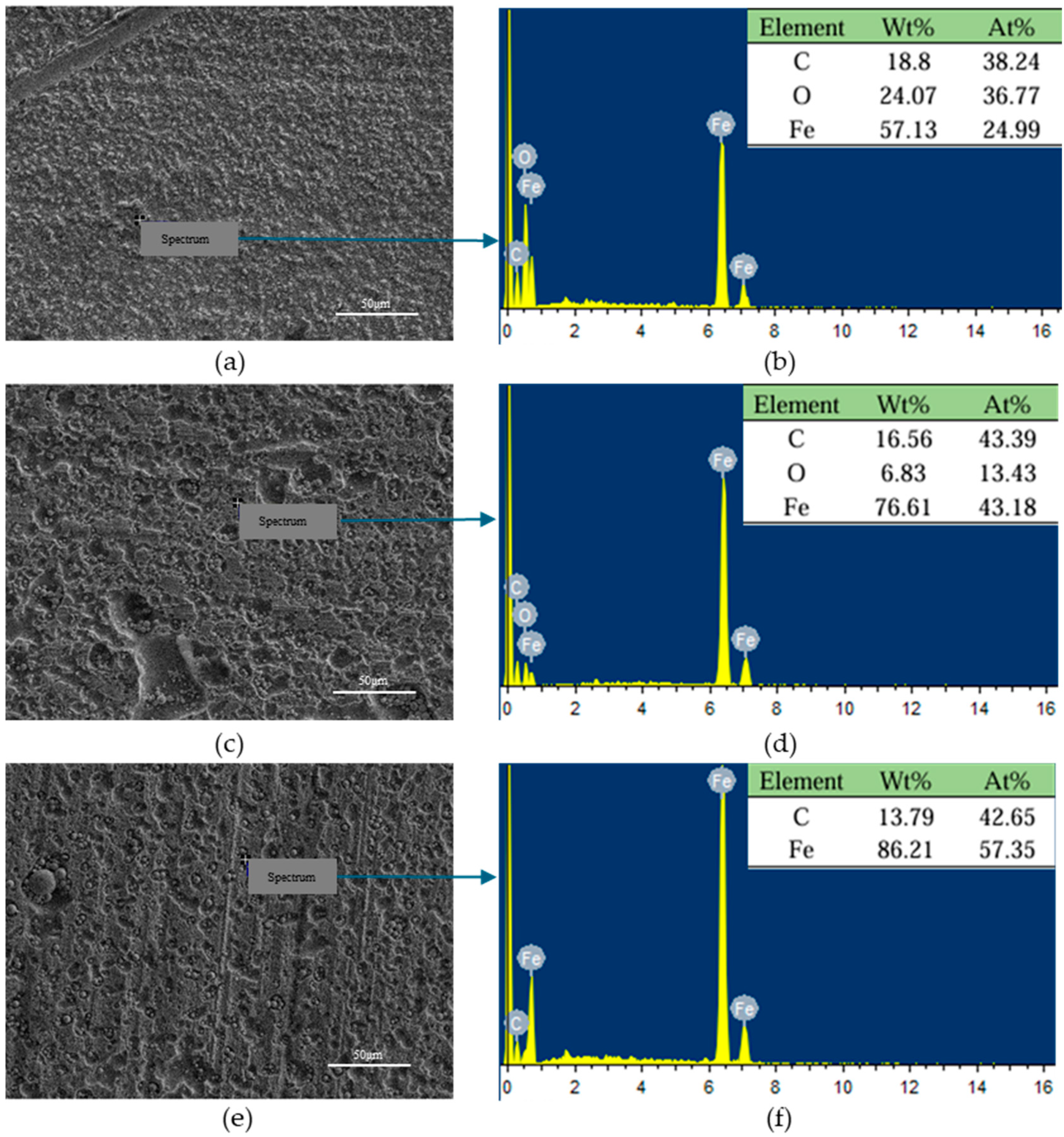
3.2. Microscopic Morphological and Chemical Composition Analysis

The failed samples were further characterized and observed by the SEM and EDS techniques to analyze the cause of the leakage of the pipeline. Different positions on the inner and outer walls of the failed pipeline were selected to observe the morphology and composition of the corrosive products. The SEM images and EDS spectra of the inner and outer walls of the failed pipeline are shown in Figure 3 and Figure 4, respectively. In Figure 3a, the forms of the corrosion products are diverse, including blocky, granular, needle-like, etc. Among them, the structure of the needle-like corrosion products is relatively dense, corresponding to a uniform and dense needle-like iron ore phase [2,30]. Figure 3b–d are the spectra corresponding to the three scanning points in Figure 3a. Location I in Figure 3a is composed of the elements C, O, S, Si, and Fe. The chemical compositions of locations II and III in Figure 3a are composed of the elements C, O, S, and Fe. In Figure 3e, the structure of the corrosion product layer is loose and porous, with poor density, which is due to the fact that Fe3O4 can be dissolved into Fe2+ and Fe3+ in a high-concentration and strongly acidic environment [30]. This loose corrosion product cannot effectively isolate the contact between the metal substrate and the corrosive medium, obviously providing a favorable environment for the invasion of the corrosive medium, resulting in the failure of the protective effect. Figure 3f shows the elemental composition at position II, including C, O, Fe, Mn, etc.
The EDS spectra of Figure 3 show that the O element is enriched on the inner surface, and the Fe element is slightly lost compared to the uncorroded substrate. The high content of the O element indicates that there is a significant oxidation phenomenon on the surface of the sample, and that corrosion products such as Fe3O4 may be formed, which is consistent with the observed surface morphology. The inner wall surface is in direct contact with sulfuric acid. During the corrosion process, some iron dissolves from the matrix into the corrosive environment and diffuses into the solution in the form of ions, which may form soluble corrosion products (such as FeSO4) with sulfate ions through adsorption or coordination. This also explains why a small amount of the S element remains in the elemental composition. It is noteworthy that the EDS spectra of Figure 3 show differences in the S element, which may be caused by the flow rate, temperature or uneven local concentration. Several main components, Si, Mn, etc., are in line with the implementation standards of 20# carbon steel. Trace impurities such as Ca may come from scaling on the inner wall of the pipeline or particles carried by the medium.
Figure 4 shows the SEM images and EDS spectra of the outer wall of the failed part. Compared with Figure 3, the impurity elements (such as Na, K, etc.) in Figure 4 have significantly increased, suggesting that the outer wall surface is exposed to the external environment (such as atmospheric oxidation or pollutant deposition). Moreover, the spectrum at position I did not detect the S element, while a very small amount of the S element was detected at position II, indicating that the corrosion occurred on the inner wall and the perforation leaked to the outer surface.
The XRD patterns of the inner wall of the failed sample are shown in Figure 5. Figure 5a shows the XRD pattern of the corrosive products on the surface, while Figure 5b shows the XRD pattern of the surface gently polished by fine sandpaper. The corrosive substances on the surface of sample are mainly composed of Fe3O4, FeO, and Fe. However, FeO was not detected after being polished. Although EDS provided the elemental composition, sulfides were not detected in the XRD patterns, which might be due to the formation of sulfate thin films resulting in the residue of the S element.
According to the actual working conditions, the waste acid pipe is fed intermittently, and the water vapor in the tank accumulates at the top of the inner tube due to the influence of the temperature difference when the feed is stopped, and mixes with a small amount of wall-mounted sulfuric acid in the pipeline to form a local dilute acid environment, which in turn leads to accelerated corrosion, forming corrosion grooves on the inner surface of the failed pipeline.

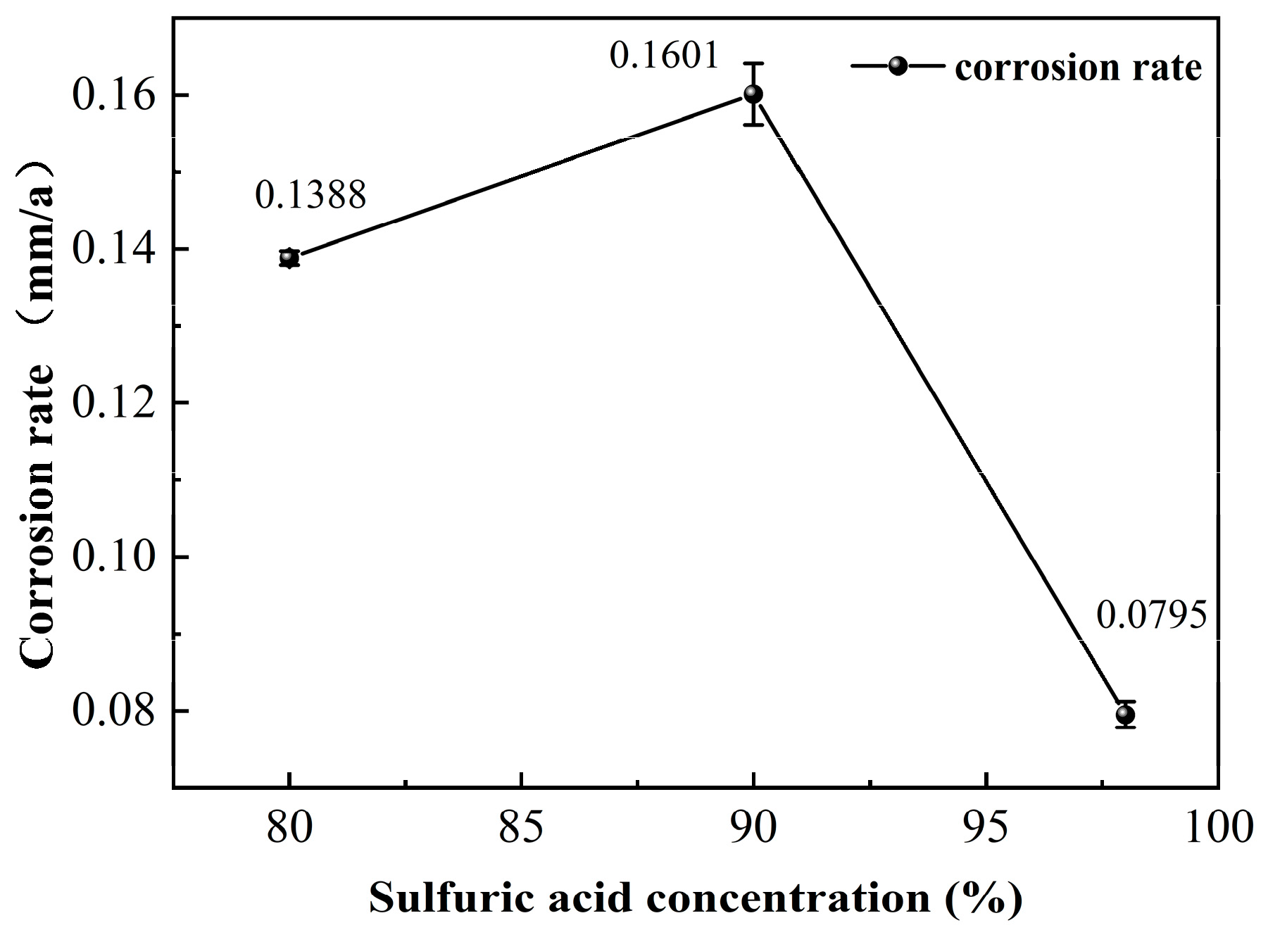
3.3. Immersion Corrosion Results

Figure 6 shows the corrosion rate of 20# steel at different H2SO4 concentrations of 80%, 90%, and 98%. The corrosion rate increases as the concentration of sulfuric acid increases from 80% to 90% at 40 °C. As the concentration of sulfuric acid continues to increase, the corrosion rate decreases rapidly to a minimum value. Because of the strong oxidizing properties [31] of concentrated sulfuric acid, even though the reaction kinetics are accelerated at 40 °C, the synergistic effect of high temperature and concentration still promoted the formation of passivation films and significantly reduced the corrosion rate in 98% H2SO4 solution.
As displayed in Figure 7, the corrosion morphology of the samples in concentrated sulfuric acid environments exhibited a significant concentration-dependent effect. The surface of untreated sample appeared uniform and smooth (Figure 7a), while distinct surface differentiation occurred after corrosion in sulfuric acid solutions with different concentrations (Figure 7b). In 80% H2SO4 solution, the sample surface remained relatively flat overall, with a singular circular etch pit (approximately 2.5 mm in diameter) observed in the central area (red dotted circle line). The light yellow corrosion products were visible. A markedly uneven topography is displayed in 90% H2SO4 solution, featuring a radially expanded central pit surrounded by continuous erosion grooves (red dotted square line). The surface was formed with an orange-yellow substance. In 98% H2SO4 solution, there were no apparent pitting characteristics. However, a dense yellowish-brown film was immediately formed on the surface after rinsing with deionized water, indicating rapid passivation reactions induced by the high-concentration sulfuric acid due to the heat release as the high-concentration sulfuric acid met with water, and diluting sulfuric acid to react with iron.
Figure 8 demonstrates the optical images of the surface of samples corroded in sulfuric acid solutions at three different concentrations. In 80% H2SO4 solution, a small number of micrometer-scale pits were observed with sparse surface oxides (Figure 8a). The sample in 90% H2SO4 solution exhibited uneven discrete distributions of yellow and brown oxides, where the structural integrity of the passivation film was significantly compromised (Figure 8b). In contrast, the sample developed large areas of densely packed blocky yellowish-brown corrosion product layers in 98% H2SO4 solution (Figure 8c), with the passivation film showing only minor damage indications.
The morphology and chemical composition of the surface of the sample corroded by H2SO4 solution were determined and are shown in Figure 9. Figure 9a,c,e show the differences in surface morphology of the samples after corrosion with three concentrations of sulfuric acid. The granular structure is sparsely distributed and there may be local corrosion pitting (Figure 9a). Furthermore, Figure 9c shows a larger particle size and denser distribution, indicating the acceleration of corrosion. Lastly, more complex morphologies (such as peeling) appear on the surface (Figure 9e). Figure 9b,d,f reflect the chemical composition of the surface after corrosion. With the increase in sulfuric acid concentration, the iron content on the surface of the sample increases significantly. The possible reason is that high-concentration sulfuric acid inhibits the corrosion of iron or forms a stable oxide layer to protect the base metal. These micromorphological characteristics demonstrated good correspondence with the macroscopic corrosion of the samples, indicating that gradient variations in sulfuric acid concentration exerted pronounced influences on the material’s surface corrosion behavior. The corroded samples were composed of an Fe phase, with no evidence of the other substances, such as FeSO4 (see the Supporting Information, Figure S1).

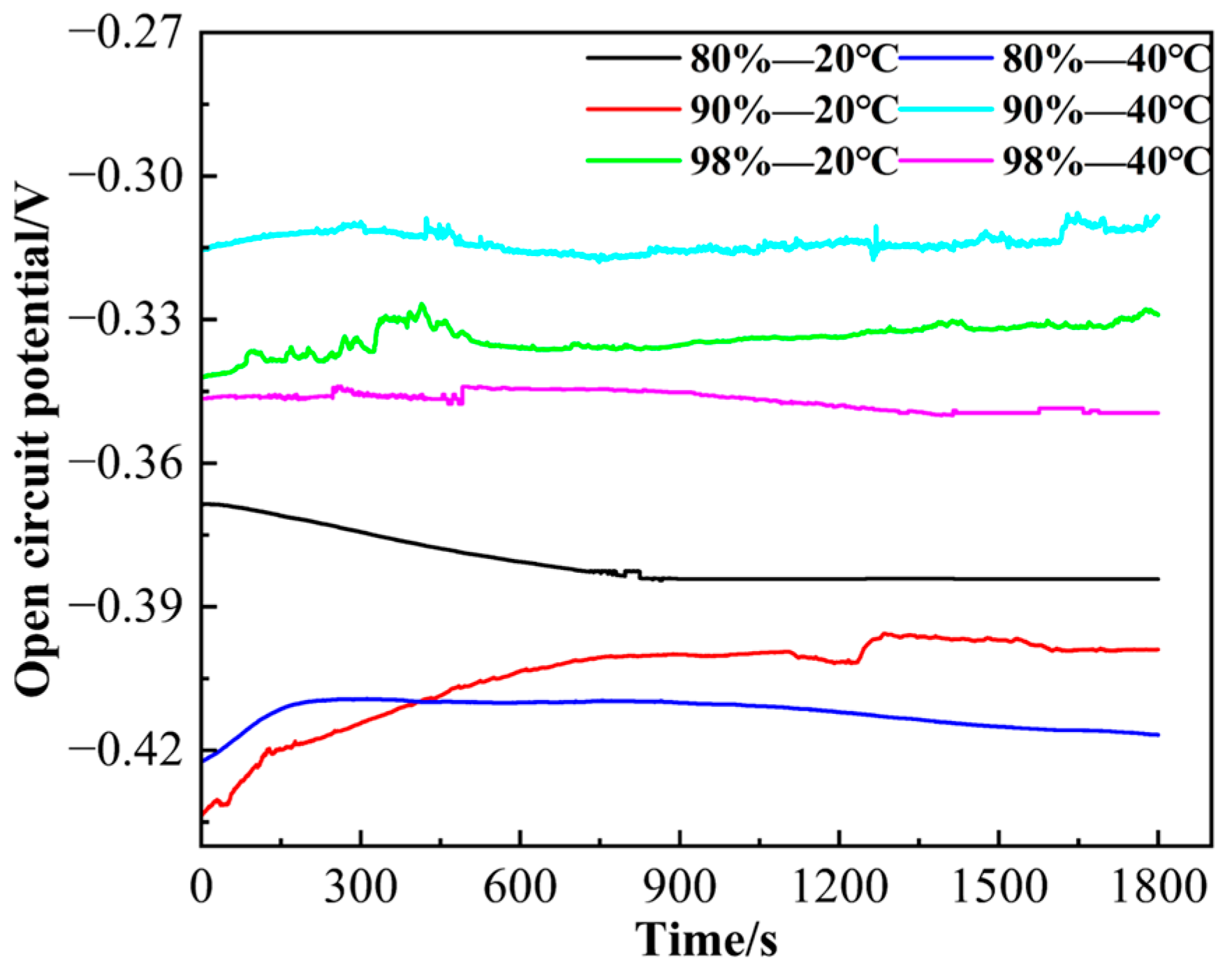
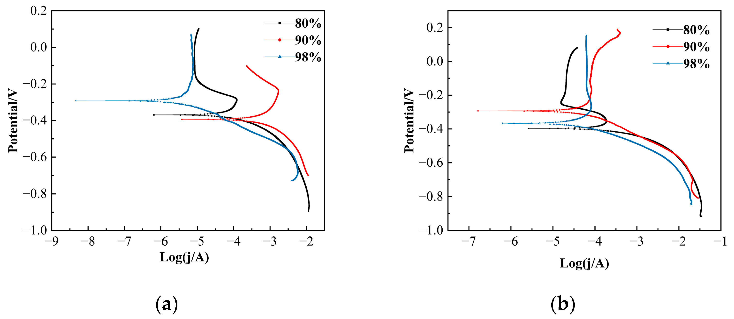
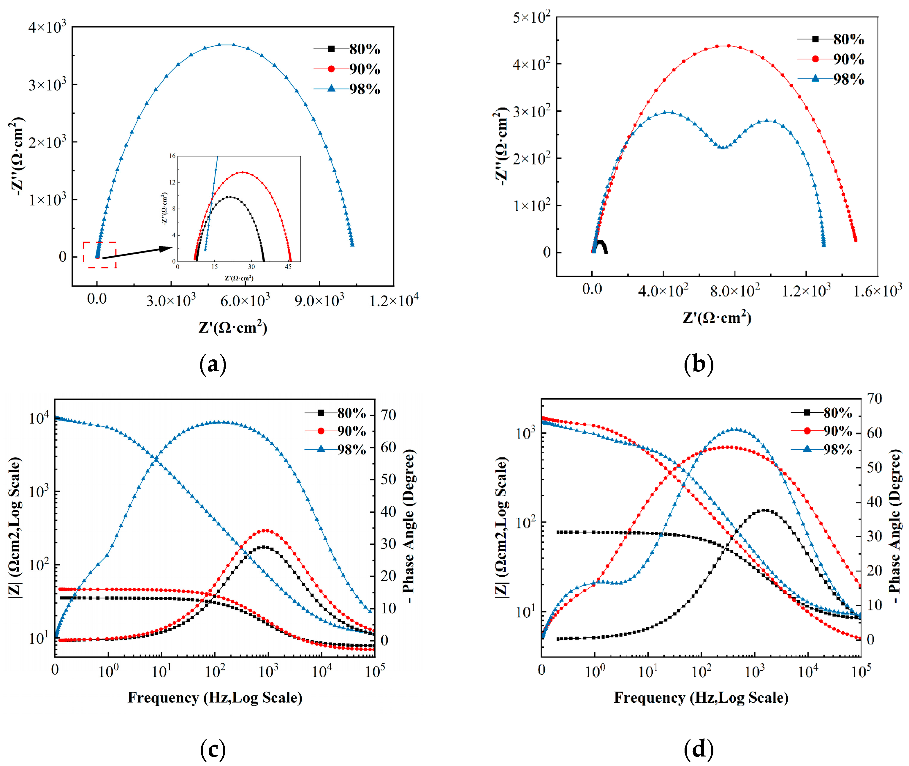
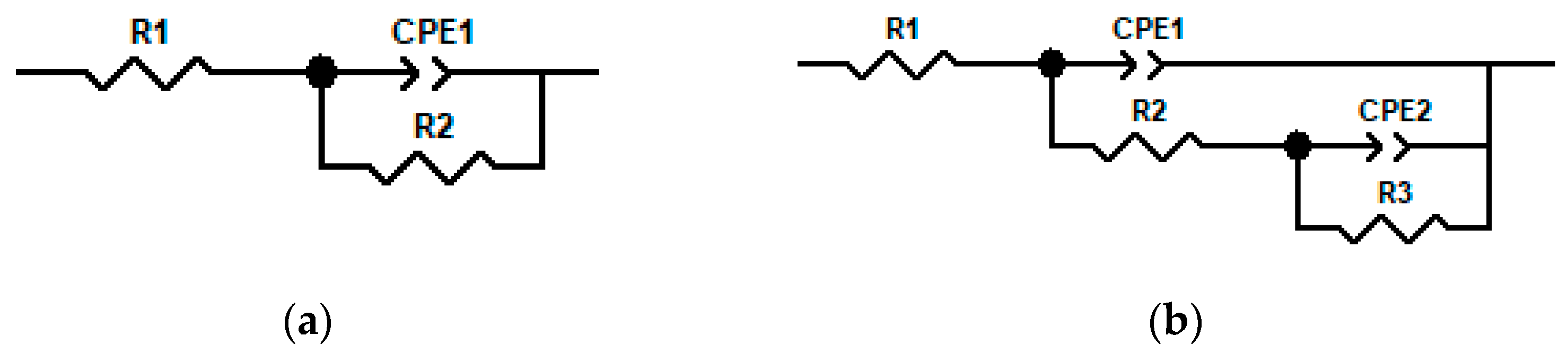
3.4. Electrochemical Corrosion Results

Figure 10 shows the open-circuit potential of 20# carbon steel in different H2SO4 solutions. The open-circuit potential (OCP) reflects the dynamic equilibrium state of REDOX reactions on the electrode surface and is closely related to the thermodynamic stability and corrosion tendency of the material. In general, when the OCP is at a higher potential, the material tends to be in an oxidized state and is more corrosion-resistant. When the OCP is at a lower potential, the material is in a reduced state and may be more active, with a higher tendency for corrosion.
At 20 °C, the potential exhibited a negative shift from −0.369 V at 80% H2SO4 to −0.40 V at 90% H2SO4, suggesting an increase in the tendency for corrosion. Notably, this trend reversed at 98% concentration where the potential rebounded to −0.329 V, attributable to the strong oxidizing nature of concentrated sulfuric acid inducing passivation film formation on the metal surface. Temperature elevation to 40 °C significantly altered the electrochemical behavior. For 80% H2SO4, the potential underwent a pronounced negative shift (−0.416 V vs. −0.369 V at 20 °C), demonstrating the intensified corrosion by temperature. In contrast, 90% H2SO4 displayed an anomalous positive potential shift to −0.309 V, comparable to its 20 °C value (−0.40 V). This inversion implies the thermal promotion of passivation kinetics, likely through accelerated oxide film growth. The 98% concentration system exhibited potential degradation from −0.329 V to −0.345 V, indicative of a partial breakdown in passivation capability under elevated temperatures.
The effect of temperature and concentration of sulfuric acid on the corrosion resistance of 20# steel was studied by potentiodynamic polarization curves and electrochemical impedance spectroscopy. The experimental parameters included temperatures of 20 °C and 40 °C with sulfuric acid concentration gradients of 80%, 90%, and 98%. Figure 11 shows the potential polarization curves of 20# steel in different concentrations of H2SO4 solutions at 20 °C and 40 °C, and the electrochemical parameters obtained by Tafel fitting are shown in Table 2. In Figure 11a, there is a passive region at the anodic region for the carbon steel in 98% H2SO4 solution where the current density was almost kept stable with increasing potential voltage. With an increase in the working temperature, there is a board passive region in 90% H2SO4 solution (Figure 11b), but the current density was increased significantly at the potential of about 0.1 V. In 98% H2SO4 solution, the passive region can be still observed. Therefore, in 98% H2SO4 solution, the passive film can be formed on the surface of the carbon steel, which could protect the steel from corrosion. At high temperatures, the passive films can be easily formed on the surface of the steel in 90% H2SO4 solution compared with the steel in 90% H2SO4 solution at room temperature.
It can be seen from Table 2 that at 20 °C, when the concentration of sulfuric acid increases from 80% to 98%, the corrosion current density jcorr increases from 817.8 μA/cm2 to 2200 μA/cm2 and then drops sharply to 12.742 μA/cm2, which indicates that the corrosion rate is lower at very high concentrations due to the passivation phenomenon, and the strong oxidation of concentrated sulfuric acid promoted the formation of a passivation film on the surface to inhibit corrosion. At 40 °C, the highest corrosion current density of 80% concentration is 489.2 μA/cm2, and the lowest corrosion potential is −0.397 V, indicating that the corrosion rate is relatively high. The jcorr significantly decreased to 212 μA/cm2 with an elevated corrosion potential when the concentration reached 90%. However, in 98% H2SO4 solution, jcorr further decreased accompanied by a slight reduction in corrosion potential, suggesting a continued decline in the corrosion rate and a potential alteration of the corrosion mechanisms. This phenomenon implies that porous or non-compact protective films might form under high-temperature conditions, partially counteracting the temperature-induced acceleration of corrosion.
Under identical concentration conditions, jcorr exhibited non-monotonic variations with temperature elevation from 20 °C to 40 °C. Specifically, in 80% H2SO4 solution, jcorr decreased from 817.8 to 489.2 μA/cm2. In 90% H2SO4 solution, jcorr showed a significant reduction from 2200 to 212 μA/cm2, whereas in 98% H2SO4 solution, jcorr paradoxically increased from 12.742 to 134.3 μA/cm2. This phenomenon demonstrates that the dense and stable passivation film formed under the low-temperature (20 °C) and high-concentration (98%) conditions effectively suppressed corrosion, while the elevated temperature (40 °C) at the equivalent high concentration (98%) accelerated dissolution of the passivation film.
Figure 12 shows the EIS diagrams of 20# carbon steel in different concentrations of H2SO4 solution at 20 °C and 40 °C. The Nyquist plots (Figure 12a,b) were characterized by capacitive semicircular arcs, where the radius magnitude directly correlates with material corrosion resistance. Specifically, larger semicircle radii indicate lower corrosion rates and enhanced corrosion resistance. Notably, the EIS profile exhibited two capacitive arcs in 98% H2SO4 solution at 20 °C, demonstrating double time constants. Phase angle shifts in the Bode plots further reflected variations in time constants under different experimental conditions. As seen from the Bode plots (Figure 12c,d), the impedance modulus |Z| increases significantly at 98% concentration, especially at 20 °C, further supporting the presence of the passivation film. The double peak at the phase angle at 40 °C corresponds to the addition of R3 and Q2 elements in the equivalent circuit, which indicates the occurrence of an interfacial adsorption process or that the structure of the passive films may be changed.
The equivalent circuit models are shown in Figure 13. Figure 13a shows the equivalent circuit at 20 °C and 40 °C, and Figure 13b shows the equivalent circuit under the concentration of 98% H2SO4 solution at 40 °C, where R1 is the resistance of the sulfuric acid solution, R2 is the charge transfer resistance, R3 is the interface reaction resistance, and CPE is the equivalent constant phase angle element. The fitting data for the equivalent circuits are shown in Table 3.
The analysis of R2 values in the table reveals distinct temperature–concentration dependencies. At 20 °C, R2 increased dramatically from 27.15 Ω·cm2 to 10,394 Ω·cm2 with rising concentration, indicating that high concentrations significantly inhibit charge transfer through passivation dominance, where a protective corrosion product layer is formed on the 20# steel surface. Under the concentration of 98% at 40 °C, the R2 value remained substantially higher (877.3 Ω·cm2) than at lower concentrations, though markedly reduced compared to the 20 °C values, demonstrating accelerated passivation film dissolution and partial film failure under elevated temperatures. The elevated temperature induced differential responses in R2 across concentration gradients. At 80% H2SO4, R2 slightly increased. At 90% H2SO4, R2 surged from 39.21 Ω·cm2 to 1487 Ω·cm2, with Nyquist plots demonstrating enlarged semicircular arcs consistent with enhanced interfacial impedance. At 98% H2SO4, R2 plummeted from 10,394 Ω·cm2 to 877.3 Ω·cm2, indicating that the passivation film was damaged under high temperatures, thereby accelerating the corrosion rate.
From the above chart, it can be concluded that the corrosion rate of 20# steel in low concentration (80–90%) H2SO4 solution increases with the increase in concentration and temperature. However, at high concentrations of 98%, the corrosion rate is reduced due to the formation of the passivation film, especially at 20 °C, where the passivation film is the most stable. Combined with the practical application, the case of the sulfuric acid storage tank in the petrochemical plant shows that the annual corrosion rate of 98% sulfuric acid at 20 °C is less than 0.1 mm/a when 20# steel is used to store 98% sulfuric acid, which is in line with the lab results. Intriguingly, 20# steel has a lower cost, a longer maintenance cycle, and better applicability considering the economy.

4. Discussion

The redox properties of sulfuric acid change with the change in concentration and temperature. Sulfuric acid appears as a reducing acid at low concentrations, and as a strong oxidizing acid at concentrations higher than 80 wt.%, containing little free water. Sulfuric acid molecules are dissociated into protons and bisulfate (HSO4) anions; however, undissociated H2SO4 molecules dominate as the concentration increases. The possible chemical reactions are as follows [31].
H S O 4 + 3 H + + 2 e = S O 2 + 2 H 2 O
H 2 S O 4 + 2 H + + 2 e = S O 2 + 2 H 2 O
H S O 4 + 7 H + + 6 e = S + 4 H 2 O
H 2 S O 4 + 6 H + + 6 e = S + 4 H 2 O
H S O 4 + 9 H + + 8 e = H 2 S + 4 H 2 O
H 2 S O 4 + 8 H + + 8 e = H 2 S + 4 H 2 O
At high sulfuric acid concentrations of 80–98 wt.% H2SO4, the anodic reaction (Equation (8)) is followed by the diffusion of Fe2+ ions from the substrate towards the surface of carbon steel where they combine with the SO42− ions to precipitate into a protective layer of insoluble FeSO4. The overall reaction is given by Equation (9).
F e F e 2 + + 2 e
H 2 S O 4 + F e + 7 H 2 O F e S O 4 · 7 H 2 O + H 2
The entire process will be controlled by the diffusion of Fe2+ ions to the solution saturated with SO42− ions followed by the precipitation of the FeSO4 protective film [32]. However, the FeSO4 protective film can be removed by erosion at high flow rates or can be dissolved at high temperatures, accelerating then the corrosion rates. The composition of the passive films formed depends on the H2SO4 concentration and the applied potential [33], and those formed at high concentration are compact and resistant to fast dissolution. The dissolution and diffusion of the FeSO4 film from the surface of carbon steel to the sulfuric acid controls the overall alloy corrosion rate [4].
Moreover, during the flow of high-concentration sulfuric acid in pipelines, a protective corrosion product film dominated by ferrous sulfate spontaneously forms on the pipe wall surface. This protective film exhibits dynamic equilibrium characteristics. Failure analysis indicates that under operating conditions of 40 °C and 98% concentrated sulfuric acid, the pipeline experiences both uniform corrosion and localized corrosion. Uniform corrosion corresponds to the failure of the overall passive film. Electrochemical impedance spectroscopy (EIS) in corrosion experiments exhibits a single arc of capacitive reactance, with only one phase angle peak on the phase angle–frequency diagram, indicating that the electrode reaction is solely controlled by electrochemical processes. In contrast, localized corrosion corresponds to a preferential attack on the defects in the passive film. The EIS shows two capacitive reactance arcs corresponding to double time constants, suggesting the coexistence of two distinct corrosion mechanisms or a multilayer structure of the passive film. Therefore, by integrating failure analysis, immersion corrosion, and electrochemical corrosion, it is concluded that pipeline failure results from the synergistic effects of temperature, acid concentration, the dynamic equilibrium of the passive film, and electrochemical behavior.

5. Conclusions

A comprehensive analysis was conducted on the corrosion failure of the waste acid pipeline components. We found that the corrosion of the pipeline failure was the result of the combined effects of multiple factors, such as acidic corrosion, temperature influence, and instability of the passivation film, etc. In the strongly acidic corrosive medium, both uniform corrosion and localized corrosion existed simultaneously inside the pipeline.
According to the immersion corrosion and electrochemical corrosion, the effect of sulfuric acid concentration on the corrosion rate of 20# carbon steel shows a nonlinear relationship. Pertinently, the corrosion rate increases with increasing concentrations of sulfuric acid at low concentrations (80–90%) and decreases significantly at high concentrations (98%).
The 20# carbon steel exhibits the best corrosion resistance in 98% H2SO4 solution at 20 °C, and had the lowest corrosion rate. Of note, the increment in temperature accelerates the kinetic reaction while weakening the stability of the passivation film, which indicates that concentration and temperature synergistically affect the formation and stability of the passivation film.

Supplementary Materials

The following supporting information can be downloaded at: https://www.mdpi.com/article/10.3390/met15050506/s1, Figure S1: XRD pattern of the corroded samples immersed in 80%, 90%, 98% H2SO4 solutions.

Author Contributions

G.O.: funding acquisition, methodology, investigation, draft manuscript preparation. X.C.: data collection, analysis and interpretation of results, visualization, review, and editing. Y.M.M.: review and editing. W.W.: study conception and design, experiment arrangement, review and editing. All authors have read and agreed to the published version of the manuscript.

Funding

This research received no external funding.

Data Availability Statement

The data supporting this study’s findings are available from the corresponding author upon reasonable request.

Acknowledgments

The authors would like to express their sincere gratitude to the peer reviewers and editors for their insightful comments and constructive suggestions during the review process.

Conflicts of Interest

The authors declare no conflicts of interest.

References

  1. Kim, S.H.; Kang, S.J.; Kim, W.C.; Kim, J.G. Failure analysis of low carbon steel pipeline for district heating and cooling systems: Case studies. Eng. Fail. Anal. 2024, 166, 108826. [Google Scholar] [CrossRef]
  2. Chen, T.; Sun, L.; Li, Q.; Liu, C. Comprehensive analysis of corrosion failure of blast furnace gas pipeline in a steel plant. Eng. Fail. Anal. 2023, 154, 107651. [Google Scholar] [CrossRef]
  3. Al-Mazeedi, H.A.; Al-Wakaa, B.; Ravindranath, K. Window-type rupture of carbon steel pipe in a hydroprocessing plant of a petroleum refinery due to ammonium bisulfide corrosion. Eng. Fail. Anal. 2021, 120, 105089. [Google Scholar] [CrossRef]
  4. Ellison, B.T.; Schmeal, W.R. Corrosion of steel in concentrated sulfuric acid. J. Electrochem. Soc. 1978, 125, 524. [Google Scholar] [CrossRef]
  5. Panossian, Z.; de Almeida, N.L.; de Sousa, R.M.F.; de Souza Pimenta, G.; Marques, L.B.S. Corrosion of carbon steel pipes and tanks by concentrated sulfuric acid: A review. Corros. Sci. 2012, 58, 1–11. [Google Scholar] [CrossRef]
  6. Yue, Y.; Liu, C.; Asselin, E.; Shi, P.; Jiang, M. Kinetics of passive film growth on 304 stainless steel in H2SO4 pickling solution under chemical oxidation. Corrosion 2018, 74, 705–714. [Google Scholar] [CrossRef]
  7. Javidi, M.; Abadeh, H.K.; Namazi, F.; Yazdanpanah, H.R.; Shiri, N.S. A new perspective on the corrosion of carbon steels in H2SO4 acid environments: Statistical analysis of corrosion mechanisms by response surface modeling. Mater. Chem. Phys. 2024, 312, 128608. [Google Scholar] [CrossRef]
  8. Burstein, G.T.; Daymond, B.T. The remarkable passivity of austenitic stainless steel in sulphuric acid solution and the effect of repetitive temperature cycling. Corros. Sci. 2009, 51, 2249–2252. [Google Scholar] [CrossRef]
  9. Sato, N. An overview on the passivity of metals. Corros. Sci. 1990, 31, 1–19. [Google Scholar] [CrossRef]
  10. Li, Y.; Zhang, Z.; Wu, Q.; Gu, J.; Baker, I.; Song, M. Enhanced corrosion resistance of FeCoCrNiMn high-entropy alloy in aqueous H2SO4 solutions by N and Si alloying. J. Mater. Eng. Perform. 2025, 1–12. [Google Scholar] [CrossRef]
  11. Sun, Y.; Liu, W.; Chen, L.; Zhang, T.; Li, H.; Zhang, B.; Yang, W.; Cui, J.; Hou, B.; Wang, F.; et al. The dual nature of Cu content on the corrosion resistance of low alloy steels in sulfuric acid: A time-dependent reversal of corrosion resistance. Corros. Sci. 2023, 224, 111486. [Google Scholar] [CrossRef]
  12. Fujimura, A.; Abe, M.; Kawano, A.; Iwai, M.; Kitano, S.; Habazaki, H.; Fushimi, K. Effect of Al and Si addition on passivation of stainless steels in H2SO4 solution. Corros. Sci. 2024, 227, 111756. [Google Scholar] [CrossRef]
  13. Cabral-Miramontes, J.; Cabral-Miramontes, N.; Nieves-Mendoza, D.; Lara-Banda, M.; Maldonado-Bandala, E.; Olguín-Coca, J.; Lopez-Leon, L.D.; Estupiñan-Lopez, F.; Calderon, F.A.; Gaona Tiburcio, C. Anodizing of AA2024 aluminum–copper alloy in citric-sulfuric acid solution: Effect of current density on corrosion resistance. Coatings 2024, 14, 816. [Google Scholar] [CrossRef]
  14. Trentin, A.; Mardoukhi, A.; Lambai, A.; Pohjanne, P.; Huttunen-Saarivirta, E. Pitting corrosion of austenitic and duplex stainless steels in dilute acids at elevated temperature: Effect of electrolyte chemistry and material microstructure. Corros. Sci. 2025, 247, 112769. [Google Scholar] [CrossRef]
  15. Hayashida, S.; Takahashi, M.; Deguchi, H.; Tsuchiya, H.; Hanaki, K.; Yamashita, M.; Fujimoto, S. Structure of corrosion product formed on carbon steel covered with NiSO4-added resin coating under sulfuric acid mist environment containing chloride. Mater. Trans. 2021, 62, 781–787. [Google Scholar] [CrossRef]
  16. Gola, K.; Ledwig, P.; Dubiel, B. Effect of microstructure of additively manufactured Inconel 625 on long-term corrosion behaviour in sulfuric acid media. JOM 2023, 75, 1242–1250. [Google Scholar] [CrossRef]
  17. Chowdhury, M.A.; Reza, M.S.; Hossain, N.; Ali, M.R.; Kowser, M.A.; Shuvho, M.B.A. Improvement of corrosion resistance of galvanization/nickel/chrome plating low carbon steels in H2SO4 under dynamic condition. Surf. Topogr. Metrol. Prop. 2021, 9, 035018. [Google Scholar] [CrossRef]
  18. Javidi, M.; Abadeh, H.K.; Yazdanpanah, H.R.; Namazi, F.; Shiri, N.S. Synergistic effect of temperature, concentration and solution flow on corrosion and passive film of austenitic SS 304L and 316L in concentrated sulfuric acid. Corros. Sci. 2024, 237, 112306. [Google Scholar] [CrossRef]
  19. Ouarga, A.; Zirari, T.; Fashu, S.; Lahcini, M.; Youcef, H.B.; Trabadelo, V. Corrosion of iron and nickel based alloys in sulphuric acid: Challenges and prevention strategies. J. Mater. Res. Technol. 2023, 26, 5105–5125. [Google Scholar] [CrossRef]
  20. Huttunen-Saarivirta, E.; Isotahdon, E.; Lindgren, M.; Mardoukhi, A.; Mocnik, P.; Kosec, T.; Jorcin, J.B.; Mameng, S.H.; El Ouazari, Y.; Wegrelius, L. Corrosion of stainless steels S31603, S31655, and S32101 in sulfuric acid solutions: Effects of concentration, chlorides, and temperature. Corrosion 2022, 78, 943–962. [Google Scholar] [CrossRef]
  21. Abdelfatah, A.; Raslan, A.M.; Mohamed, L.Z. Corrosion characteristics of 304 stainless steel in sodium chloride and sulfuric acid solutions. Int. J. Electrochem. Sci. 2022, 17, 220417. [Google Scholar] [CrossRef]
  22. Fattah-Alhosseini, A.; Golozar, M.A.; Saatchi, A.; Raeissi, K. Effect of solution concentration on semiconducting properties of passive films formed on austenitic stainless steels. Corros. Sci. 2010, 52, 205–209. [Google Scholar] [CrossRef]
  23. Boissy, C.; Alemany-Dumont, C.; Normand, B. EIS evaluation of steady-state characteristic of 316L stainless steel passive film grown in acidic solution. Electrochem. Commun. 2013, 26, 10–12. [Google Scholar] [CrossRef]
  24. Tang, J.; Zhang, Z.; Wang, Y.; Ju, P.; Tang, Y.; Zuo, Y. Corrosion resistance mechanism of palladium film-plated stainless steel in boiling H2SO4 solution. Corros. Sci. 2018, 135, 222–232. [Google Scholar] [CrossRef]
  25. Huang, K.; Zhou, X.; Guo, H.; Chen, Y. Thermal annealing effect on the corrosion resistance of AlCuNiTiZr high entropy alloy films in sulfuric acid solution. Thin Solid Film. 2021, 730, 138707. [Google Scholar] [CrossRef]
  26. Tao, S. 1-Phenyl-1H-tetrazol as corrosion inhibitor for pipeline steel in sulfuric acid solution. Int. J. Electrochem. Sci. 2021, 16, 210335. [Google Scholar] [CrossRef]
  27. Chen, Z.; Liu, Z.; He, K.H.; Han, G.-C.; Lv, Y.; Han, J.; Wei, X. Two diamine Schiff base as a corrosion inhibitors for carbon steel in sulfuric acid solution: Electrochemical assessment and theoretical calculation. Int. J. Electrochem. Sci. 2021, 16, 210559. [Google Scholar] [CrossRef]
  28. Gapsari, F.; Setyarini, P.H.; Anam, K.; Hadisaputra, S.; Hidayatullah, S.; Purnami; Sulaiman, A.M.; Lai, C.W. Efficacy of Andrographis paniculata leaf extract as a green corrosion inhibitor for mild steel in concentrated sulfuric acid: Experimental and computational insights. Results Surf. Interfaces 2025, 18, 100361. [Google Scholar] [CrossRef]
  29. Peng, W.; Hou, J.; Ding, K.; Guo, W.; Qiu, R.; Xu, L. Corrosion Behavior of 304 Stainless Steel in Deep Sea Environment. J. Chin. Soc. Corros. Prot. 2019, 39, 145–151. (In Chinese) [Google Scholar]
  30. Chenghui, Y.; Jinshuo, L.I.; Qiang, Y.U.; Wang, H.; Li, B.; Wu, J.; Chaofang, D.; Xiao, K. Corrosion behaviour and mechanism of acid-resistant steel in acidic solutions with different Cl concentrations. J. Mater. Res. Technol. 2024, 30, 7242–7255. [Google Scholar] [CrossRef]
  31. Richardson, J.A. Corrosion in sulfuric acid. Shreir’s Corros. 2010, 2, 1226–1249. [Google Scholar]
  32. Dean, S.W.J.; Grab, G.D. Corrosion of carbon steel tanks in concentrated sulfuric acid service. Mater. Perform. 1986, 25, 48–52. [Google Scholar]
  33. Gilli, G.; Zucchi, F. Diffractometric analysis of the products of anodic oxidation of Fe in concentrated H2SO4. Corros. Sci. 1968, 8, 801–808. [Google Scholar] [CrossRef]
Figure 1. Process flow chart of acid storage tank.
Metals 15 00506 g001
Figure 2. Digital images of the inside (a) and outside (b) of the failed pipelines.
Metals 15 00506 g002
Figure 3. SEM images and EDS spectra of the inner wall of the failed part at the different locations: (ad) location I (b) Spectrum I; (c) Spectrum II; (d) Spectrum III and (e,f) location II.
Metals 15 00506 g003
Figure 4. SEM images and EDS spectra of the outer wall of the failed part at the different locations: (a,b) location I and (c,d) location II.
Metals 15 00506 g004
Figure 5. XRD patterns of the inner surface of the failed sample. Corrosive products (a) unpolished and (b) polished.
Metals 15 00506 g005
Figure 6. Corrosion rate of 20# carbon steel in different concentrations of H2SO4 solution.
Metals 15 00506 g006
Figure 7. Digital macrographs of the carbon steel before (a) and after (b) immersion corrosion.
Metals 15 00506 g007
Figure 8. Optical micrographs of the surface of the corroded sample in 80% (a), 90% (b), and 98% (c) H2SO4 solutions.
Metals 15 00506 g008
Figure 9. SEM image and EDS spectrum of the surface of the corroded sample in 80% (a,b), 90% (c,d), and 98% (e,f) H2SO4 solutions.
Metals 15 00506 g009
Figure 10. Open-circuit potentials of 20# carbon steel in concentrated H2SO4 solutions.
Metals 15 00506 g010
Figure 11. Polarization curves of the carbon steel in different concentrations of H2SO4 solutions at 20 °C (a) and 40 °C (b).
Metals 15 00506 g011
Figure 12. EIS diagrams of 20# carbon steel in different concentrations of H2SO4 solutions at 20 °C (a,c) and 40 °C (b,d).
Metals 15 00506 g012
Figure 13. Equivalent circuits of the steel in (a) H2SO4 solution and (b) in 98% H2SO4 solution at 40 °C.
Metals 15 00506 g013
Table 1. Chemical composition of 20# carbon steel (wt.%).
CSiMnPSCrNiCu
0.210.310.580.0180.0030.120.0010.002
Table 2. Electrochemical corrosion parameters of polarization curves.
H2SO4 (wt.%)T (°C)ba (V/dec)bc (V/dec)Ecorr (V)jcorr (μA/cm2)
80200.15310.1195−0.3695817.8
90200.16700.3557−0.39502200
98200.000110.5571−0.29212.742
80400.11900.0927−0.397489.2
90400.11931.0989−0.293212
98400.091450.9478−0.367134.3
Table 3. Fitting parameters of electrochemical impedance spectroscopy.
T/°Cwt.%ECR1/Ω·cm2R2/Ω·cm2R3/Ω·cm2n1n2Q1/μF·cm2Q2/μF·cm2χ2
2080(a)7.70627.15——0.79686.45——2.76 × 10⁻³
4080(a)7.69527.35——0.79389.13——3.86 × 10⁻³
2090(a)6.77339.21——0.76987.38——1.43 × 10⁻³
4090(a)4.0571487——0.67976.19——6.47 × 10⁻³
2098(a)10.6210394——0.78615.73——9.40 × 10⁻³
4098(b)7.09877.3429.50.7591.028.19580.43.02 × 10−3
Note: EC—Equivalent circuits in Figure 13.
Disclaimer/Publisher’s Note: The statements, opinions and data contained in all publications are solely those of the individual author(s) and contributor(s) and not of MDPI and/or the editor(s). MDPI and/or the editor(s) disclaim responsibility for any injury to people or property resulting from any ideas, methods, instructions or products referred to in the content.

