Article

Fatigue Threshold and Microstructure Characteristic of TC4 Titanium Alloy Processed by Laser Shock

1
School of Mechanical Engineering, Hebei University of Technology, Tianjin 300401, China
2
Center for Advanced Laser Technology, School of Electronics and Information Engineering, Hebei University of Technology, Tianjin 300401, China
3
Key Laboratory of Hebei Province on Scale-Span Intelligent Equipment Technology, Tianjin 300401, China
*
Author to whom correspondence should be addressed.
Metals 2025, 15(4), 453; https://doi.org/10.3390/met15040453
Submission received: 17 March 2025 / Revised: 4 April 2025 / Accepted: 14 April 2025 / Published: 17 April 2025
(This article belongs to the Special Issue Laser Shock Peening: From Fundamentals to Applications)

Abstract

:
Laser shock peening (LSP) is an effective method to improve the fatigue property of metallic materials, and a thorough understanding of its strengthening mechanism is crucial for technology application. In this study, the LSP and fatigue tests of TC4 titanium alloy have been carried out. Combined with the structural characterization and the crystal plasticity finite element (CPFE) simulation, the relationship of stress distribution, microstructure evolution and fatigue performance caused by LSP is revealed. The results indicate that the material’s fatigue life initially increases and subsequently declines with the rising pulse energy. At the optimal pulse energy condition, the laser-shocked specimen demonstrates a 126% increase in fatigue life relative to the untreated specimen, which is accompanied by the higher residual compressive stress along the depth. Meanwhile, the grains become more refined with a uniform size change gradient, and the β phase content drops from 4.1% to 2.2%. Notably, regions with < 1 - 2 1 - 0> crystal orientation can be selectively achieved. With the favorable < 1 - 2 1 - 0> slip direction orthogonal to the applied fatigue loading axis, the generation and propagation of dislocations are effectively constrained, thereby significantly enhancing the material’s fatigue performance. The stress distribution and fatigue life in models with different grain sizes and phase contents are further analyzed by the CPFE method, showing good consistency with the experimental results. Theoretically, the excessively high pulse energy causes the transient temperature (1769 °C) to surpass the melting point (1660 °C), which can affect the recrystallization structure and stress distribution.

1. Introduction

TC4 as a dual-phase titanium alloy has been extensively utilized in industries such as aviation, aerospace, shipbuilding, etc., owing to its high strength, heat resistance and corrosion resistance [1,2,3]. However, with the advancement of high-end equipment and the increased service requirement, enhancing the fatigue performance of titanium alloy has become a critical research focus in recent years [4]. Laser shock peening (LSP) is a metal surface modification technology, which uses a controllable high-energy pulsed laser to induce shock waves and achieve surface strengthening. Compared with the traditional strengthening method, LSP can effectively maintain the surface integrity of the material and significantly improve the fatigue strength and service life [5,6,7].
The fatigue performance of laser-treated material is closely associated with the impact parameters, such as laser power density, pulse width, and so on [8]. According to the relationship between laser power density and peak pressure [9], the higher pulse energy in per unit time and area generally produces the stronger peak pressure; however, the corresponding fatigue performance does not necessarily exhibit a positive correlation. Hu et al. [10] found that the fatigue life of 2060 aluminum alloy exhibited a non-monotonic response to the laser power density, first increasing to an optimum level before decreasing with excessive energy. A similar phenomenon has also been observed in other aluminum alloy, nickel-based single-crystal high-temperature alloy and so on [11,12]. However, in the existing studies of titanium alloys, it was observed that the fatigue life was usually proportional to the pulse energy [13,14,15], and few research studies exhibited the threshold phenomenon [16]. Wang et al. [16] revealed that the excessive impact energy could cause the surface microstructure damage, leading to reduced fatigue life in TC4 alloy. Therefore, the mechanical behavior and strengthening mechanism of laser impact on titanium alloy need to be further studied.
Under the ultra-high strain rate induced by LSP with variable parameters, the plastic deformation can occur on the metal surface to different degrees, leading to the differences in residual stress and microstructure characteristics. The depth of the residual stress field introduced through LSP can exceed 800 μm. This can help to resist crack initiation and propagation under cyclic loading, thereby reducing the stress concentration factor and significantly enhancing the fatigue property [17,18,19]. In general, the laser shocked metal is always accompanied by the grain refinement. Due to the two-phase combination of hexagonal close-packed structure (α phase) and face-centered cubic structure (β phase) of TC4 titanium alloy, the microstructure evolution mechanism under LSP is much more complicated [20,21,22,23]. Ren et al. [24] found that the laser shock triggered multidirectional twin interaction and dislocation slip in the α phase, along with high-density dislocation entanglement in the β phase, collectively promoting the grain refinement. Ouyang et al. [25] revealed that LSP-induced dislocation motions could promote both the tilting and sliding of α and β phase crystals, leading to the formation of a core–shell structure in the titanium grains and a gradient grain structure extending from the surface to the interior, thereby enhancing the mechanical properties of hot-forged TC4 alloy. Furthermore, the improvement of fatigue performance can also been realized by regulating the proportion of the phase structure [26,27,28]. Therefore, the relationship among the microstructure evolution mechanism, fatigue property and LSP parameters on TC4 titanium alloy requires further investigation.
In this paper, the strengthening behavior and relative mechanism of TC4 titanium alloy by LSP is systematically studied using the laser shock test, fatigue test and crystal plasticity finite element (CPFE) simulation. The fatigue threshold phenomenon and microstructure evolution are revealed and discussed. Furthermore, the temperature rise effect of laser shock and its role in residual stress distribution are also analyzed. The results will afford an important theoretical and practical significance for optimizing LSP process parameters and improving the mechanical property of titanium alloy.

2. Models and Methods

2.1. LSP Treatment

A TC4 plate (Baoti Group Co., Ltd., Baoji, China) was prepared with the thickness of 1.5 mm. It was followed by stepwise grinding and polishing using 180# to 2000# sandpaper, ultrasonic cleaning with ethanol, and air drying. The SCG-Extra laser (Suzhou S.C. New Energy Technology Co., Ltd., Suzhou, China) was used for laser impact with a spot diameter of 2 mm and a lap rate of 50%. The pulse width and the impulse frequency were separately set at 10 ns and 5 Hz. The energy levels of 2.5 J to 6.5 J were, respectively, applied on both sides using an “S” type impact pattern, as shown in Figure 1c. The 3M aluminum foil that was 200 μm thick served as the absorbing layer, and flowing water 1 mm thick was used as the restraining layer, as shown in Figure 1a.

2.2. Fatigue Test

After the laser impact, the plate was processed into some standard fatigue specimens through the wire cutting. The specimen size and impact area are, respectively, shown in Figure 1b,c. The tensile fatigue test was carried out using the MTS 809.02 servo-hydraulic fatigue testing machine(MTS Systems Corporation, Eden Prairie, MN, USA) at room temperature (Figure 1d). The fatigue test stresses of 600–900 MPa were examined, revealing that the higher stress caused the excessive life variability while the lower stress prolonged the testing duration unnecessarily. Therefore, a maximum test stress of 720 MPa was selected with a conventional loading frequency of 5 Hz. The stress ratio R = 0.1 was chosen based on the fatigue testing standard (ASTM E466-21 [29]). Testing was conducted following standard failure criteria until complete specimen fracture occurred. Four replicate fatigue tests were performed for each pulse energy condition to ensure statistical reliability. The fatigue fracture morphology was observed by an Olympus optical microscope. A comparative examination of surface microstructures was conducted before and after laser processing via the Thermo Scientific Apreo 2C Electron Backscattered Diffraction (EBSD) (Thermo Fisher Scientific, Waltham, MA, USA). The AztecCrystal 7.0 software was used for particle size measurement, distribution statistics, and other analyses.

2.3. Numerical Simulation

2.3.1. CPFE Theory

The influence of various parameters on the fatigue strength was further studied by the CPFE method. The crystal plasticity model used in this paper was proposed by Taylor [30], which includes the deformation geometry, mechanical constitutive relationship, and strain-hardening behavior. The total strain-deformation gradient F is decomposed into elastic strain F e and plastic strain F p , which can be denoted as shown below:
F = F e F p
Additionally, the velocity gradient of the final configuration L can be resolved into elastic and plastic components:
L = F ˙ F 1 = L e + F e L p F e 1
Here, F ˙ and F 1 , respectively, represent the derivative and inverse of the deformation gradient F . L e is the elastic portion, and the plastic component of the velocity gradient L p is generated by a combination of slip and twinning. The rate of the plastic deformation gradient is given by the following relationship:
L p = α γ ˙ α S α
S α = m α n α
Here, α represents the corresponding slip system, γ ˙ is the plastic shear rate, S is the Schmid tensor of the slip system, m is a unit vector in the slip direction of the slip system, and n is a normal vector on the slip surface.
There is an exponential relationship between the shear strain rate and the slip shear force:
γ ˙ α = γ ˙ α τ α g α τ α g α n 1
where τ is the resolved shear stress, g is the slip resistance, n is the shear strain sensitivity coefficient, and the slip resistance is dislocation-dependent, so there is an expression for the slip resistance:
g ˙ α = h α β γ ˙ β
where g ˙ represents the rate of change in slip resistance, and h α β denotes the hardening modulus between slip coefficients. If α = β , it denotes the self-hardening modulus, and if α β , it indicates the latent hardening modulus.
The self-hardening modulus is expressed as shown below:
h α α = h γ = h 0 sech 2 h 0 γ τ s τ 0
γ = α 0 t γ ˙ α d t
where h 0 is the initial hardening modulus, γ is the cumulative shear strain for all slip coefficients, τ 0 is the yield stress that is the same as the initial value of the critical shear stress, and τ s is the critical stress at which the macro-plastic flow occurs.
The latent hardening modulus is written as shown below:
h α β = q h γ α β
Here, q is the hardening parameter ratio, which is taken as “1” by default.

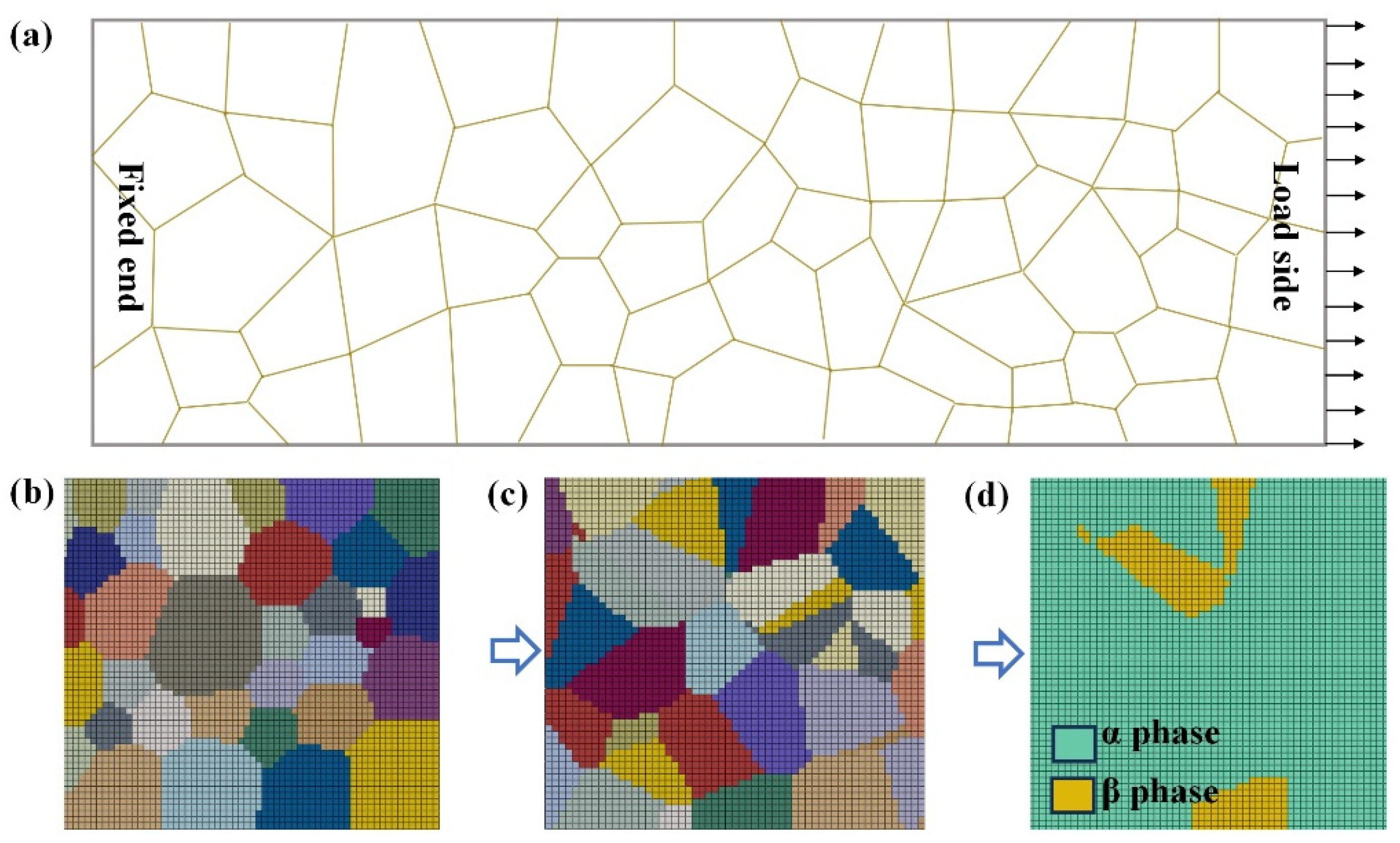
2.3.2. CPFE Modeling

The ABAQUS 6.16 finite element analysis software was employed to explore the impact of various crystal parameters on the fatigue performance of TC4 titanium alloy. The specific implementation processes were as follows: Firstly, a 3D Voronoi seed and models were created through Matlab 2022a and Neper 3.7 software. Subsequently, the material properties and crystal orientations were assigned by the Python 3.8 program. Finally, a self-written UMAT user material subroutine was introduced into ABAQUS to perform the simulations. The intrinsic material parameters are presented in Table 1 [31].
A crystal plasticity model with dimensions of 1.2 mm × 0.6 mm × 0.15 mm was created using the aforementioned methodology. As shown in Figure 2, the model comprised 100 grains and was divided by C3D8R mesh elements. The grain boundary generally plays a pivotal role in governing crack formation and propagation behavior. Therefore, the influences of grain size and phase composition on the stress concentration and fatigue behavior were focused based on the EBSD characterization. Three types of microstructures were considered: (1) an inhomogeneous α model consisting of an α phase with randomly generated grain size (Figure 2b); (2) a homogeneous α model featuring an α phase with a relatively uniform grain size (Figure 2c); and (3) a dual-phase model based on the homogeneous α model that included the addition of β phase constitutive parameters (Figure 2d). Boundary conditions were set with one side fixed and the other side subjected to the stress of 720 MPa, which was consistent with the experimental conditions. Then, the calculation result files were imported into Fe-safe software (Simulia 2022) for fatigue analysis. The numerical process for fatigue calculation aligned with the parameter setting of the fatigue testing procedure.

3. Results

3.1. Fatigue Life and Fracture Morphology

Figure 3 presents the fatigue life of the specimen, respectively, treated with the pulse energy (E) of 2.5 J–6.5 J. All experiments were performed under a maximum stress of 720 MPa with a stress ratio of 0.1. A fatigue threshold of the specimen emerges as the pulse energy increases. The average cycle number of the unimpacted specimens is 10,412, while the maximum cycle value of 23,551 is achieved at E = 3.5 J, representing the fatigue life increasing by 126%. However, the further increase in pulse energy can lead to a reduction rather than improvement in fatigue life. When the pulse energy ranges from 4.5 to 6.5 J, the fatigue life of the specimen shows negligible improvement compared to the untreated sample.
Three representative specimens with the pulse energy of 0 J, 3.5 J, and 6.5 J are selected for comparative fatigue fracture analysis. The fatigue fracture surface of untreated specimens exhibits a relatively smooth morphological feature. This indicates a faster crack propagation rate under fatigue loading and a shorter crack initiation stage. The fracture of the sample strengthened by laser impact at E = 3.5 J displays a rougher surface texture with a more tortuous fatigue crack propagation path and well-defined fatigue striations. The maximum pit depth on the fracture surface of repeated specimens ranged from 100 μm to 140 μm with a corresponding width of 200 μm~250 μm. In the sample treated by laser impact at E = 6.5 J, the fracture morphology shows intensified plastic deformation, which may be due to the microcracks and the thermal damage caused by higher pulse energy. At this stage, the pit depth on the fracture surface increased to approximately 250~400 μm, and the width expanded to approximately 350~500 μm.
An appropriate energy range exists in the LSP process beyond which the material’s fatigue life is negatively affected. Based on the fracture morphology and fatigue life results, it is concluded that the pulse energy of 3.5 J is optimal, as it maximizes the surface residual compressive stress and inhibits the initiation and propagation of cracks. In contrast, excessively high pulse energy can cause the surface damage, impairing the fatigue performance enhancement. Furthermore, the specimens at E = 0 J, 3.5 J, and 6.5 J are subsequently selected for surface characteristic to investigate the underlying mechanisms.

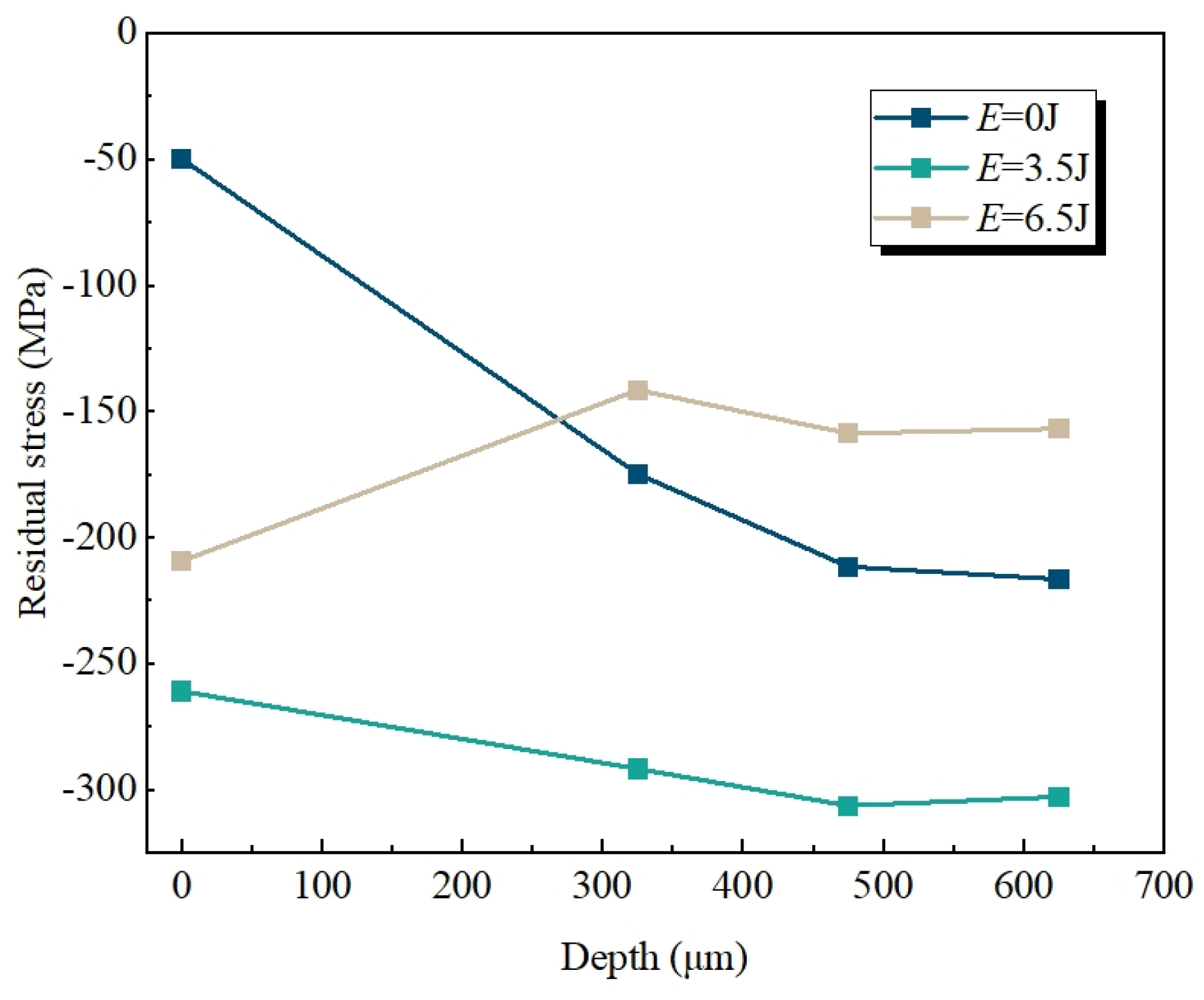
3.2. Residual Stress
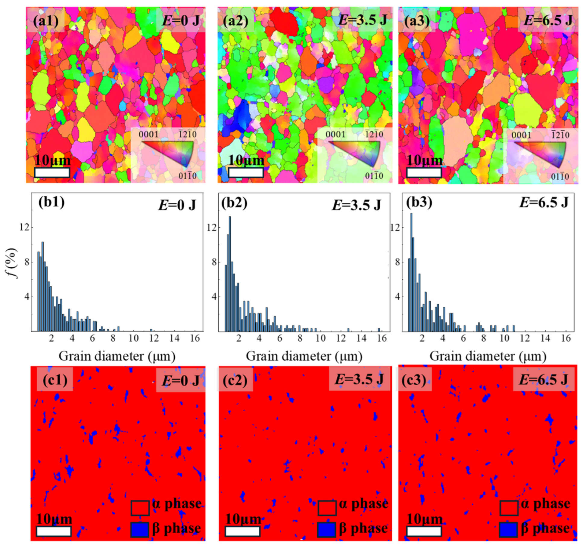
The residual stress along the thickness direction of the TC4 specimen subjected to different energy impact is measured by the micro-X-ray diffraction method. The Auto MATE II X-ray stress analyzer (Pulstec Industrial Co., Ltd, Hamamatsu, Japan) is used with a measurement error of ±14 MPa. Four test points are measured from the surface to a depth of 625 μm. As shown in Figure 4, the residual stress near the surface of the unimpacted TC4 specimen exhibits a slight compressive value that gradually increases with the depth. The residual stress distribution changes significantly with the surface compressive stress increasing to about ~260 MPa and maintaining a high compressive stress level along the depth direction at E = 3.5 J. Beyond the critical pulse energy threshold, the induced residual stress exhibits an inverse relationship with increasing energy. These results demonstrate consistent correlation trends between residual stress evolution and fatigue life behavior. In the studies of LSP in metals, the higher residual stress is typically correlated with enhanced fatigue life [32,33]. However, compared to the unimpacted sample, the specimen with the pulse energy of 6.5 J exhibits a similar fatigue life but with a lower residual stress distribution in our study. It is presumed to be related to the temperature increase during the laser impact process, as will be analyzed in detail in Section 4.2.

3.3. Grain Analysis

In general, the mechanical behavior of materials is greatly related to the microstructure. The representative surface structures of specimens under the pulse energy of 0 J, 3.5 J and 6.5 J are, respectively, illustrated in Figure 5. The IPF plot in Figure 5(a1) shows the grain orientation in the pristine specimen, revealing a relatively random distribution mode with less <01 1 - 0> selective orientation. As the pulse energy increases, the red grains of the <0001> orientation decrease obviously, while the green grains of the < 1 - 2 1 - 0> orientation increase significantly (Figure 5(a2)). When the pulse energy exceeds 3.5 J, the grain density with < 1 - 2 1 - 0> orientation gradually reduces and finally presents a random orientation state again (Figure 5(a3)). For the α-titanium, the < 1 - 2 1 - 0> orientation is the easy slip direction. The optimal laser parameters induce the direction perpendicular to the loading axis, suppressing the dislocation activation and enhancing the fatigue resistance.
The grain size distribution depicted in Figure 5b illustrates that the laser impact induces a pronounced crystallization refinement effect, which is accompanied by a significant increase in the proportion of small grains (d < 2 μm). Grain refinement can impede crack propagation to some extent as well as enhance the fatigue life of the material [34,35]. However, in high-energy impact specimens (E = 6.5 J), the proportion of relatively large grains (d > 7 μm) also increases, leading to a discontinuous grain size distribution that can impact the material’s compatible deformation and load-bearing capacity [36].
Furthermore, the LSP treatment also induces significant phase transformation, which closely corresponds to the mechanical property. As shown in Figure 5c, red regions indicate the α phase while blue regions denote the β phase. They are identified and quantified by collecting Kikuchi bands and the corresponding crystallographic database. The β phase content in the original sample is 4.1% with a relatively uniform distribution. After the laser impact of 3.5 J, the β phase content drops to 2.2%, and simultaneously, the grain size becomes smaller. However, in the sample treated with pulse energy of 6.5 J, the β phase content is about 3.5%, which is accompanied by the formation of coarse phase grains. In titanium alloys, the β phase exhibits lower strength and hardness compared to the α phase, rendering preferential sites for fatigue crack initiation. Therefore, the increase in the α phase content helps to provide better fatigue resistance [37], which is consistent with the fatigue life test results of the samples.

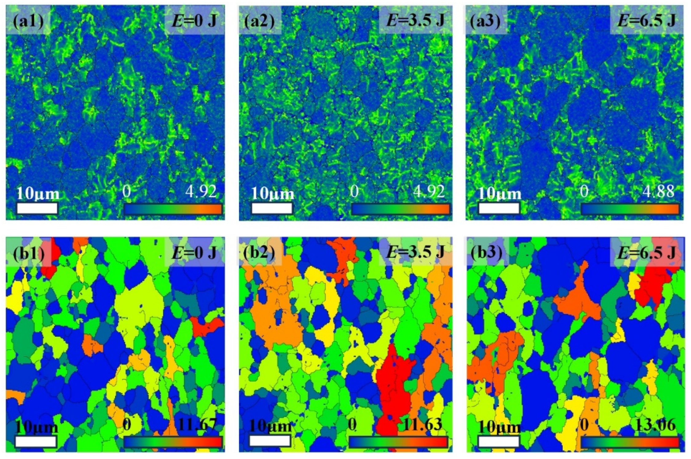
3.4. Plastic Deformation

The Kernel Average Misorientation (KAM) plot displayed in Figure 6a reflects the homogenization degree of plastic deformation within the material. The color transition from blue to red corresponds to progressively increasing plastic deformation. The comparisons indicate that the green and blue colors predominate in both the original sample and the specimen with E = 6.5 J, suggesting a non-uniform distribution and heterogeneous deformation. Combined with Figure 5a, it is evident that the blue regions are predominantly located in the larger grains, which experience reduced plastic deformation under load. In contrast, the plastic deformation distribution in the specimen with E = 3.5 J is more homogeneous.
As shown in Figure 6b, the Grain Orientation Spread (GOS) plot represents the dispersion degree of the grain orientation. The transition from blue to red indicates an increase in material lattice distortion and dislocation density. Most regions of the pristine sample display low GOS values, indicating a relatively homogeneous internal structure of the grains. Meanwhile, the LSP samples, especially under E = 3.5 J, exhibit more regions with elevated GOS values, meaning that more severe plastic deformation occurs. The appropriate increase in dislocation density and plastic deformation caused by LSP can enhance the material’s fatigue life, which is consistent with fatigue research [38].

4. Discussion

4.1. Microstructure Effect

To explore the locations most susceptible to fatigue failure, the stress distribution of models under loading is calculated and compared by the CPFE method. Three models are analyzed, respectively, including the α models with non-uniform grains (Figure 7a) and uniform grains (Figure 7b), and the dual-phase model (Figure 7c). The increase in stress magnitude is represented by the color from blue to red. For the α models, the high stress is mainly distributed at the polycrystalline junction in addition to the fixed boundary. The maximum stresses of the inhomogeneous and the homogeneous grain models are similar with 1012 MPa and 1026 MPa, respectively. The stress difference is not obvious, which can be limited by model size and grain gradient. The β phase has a more significant effect on the internal stress distribution, usually bearing a lower stress and causing a higher stress at the phase boundary, as depicted in Figure 7(c1). The corresponding fatigue life of the three models is analyzed in Figure 8. The different colors from red to blue indicate the increase in fatigue life. The fatigue failure predominantly occurs at grain boundaries and phase interfaces with the maximum stress concentration and the minimum fatigue life. The simulation results are consistent with the fatigue test and microstructure observation of LSP specimens, and they are also a supplement to the fatigue failure analysis by the stress distribution view. However, compared to the real complex microstructures, the simulation models are simplified. Although the simulation models capture the order-of-magnitude agreement with experiments, the numerical discrepancies still persist.

4.2. Temperature Rise Effect

In this study, the fatigue threshold phenomenon and the specially change in microstructure under high-energy impact may be greatly related to the temperature rise effect. It can not only activate α-β phase transformation but also trigger the recrystallization. Upon exceeding a critical laser power density, the lattice temperature rises above the melting point. In the rapid melting process, the solid–liquid interface temperature can increase significantly to above the melting point, causing the superheating of the solid phase material. Similarly, during the rapid solidification, the solid–liquid interface temperature can be cooled well below the melting point, making the liquid phase material become supercooling [39]. Once the phase transition occurs in the superheated solid or supercooled liquid, the solid–liquid interface can move at a very fast rate. The temperature rise during the process is extremely brief, as the laser shock wave has a very short duration [40]:
Δ T = β ρ C v 0 γ τ d τ β ρ C v × P × ε
where β , ρ and C v are denoted as the Taylor coefficient, density, and specific heat capacity, respectively; γ is the impact time; P is the peak pressure of the shock wave, and ε is the strain during the impact. Here, ε is equal to ε ˙ Δ t and Δ t is usually two to three times the pulse width. For the TC4 titanium alloy in this paper, the parameters are listed in Table 2. It can be calculated that the transient temperatures under E = 3.5 J and E = 6.5 J, respectively, rise to 1397 °C and 1769 °C, both exceeding the phase transition temperature and recrystallization temperature. Moreover, the temperature produced by the laser impact of E = 6.5 J is above the melting point (1660 °C).
At elevated temperatures, the residual stresses in TC4 titanium alloys are usually alleviated through thermally activated mechanisms [43,44,45]. The high temperature can promote dislocation nucleation, dislocation movement, grain boundary migration, etc., leading to the partial release of residual stresses. However, due to the extremely short duration of the laser shock, the overall impact of these thermal effects remains limited. Coupled with the compressive stress introduced by the LSP, most of the residual compressive stress can be retained, thus improving the fatigue life. When LSP parameters exceed optimal values, the gradual stress relaxation develops during impact. Additionally, the transient temperature above the melting point can facilitate stress release and redistribution through the recrystallization mechanism [46,47,48].

5. Conclusions

In this paper, the fatigue-strengthening behavior and microscopic mechanism of laser-shocked TC4 titanium alloy have been systematically studied by experiment and CPFE simulation. The results demonstrate that a threshold phenomenon in fatigue life is shown with the increase in pulse energy and the maximum life is increased by 126% at E = 3.5 J. Through the EBSD analysis, the appropriate LSP treatment can introduce the residual stress, reduce the β phase proportion, promote the grain refinement and homogeneous, and thus lead to more uniform plastic deformation. Simultaneously, the < 1 - 2 1 - 0>-texture is activated, and the dislocation nucleation and movement can be limited as the easiest slip direction perpendicular to the loading direction, which helps improve the fatigue performance. Moreover, the stress distribution of different polycrystalline models is calculated by the CPFE method. The stress concentration usually appears at the phase boundary and the grain junction, which also act as the prior fatigue failure points. Notably, the homogeneous α phase microstructure with uniform grain distribution demonstrates peak fatigue resistance and minimal intergranular lifespan variability.
Furthermore, the transient temperature rise effect can be induced by LSP, which affects the residual stress and microstructure evolution. The competition of stress release and stress retention can be expressed under different laser parameters. High temperature can promote the nucleation and evolution of defects, thereby releasing a part of the stress. However, due to the extremely short duration of laser shock and the pressure applied, most of the residual compressive stress and the impacted structure are retained. Meanwhile, the excessive LSP energy leads to transient temperature, surpassing the melting point of materials, probably altering recrystallization microstructure and stress distribution, ultimately degrading fatigue performance.

Author Contributions

Conceptualization, S.Z. and Q.Z.; methodology, Z.Z. and X.Q.; software, S.Z., H.Z. and J.Y.; validation, Z.Z. and Q.Z.; formal analysis, S.Z. and Q.Z.; investigation, S.Z.; resources, X.Q.; data curation, S.Z. and X.Q.; writing—original draft preparation, S.Z.; writing—review and editing, Q.Z.; visualization, S.Z., H.Z. and J.Y.; supervision, Q.Z.; project administration, Q.Z.; funding acquisition, Q.Z. All authors have read and agreed to the published version of the manuscript.

Funding

This work is supported by the National Natural Science Foundation of China (12272120, 12402084).

Data Availability Statement

The original contributions presented in this study are included in the article. Further inquiries can be directed to the corresponding author.

Acknowledgments

The authors would like to express the great gratitude to Wei Guo at Beihang University for the equipment and software supports, as well as the helpful discussions.

Conflicts of Interest

The authors declare no conflict of interest.

References

  1. Nie, X.F.; He, W.F.; Cao, Z.Y.; Song, J.D.; Li, X.; Pang, Z.C.; Yan, X.Y. Experimental study and fatigue life prediction on high cycle fatigue performance of laser-peened TC4 titanium alloy. Mater. Sci. Eng. A 2021, 822, 141658. [Google Scholar] [CrossRef]
  2. Wang, C.; Liu, X.; Huang, H.; Wang, S.; Li, B.; Wang, X.; Deng, H.; Shen, G. FEM-ANN coupling dynamic prediction of residual stresses induced by laser shock peening of TC4 titanium alloy. Opt. Laser Technol. 2024, 179, 111395. [Google Scholar] [CrossRef]
  3. Zhang, S.; Jiang, R.; Wang, R.; Qin, X.; Zhang, Y.; Zhang, W. Mechanical behaviour and subsurface characteristics of Ti-6Al-4V subjected to electropulsing-assisted multiple laser shock processing impacts. Mater. Sci. Eng. A 2025, 920, 147553. [Google Scholar] [CrossRef]
  4. Voisin, T.; Calta, N.P.; Khairallah, S.A.; Forien, J.B.; Balogh, L.; Cunningham, R.W.; Rollett, A.D.; Wang, Y.M. Defects-dictated tensile properties of selective laser melted Ti-6Al-4V. Mater. Des. 2018, 158, 113–126. [Google Scholar] [CrossRef]
  5. Li, Z.C.; Affolter, C. High-cycle fatigue performance of laser powder bed fusion Ti-6Al-4V alloy with Inherent internal defects: A critical literature review. Metals 2024, 14, 972. [Google Scholar] [CrossRef]
  6. Tang, W.; Su, S.; Sun, S.; Liu, S.; Yi, M. Phase-field modeling for predicting three-dimensional fatigue crack initiation and growth under laser shock peening induced residual stress. Int. J. Fatigue 2025, 193, 108786. [Google Scholar] [CrossRef]
  7. Zhang, Y.X.; Guo, W.; Shi, J.X.; Chi, J.X.; Chen, G.X.; Han, G.F.; Zhang, H.Q. Improved rotating bending fatigue performance of laser directed energy deposited Ti6Al4V alloys by laser shock peening. J. Alloys Compd. 2024, 980, 173664. [Google Scholar] [CrossRef]
  8. Phipps, C.R., Jr.; Turner, T.P.; Harrison, R.F.; York, G.W.; Osborne, W.Z.; Anderson, G.K.; Corlis, X.F.; Haynes, L.C.; Steele, H.S.; Spicochi, K.C.; et al. Impulse coupling to targets in vacuum by KrF, HF, and CO2 single-pulse lasers. J. Appl. Phys. 1988, 64, 1083–1096. [Google Scholar] [CrossRef]
  9. Fabbro, R.; Fournier, J.; Ballard, P.; Devaux, D.; Virmont, J. Physical study of laser-produced plasma in confined geometry. J. Appl. Phys. 1990, 68, 775–784. [Google Scholar] [CrossRef]
  10. Hu, W.; Peng, X.; Ding, Y.; Zhu, Z.; Ma, G.; Wang, J.; Ye, Z.; Li, D. The effect of laser shock processing on the microstructures and properties of 2060 Al Li alloys. Surf. Coat. Technol. 2022, 434, 128208. [Google Scholar] [CrossRef]
  11. Attolico, M.A.; Barile, C.; Casavola, C.; Moramarco, V.; Furfari, D.; Busse, D.O. Effects of laser shock peening on surface roughness and residual stress of AA 7050-T7451. J. Mater. Eng. Perform. 2022, 31, 7973–7988. [Google Scholar] [CrossRef]
  12. Hu, X.; Yang, Y.; Zhao, J.; Lu, Y.; Wu, J.; Qiao, H. Surface integrity evolution of a Ni-based single crystal superalloy by laser shock peening. Appl. Surf. Sci. 2021, 6, 100183. [Google Scholar] [CrossRef]
  13. Luo, X.; Xu, Z.; Tian, K.; Wang, Y.; Wang, X.; Wang, K.; Yu, Y.; Ye, C.; Dang, N. Effect of overlap pattern on the residual stress, surface morphology and fatigue properties of Ti-6Al-4V alloy by multiple laser shock peening. Opt. Laser Technol. 2025, 180, 111486. [Google Scholar] [CrossRef]
  14. Zhelnin, M.; Kostina, A.; Vshivkov, A.; Gachegova, E.; Plekhov, O.; Swaroop, S. Fatigue life investigation of notched TC4 specimens subjected to different patterns of laser shock peening. Frat. Integr Strut. 2023, 17, 100–111. [Google Scholar]
  15. Wang, B.; Cheng, L.; Wu, Y.; Ding, J.; Zhang, X. Research on ultra-high cycle fatigue performance and reliability life analysis of TC4 by laser shock peening. J. Phys. Conf. Ser. 2022, 2174, 012037. [Google Scholar] [CrossRef]
  16. Wang, M.Y.; Chen, X.Z.; Dai, F.Z.; Siddiquee, A.N.; Konovalov, S. Effects of different laser shock processes on the surface morphology and roughness of TC4 titanium alloy. J Mater Process Tech. 2024, 325, 118301. [Google Scholar] [CrossRef]
  17. Jiang, Y.; Liu, X.; Wang, Y.; Cui, L.; Ji, G.; Liu, W.; Wang, S. Investigation of residual stress distribution and fatigue of 7050-T7451 alloy hole components with laser shock and ultrasonic extrusion. Metals 2024, 14, 597. [Google Scholar] [CrossRef]
  18. Liu, Q.; Chu, S.; Zhang, X.; Wang, Y.; Zhao, H.; Zhou, B.; Wang, H.; Wu, G.; Mao, B. Laser shock processing of titanium alloys: A critical review on the microstructure evolution and enhanced engineering performance. J. Mater. Sci. Technol. 2025, 209, 262–291. [Google Scholar] [CrossRef]
  19. Zhang, H.P.; Cai, Z.Y.; Guo, W.; Zhang, H.Q.; Yan, J.F.; He, G.Z.; Zhang, Y.X.; Sun, R.J.; Che, Z.G. Experimental and numerical studies of fatigue behavior of Ti6Al4V alloy treated by laser shock peening. Surf. Coat. Technol. 2022, 441, 128524. [Google Scholar] [CrossRef]
  20. Wang, L.; Zhou, L.; Liu, L.; He, W.; Pan, X.; Nie, X.; Luo, S. Fatigue strength improvement in Ti-6Al-4V subjected to foreign object damage by combined treatment of laser shock peening and shot peening. Int. J. Fatigue 2022, 155, 106581. [Google Scholar] [CrossRef]
  21. Wang, Q.; Ma, Y.; Fu, X.; Liu, M.; Cao, Z.; Gai, P.; Zhou, W. Numerical simulation study of combined shot peening and laser shock peening on surface integrity of Ti-6Al-4V titanium alloy. Surf. Coat. Technol. 2024, 487, 130997. [Google Scholar] [CrossRef]
  22. Wang, X.; Zhang, L.; Na, S. Effect of manganese on grain morphology and microstructure of Ti-6Al-4V alloy by laser wire deposition. J. Mater. Res. Technol. 2024, 32, 1141–1151. [Google Scholar] [CrossRef]
  23. Hu, W.; Yi, M. Predicting tensile behavior and fatigue life of laser shock peened titanium alloy by crystal plasticity model. Int. J. Fatigue 2024, 187, 108476. [Google Scholar] [CrossRef]
  24. Ren, J.; Wang, Q.; Zhang, B.; Yang, D.; Lu, X.; Zhang, X.; Zhang, X.; Hu, J. Influence of microstructure on fatigue crack growth behavior of Ti-6Al-3Nb-2Zr-1Mo alloy: Bimodal vs. lamellar structures. Intermetallics 2021, 130, 107058. [Google Scholar] [CrossRef]
  25. Ouyang, W.; Zhang, L.; Wu, H.C.; Wu, D.; Zhang, S.W.; Qin, X.; Jiang, S.L.; Li, S.J.; Zhang, W.W.; Sheng, L.Y. Optimized mechanical properties of the hot forged Ti-6Al-4V alloy by regulating multiscale microstructure via laser shock peening. Int. J. Mach. Tools Manuf. 2024, 201, 104192. [Google Scholar] [CrossRef]
  26. Zeng, L.; Lei, L.; Yang, J.; Luo, X.; Zhang, G. Microstructure-dependent local fatigue cracking resistance of bimodal Ti-6Al-4V alloys. Adv. Eng. Mater. 2018, 20, 1700702. [Google Scholar] [CrossRef]
  27. Guo, P.; Zhao, Y.; Zeng, W.; Liu, J. Effect of microstructure on the fatigue crack propagation behavior of TC4-DT titanium alloy. J. Mater. Eng. Perform. 2015, 24, 1865–1870. [Google Scholar] [CrossRef]
  28. Wu, D.; Liu, L.; Zhang, L.; Wang, W.; Zhou, K. Tensile deformation mechanism and micro-void nucleation of Ti-55531 alloy with bimodal microstructure. J. Mater. Res. Technol. 2020, 9, 15442–15453. [Google Scholar] [CrossRef]
  29. ASTM E466-21; Standard Practice for Conducting Force Controlled Constant Amplitude Axial Fatigue Tests of Metallic Materials. ASTM International: West Conshohocken, PA, USA, 2021.
  30. Taylor, G.I. Plastic Deformation of Metals. J. Inst. Met. 1938, 62, 307–324. [Google Scholar]
  31. Kapoor, K.; Ravi, P.; Noraas, R.; Park, J.; Venkatesh, V.; Sangid, M. Modeling Ti-6Al-4V using crystal plasticity, calibrated with multi-scale experiments, tounderstand the effect of the orientation and morphology of the alpha and beta phases on time dependent cyclic loading. J. Mech. Phys. Solids. 2021, 146, 104192. [Google Scholar] [CrossRef]
  32. Wang, B.; Cheng, L.; Li, D.C. Study on very high cycle fatigue properties of forged TC4 titanium alloy treated by laser shock peening under three-point bending. Int. J. Fatigue 2022, 156, 106668. [Google Scholar] [CrossRef]
  33. Ermakova, A.; Razavi, N.; Cabeza, S.; Gadalinska, E.; Reid, M.; Paradowska, A.; Ganguly, S.; Berto, F.; Mehmanparast, A. The effect of surface treatment and orientation on fatigue crack growth rate and residual stress distribution of wire arc additively manufactured low carbon steel components. J. Mater. Res. Technol. 2023, 24, 2988–3004. [Google Scholar] [CrossRef]
  34. Luo, J.; Tang, W.; Cui, S. The effect of laser shock peening on the microstructure and wear resistance of micro-arc oxidation coatings on TC4 alloy. J. Mater. Res. Technol. 2023, 26, 5851–5859. [Google Scholar] [CrossRef]
  35. Xiao, J.F.; Jing, Y.D.; Esmaeilzadeh, R.; Cayron, C.; Logé, R.E. Microstructure and texture evolution in laser shock peened martensitic NiTi shape memory alloy. Mater. Des. 2025, 249, 113555. [Google Scholar] [CrossRef]
  36. Ren, X.D.; Zhou, W.F.; Liu, F.F.; Ren, Y.P.; Yuan, S.Q.; Ren, N.F.; Xu, S.D.; Yang, T. Microstructure evolution and grain refinement of Ti-6Al-4V alloy by laser shock processing. Appl. Surf. Sci. 2016, 363, 44–49. [Google Scholar] [CrossRef]
  37. Matsumoto, H.; Yoneda, H.; Sato, K.; Kurosu, S.; Maire, E.; Fabregue, D.; Konno, T.J.; Chiba, A. Room-temperature ductility of Ti-6Al-4V alloy with α′ martensite microstructure. Mater. Sci. Eng. A 2011, 28, 1512–1520. [Google Scholar] [CrossRef]
  38. Ye, C.; Telang, A.; Gill, A.; Suslov, S.; Yaakov, I.; Zweiacher, K.; Wiezorek, M.K.; Zhou, Z.; Qian, D.; Mannava, S.R.; et al. Gradient nanostructure and residual stresses induced by Ultrasonic Nano-crystal Surface Modification in 304 austenitic stainless steel for high strength and high ductility. Mater. Sci. Eng. A 2014, 613, 274–288. [Google Scholar] [CrossRef]
  39. Li, N.; Wang, Y.D.; Lin, R.P.; Sun, X.; Liaw, P.K.; Wu, G.L.; Wang, L.; Cai, H.N. Localized amorphism after high-strain-rate deformation in TWIP steel. Acta Mater. 2011, 59, 6369–6377. [Google Scholar] [CrossRef]
  40. Pan, X.; Wang, X.; Tian, Z.; He, W.; Shi, X.; Chen, P.; Zhou, L. Effect of dynamic recrystallization on texture orientation and grain refinement of Ti6Al4V titanium alloy subjected to laser shock peening. J. Alloys Compd. 2021, 850, 156672. [Google Scholar] [CrossRef]
  41. Lu, J.Z.; Luo, K.Y.; Zhang, Y.K.; Cui, C.Y.; Sun, G.F.; Zhou, J.Z.; Zhang, L.; You, J.; Chen, K.M.; Zhong, J.W. Grain refinement of LY2 aluminum alloy induced by ultra-high plastic strain during multiple laser shock processing impacts. Acta Mater. 2010, 58, 3984–3994. [Google Scholar] [CrossRef]
  42. Yang, Y.; Zhang, H.; Qiao, H.C. Microstructure characteristics and formation mechanism of TC17 titanium alloy induced by laser shock processing. J. Alloys Compd. 2017, 722, 509–516. [Google Scholar] [CrossRef]
  43. Zaeh, M.F.; Branner, G. Investigations on residual stresses and deformations in selective laser melting. Prod. Eng. Res. Devel. 2010, 4, 35–45. [Google Scholar] [CrossRef]
  44. Wu, J.; Wang, L.; An, X. Numerical analysis of residual stress evolution of AlSi10Mg manufactured by selective laser melting. Optik 2017, 137, 65–78. [Google Scholar] [CrossRef]
  45. Zhang, X.; Kang, J.; Rong, Y.; Wu, P.; Feng, T. Effect of scanning routes on the stress and deformation of overhang structures fabricated by SLM. Materials 2018, 12, 47. [Google Scholar] [CrossRef]
  46. Aboulkhair, N.T.; Simonelli, M.; Parry, L.; Ashcroft, I.; Tuck, C.; Hague, R. 3D printing of aluminium alloys: Additive manufacturing of aluminium alloys using selective laser melting. Prog. Mater. Sci. 2019, 106, 100578. [Google Scholar] [CrossRef]
  47. Guo, W.; Sun, R.; Song, B.; Zhu, Y.; Li, F.; Che, Z.; Li, B.; Guo, C.; Liu, L.; Peng, P. Laser shock peening of laser additive manufactured Ti6Al4V titanium alloy. Surf. Coat. Technol. 2018, 349, 503–510. [Google Scholar] [CrossRef]
  48. Dai, S.; Zhu, Y.; Huang, Z. Microstructure evolution and strengthening mechanisms of pure titanium with nano-structured surface obtained by high energy shot peening. Vacuum 2016, 125, 215–221. [Google Scholar] [CrossRef]
Figure 1. Experimental design: (a) laser impact principle, (b) specimen dimension, (c) spot path; (d) fatigue equipment.
Metals 15 00453 g001
Figure 2. Polycrystalline finite element models: (a) boundary conditions, (b) inhomogeneous α phase, (c) homogeneous α phase, (d) dual-phase structure.
Metals 15 00453 g002
Figure 3. Fatigue life and typical fracture topography of TC4 plate under different pulse energy.
Metals 15 00453 g003
Figure 4. Residual stress distribution along the depth.
Metals 15 00453 g004
Figure 5. Crystal structure under different pulse energy: (a) IPF, (b) particle size frequency distribution, (c) phase content distribution.
Metals 15 00453 g005
Figure 6. Plastic deformation of crystal under different pulse energy: (a) KAM, (b) GOS.
Metals 15 00453 g006
Figure 7. Stress cloud: (a1) inhomogeneous α model, (b1) homogeneous α model, (c1) dual-phase model. The corresponding maximum stress at grain and phase boundary is expressed in (a2c2).
Metals 15 00453 g007
Figure 8. Fatigue life plots: (a1) inhomogeneous α model, (b1) homogeneous α model, (c1) dual-phase model. The corresponding minimum fatigue life point is magnified in (a2c2).
Metals 15 00453 g008
Table 1. Parameters of the intrinsic plasticity model for TC4 crystal. Adapted from Ref. [31].
Parameterα Phaseβ Phase
C11/MPa162,40013,500
C12/MPa920011,300
C44/MPa690054,900
C13/MPa180,700
C33/MPa49,700
τ0/MPaBasal420333
Prism420
Pyramidal490
τs/MPaBasal462366
Prism407
Pyramidal539
h0/MPaBasal631.2100
Prism436.2
Pyramidal436.2
γ0.0010.001
n1515
Table 2. Parameters related to temperature rise effect of TC4 titanium alloy. Adapted from Refs. [41,42].
ParametersValue
β 0.9
ε ˙ /s−1107
Δ t /ns50
ρ /g·cm−34.40
C v /kJ·kg−1·°C−10.565
P /GPaE = 3.5 J7.717
E = 6.5 J9.775
Disclaimer/Publisher’s Note: The statements, opinions and data contained in all publications are solely those of the individual author(s) and contributor(s) and not of MDPI and/or the editor(s). MDPI and/or the editor(s) disclaim responsibility for any injury to people or property resulting from any ideas, methods, instructions or products referred to in the content.

