Article

Research on the Microstructure and Properties of QT400-18 Laser Cladding Remanufacturing

1
School of Materials Science and Engineering, Taiyuan University of Technology, Taiyuan 030024, China
2
CRRC Tangshan Locomotive and Rolling Stock Co., Ltd., Tangshan 064000, China
*
Author to whom correspondence should be addressed.
Metals 2025, 15(3), 312; https://doi.org/10.3390/met15030312
Submission received: 24 January 2025 / Revised: 8 March 2025 / Accepted: 11 March 2025 / Published: 13 March 2025
(This article belongs to the Special Issue Development of Metallic Material Laser Additive Manufacturing)

Abstract

:
To address the failure issue of local wear in QT400-18 transition shafts used in high-speed trains, laser cladding remanufacturing of a ductile cast iron surface was carried out using 45 wt.%Fe + 55 wt.% Inconel625 powder. The phase composition, microhardness, interfacial bonding strength, and wear resistance of the cladding layer were analyzed. The results show that the cladding layer is primarily composed of a γ (Ni, Fe) solid solution and a small amount of eutectic carbides. The microstructure of the cladding layer forms columnar dendrites, cellular dendrites, and equiaxed crystals from bottom to top. The microstructure of the single-layer, single-pass interface consists of ferrite, acicular martensite, and ledeburite, while the multi-layer, multi-pass interface consists of ferrite, granular pearlite, and discontinuous ledeburite. The average microhardness of the single-layer, single-pass cladding layer is approximately 350 HV0.5, and the hardness of the fine-grained and coarse-grained regions of the multi-layer, multi-pass cladding layer is approximately 330 HV0.5 and 250 HV0.5, respectively. The interfacial bonding strength reaches 96.5% of the base material strength. The wear mechanism of the cladding layer is mainly mild abrasive wear, with significantly better wear resistance than the base material.

1. Introduction

Ductile cast iron transition shafts are widely used in high-speed rail, intercity rail vehicles, and subway [1], as they are the key components subjected to significant loads and frequent motion. As the service life of these vehicles increases, the inner walls of the transition shafts may experience localized wear, leading to failure. If the entire transition shaft structure is scrapped due to localized wear of the inner walls, not only does the dismantling and crushing of the scrapped components consume a significant amount of energy, but the remanufacturing of the cast iron parts also requires considerable energy consumption. The emissions from exhaust gases and slag during this process can cause secondary environmental pollution, while also wasting substantial labor and time costs. Therefore, developing fast and effective remanufacturing and repair techniques for ductile cast iron transition shaft structures is of great significance.
Compared to other metallic materials, the repair of cast iron is more challenging. First, welding can easily lead to the formation of white cast iron structures, which significantly increase the hardness of the weld metal, making it difficult to machine. Secondly, cracks may occur, including weld cracks, cracking of the welded component, and delamination at the interface between the weld metal and the base material. Furthermore, due to the high cooling rate after welding, porosity is likely to develop. More importantly, because cast iron contains elements that promote graphite degeneration, the tendency for white cast iron formation and cracking in the welded area is higher, and the repaired part still carries a risk of deformation and cracking after the repair is completed. Traditional repair methods for ductile cast iron components include stick electrode arc welding, CO2 gas shielded welding, oxyacetylene welding, brazing, electroslag welding, and plasma spraying [2,3,4]. Among these, arc welding is the most widely used, especially for repairing cracks and other volumetric defects in cast iron. Alireza Sadeghi [5] used manual arc welding to repair the surface of gray cast iron. Three kinds of welding electrodes were selected in the study: a nickel electrode, carbon steel electrode, and hardening electrode. The weldability and microstructure differences were compared. The results showed that a nickel electrode can reduce the formation of bad phases, and the wear resistance of all the welded joints is better than that of the substrate. The carbon steel electrode showed good corrosion resistance in a zero-resistance ammeter (ZRA) test. Arabi Jeshwaghani [6] and others prepared a nickel-based alloy coating on ductile cast iron by manual arc welding to enhance its wear resistance. Mahdi Mahmoudiniya [7] used arc wire additive manufacturing (WAAM) technology to deposit nickel-based alloys onto malleable cast iron substrates, and prepared a bimetallic structure of nickel–45% iron alloy and malleable cast iron. The yield strength and tensile strength of the deposited alloy were lower than those of the cast iron substrate.
Laser cladding additive remanufacturing technology builds or modifies parts with complex geometries through continuous material deposition. It allows for the rapid formation and repair of any missing or damaged parts. Compared to traditional repair methods (such as arc welding), laser cladding has the advantage of lower heat input, which results in a smaller heat-affected zone, making it more suitable for the repair of structural members [8,9,10,11]. Currently, many researchers have made significant progress in using laser cladding additive remanufacturing technology to repair Fe-based parts and improve their surface properties. Liu et al. [12] achieved a nickel-based alloy coating on ductile cast iron through laser cladding. The results indicated that the thermal influence during the multi-layer laser cladding process helps reduce the width of the high microhardness zone and improves the mechanical properties. Yongjian L [13] used a nickel–copper alloy as the filling material to remanufacture malleable cast iron by laser cladding, and designed different simulated grooves. The results showed that a variety of microstructures are formed during the laser remanufacturing process, and the circular groove and cross-cladding processes are helpful for reducing the residual stress. After multiple thermal cycles, the microhardness decreased significantly, but the tensile strength of the final sample was 502 MPa, at least equivalent to that of the substrate. Arias González et al. [14] used laser cladding to obtain a nickel-based alloy coating on ductile cast iron, which showed a good combination of hardness and toughness. Marco Mazzarisi [15] studied the thermal behavior of different deposition strategies using the Laser Metal Deposition (LMD) process and their impact on the microstructure and mechanical properties. By using an infrared thermography system to monitor the temperature field in real-time during the multi-layer deposition of nickel-based superalloys, the experiment showed that a 200 W unidirectional filling strategy, due to its uniform heat input and stable thermal gradient, significantly reduced cracks and porosity, making it suitable for high-precision repairs and the manufacturing of complex components. Mohammad Rezayat [16] studied the effect of the transverse laser cladding process on the corrosion performance of Inconel 625 coatings. By applying different laser powers (150 W, 200 W, and 300 W) to fabricate Inconel 625 coatings on an Inconel 738 substrate, the study found that a moderate power (200 W) reduced defects and promoted the enrichment of Mo/Cr, forming a stable passive layer, which exhibited optimal pitting and uniform corrosion resistance. In contrast, a high power (300 W) and low power (150 W) led to passive layer failure due to structural defects or element oxidation, which exacerbated localized corrosion. Marco Latte studied [17] the use of a laser line scanner to assess the key performance indicators (KPIs) for monitoring the geometrical characteristics and detecting potential subsurface defects during the Laser Metal Deposition (LMD) process. The author developed a method that combines optical monitoring with a data-driven model (M2P) to evaluate the critical factors, such as the pass height, overlap, and contact angle. This approach provides a valuable tool for the real-time monitoring and quality control of the LMD process, reducing the need for costly post-process inspections. Ouyang M et al. [18] used laser cladding additive remanufacturing to repair QT500-7 cast iron and designed a new austenitic Fe-14Ni-19Cr material. The study showed that this material effectively suppresses the formation of defects, such as large brittle phases and cracks. The microhardness of the cladding layer steadily increased, from approximately 200 HV0.2 in the base material to around 257 HV0.2. The laser-cladded samples exhibited mechanical properties comparable to those of the QT500-7 base material, with a tensile strength of 490 MPa, yield strength of 401 MPa, and an elongation of 7.7%.
In the laser cladding remanufacturing process, nickel-based alloys are commonly used to repair ductile cast iron. However, the high cost of nickel-based alloys and the significant color difference between the cladding layer and the substrate after cladding are major issues. Iron-based alloys are sometimes used as cladding and welding materials, but after cladding or welding, a large amount of cooling structures and martensitic structures often form in the semi-melted zone, which can lead to cracking and brittle behavior. Pengcong, Y et al. [19] used a continuous-wave semiconductor laser to fabricate an iron-based coating on the surface of ductile cast iron. The experiment found that when the laser power was high (1600 W), multiple solidification cracks were observed near the interface of the coating. Weng, Z et al. [20] used laser cladding to simulate the pit remanufacturing of ductile cast iron and found that when the pit depth was less than 10 mm and the bevel angle was larger, a through crack appeared at the interface of the remanufactured layer. As a result, the application of iron-based alloy powders has been significantly limited. During the cladding process, the Ni elements effectively prevent the diffusion of carbon and reduce the tendency for cold structures in the semi-melted zone. As a result, iron–nickel-based alloys are commonly used as the filler materials for welding ductile cast iron. However, the mechanical properties of iron–nickel-based alloys are often inadequate for the remanufacturing of high-strength ductile cast iron. In contrast, Inconel 625 alloy, with its higher Cr content, exhibits significantly better mechanical properties compared to conventional iron–nickel-based alloys [21]. Therefore, this study controls the mass ratio of the Fe powder and Inconel 625 alloy powder to develop a new iron-based alloy powder material with excellent performance. Using QT400-18 ductile cast iron as the substrate, this study investigates the microstructure, mechanical properties, and wear resistance of the interface and cladding layer, providing a theoretical reference and technical support for the surface repair of ductile cast iron components in high-speed train couplings.

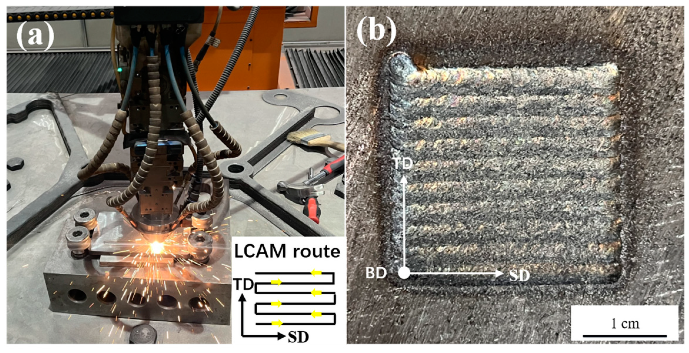
2. Materials and Methods

The base material used in the experiment is QT400-18 ductile cast iron (CRRC Tangshan Locomotive and Rolling Stock Co., Ltd., Tangshan, China). The selected base material is from a large crankshaft used in a high-speed train, with the dimensions of the substrate being 160 ± 2 mm in length, 100 ± 1 mm in width, and 8 ± 0.5 mm in thickness. The material has a tensile strength σb ≥ 400 MPa, a yield strength σ0.2 ≥ 250 MPa, and a hardness range of 150–180 HV0.5. The microstructure of the base material is primarily composed of ferrite. Its chemical composition is shown in Table 1 [22].
In this study, we initially simulated and calculated the thermophysical properties of Fe + Inconel 625 alloy powders with different mass ratios using Jmatpro software (Version 7.0). We found that when the Inconel 625 content reached 60%, the expansion coefficients in both the low- and high-temperature ranges were relatively optimal. However, when the mass fraction of Inconel 625 alloy exceeded 70%, both the tensile strength and hardness decreased significantly. Additionally, we observed that when the mass fraction of Inconel 625 alloy was lower than 50%, severe white cast formation occurred at the interface. Ultimately, we found that the alloy powder with a composition of 45 wt.% Fe + 55 wt.% Inconel 625 exhibited the best interface conditions and optimal performance for the cladding layer. Therefore, in the subsequent research, we prepared 45 wt.% Fe + 55 wt.% Inconel 625 alloy powder with a particle size range of 53–105 μm as the cladding material for this study. The powder has a high spherical shape and good flowability. The chemical composition of the powder is shown in Table 2 [23]. Prior to the experiment, the powder was mechanically mixed and dried in a vacuum drying oven at 120 °C for 60 min.
A high-power disk laser, TruDisk6002 (TRUMPF Group, Ditzingen, Germany), paired with a KUKA robotic arm (KUKA AG, Augsburg, Germany), was used for the experiment, employing a coaxial powder-feeding method. Both the molten pool protection gas and the powder-feeding gas were high-purity argon. During the forming process, the laser head was tilted 6–8° off-axis to reduce the damage caused by laser reflection to the laser system. The direction of the tilt was aligned with the forming direction to ensure the geometric symmetry of the cladding layer. The laser head was positioned 13 mm above the workpiece surface. During the cladding process, the spot diameter output of the laser head was kept at 3.5 mm, and the number of passes of the multi-layer and multi-pass processing layer were 3 layers and 10 passes. The scanning strategy adopted bow-shaped path forming, and the overlap rate between the passes was 50%. In the process of multi-layer and multi-pass forming, the upper and lower layers stayed for 5–10 s, so as to avoid serious heat accumulation during the forming process. According to the welding standard of cast iron, the surface of the substrate is polished before cladding, and then cleaned with acetone to ensure that there is no oxide skin or oil on the surface. The process parameters for the base material were as follows: laser power: 1600 W; scanning speed: 240 mm·min−1; and powder-feeding rate: 7 g·min−1. Figure 1a shows an on-site photograph of the laser cladding additive remanufacturing process. Figure 1b presents a multi-layer multi-pass laser cladding remanufactured product. In the figure, SD represents the scanning direction, BD denotes the build direction of the laser cladding additive remanufacturing, and TD refers to the transverse direction, which is perpendicular to the build direction (BD) and orthogonal to the scanning direction (SD).
After the experiment, the samples were prepared using wire electrical discharge machining. The sample surfaces were polished step by step with 400#–1200# sandpaper, followed by mechanical polishing. A 4% nitric alcohol solution was used to etch the base material and interface regions, with an etching time of 6–7 s. Aqua regia was used to etch the cladding layer, with an etching time of 120 s. The microstructure of the sample cross-section was observed using an optical microscope and scanning electron microscope (SEM) equipped with an energy-dispersive spectroscopy (EDS) analysis system. Elemental analysis was conducted using energy-dispersive X-ray spectroscopy (EDS). Phase identification in the cross-section perpendicular to the cladding direction and the top surface parallel to the cladding direction of the multi-layer, multi-pass cladding layer was evaluated using a D8 DISCOVER X-ray diffractometer (XRD) (Bruker, Bremen, Germany). The scanning angle ranged from 20° to 100°, with a scanning speed of 2°/min. A hardness test was conducted using a DSZF-1 Vickers hardness tester (Shangcai Testing Machine Co., Ltd., Shanghai, China) under a load of 500 g, with a dwell time of 15 s. The interval between adjacent test points was 50 μm. A universal tensile testing machine was used to carry out the tensile–shear test on the sample. The forming layer with a height of more than 3mm was cladded by laser cladding (3 layers and 10 passes) on the plate. The surface of the cladding layer was polished by a grinding machine, and the tensile sample was prepared by wire cutting. The preparation size and shape of the sample are shown in Figure 2. The tensile–shear test referred to GB/T 6396-2008 [24]. The wear resistance of the substrate and cladding layer was tested using a UMT-2 tribo-tester (Bruker, Billerica, Massachusetts). The friction and wear test surfaces were the substrate surface and the top surface of the multi-layer multi-pass cladding specimen parallel to the cladding direction. Before the test, the worn surface was polished step by step with 400#–1200# sandpaper and then polished to a mirror finish. A 4 mm diameter Si3N4 ceramic ball was used as the friction pairs, with a load of 1N applied and reciprocating motion at a frequency of 5Hz on the sample. The wear distance was set to 4 mm. The friction and wear test duration was set to 30 min. A white-light interferometer (Wyko NT1100, Bruker Corporation, Billerica, MA, USA) was used to observe the three-dimensional wear scar morphology of the substrate and the multi-layer multi-pass cladding layer, and to calculate the wear volume. The objective magnification was 2.5×, with a scanning range of 2.5 mm × 3.5 mm.

3. Results and Discussion

3.1. Microstructure of the Cladding Layer

Figure 3a–d show the grain morphology of the cross-section of the single-layer single-pass cladding layer. As shown in Figure 3a, no significant cracks or porosity defects are observable within the cladding layer. The black spots in the images represent graphite nodules that floated up from the base material. The interface between the cladding layer and the base material exhibits a wavy and irregular shape. This is due to the high and concentrated energy of the laser cladding process, which melts the surface of the base material upon contact. The molten base material undergoes a convective mass transfer within the molten pool, diffusing and diluting the cladding layer. A distinct boundary can be observed between the bottom of the cladding layer and the center of the molten pool in terms of the microstructural morphology. The shape of this boundary corresponds closely to the temperature gradient distribution. Below the boundary, coarse dendrites grow from the interface, as shown in Figure 3c. Their growth direction points toward the center of the molten pool. This occurs because the cooling rate near the base material is relatively slow, allowing the grains to grow for a longer period and leading to the formation of coarse dendrites. The concentrated heating from the laser beam and the thermal conduction create a significant temperature gradient in the vertical direction, which promotes grain growth along the direction of the heat flow. Above the boundary, near the center of the molten pool, cellular dendrites and equiaxed crystals form, as shown in Figure 3d,e. This is because, during the laser cladding remanufacturing process, the concentrated heating of the laser beam results in a higher temperature and slower cooling rate at the center of the molten pool. This allows the grains more time to grow uniformly, leading to the formation of equiaxed crystals. In the peripheral or localized areas of the molten pool, a larger temperature gradient and faster cooling rate promote rapid nucleation and growth along the dendritic directions, resulting in cellular dendrites.
Figure 4a–e show the grain morphology of the cross-section of the multi-layer multi-pass cladding samples. The cladding layer exhibits a transition in grain morphology from the bottom to the top, changing sequentially from dendrites, to cellular dendrites + equiaxed crystals, and back to dendrites. Two distinct regions can be observed in the multi-layer multi-pass cladding layer: a fine-grained region and a coarse-grained region. The fine-grained region primarily forms at the bottom of the cladding layer, with a grain structure similar to that of the single-layer single-pass cladding layer. Starting from the second layer, coarse dendrites begin to form, as shown in Figure 4e. This occurs because when the second layer begins to form, the first layer still retains a very high temperature. Consequently, due to the low undercooling and cooling rate, coarse dendritic crystals are formed.
In the XRD pattern shown in Figure 5, the following diffraction peaks are marked: (111), (200), (220), (311), and (222). These peaks are characteristic of a face-centered cubic (FCC) crystal structure and correspond to the γ (Ni, Fe) phase. This indicates that the primary phase of the cladding layer is a γ (Ni, Fe) solid solution; a structure formed by Ni and Fe and further strengthened by the solid solution of elements, such as Cr, Mo, and Nb. The XRD patterns for F1 (perpendicular to the cladding layer) and F2 (parallel to the cladding direction) show significant differences in intensity: in the F2 direction, the (111) and (200) peaks are much stronger than in the other directions. This suggests a pronounced preferred orientation of the grains along the cooling direction of the molten pool ([111] crystal direction) during the laser cladding process. This preferred orientation is typically consistent with the rapid solidification characteristics and thermal gradient direction of laser cladding, indicating that columnar dendrites grow along the [111] direction. No prominent carbide peaks are observable in the XRD pattern, which may be attributed to their low content or fine, dispersed distribution, making them less detectable by XRD. The presence of these carbides significantly contributes to the hardness and wear resistance of the cladding layer.
The EDS surface scan results of the multi-layer, multi-pass cladding layer are shown in Figure 5b. It can be seen that the distribution of the Fe and Ni elements is relatively uniform, while the Nb, Mo, and Cr elements exhibit some degree of segregation. This is due to the extremely rapid heating process during the laser cladding process. The laser beam locally heats the cladding powder material, and the temperature of the melt pool can reach thousands of degrees instantly. Due to the high temperature gradient and local heating by the laser beam, the material in the melt pool undergoes a very short liquid phase and then rapidly cools into a solid state. In the melt pool, due to the extremely short heating time and high temperature, many elements (especially those with lower solubility, such as Nb and Mo) quickly dissolve into a liquid phase, forming an alloyed liquid melt pool. Because of the localized nature of the laser heating, the temperature at the center of the melt pool is typically higher, while the temperature at the edges of the melt pool and the base material is lower. Therefore, elements with a high solubility (such as Fe and Ni) may dissolve in the center of the melt pool, while elements with a low solubility (such as Nb, Mo, and Cr) tend to segregate at the edges of the melt pool or during cooling. The rapid change in the cooling rate causes a sharp change in solubility. Elements with a higher solubility (such as Fe and Ni) will be distributed more uniformly during cooling, while elements with a lower solubility (such as Nb, Mo, and Cr) will segregate during cooling, forming enriched areas or precipitated phases. During cooling, the diffusion rate of these elements is also affected by the temperature gradient, making the segregation phenomenon more prominent. Mo and Cr typically segregate to the areas of the melt pool that cool more slowly, forming local Mo-rich or Cr-rich regions. These enriched regions may lead to the precipitation of hard phases in the cladding layer, thereby increasing its hardness and wear resistance. As shown in the figure, Mo and Cr are distributed relatively locally, indicating that they may have segregated in the melt pool and formed strengthening phases. During the laser cladding process, the distribution of carbon and the formation of carbides are significantly influenced by temperature changes and element diffusion. In the high-temperature regions of the melt pool, carbon may react with alloy elements (such as Cr, Mo, and Ni) to form carbides (such as Cr3C2, Mo2C, etc.). These carbides have a high hardness and good wear resistance. Due to the localized heating of the laser, high temperatures in certain areas may lead to carbide formation, while regions with faster cooling rates may promote the rapid solidification of these carbides, further enhancing the hardness of the cladding layer. As the cooling rate increases, carbides may precipitate during the cooling process. The precipitation of these carbides not only affects the hardness of the cladding layer but also enhances its wear resistance. Particularly, the precipitation of carbides on the material’s surface can effectively improve the ability to resist friction and impact, enhancing the wear performance of the surface [25].

3.2. Microstructure of the Partially Melted Zone and Heat-Affected Zone

Figure 6a,b show the microstructure of the interface region in the single-layer single-pass cladding layer. As shown in Figure 6a, the primary microstructure of the partially melted zone (PMZ) includes acicular martensite and ledeburite. During the cladding process, the PMZ undergoes rapid melting, causing the dissolution of graphite nodules and the diffusion of carbon. Some graphite nodules completely dissolve, forming carbon-rich regions in their original locations, which solidify into ledeburite during rapid cooling. In regions farther from the graphite nodules, the carbon content increases due to diffusion, leading to the formation of martensite during rapid solidification. For the graphite nodules that do not completely dissolve, a typical “double-shell” structure forms around them, with an inner layer of martensite and an outer layer of ledeburite, as shown in Figure 6b. The formation of the double-shell structure is mainly due to two reasons: First, during the heating phase, the carbon concentration near the graphite nodules is relatively high. During cooling, the graphite nodules act as nucleation cores and adsorb carbon atoms, resulting in a carbon-depleted region around the nodules, forming martensite. Second, the graphite nodules act as a heat reservoir during cooling, slowing down the cooling rate of the surrounding area, which leads to the formation of an outer ledeburite layer. The elemental EDS line-scan data from the region near the graphite nodule, as shown in Figure 7, confirm that the area near a graphite nodule is relatively carbon-depleted compared to the region where ledeburite forms.
Figure 8 illustrates the microstructure of the interface region in the multi-layer multi-pass cladding samples. As shown in Figure 8a, compared to the single-layer single-pass cladding samples, the ledeburite region in the partially melted zone (PMZ) is relatively reduced and distributed discontinuously, appearing in an arc-like pattern around the graphite nodules. This is because, in the multi-layer multi-pass laser cladding process, the subsequent laser cladding pass partially remelts the previous pass, causing the further diffusion and redistribution of the carbon in the previous PMZ, which reduces the carbon-rich regions. For the graphite nodules that do not completely dissolve, a “double-shell” structure forms around them, different from that in the single-layer single-pass cladding samples. As shown in Figure 8b, the inner layer is ferrite, while the outer layer is ledeburite. This difference arises because the subsequent laser cladding pass preheats the region during the previous cladding pass, extending the solidification time of the molten pool. This allows the carbon atoms around the graphite nodules more time to be absorbed by the nodules, resulting in a carbon-depleted area around them and a lower cooling rate. The ledeburite consists of proeutectic cementite and granular pearlite distributed within it, as shown in Figure 8c. The presence of pearlite indicates that the temperature in this region during the subsequent cladding process exceeded the austenitization temperature. This helps reduce the average hardness of the interface region and improve its mechanical properties. In the heat-affected zone (HAZ) farther from the interface, the thermal cycles caused by the multi-layer multi-pass process expand the HAZ. As a result, the ferrite around the graphite nodules transforms into martensite after austenitization and eventually precipitates a small amount of carbides, as shown in Figure 8d.

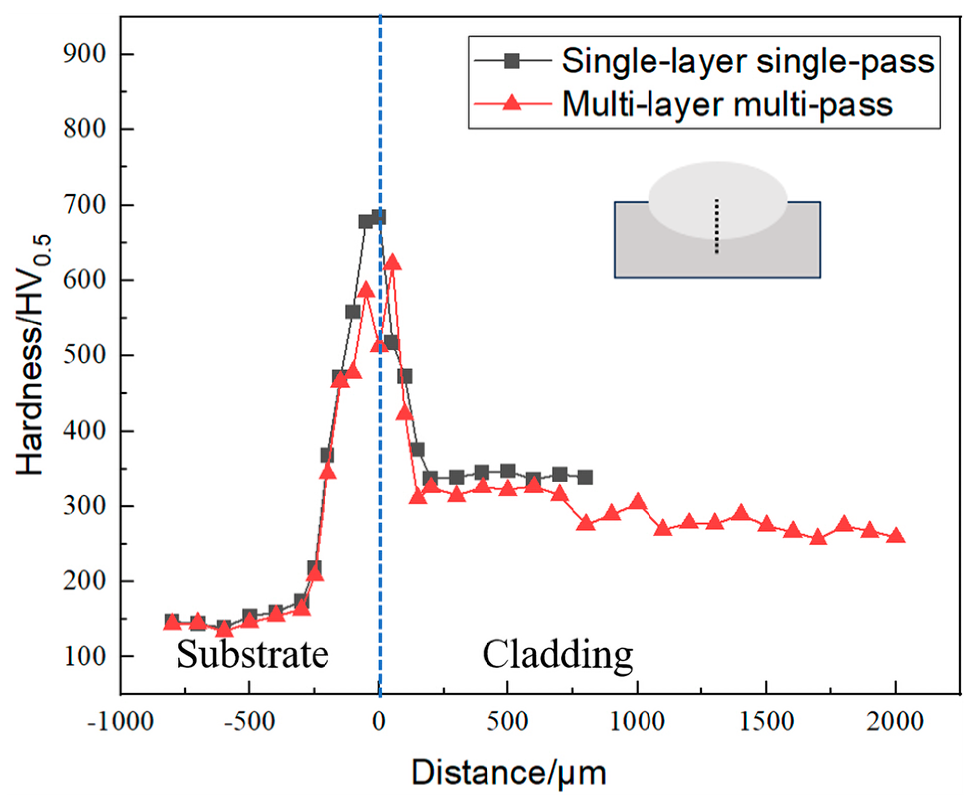
3.3. Hardness Analysis

Figure 9 shows the cross-sectional hardness distribution of the single-layer single-pass cladding samples and the multi-layer multi-pass cladding samples, with the hardness values varying with the distance from the interface centerline. The maximum hardness in the partially melted zone (PMZ) of the single-layer single-pass and multi-layer multi-pass samples is approximately 694 HV0.5 and 645 HV0.5, respectively. This indicates that the effects of the high carbon content and high cooling rates are consistent with the findings of Zhao et al. [26] and Soriano et al. [27]. The hardness primarily depends on the phase composition, and as the proportion of martensite and cementite in the PMZ increases, the hardness significantly rises. In multi-layer multi-pass cladding, the multiple heating cycles produce a tempering-like effect, reducing the hardness of the PMZ. The cladding layer exhibits a significantly higher average microhardness than the base material, due to the effects of solid solution strengthening and precipitation strengthening by the alloying elements. The average microhardness of the single-layer single-pass cladding layer is approximately 350 HV0.5, while the fine-grained and coarse-grained regions of the multi-layer multi-pass cladding layer have average hardness values of 330 HV0.5 and 265 HV0.5, respectively. In the cladding layer near the interface, the hardness is significantly higher than in regions farther from the interface. This is due to the formation of carbides from the diffusion of the carbon from the base material into the cladding layer’s iron. The regions with the highest hardness are mainly concentrated in the first cladding layer. This occurs because, after the first layer solidifies, the diffusion of carbon atoms into the subsequent layers is impeded, leading to a reduction in the hardness of the subsequent layers. Additionally, in terms of the microstructural characteristics, the first layer predominantly consists of fine-grained regions, while the subsequent layers are primarily coarse-grained regions, which is another factor contributing to the gradual decrease in hardness.

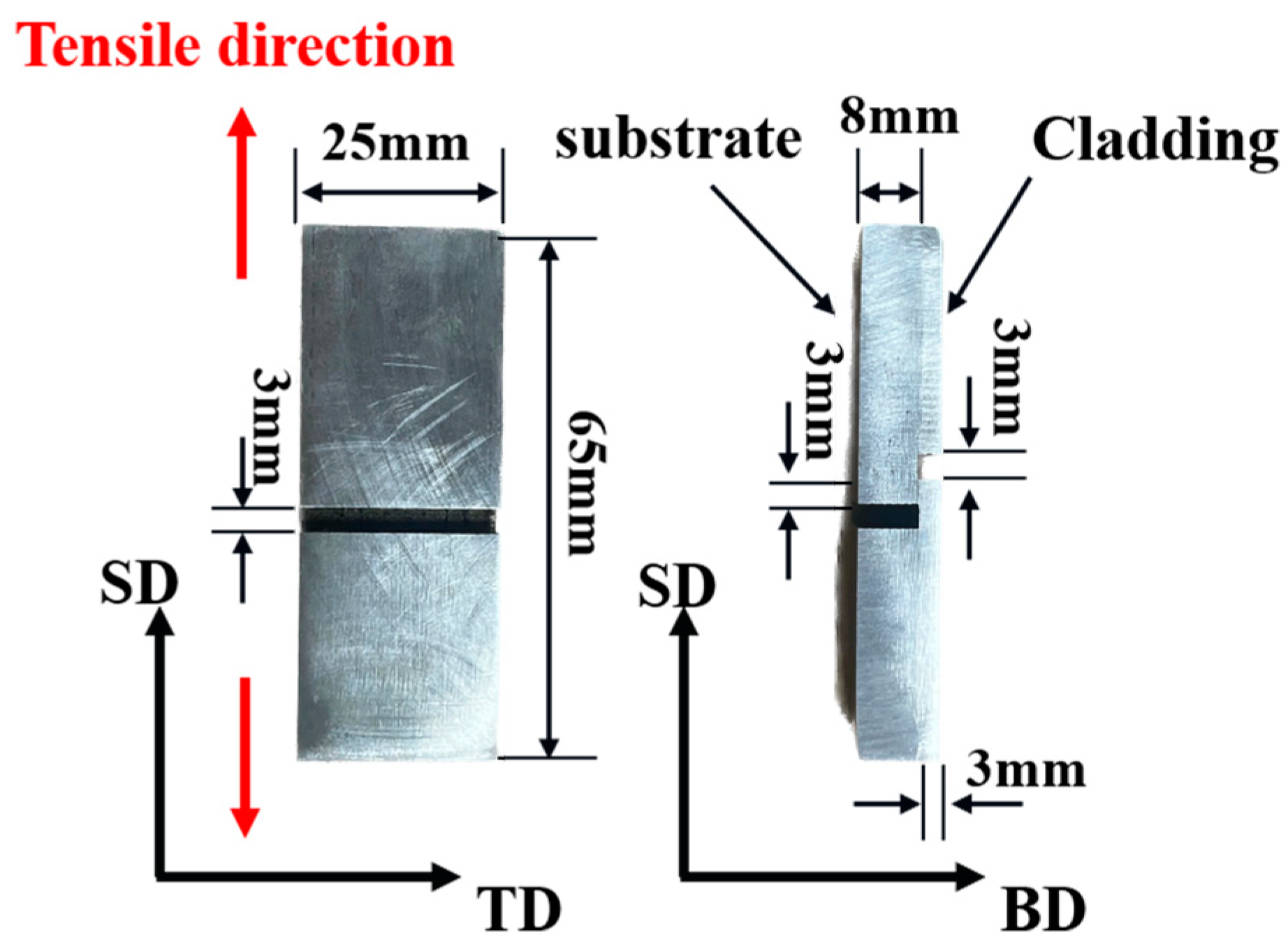
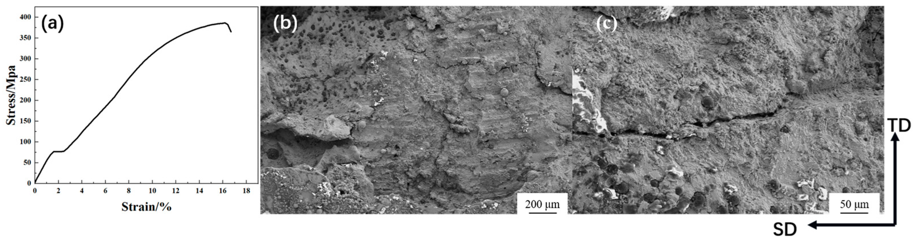
3.4. Interface Strength Analysis

The stress–strain curve of the tensile–shear samples is shown in Figure 10a. The interface bonding strength of the multi-layer multi-pass cladding samples is 386 MPa, with an elongation of 17%, which is very close to that of the QT400-18 ductile cast iron base material. Cracks occurred at the interface and propagated into the substrate, indicating that the strength of the partially melted zone was not reduced by the brittle phases. Figure 10b,c are SEM images of the fracture surfaces, showing a large number of graphite nodules distributed on the fracture surface, with an average size of about 5 μm. These graphite nodules were primarily precipitated along the grain boundaries during cooling due to the low solubility of the carbon in the cladding layer. The images reveal that the graphite nodules are densely distributed near the interface and become sparser in regions farther from the interface, showing a gradient distribution pattern. The fracture exhibits a mixed fracture mode, including features of ductile fracture, such as tear ridges and dimples, as well as brittle fracture features, such as cleavage planes and smooth fracture regions. Ductile fracture is mainly concentrated in the regions with finer grains, while brittle fracture is more pronounced in the areas with coarser grains, particularly in the dendritic regions. The precipitation of graphite nodules significantly influences the fracture behavior. Since the graphite nodules are mechanically bonded to the surrounding matrix, these interfaces often become locations of stress concentrations and serve as initiation points for crack propagation. Under external forces, cracks tend to initiate at these locations and subsequently propagate, ultimately leading to fracture.

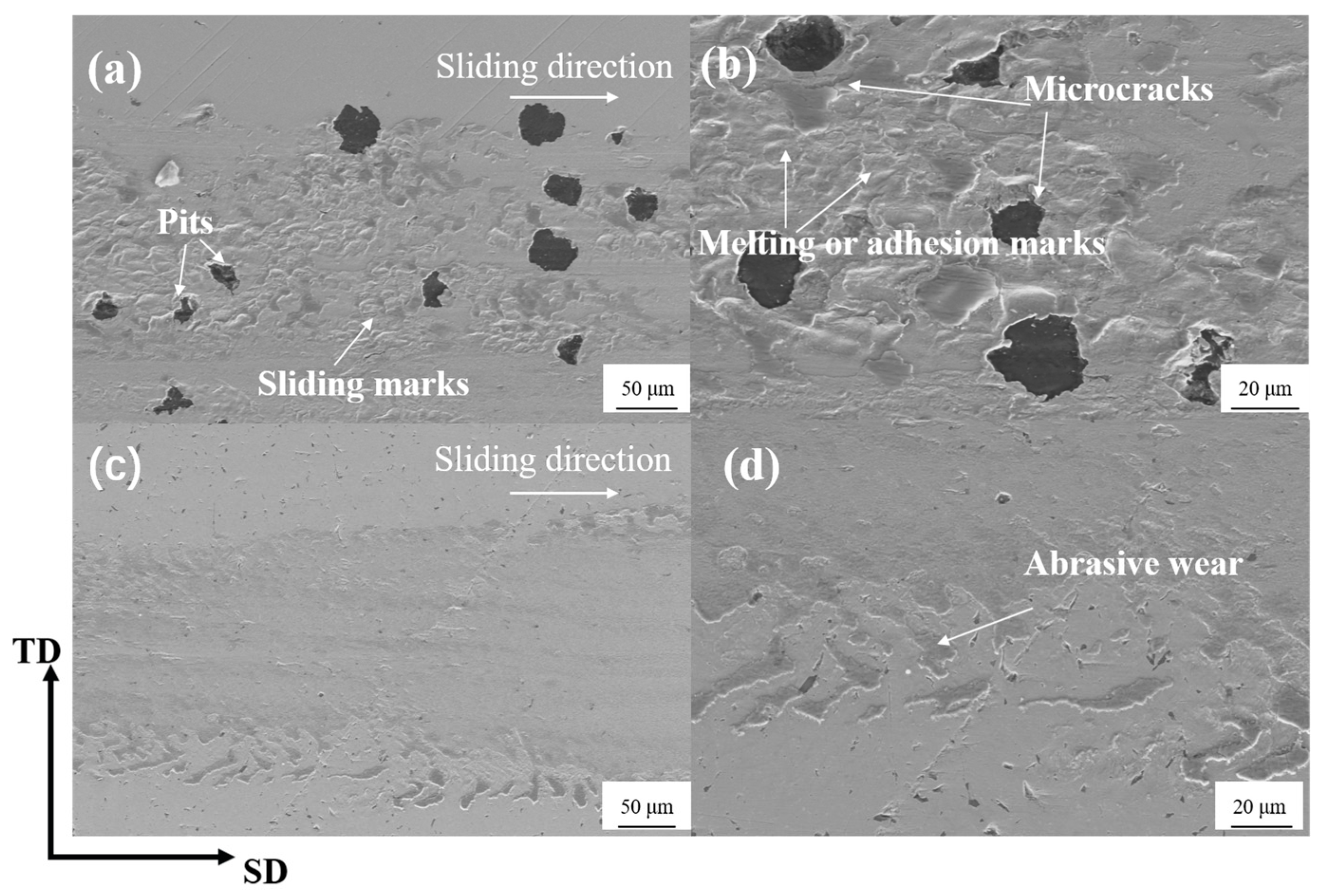
3.5. Friction and Wear Performance Analysis

As shown in Figure 11, the room-temperature friction coefficient curves of the substrate and the multi-layer multi-pass cladding layer exhibit a similar overall trend, indicating good compatibility between the wear resistance of the cladding layer and the substrate. However, the friction coefficient of the cladding layer is significantly lower than that of the substrate, a feature that is highly significant for improving the wear resistance and extending the service life of the material. The lower friction coefficient indicates that the cladding layer can better resist wear under the same conditions, reducing damage and thereby enhancing the material’s reliability and lowering maintenance costs. This performance advantage provides greater economic value and application potential for the cladding layer in practical use. The friction coefficient of the substrate shows a greater fluctuation, which may be related to the detachment and rupture of the graphite nodules within the substrate during the friction and wear tests. It may also be due to the small contact area and high contact stress during the early stages of wear. As the friction area gradually increases and the contact stress decreases, the friction coefficient tends to stabilize.
Figure 12a shows the 3D morphology of the wear scars on the substrate, where distinct deep wear grooves can be observed in the central region. The wear grooves are wide and deep, approximately 2 µm in depth, with rough and uneven edges, displaying clear characteristics of plowing and plastic deformation. The surrounding areas are uneven, with noticeable wear marks on the larger asperities. Figure 12d shows the 2D morphology of the wear scars on the cladding layer. The surface appears very smooth with almost no visible wear scars. The Z-axis fluctuation range is minimal, close to 0 µm, indicating excellent wear resistance and minimal material loss. No significant plowing marks or wear grooves are present. Figure 12b,d show the wear volume from the friction and wear tests of the substrate and the multi-layer multi-pass cladding layer, respectively. It is evident that the wear volume of the substrate after the friction and wear test (3.588 × 105 μm3) is significantly higher than that of the multi-layer, multi-pass cladding layer (1.682 × 104 μm3), suggesting that the cladding layer effectively resists plastic deformation and material removal caused by the sliding friction. This demonstrates the synergistic effect of the hard phases and the tough matrix, which significantly reduces wear.
As shown in Figure 13a, multiple pits and rough areas can be observed on the substrate surface. The pits may be associated with the detachment of the graphite nodules or localized material erosion. The clear sliding marks on the surface indicate plastic deformation and cutting effects along the sliding direction. The wear surface exhibits notable irregularities, with localized areas showing intensified deformation, possibly caused by frictional heat or applied loads. Figure 13b provides a high-magnification view of the details around the pits. The edges of the pits show irregular fracturing, likely resulting from the fatigue detachment of the graphite nodules. Some areas display melting or adhesion marks, suggesting that frictional heat may have played a role during sliding. The microcracks on the surface might be caused by fatigue damage under repeated stress. After the sliding friction wear test, the substrate exhibited typical composite wear characteristics, including adhesive wear, abrasive wear, and fatigue wear. Figure 13c,d display the wear morphology of the cladding layer. Compared to the substrate, the wear is significantly reduced, and the surface integrity is better. The images show a localized sliding marks, but no large pits or cracks are visible. The edge areas show slight plowing marks, but no significant plastic deformation is observed. The primary wear mechanism is mild abrasive wear.

4. Conclusions

In this study, laser cladding remanufacturing of ductile cast iron surfaces was achieved using 45 wt.%Fe + 55 wt.% Inconel625 powder. A systematic analysis was conducted on the grain morphology, phase structure, interface characteristics, and hardness profile of the cladding layer, including the interfacial bonding strength, and friction and wear performance. The main conclusions are as follows:
(1)
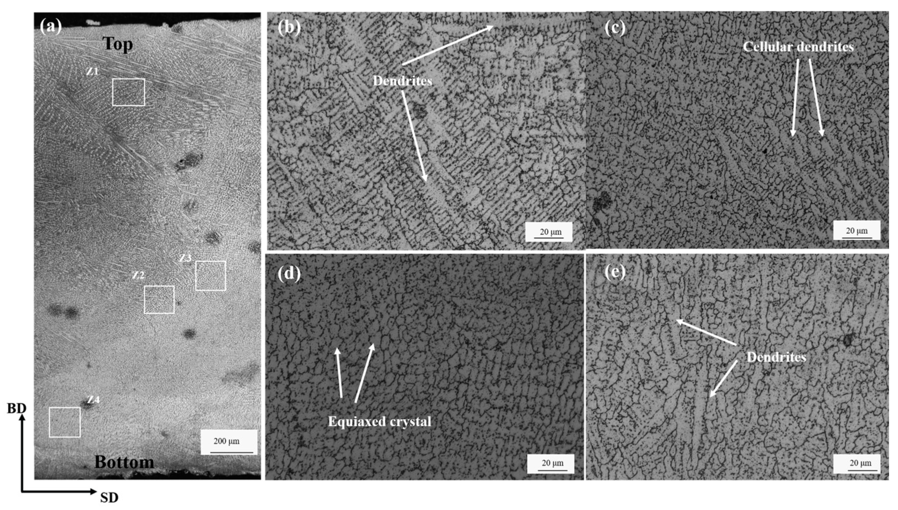
In both the single-layer single-pass and multi-layer multi-pass laser cladding processes, the grain growth morphology transitioned from the interface to the top of the clad layer. In the single-layer single-pass cladding process, the microstructure sequentially formed dendrites, cellular dendrites, and equiaxed crystal. In the multi-layer multi-pass cladding process, the sequence evolved as dendrites, cellular dendrites, equiaxed crystal, and dendrites. The XRD results indicate that the multi-layer multi-pass cladding layer primarily consisted of a γ (Ni, Fe) solid solution, accompanied by a small amount of carbides. The distribution of these carbides significantly enhanced the strength and wear resistance of the clad layer.
(2)
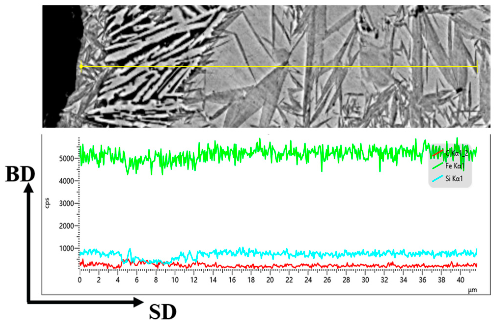
In the single-layer single-pass cladding process, a “double-shell structure” formed around the graphite spheres in the partially melted zone, with martensite in the inner layer near the graphite sphere and ledeburite in the outer layer. During the multi-layer multi-pass cladding process, the “double-shell structure” around the graphite spheres in the partially melted zone consisted of ferrite in the inner layer near the graphite sphere and ledeburite in the outer layer.
(3)
The mechanical property tests indicate that the average microhardness of the clad layer was significantly higher than that of the substrate. Specifically, the average microhardness of the single-layer single-pass clad layer was 350 HV0.5, approximately 2.1 times that of the substrate, while the multi-layer multi-pass clad layer had an average microhardness of 285 HV0.5, about 1.7 times that of the substrate. The interfacial bonding strength between the multi-layer multi-pass clad layer and the substrate reached 386 MPa, approximately 96.5% of the substrate’s strength, demonstrating an excellent metallurgical bonding performance. The average coefficient of friction (COF) of the multi-layer multi-pass clad layer (0.42) was lower than that of the substrate (0.45). The wear volume of the substrate and the multi-layer multi-pass cladding layer was 3.588 × 10⁵ μm3 and 1.682 × 10⁴ μm3, respectively. Additionally, the wear mechanism of the substrate involved a combination of adhesive wear, abrasive wear, and fatigue wear, whereas the multi-layer multi-pass clad layer primarily exhibited mild abrasive wear.

Author Contributions

Conceptualization, J.Y., P.D. and K.L.; methodology, J.Y., H.Z. and K.L.; software, J.Y. and C.L.; validation, J.Y., P.D., H.Z., X.N., C.L. and K.L.; formal analysis, J.Y.; investigation, J.Y.; resources, X.N. and C.L.; data curation, P.D.; writing—original draft preparation, J.Y.; writing—review and editing, J.Y., P.D. and H.Z.; visualization, P.D.; supervision, P.D.; project administration, P.D.; funding acquisition, X.N. All authors have read and agreed to the published version of the manuscript.

Funding

The authors are grateful for the financial support from the China Hebei Province Science and Technology Major Project: Research and Application Demonstration of Additive and Repair Technology for Key Components of Rail Vehicles (Grant No. 24292202Z).

Data Availability Statement

The original contributions presented in this study are included in the article. Further inquiries can be directed to the corresponding author.

Conflicts of Interest

Authors Xujing Niu and Chen Liang are employed by the company CRRC Tangshan Locomotive and Rolling Stock Co., Ltd. The remaining authors declare that the research was conducted in the absence of any commercial or financial relationships that could be construed as a potential conflict of interest.

References

  1. Labrecque, C.; Gagne, M. Ductile iron: Fifty years of continuous development. Can. Metall. Q. 1998, 37, 343–378. [Google Scholar] [CrossRef]
  2. Chapetti, M.D. High-cycle fatigue of austempered ductile iron (ADI). Int. J. Fatigue 2007, 29, 860–868. [Google Scholar] [CrossRef]
  3. Meneghetti, G.; Campagnolo, A.; Berto, D.; Pullin, E.; Masaggia, S. Fatigue strength of austempered ductile iron-to-steel dissimilar arc-welded joints. Weld. World 2021, 65, 667–689. [Google Scholar] [CrossRef]
  4. Cardoso, P.H.S.; Israel, C.L.; Strohaecker, T.R. Abrasive wear in Austempered Ductile Irons: A comparison with white cast irons. Wear 2014, 313, 29–33. [Google Scholar] [CrossRef]
  5. Sadeghi, A.; Moloodi, A.; Golestanipour, M.; Shahri, M.M. An investigation of abrasive wear and corrosion behavior of surface repair of gray cast iron by SMAW. J. Mater. Res. Technol. 2017, 6, 90–95. [Google Scholar] [CrossRef]
  6. Jeshvaghani, R.A.; Harati, E.; Shamanian, M. Effects of surface alloying on microstructure and wear behavior of ductile iron surface-modified with a nickel-based alloy using shielded metal arc welding. Mater. Des. 2011, 32, 1531–1536. [Google Scholar] [CrossRef]
  7. Mahmoudiniya, M.; Thorr, A.S.; Petrov, R.H.; Hermans, M.J.; Kestens, L.A. Wire arc additive manufacturing of NiFe alloy/ductile cast iron bimetallic structure; Phase transformations, microstructure and crystallographic texture. Mater. Charact. 2025, 220, 114650. [Google Scholar] [CrossRef]
  8. Lin, C.M.; Chandra, A.S.; Morales-Rivas, L.; Huang, S.Y.; Wu, H.C.; Wu, Y.E.; Tsai, H.L. Repair welding of ductile cast iron by laser cladding process: Microstructure and mechanical properties. Int. J. Cast Met. Res. 2014, 27, 378–383. [Google Scholar] [CrossRef]
  9. Ouyang, C.; Wang, R.; Zhao, C.; Wei, R.; Li, H.; Deng, R.; Bai, Q.; Liu, Y. Multi-layer laser cladding analysis and high-temperature oxidative wear behavior of cast iron with a low expansion coefficient. Surf. Coat. Technol. 2023, 474, 130079. [Google Scholar] [CrossRef]
  10. Wang, R.; Ouyang, C.; Li, Q.; Bai, Q.; Zhao, C.; Liu, Y. Study of the microstructure and corrosion properties of a Ni-based alloy coating deposited onto the surface of ductile cast iron using high-speed laser cladding. Materials 2022, 15, 1643. [Google Scholar] [CrossRef]
  11. Manoj, A.; Saurabh, A.; Narala SK, R.; Saravanan, P.; Natu, H.P.; Verma, P.C. Surface modification of grey cast iron by laser cladding for automotive brake disc application. Wear 2023, 532, 205099. [Google Scholar] [CrossRef]
  12. Liu, H.; Hao, J.; Han, Z.; Yu, G.; He, X.; Yang, H. Microstructural evolution and bonding characteristic in multi-layer laser cladding of NiCoCr alloy on compacted graphite cast iron. J. Mater. Process. Technol. 2016, 232, 153–164. [Google Scholar] [CrossRef]
  13. Li, Y.; Dong, S.; Yan, S.; Liu, X.; He, P.; Xu, B. Surface remanufacturing of ductile cast iron by laser cladding Ni-Cu alloy coatings. Surf. Coat. Technol. 2018, 347, 20–28. [Google Scholar] [CrossRef]
  14. Arias-González, F.; Del Val, J.; Comesaña, R.; Penide, J.; Lusquiños, F.; Quintero, F.; Riveiro, A.; Boutinguiza, M.; Pou, J. Fiber laser cladding of nickel-based alloy on cast iron. Appl. Surf. Sci. 2016, 374, 197–205. [Google Scholar] [CrossRef]
  15. Mazzarisi, M.; Angelastro, A.; Latte, M.; Colucci, T.; Palano, F.; Campanelli, S.L. Thermal monitoring of laser metal deposition strategies using infrared thermography. J. Manuf. Process. 2023, 85, 594–611. [Google Scholar] [CrossRef]
  16. Rezayat, M.; Aboutorabi Sani, A.; Talafi Noghani, M.; Saghafi Yazdi, M.; Taheri, M.; Moghanian, A.; Mohammadi, M.A.; Moradi, M.; Garcia, A.M.M.; Besharatloo, H. Effect of lateral laser-cladding process on the corrosion performance of Inconel 625. Metals 2023, 13, 367. [Google Scholar] [CrossRef]
  17. Latte, M.; Mazzarisi, M.; Guerra, M.G.; Campanelli, S.L.; Galantucci, L.M. Key performance indexes for the evaluation of geometrical characteristics and subsurface defects through laser line monitoring of laser metal deposition process. Opt. Laser Technol. 2025, 182, 112085. [Google Scholar] [CrossRef]
  18. Ouyang, M.; Zhu, H.; Qiu, C.; Shen, L. Laser repairing nodular cast iron with improved interface and performance using Fe-14Ni-19Cr austenitic powder. Mater. Lett. 2022, 325, 132826. [Google Scholar] [CrossRef]
  19. Yang, P.; Song, Y.; Wang, J.; Hu, F.; Xie, L. Semiconductor laser cladding of an Fe-based alloy on nodular cast iron. Weld. World 2021, 65, 785–792. [Google Scholar] [CrossRef]
  20. Weng, Z.; Wang, A.; Wang, Y.; Xiong, D.; Tang, H. Diode laser cladding of Fe-based alloy on ductile cast iron and related interfacial behavior. Surf. Coat. Technol. 2016, 286, 64–71. [Google Scholar] [CrossRef]
  21. Zafar, F.; Emadinia, O.; Conceição, J.; Vieira, M.; Reis, A. A review on direct laser deposition of Inconel 625 and Inconel 625-based composites—Challenges and prospects. Metals 2023, 13, 787. [Google Scholar] [CrossRef]
  22. Huang, J.; Liu, S.; Yu, S.; An, L.; Yu, X.; Fan, D.; Yang, F. Cladding Inconel 625 on cast iron via bypass coupling micro-plasma arc welding. J. Manuf. Process. 2020, 56, 106–115. [Google Scholar] [CrossRef]
  23. Wu, X.; Wu, Y.; Li, B.; Zhang, W.; Li, L.; Wang, Z. Investigation on the high-temperature oxidation behavior and mechanism of laser-cladded Inconel625 coating at various temperatures. Surf. Coat. Technol. 2024, 478, 130438. [Google Scholar] [CrossRef]
  24. GB/T 6396-2008; Test Methods for Mechanical and Technological Properties of Clad Steel Plates. General Administration of Quality Supervision, Inspection and Quarantine of the People’s Republic of China (AQSIQ): Beijing, China, 2008.
  25. Jack, D.H.; Jack, K.H. Invited review: Carbides and nitrides in steel. Mater. Sci. Eng. 1973, 11, 1–27. [Google Scholar] [CrossRef]
  26. Zhao, H.; Li, J.; Zheng, Z.; Wang, A.; Zeng, D.; Miao, Y. The microstructures and tribological properties of composite coatings formed via PTA surface alloying of copper on nodular cast iron. Surf. Coat. Technol. 2016, 286, 303–312. [Google Scholar] [CrossRef]
  27. Soriano, C.; Leunda, J.; Lambarri, J.; Navas, V.G.; Sanz, C. Effect of laser surface hardening on the microstructure, hardness and residual stresses of austempered ductile iron grades. Appl. Surf. Sci. 2011, 257, 7101–7106. [Google Scholar] [CrossRef]
Figure 1. (a) On-site photograph of the laser cladding additive remanufacturing process. (b) Multi-layer, multi-pass laser cladding remanufactured product.
Metals 15 00312 g001
Figure 2. Shape and size of tensile–shear test specimen.
Metals 15 00312 g002
Figure 3. Optical microstructure of single-layer single-pass cladding: (a) cross-section, (b) magnification of Z1, and (ce) magnification of Z2–Z4.
Metals 15 00312 g003
Figure 4. Optical microstructure of multi-layer multi-pass cladding: (a) cross-section and (be) magnification of Z2–Z4.
Metals 15 00312 g004
Figure 5. (a) XRD pattern of the top layer and top surface of multi-layer multi-pass cladding. (b) Distribution of alloying elements.
Metals 15 00312 g005
Figure 6. (a,b) The cross-section microstructure morphology of single-layer single-pass laser cladding.
Metals 15 00312 g006
Figure 7. The element distribution near a graphite sphere at the interface of the single-layer single-pass laser cladding.
Metals 15 00312 g007
Figure 8. (a) Interface microstructure morphology of multi-layer and multi-pass laser cladding samples. (b) magnification of Z1, (c) magnification of Z2, (d) magnification of Z3.
Metals 15 00312 g008
Figure 9. Microhardness of interface section of laser cladding sample.
Metals 15 00312 g009
Figure 10. (a) Stress–strain curves; (b,c) SEM images of fracture morphology of tensile–shear specimens.
Metals 15 00312 g010
Figure 11. Room-temperature friction coefficient curve of multi-layer and multi-pass cladding layer.
Metals 15 00312 g011
Figure 12. (a) Three-dimensional wear morphology of the substrate; (c) three-dimensional wear morphology of the multi-layer, multi-pass cladding layer; (b) wear volume of the substrate; and (d) wear volume of the multi-layer, multi-pass cladding layer.
Metals 15 00312 g012
Figure 13. (a,b) SEM images of the substrate surface after friction and wear; (c,d) SEM images of the multi-layer multi-pass cladding layer surface after friction and wear.
Metals 15 00312 g013
Table 1. Chemical composition of QT-400-18 (wt.%). Adapted from Ref. [22].
CMnSiSPMgReFe
3.5–4.0<0.352.5–3.0<0.03<0.070.03–0.060.02–0.05Res.
Table 2. Chemical composition of 45 wt. %Fe + 55 wt.% Inconel625 alloy powder. Adapted from Ref. [23].
NiCrMoNbAlTiCFe
35.5410.754.51.80.10.10.015Res.
Disclaimer/Publisher’s Note: The statements, opinions and data contained in all publications are solely those of the individual author(s) and contributor(s) and not of MDPI and/or the editor(s). MDPI and/or the editor(s) disclaim responsibility for any injury to people or property resulting from any ideas, methods, instructions or products referred to in the content.

