
Influence of Heat Treatment on the Microstructure and Mechanical Properties of FeCoNiCrMn High-Entropy Alloy Manufactured via Laser Powder Bed Fusion

 ,
, 

 ,
,  and
and 
Abstract
1. Introduction
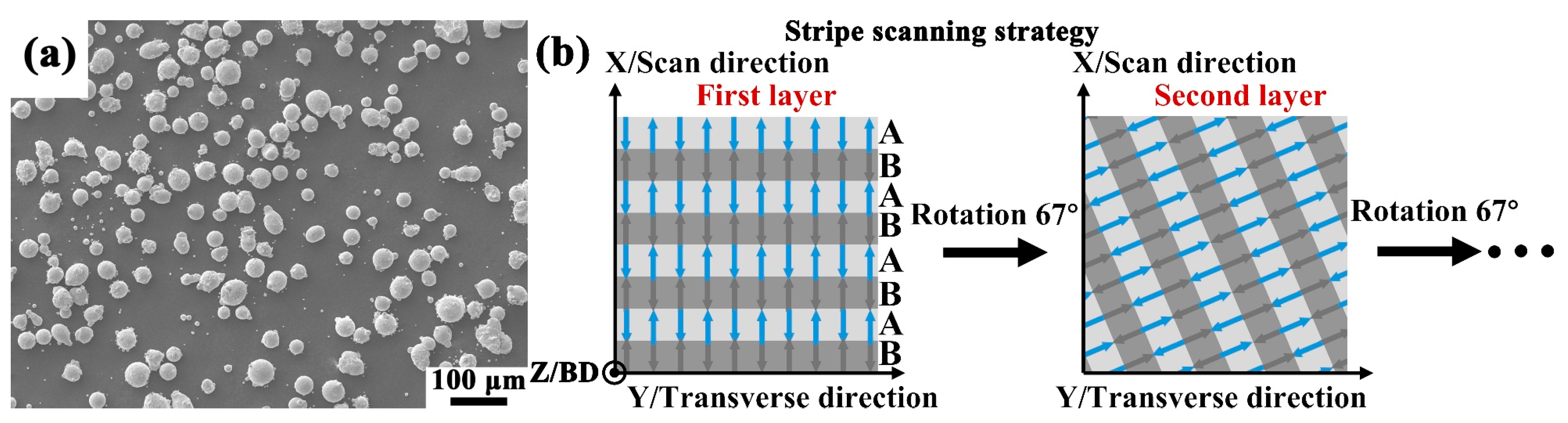
2. Materials and Methods
3. Results and Discussion
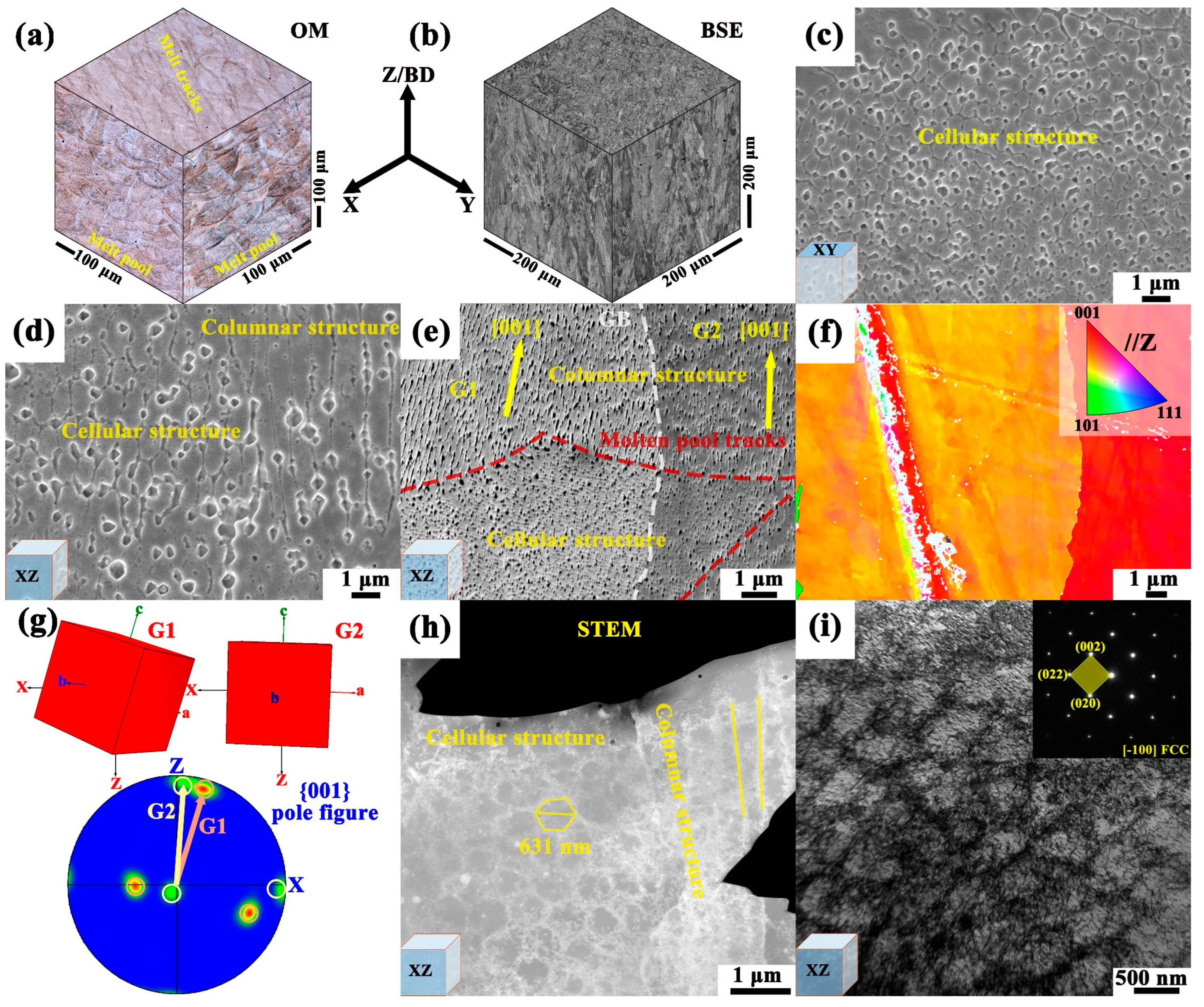
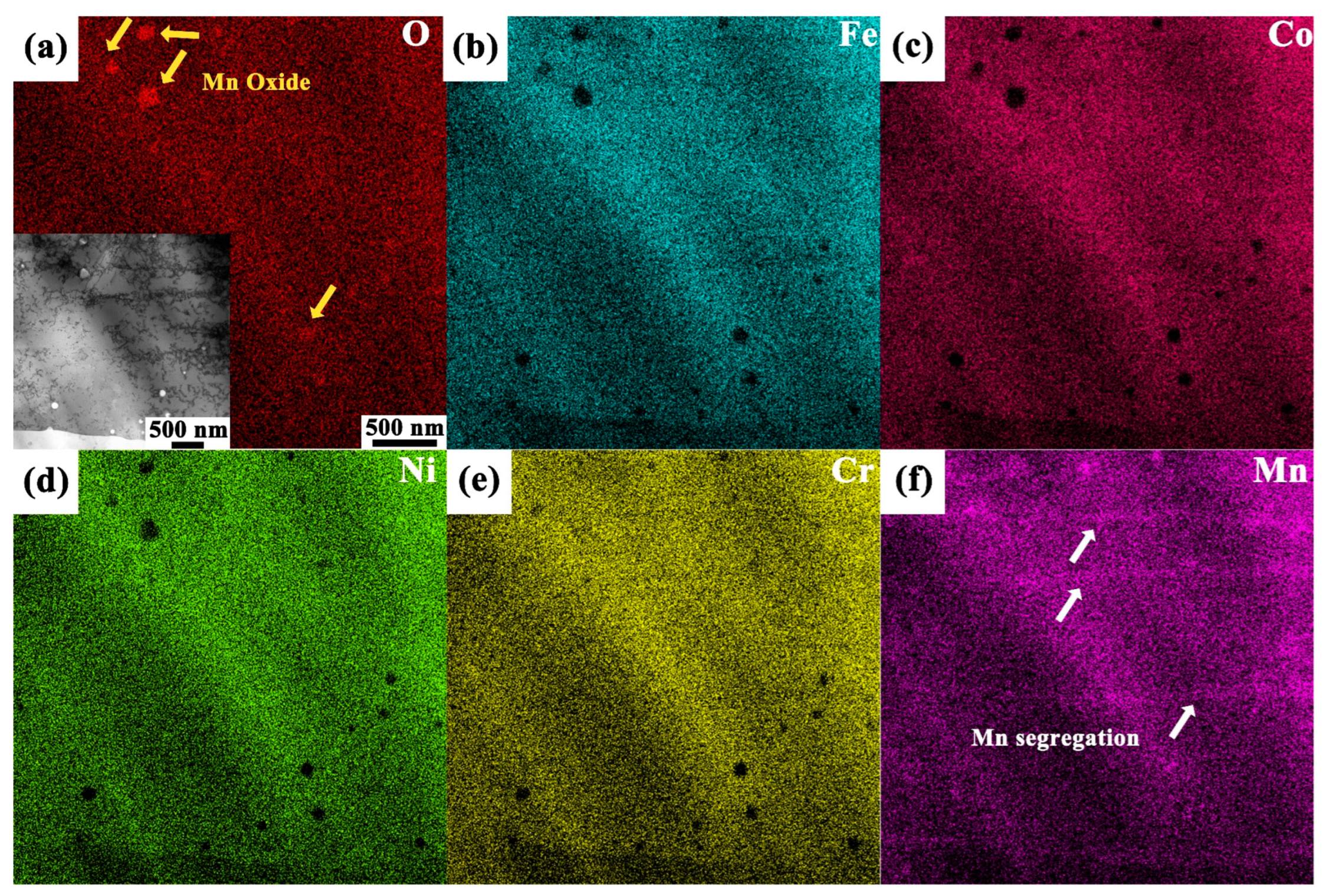
3.1. Microstructure
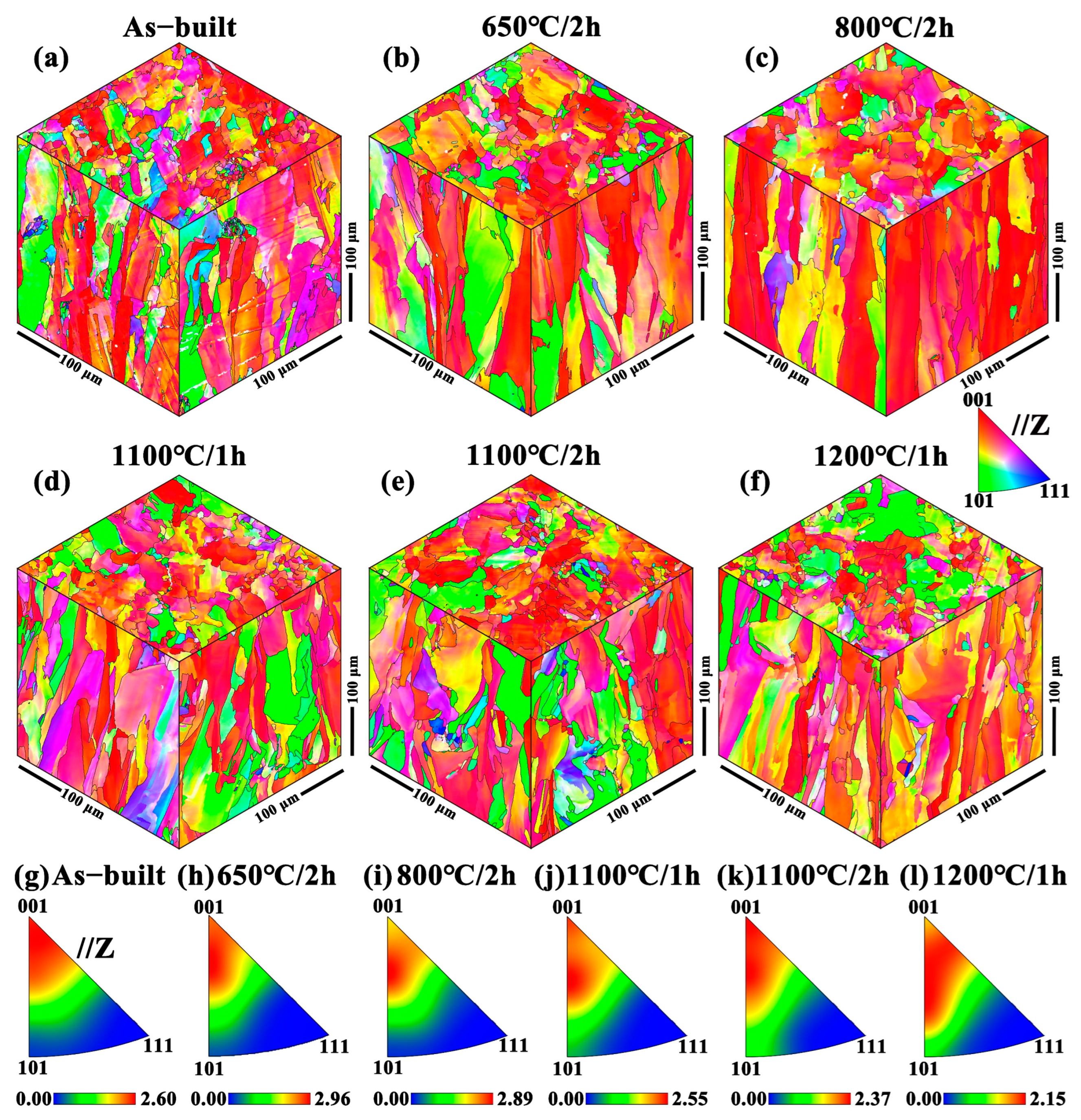
3.2. Post-Heat Treatment
3.3. Deformation Mechanism
4. Conclusions
- (1)
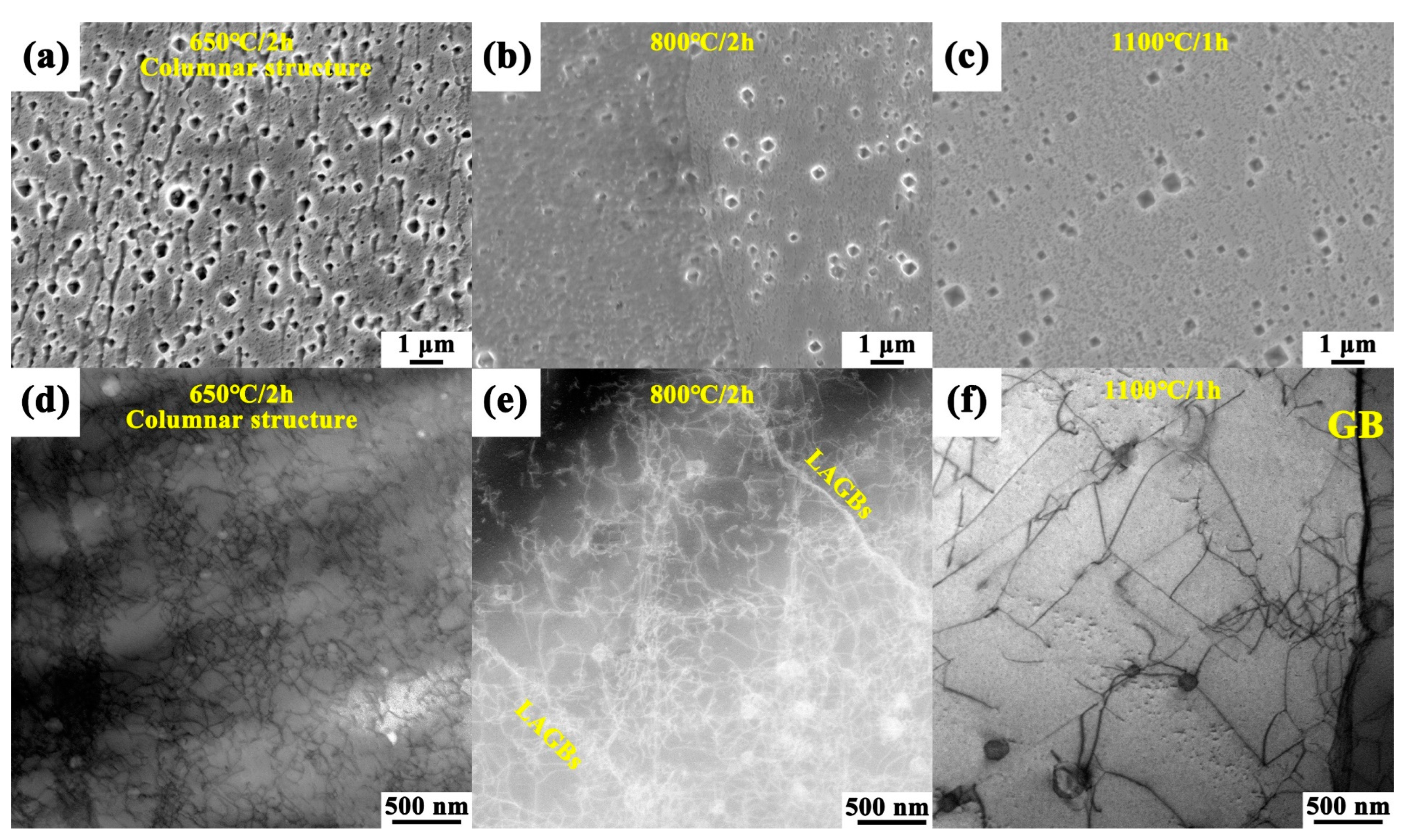
- The L-PBF FeCoNiCrMn alloy exhibited two substructures, i.e., the high-density dislocation cellular the columnar substructures. The columnar substructure demonstrated <001> epitaxial growth, resulting from the competition between the direction of maximum undercooling and the preferred growth direction.
- (2)
- The cellular substructure remained stable at temperatures up to 650 °C but began to dissipate at 800 °C. The high-density dislocation cellular substructure played a decisive role in the mechanical properties of the alloy through dislocation strengthening and grain boundary-like strengthening.
- (3)
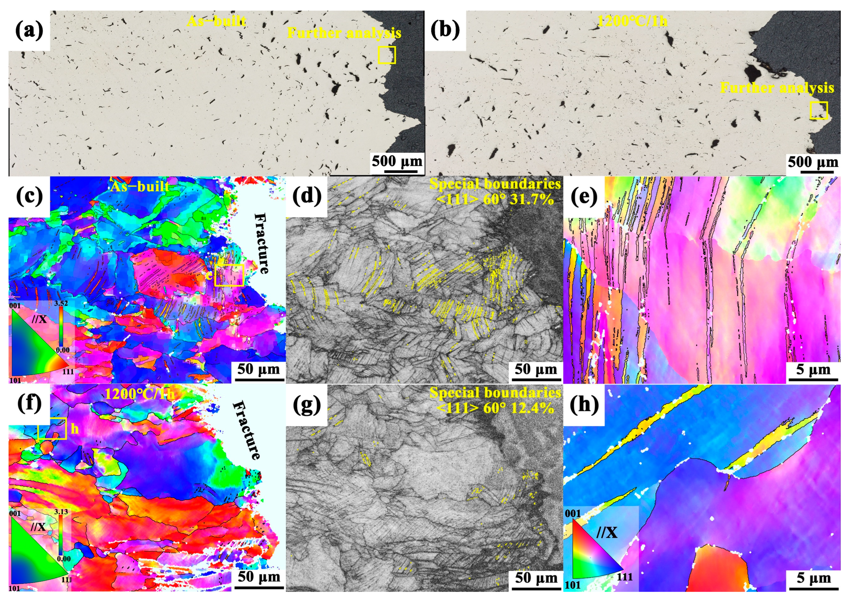
- The cellular substructure also served as a site for twin formation during subsequent deformation, facilitating twin formation and inducing grain rotation, which contributed to work hardening. In contrast, the high-temperature annealing state exhibited an increased capacity for uniform plastic deformation due to homogenization, leading to improved ductility.
Author Contributions
Funding
Data Availability Statement
Acknowledgments
Conflicts of Interest
Abbreviations
| L-PBF | Laser powder bed fusion |
| AM | Additive manufacturing |
| HEAs | High-entropy alloys |
| FCC | Face-centered cubic |
| HIP | Hot isostatic pressing |
| OM | Optical microscopy |
| SEM | Scanning electron microscopy |
| EBSD | Electron backscatter diffraction |
| TEM | Transmission electron microscopy |
| XRD | X-ray diffraction |
| SE | Secondary electron |
| BSE | Backscattered electron |
| BD | Building direction |
| SD | Scan direction |
| TD | Transverse direction |
| LD | Loading direction |
| G | Temperature gradient |
| R | Solidification rate |
| IPF | Inverse pole figure |
| PF | Pole figure |
| BC | Band contrast |
| LAGBs | Low-angle grain boundaries |
| HAGBs | High-angle grain boundaries |
| GB | Grain boundary |
References
- Cantor, B. Multicomponent high-entropy Cantor alloys. Prog. Mater. Sci. 2021, 120, 100754. [Google Scholar] [CrossRef]
- Cantor, B.; Chang, I.T.H.; Knight, P.; Vincent, A.J.B. Microstructural development in equiatomic multicomponent alloys. Mater. Sci. Eng. A 2004, 375, 213–218. [Google Scholar] [CrossRef]
- Yeh, J.W.; Chen, S.K.; Lin, S.J.; Gan, J.Y.; Chin, T.S.; Shun, T.T.; Tsau, C.H.; Chang, S.Y. Nanostructured High-Entropy Alloys with Multiple Principal Elements: Novel Alloy Design Concepts and Outcomes. Adv. Eng. Mater. 2004, 6, 299–303. [Google Scholar] [CrossRef]
- George, E.P.; Raabe, D.; Ritchie, R.O. High-entropy alloys. Nat. Rev. Mater. 2019, 4, 515–534. [Google Scholar] [CrossRef]
- He, J.Y.; Wang, H.; Huang, H.L.; Xu, X.D.; Chen, M.W.; Wu, Y.; Liu, X.J.; Nieh, T.G.; An, K.; Lu, Z.P. A precipitation-hardened high-entropy alloy with outstanding tensile properties. Acta Mater. 2016, 102, 187–196. [Google Scholar] [CrossRef]
- He, J.Y.; Liu, W.H.; Wang, H.; Wu, Y.; Liu, X.J.; Nieh, T.G.; Lu, Z.P. Effects of Al addition on structural evolution and tensile properties of the FeCoNiCrMn high-entropy alloy system. Acta Mater. 2014, 62, 105–113. [Google Scholar] [CrossRef]
- Lee, C.; Song, G.; Gao, M.C.; Feng, R.; Chen, P.; Brechtl, J.; Chen, Y.; An, K.; Guo, W.; Poplawsky, J.D.; et al. Lattice distortion in a strong and ductile refractory high-entropy alloy. Acta Mater. 2018, 160, 158–172. [Google Scholar] [CrossRef]
- Xiang, S.; Luan, H.; Wu, J.; Yao, K.-F.; Li, J.; Liu, X.; Tian, Y.; Mao, W.; Bai, H.; Le, G.; et al. Microstructures and mechanical properties of CrMnFeCoNi high entropy alloys fabricated using laser metal deposition technique. J. Alloys Compd. 2019, 773, 387–392. [Google Scholar] [CrossRef]
- Chen, C.; Zhang, W.; Zhang, E.; Wang, W.; Wei, R.; Chen, J.; Yuan, S.; Wang, T.; Zhang, T.; Guan, S.; et al. Microstructure of and mechanical properties of an as-cast fine-grain dual-phase Fe-based high entropy alloy formed via solid-state phase transformation. Mater. Sci. Eng. A 2022, 838, 142779. [Google Scholar] [CrossRef]
- Gludovatz, B.; George, E.P.; Ritchie, R.O. Processing, Microstructure and Mechanical Properties of the CrMnFeCoNi High-Entropy Alloy. JOM 2015, 67, 2262–2270. [Google Scholar] [CrossRef]
- Chou, T.H.; Huang, J.C.; Yang, C.H.; Lin, S.K.; Nieh, T.G. Consideration of kinetics on intermetallics formation in solid-solution high entropy alloys. Acta Mater. 2020, 195, 71–80. [Google Scholar] [CrossRef]
- Miracle, D.B.; Senkov, O.N. A critical review of high entropy alloys and related concepts. Acta Mater. 2017, 122, 448–511. [Google Scholar] [CrossRef]
- Lu, C.; Niu, L.; Chen, N.; Jin, K.; Yang, T.; Xiu, P.; Zhang, Y.; Gao, F.; Bei, H.; Shi, S.; et al. Enhancing radiation tolerance by controlling defect mobility and migration pathways in multicomponent single-phase alloys. Nat. Commun. 2016, 7, 13564. [Google Scholar] [CrossRef] [PubMed]
- He, J.; Wang, Q.; Zhang, H.; Dai, L.; Mukai, T.; Wu, Y.; Liu, X.; Wang, H.; Nieh, T.G.; Lu, Z. Dynamic deformation behavior of a face-centered cubic FeCoNiCrMn high-entropy alloy. Sci. Bull. 2018, 63, 362–368. [Google Scholar] [CrossRef]
- Zhu, Y.; Zhang, K.; Meng, Z.; Zhang, K.; Hodgson, P.; Birbilis, N.; Weyland, M.; Fraser, H.L.; Lim, S.C.V.; Peng, H.; et al. Ultrastrong nanotwinned titanium alloys through additive manufacturing. Nat. Mater. 2022, 21, 1258–1262. [Google Scholar] [CrossRef] [PubMed]
- Liu, Z.; Zhao, D.; Wang, P.; Yan, M.; Yang, C.; Chen, Z.; Lu, J.; Lu, Z. Additive manufacturing of metals: Microstructure evolution and multistage control. J. Mater. Sci. Technol. 2022, 100, 224–236. [Google Scholar] [CrossRef]
- Wang, H.; Zhu, Z.G.; Chen, H.; Wang, A.G.; Liu, J.Q.; Liu, H.W.; Zheng, R.K.; Nai, S.M.L.; Primig, S.; Babu, S.S.; et al. Effect of cyclic rapid thermal loadings on the microstructural evolution of a CrMnFeCoNi high-entropy alloy manufactured by selective laser melting. Acta Mater. 2020, 196, 609–625. [Google Scholar] [CrossRef]
- Xu, Z.; Zhang, H.; Li, W.; Mao, A.; Wang, L.; Song, G.; He, Y. Microstructure and nanoindentation creep behavior of CoCrFeMnNi high-entropy alloy fabricated by selective laser melting. Addit. Manuf. 2019, 28, 766–771. [Google Scholar] [CrossRef]
- Li, Z. Interstitial equiatomic CoCrFeMnNi high-entropy alloys: Carbon content, microstructure, and compositional homogeneity effects on deformation behavior. Acta Mater. 2019, 164, 400–412. [Google Scholar] [CrossRef]
- Yu, P.; Fan, N.; Zhang, Y.; Wang, Z.; Li, W.; Lupoi, R.; Yin, S. Microstructure evolution and composition redistribution of FeCoNiCrMn high entropy alloy under extreme plastic deformation. Mater. Res. Lett. 2022, 10, 124–132. [Google Scholar] [CrossRef]
- Zhang, W.; Shen, J.; Oliveira, J.P.; Kooi, B.J.; Pei, Y. Crystallographic orientation-dependent deformation characteristics of additive manufactured interstitial-strengthened high entropy alloys. Scr. Mater. 2023, 222, 115049. [Google Scholar] [CrossRef]
- Wang, N.; Cao, Q.; Wang, X.; Ding, S.; Zhang, D.; Jiang, J.-Z. Unusual deformation-induced martensitic transformation in Fe-Co-Ni-Cr-Mn high entropy alloy thin films. J. Alloys Compd. 2022, 920, 165959. [Google Scholar] [CrossRef]
- Bajaj, D.; Feng, A.H.; Qu, S.J.; Li, D.Y.; Chen, D.L. Orientation-dependent lattice rotation and phase transformation in an additively manufactured high-entropy alloy. J. Mater. Sci. Technol. 2025, 227, 11–25. [Google Scholar] [CrossRef]
- Otto, F.; Dlouhý, A.; Somsen, C.; Bei, H.; Eggeler, G.; George, E.P. The influences of temperature and microstructure on the tensile properties of a CoCrFeMnNi high-entropy alloy. Acta Mater. 2013, 61, 5743–5755. [Google Scholar] [CrossRef]
- Huang, S.; Li, W.; Lu, S.; Tian, F.; Shen, J.; Holmström, E.; Vitos, L. Temperature dependent stacking fault energy of FeCrCoNiMn high entropy alloy. Scr. Mater. 2015, 108, 44–47. [Google Scholar] [CrossRef]
- An, Z.; Mao, S.; Liu, Y.; Yang, L.; Vayyala, A.; Wei, X.; Liu, C.; Shi, C.; Jin, H.; Liu, C.; et al. Inherent and multiple strain hardening imparting synergistic ultrahigh strength and ductility in a low stacking faulted heterogeneous high-entropy alloy. Acta Mater. 2023, 243, 118516. [Google Scholar] [CrossRef]
- Zhu, Z.G.; Nguyen, Q.B.; Ng, F.L.; An, X.H.; Liao, X.Z.; Liaw, P.K.; Nai, S.M.L.; Wei, J. Hierarchical microstructure and strengthening mechanisms of a CoCrFeNiMn high entropy alloy additively manufactured by selective laser melting. Scr. Mater. 2018, 154, 20–24. [Google Scholar] [CrossRef]
- Pham, M.-S.; Dovgyy, B.; Hooper, P.A.; Gourlay, C.M.; Piglione, A. The role of side-branching in microstructure development in laser powder-bed fusion. Nat. Commun. 2020, 11, 749. [Google Scholar] [CrossRef] [PubMed]
- Melia, M.A.; Carroll, J.D.; Whetten, S.R.; Esmaeely, S.N.; Locke, J.; White, E.; Anderson, I.; Chandross, M.; Michael, J.R.; Argibay, N.; et al. Mechanical and Corrosion Properties of Additively Manufactured CoCrFeMnNi High Entropy Alloy. Addit. Manuf. 2019, 29, 100833. [Google Scholar] [CrossRef]
- Joseph, J.; Hodgson, P.; Jarvis, T.; Wu, X.; Stanford, N.; Fabijanic, D.M. Effect of hot isostatic pressing on the microstructure and mechanical properties of additive manufactured AlxCoCrFeNi high entropy alloys. Mater. Sci. Eng. A 2018, 733, 59–70. [Google Scholar] [CrossRef]
- Zhang, C.; Feng, K.; Kokawa, H.; Han, B.; Li, Z. Cracking mechanism and mechanical properties of selective laser melted CoCrFeMnNi high entropy alloy using different scanning strategies. Mater. Sci. Eng. A 2020, 789, 139672. [Google Scholar] [CrossRef]
- Liu, L.; Ding, Q.; Zhong, Y.; Zou, J.; Wu, J.; Chiu, Y.-L.; Li, J.; Zhang, Z.; Yu, Q.; Shen, Z. Dislocation network in additive manufactured steel breaks strength–ductility trade-off. Mater. Today 2018, 21, 354–361. [Google Scholar] [CrossRef]
- Liu, F.C.; Feng, A.H.; Pei, X.; Hovanski, Y.; Mishra, R.S.; Ma, Z.Y. Friction stir based welding, processing, extrusion and additive manufacturing. Prog. Mater. Sci. 2024, 146, 101330. [Google Scholar] [CrossRef]
- Li, R.; Niu, P.; Yuan, T.; Cao, P.; Chen, C.; Zhou, K. Selective laser melting of an equiatomic CoCrFeMnNi high-entropy alloy: Processability, non-equilibrium microstructure and mechanical property. J. Alloys Compd. 2018, 746, 125–134. [Google Scholar] [CrossRef]
- Park, J.M.; Kim, E.S.; Kwon, H.; Sathiyamoorthi, P.; Kim, K.T.; Yu, J.-H.; Kim, H.S. Effect of heat treatment on microstructural heterogeneity and mechanical properties of 1%C-CoCrFeMnNi alloy fabricated by selective laser melting. Addit. Manuf. 2021, 47, 102283. [Google Scholar] [CrossRef]
- Chen, X.; Kong, J.; Feng, S.; Dong, K.; Liang, Y.; Wang, Q.; Yang, Y.; Liu, X. A precipitation-strengthened high-entropy alloy prepared by selective laser melting in-situ alloying and post-heat treatment. J. Alloys Compd. 2023, 936, 168145. [Google Scholar] [CrossRef]
- Bai, Y.; Jiang, H.; Yan, K.; Li, M.; Wei, Y.; Zhang, K.; Wei, B. Phase transition and heterogeneous strengthening mechanism in CoCrFeNiMn high-entropy alloy fabricated by laser-engineered net shaping via annealing at intermediate-temperature. J. Mater. Sci. Technol. 2021, 92, 129–137. [Google Scholar] [CrossRef]
- Kong, D.; Dong, C.; Wei, S.; Ni, X.; Zhang, L.; Li, R.; Wang, L.; Man, C.; Li, X. About metastable cellular structure in additively manufactured austenitic stainless steels. Addit. Manuf. 2021, 38, 101804. [Google Scholar] [CrossRef]
- Voisin, T.; Forien, J.-B.; Perron, A.; Aubry, S.; Bertin, N.; Samanta, A.; Baker, A.; Wang, Y.M. New insights on cellular structures strengthening mechanisms and thermal stability of an austenitic stainless steel fabricated by laser powder-bed-fusion. Acta Mater. 2021, 203, 116476. [Google Scholar] [CrossRef]
- Gao, S.; Hu, Z.; Duchamp, M.; Krishnan, P.S.S.R.; Tekumalla, S.; Song, X.; Seita, M. Recrystallization-based grain boundary engineering of 316L stainless steel produced via selective laser melting. Acta Mater. 2020, 200, 366–377. [Google Scholar] [CrossRef]
- Li, W.; Huang, Y.; Xie, Z.; Chen, H.; Li, W.; Liu, B.; Wang, B. Mechanical property and cellular structure of an additive manufactured FeCoNiCrMo0.2 high-entropy alloy at high-velocity deformation. J. Mater. Sci. Technol. 2023, 139, 156–166. [Google Scholar] [CrossRef]
- DebRoy, T.; Wei, H.L.; Zuback, J.S.; Mukherjee, T.; Elmer, J.W.; Milewski, J.O.; Beese, A.M.; Wilson-Heid, A.; De, A.; Zhang, W. Additive manufacturing of metallic components—Process, structure and properties. Prog. Mater. Sci. 2018, 92, 112–224. [Google Scholar] [CrossRef]
- Wu, Z.; Bei, H.; Otto, F.; Pharr, G.M.; George, E.P. Recovery, recrystallization, grain growth and phase stability of a family of FCC-structured multi-component equiatomic solid solution alloys. Intermetallics 2014, 46, 131–140. [Google Scholar] [CrossRef]
- Tong, Z.; Ren, X.; Jiao, J.; Zhou, W.; Ren, Y.; Ye, Y.; Larson, E.A.; Gu, J. Laser additive manufacturing of FeCrCoMnNi high-entropy alloy: Effect of heat treatment on microstructure, residual stress and mechanical property. J. Alloys Compd. 2019, 785, 1144–1159. [Google Scholar] [CrossRef]
- Otto, F.; Yang, Y.; Bei, H.; George, E.P. Relative effects of enthalpy and entropy on the phase stability of equiatomic high-entropy alloys. Acta Mater. 2013, 61, 2628–2638. [Google Scholar] [CrossRef]
- Bajaj, D.; Chen, Z.; Qu, S.J.; Feng, A.H.; Li, D.Y.; Chen, D.L. Distinct origins of deformation twinning in an additively-manufactured high-entropy alloy. Addit. Manuf. 2023, 74, 103716. [Google Scholar] [CrossRef]
- Chierchia, R.; Böttcher, T.; Heinke, H.; Einfeldt, S.; Figge, S.; Hommel, D. Microstructure of heteroepitaxial GaN revealed by X-ray diffraction. J. Appl. Phys. 2003, 93, 8918–8925. [Google Scholar] [CrossRef]
- Wu, D.; Xu, Y.; Li, W.; Fan, N.; Yang, Y.; Yin, S. Significant improvement of mechanical properties of cold-spray-additive manufactured FeCoNiCrMn high-entropy alloy via post-annealing. Mater. Charact. 2023, 206, 113350. [Google Scholar] [CrossRef]
- Tong, Z.; Wan, W.; Liu, H.; Zhou, W.; Ye, Y.; Ren, X. Combination of annealing and laser shock peening for tailoring microstructure and mechanical properties of laser directed energy deposited CrMnFeCoNi high-entropy alloy. Addit. Manuf. 2023, 61, 103345. [Google Scholar] [CrossRef]
- Sangid, M.D.; Book, T.A.; Naragani, D.; Rotella, J.; Ravi, P.; Finch, A.; Kenesei, P.; Park, J.-S.; Sharma, H.; Almer, J.; et al. Role of heat treatment and build orientation in the microstructure sensitive deformation characteristics of IN718 produced via SLM additive manufacturing. Addit. Manuf. 2018, 22, 479–496. [Google Scholar] [CrossRef]
- Zheng, M.; Li, C.; Zhang, X.; Ye, Z.; Yang, X.; Gu, J. The influence of columnar to equiaxed transition on deformation behavior of FeCoCrNiMn high entropy alloy fabricated by laser-based directed energy deposition. Addit. Manuf. 2021, 37, 101660. [Google Scholar] [CrossRef]
- Wang, B.; Wang, X.; Li, Z.; Ma, R.; Zhao, S.; Xie, F.; Zhang, X. Shear localization and microstructure in coarse grained beta titanium alloy. Mater. Sci. Eng. A 2016, 652, 287–295. [Google Scholar] [CrossRef]
- Zheng, M.; Li, C.; Zhang, L.; Zhang, X.; Ye, Z.; Yang, X.; Gu, J. In-situ investigation of deformation behavior in additively manufactured FeCoCrNiMn high entropy alloy. Mater. Sci. Eng. A 2022, 840, 142933. [Google Scholar] [CrossRef]
- Chen, H.; Liu, Y.; Wang, Y.; Li, Z.; Wang, D.; Kosiba, K. Temperature-dependent dynamic compressive properties and failure mechanisms of the additively manufactured CoCrFeMnNi high entropy alloy. Mater. Des. 2022, 224, 111324. [Google Scholar] [CrossRef]
- Liu, Y.; Ren, J.; Guan, S.; Li, C.; Zhang, Y.; Muskeri, S.; Liu, Z.; Yu, D.; Chen, Y.; An, K.; et al. Microstructure and mechanical behavior of additively manufactured CoCrFeMnNi high-entropy alloys: Laser directed energy deposition versus powder bed fusion. Acta Mater. 2023, 250, 118884. [Google Scholar] [CrossRef]
- Wang, Y.M.; Voisin, T.; McKeown, J.T.; Ye, J.; Calta, N.P.; Li, Z.; Zeng, Z.; Zhang, Y.; Chen, W.; Roehling, T.T.; et al. Additively manufactured hierarchical stainless steels with high strength and ductility. Nat. Mater. 2018, 17, 63–71. [Google Scholar] [CrossRef]
- Liu, C.; Wang, Y.; Zhang, Y.; Zhang, L.-C.; Wang, L. Deformation mechanisms of additively manufactured TiNbTaZrMo refractory high-entropy alloy: The role of cellular structure. Int. J. Plast. 2024, 173, 103884. [Google Scholar] [CrossRef]
- Li, H.G.; Huang, Y.J.; Zhao, W.J.; Chen, T.; Sun, J.F.; Wei, D.Q.; Du, Q.; Zou, Y.C.; Lu, Y.Z.; Zhu, P.; et al. Overcoming the strength-ductility trade-off in an additively manufactured CoCrFeMnNi high entropy alloy via deep cryogenic treatment. Addit. Manuf. 2022, 50, 102546. [Google Scholar] [CrossRef]

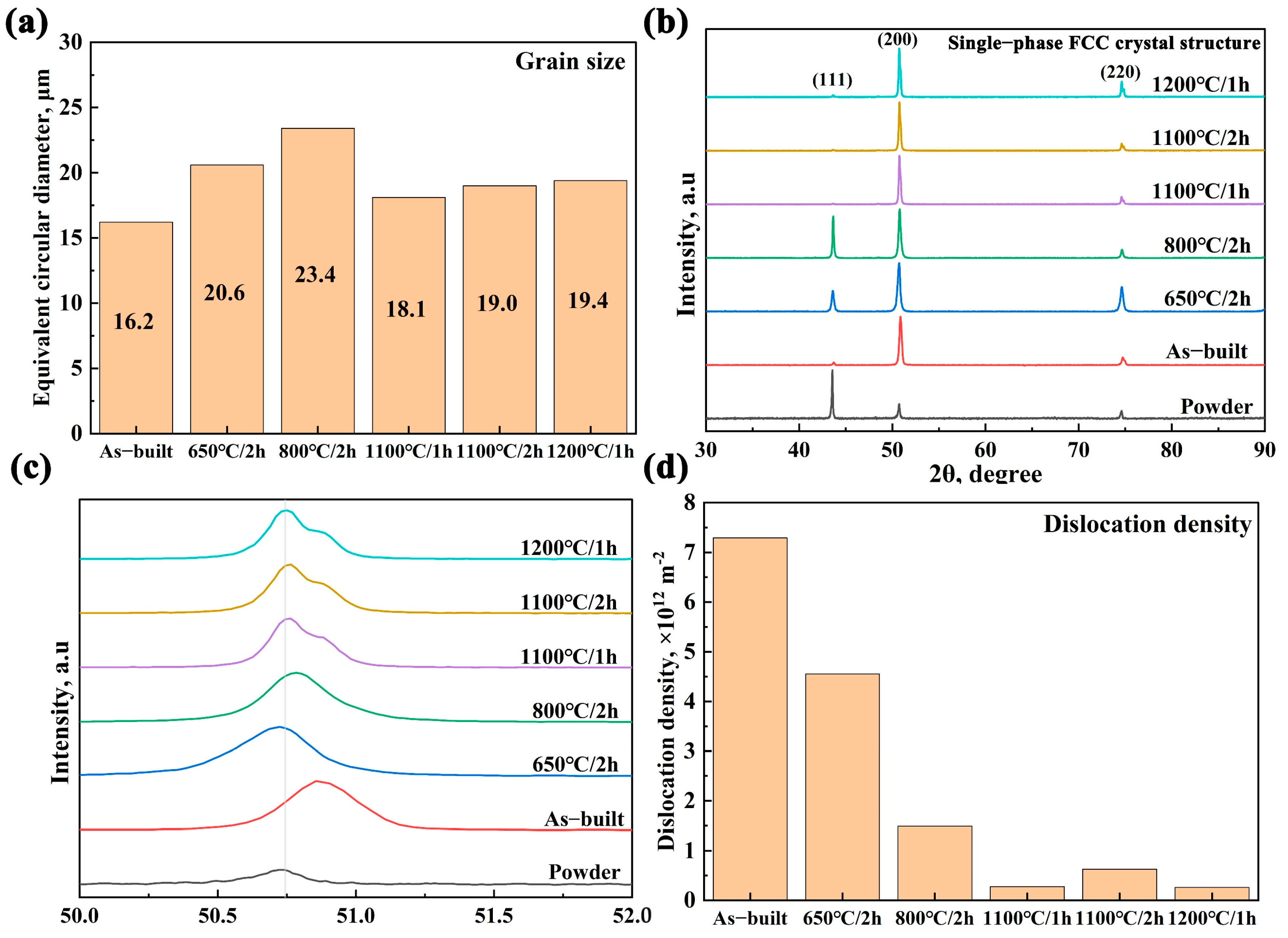
| Sample | βobs (in deg.) | βinst (in deg.) | β = βobs − βinst (in rad.) | Dislocation Density (in m−2) |
|---|---|---|---|---|
| As-built | 0.314 | 0.232 | 0.00143 | 7.286 × 10¹² |
| 650 °C/2 h | 0.297 | 0.232 | 0.00113 | 4.550 × 10¹² |
| 800 °C/2 h | 0.269 | 0.232 | 0.000646 | 1.487 × 10¹² |
| 1100 °C/1 h | 0.248 | 0.232 | 0.000279 | 2.774 × 10¹¹ |
| 1100 °C/2 h | 0.256 | 0.232 | 0.000419 | 6.256 × 10¹¹ |
| 1200 °C/1 h | 0.245 | 0.232 | 0.000269 | 2.578 × 10¹¹ |
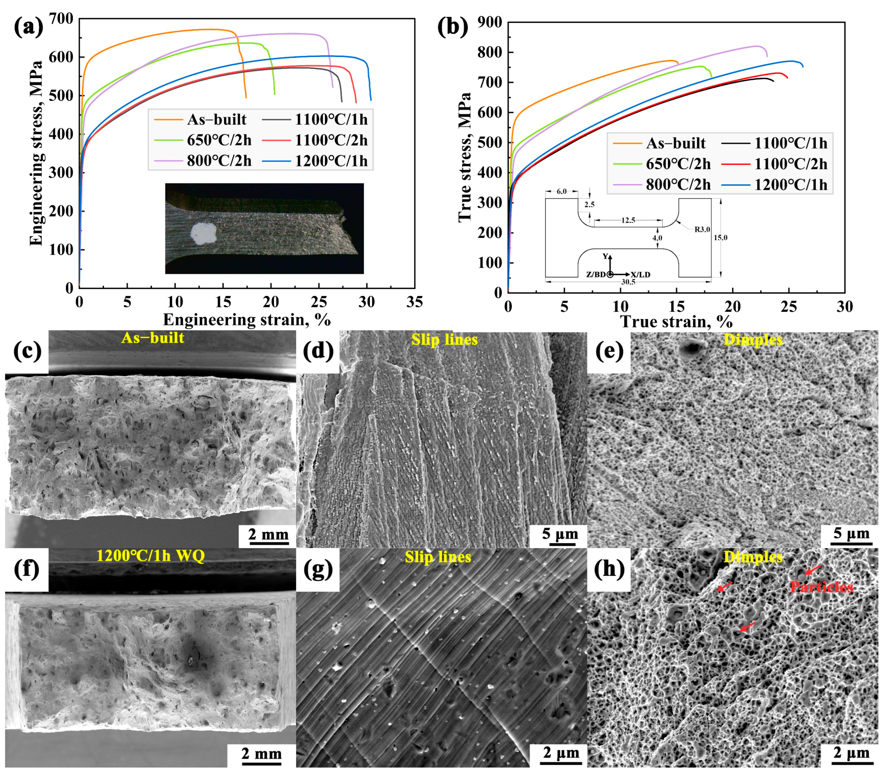
| Sample | σy, MPa | σUTS, MPa | Elongation, % |
|---|---|---|---|
| As-built | 547 | 672 | 16.6 |
| 650 °C/2 h | 468 | 636 | 19.8 |
| 800 °C/2 h | 453 | 661 | 26.0 |
| 1100 °C/1 h | 346 | 572 | 27.1 |
| 1100 °C/2 h | 335 | 578 | 28.5 |
| 1200 °C/1 h | 345 | 603 | 30.2 |
Disclaimer/Publisher’s Note: The statements, opinions and data contained in all publications are solely those of the individual author(s) and contributor(s) and not of MDPI and/or the editor(s). MDPI and/or the editor(s) disclaim responsibility for any injury to people or property resulting from any ideas, methods, instructions or products referred to in the content. |
© 2025 by the authors. Licensee MDPI, Basel, Switzerland. This article is an open access article distributed under the terms and conditions of the Creative Commons Attribution (CC BY) license (https://creativecommons.org/licenses/by/4.0/).
Share and Cite
Liang, J.; Zhu, G.; Sun, J.; Qu, S.; Jiang, J.; Cao, G.; Wang, H.; Shen, J.; Feng, A.; Chen, D. Influence of Heat Treatment on the Microstructure and Mechanical Properties of FeCoNiCrMn High-Entropy Alloy Manufactured via Laser Powder Bed Fusion. Metals 2025, 15, 260. https://doi.org/10.3390/met15030260
Liang J, Zhu G, Sun J, Qu S, Jiang J, Cao G, Wang H, Shen J, Feng A, Chen D. Influence of Heat Treatment on the Microstructure and Mechanical Properties of FeCoNiCrMn High-Entropy Alloy Manufactured via Laser Powder Bed Fusion. Metals. 2025; 15(3):260. https://doi.org/10.3390/met15030260
Chicago/Turabian StyleLiang, Jiahong, Guoxing Zhu, Jingli Sun, Shoujiang Qu, Jianzhong Jiang, Guojian Cao, Hao Wang, Jun Shen, Aihan Feng, and Daolun Chen. 2025. "Influence of Heat Treatment on the Microstructure and Mechanical Properties of FeCoNiCrMn High-Entropy Alloy Manufactured via Laser Powder Bed Fusion" Metals 15, no. 3: 260. https://doi.org/10.3390/met15030260
APA StyleLiang, J., Zhu, G., Sun, J., Qu, S., Jiang, J., Cao, G., Wang, H., Shen, J., Feng, A., & Chen, D. (2025). Influence of Heat Treatment on the Microstructure and Mechanical Properties of FeCoNiCrMn High-Entropy Alloy Manufactured via Laser Powder Bed Fusion. Metals, 15(3), 260. https://doi.org/10.3390/met15030260