Article

The Direct Carbonation Behavior of Steel Slag with CO2-Containing Water Vapor

State Key Laboratory of Advanced Metallurgy, University of Science and Technology Beijing, Beijing 100083, China
*
Author to whom correspondence should be addressed.
Metals 2025, 15(3), 237; https://doi.org/10.3390/met15030237
Submission received: 20 January 2025 / Revised: 20 February 2025 / Accepted: 20 February 2025 / Published: 23 February 2025

Abstract

:
Steel slag, which is the industrial waste produced by the steel-making process, contains more than 4% unstable free calcium oxide, which limits its applications. The problem of CO2 emission also needs to be solved; steel slag carbonation can not only achieve CO2 emission reduction, but also improve the stability of the steel slag. In this paper, the carbonation of steel slag at different temperatures and reaction times was investigated by combining mass balance analysis, XRD, and SEM observation. The results showed that, based on the thermodynamic analysis, a temperature of less than 1100 K is more appropriate for carbonation reactions. The carbonation of steel slag increases as the temperature increases within a certain range. Under the condition of the mixture of carbon dioxide and water vapor as the carbonation atmosphere for 30 min, the carbonation efficiency at 973 K was shown to be better than that of 873 K; additionally, the carbonation ratio was higher, and the efficiency of further heating to 1073 K decreased. At 973 K, the effect of carbonate formation for 30 min was better than that of 15 min, and when the carbonation time was increased to 45 min, the carbonation efficiency decreased. Moreover, the carbonation process can make the microstructure of steel slag more compact and reduce the particle size.

1. Introduction

Steel slag is one of the main industrial solid wastes produced in the steel-making process. Approximately 100–150 kg of steel slag is produced per ton of crude steel. In 2022, China’s crude steel output reached 1.013 billion tons, producing about 120 million tons of steel slag. The cumulative stockpile exceeds 1 billion tons [1]. However, as the overall utilization rate is relatively low, the problem of the efficient treatment of steel slag needs to be solved urgently, and there are broad prospects for its utilization. Its mineral composition includes iron phase, dicalcium silicate (C2S), three calcium silicate (C3S), olivine, and others [2]. Slag also contains free calcium oxide (f-CaO). Volume expansion occurs during the hydration process, causing the product to crack, which seriously affects the safe use of tailing. Iron and steel enterprises mostly use cold slag storage treatment. Prolonged natural aging can reduce the f-CaO content, but there exists the problem of an excessively long aging time. The storage process requires large amounts of land, and the leaching of heavy metal ions can pollute underground water sources, thus causing harm to human health [3].
On the other hand, at present, the greenhouse effect caused by CO2 emissions is becoming more and more serious. The emission reduction and capture of CO2 have become hot spots of global research [4], and CO2 emissions have affected environmental, social, economic, and other aspects. The iron and steel industry is one of the largest carbon-emitting industries, presenting an urgent need for CO2 capture and storage solutions [5].
More and more researchers are focusing on combining steel slag utilization and CO2 capture, thereby promoting the green development of the comprehensive utilization of solid waste in the steel industry. Carbonation allows the permanent storage of the greenhouse gas CO2 in the solid form of carbonate [6]. Carbonation, as an advanced technology that uses solid waste to save resources and energy, is an effective method to treat steel slag [7]. In recent years, the study of the carbonation of steel slag has been increasing and is mainly divided into direct carbonation and indirect carbonation [
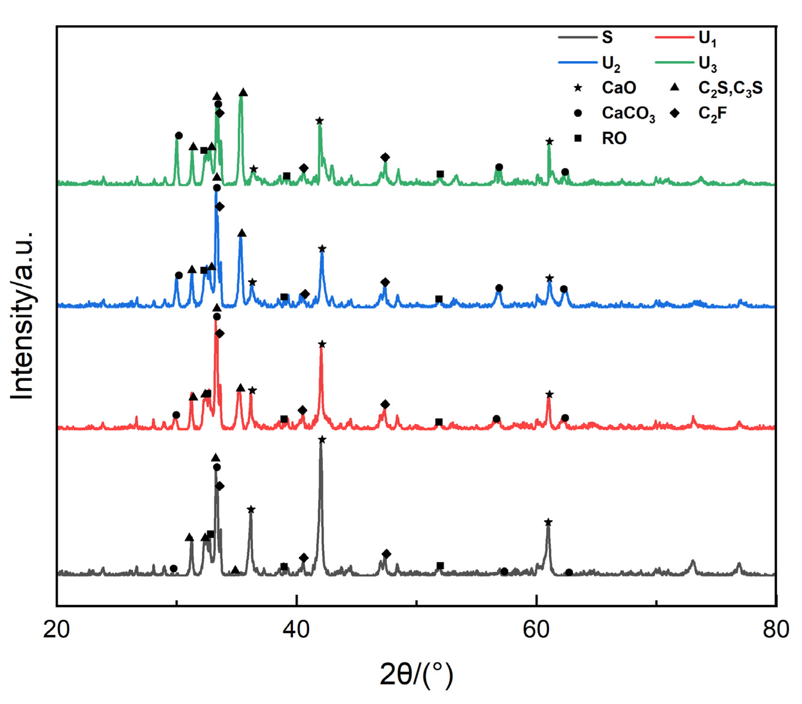
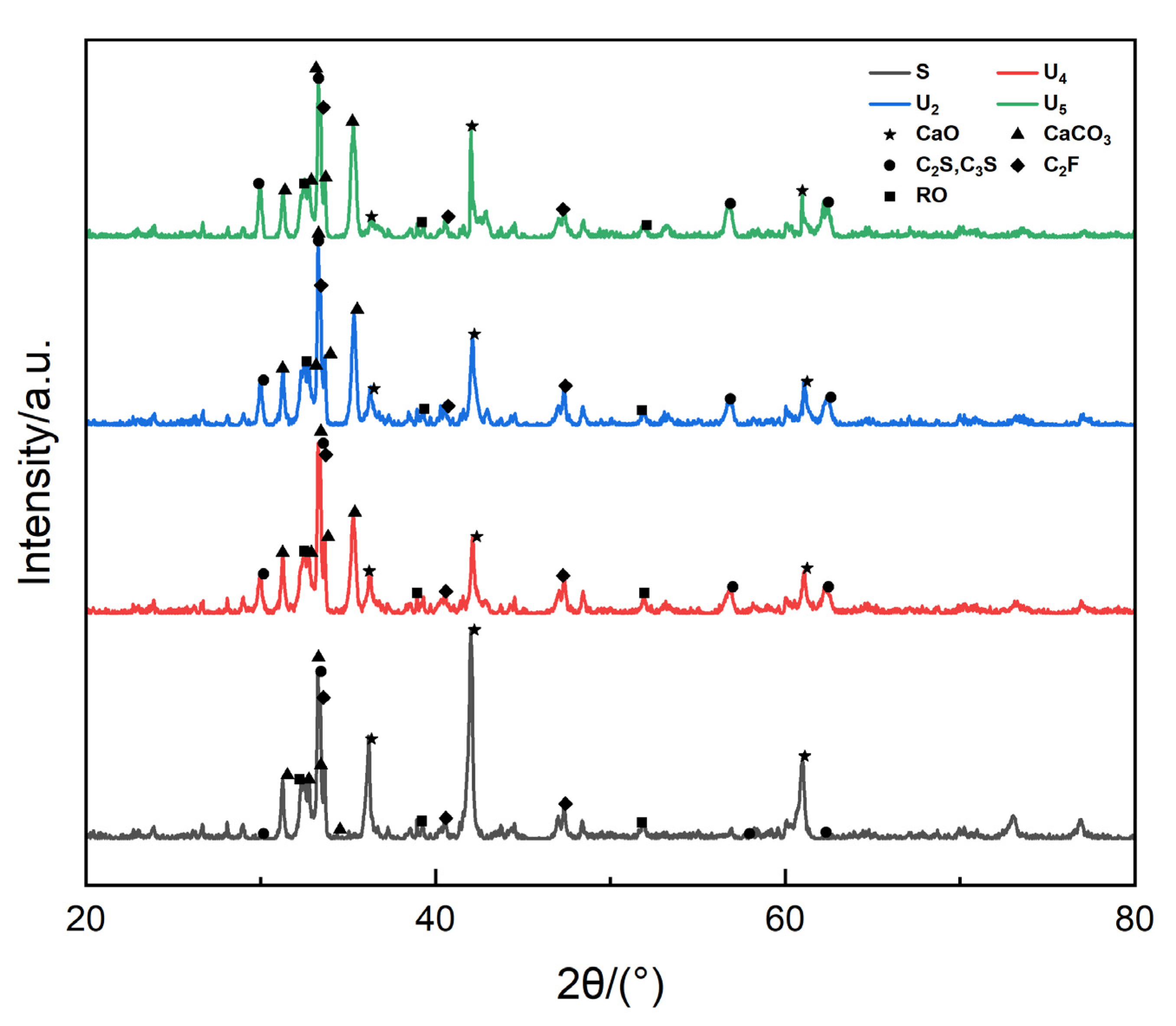
8]. However, indirect carbonation technology is too complex and is therefore not conducive to large-scale promotion and application. Therefore, in the field of direct carbonation technology, Chang et al. [9] and Bo et al. [10] used XRD for the phase analysis of steel slag before and after carbonization and found that the intensity of C2S and C3S diffraction peaks before and after the carbonization of steel slag decreased, the diffraction peaks of Ca(OH)2 and f-CaO essentially disappeared, and there were obvious CaCO3 and SiO2 diffraction peaks. Their study indicated the feasibility of conducting carbonation. By using XRD analysis, Liang [11] found that a divalent metal oxide solid solution (RO) phase and calcium ferrite (C2F) basically had no effect on the carbonation reaction, and the proper addition of H2O was beneficial to carbonation; Fang [12] studied the carbonization efficiency of steel slag minerals via QXRD and found that portlandite absorbed the greatest amount of CO2 and the carbon sequestration of γ-C2S, β-C2S, akermanite, merwinite, and cuspidine gradually decreased. Chang [13] used water to bring CO2 gas into a rotating container with steel slag, using the rotor to stir the steel slag, and achieved the CO2 capture and fixation of steel slag in water. The results showed that the maximum conversion of slag was 93.5% carbon transformation with T = 65 °C, a rotation speed of 750 r/min, and t = 30 min. Stolaroff [14] proposed a feasible technology of slag carbonation that involves spraying circulating water on a bed of ground slag, a solution containing Ca(OH)2, to collect CO2 from the air. However, the carbonation efficiency is low, the water consumption is large, the fixed cost is high, and the technology still needs to be optimized. Dong et al. [15] studied the carbonation reaction of steel slag at a temperature of 350–850 °C, a reaction time of 0.5–3 h, and a particle size of 0.074–2 mm. The results showed that the optimal reaction conditions were 700 °C, reaction time 0.5-1 h, particle size 0.18 mm, and the digestion efficiency of f-CaO can reach 90%. Peng et al. [16] conducted a study on the carbonation of hot steel slag, and the results showed that by utilizing CO2 gas as a modifier for hot steel slag, the phase composition of the steel slag improved greatly, and the amount of f-CaO reduced to less than 1%. The above relevant research indicates that CO2 gas injection in the disposal process of hot steel slag can significantly reduce the content of f-CaO during the carbonation process. However, the reaction conditions of direct carbonation are still not clear; in particular, the optimum temperatures and reaction times are quite different under pCO2 > 0.6 in CO2-H2O mixed atmosphere. The direct carbonation behavior of slag with CO2 containing water vapor still need more detailed research.
In our previous work [17], the effects of basicity and FeO content on the slag carbonation with CO2-containing water vapor has been studied and the slag basicity was optimized. In this paper, based on the previous work, with the accurate control of the mixture of CO2 and water vapor, the effects of temperatures and reaction times on steel slag carbonation behavior were studied and the reaction conditions were optimized.

2. Materials and Methods

2.1. Experimental Raw Material Preparation

Based on the general composition in various steel-making enterprises [18,19,20,21,22,23], CaO content was in the range of 38–47%, CaO/SiO2 binary basicity was in the range of 2.0–4.5, FeO content was in the range of 20–28%, MgO content was in the range of 4–7%, Al2O3 content was in the range of 1–6%, MnO content was in the range of 2–5%, and P2O5 content was in the range of 1–3%. Therefore, the components of steel slag were designed as shown in Table 1.
Since FeO and CaO are not easy to store at room temperature, the preparation is as follow:
(1)
Preparation of FeO: Fe3O4 (Sinopharm, Shanghai, China) and pure iron powder (Sinopharm, Shanghai, China) were mixed evenly in an agate mortar at a 1:1 ratio. Then, the sample was pressed into a block and put into a pure iron crucible. With a gas flow ratio of CO/CO2 = 1:1 at 500 mL/min, the sample was heated up to 1473 K and held for more than 8 h. After that, the crucible was removed quickly from the furnace, blowing nitrogen to prevent the sample from oxidizing. The sample was crushed until the size was less than 200 mesh. The results of XRD analysis are shown in Figure 1. Comparison of XRD profiles of the prepared FeO and the standard diffraction peak of FeO shows the prepared FeO can be used for experiments.
(2)
Preparation of CaO: CaO was obtained by calcining CaCO3 (Sinopharm, Shanghai, China) at 1273 K for 12 h; it was removed at 973 K, and the prepared CaO was pure enough for experiments.
Before the carbonation experiments, the slag was pre-melted. Since P2O5 is volatile at high temperature, it was replaced by Ca3P2O8 (Macklin, Shanghai, China) proportionally. An iron crucible (I.D. 40 mm, O.D. 44 mm, height 10 mm) containing approximately 150 g samples was put into the constant temperature zone of the tubular furnace. The sample was heated to 1173 K at 10 K/min and then further to 1723 K at 5 K/min to melt the sample, maintaining for more than 30 min to ensure uniform composition. The experiments were performed in an argon atmosphere with a gas flowrate of 200 mL/min and the gas purity was larger than 99.999%. After pre-melting, the slag was crushed to a size less than 200 mesh for carbonation experiments and dried in an oven at 378 K for more than 24 h.

2.2. Carbonation Experiments

The experimental apparatus is shown as Figure 2. An alumina crucible (I.D. 20 mm, O.D. 24 mm, height 50 mm) containing approximately 3 g sample was put into the furnace with 60 mL/min Ar protection. After reaching the target temperature and then holding for more than 30 min, the switchover was made from Ar gas to 20 mL/min of water vapor and 40 mL/min of CO2 to carbonate the slag. After reaching the target time, the gas was switched to 60 mL/min Ar and cooled to room temperature. The gas flowrates of CO2 and Ar were controlled by a gas mass flowmeter (Alicat, Tucson, AZ, USA, error < 0.1%), and the water vapor was controlled by a water mass flowmeter (Bronkhorst, Ruurlo, The Netherlands) to obtain the accurate flow of water into the mixing tank. Then, the mixing tank was heated at 473 K to ensure the gasification of water and all tubes were wrapped with heating wires to ensure that the channel temperature was higher than 373 K to avoid water vapor condensation. The experimental program is listed in Table 2. Experiments U1-U3 are to keep the same reaction time of 30 min and change the reaction temperatures from 873 to 1073 K; experiments U2, U4 and U5 are aimed to compare the carbonation effect of different reaction times at the same temperature of 973 K. It should be noted that in our previous work to study the effects of basicity and FeO content, the experimental conditions of U2 have been tested [17]. In the present work, based on the U2 condition, the reaction temperatures and times were adjusted for further study. The reaction temperatures were selected due to thermodynamic calculation by FactSage 7.0 software in advance, and a detailed description is given in the next section.
After experiments, the slag was also ground to a size below 200 mesh in an agate mortar. The slag was analyzed by X-ray diffractometer (Rigaku, Tokyo, Japan), using Cu target, Ka line wavelength 1.5419 A, current 40 mA, voltage 40 kV, and the scanning range was 2θ = 10–90 °. Spectra obtained from XRD were analyzed by using Jade 6.5 software. Moreover, the morphology of slag was observed by SEM-EDS (Zeiss, Oberkochen, Germany). The solid sample surface was sprayed with Au (10 mA, 120 s); a scanning electron microscope (SEM) was used to observe the mineral morphology and the energy spectrum (EDS) was used to analyze the composition. A total of 15 regional points were detected, and the measured values were averaged to improve the accuracy of the test results.

3. Results and Discussion

3.1. Thermodynamic Analysis of the Reaction

The capture of CO2 by steel slag is mainly due to the influence of f-CaO. The Gibbs free energy variation of the reactions between CaO, CO2 and H2O are listed in Table 3, and the trend of ΔrGθ with temperature is shown as Figure 3. It can be seen that the Gibbs free energy variation of the related chemical reactions at temperatures higher than 1100 K is positive, indicating that the reacting temperature should be lower than 1100 K for the carbonation reactions of steel slag to happen spontaneously. Water vapor may become a carrier for f-CaO reacting with CO2 and it may have a pseudocatalytic effect on accelerated carbonation according to relevant research [24]. Therefore, for the carbonation experiments, water vapor was introduced into the carbonation process and the reaction temperatures were selected as 873, 973 and 1073 K.

3.2. Effect of Temperature on the Carbonation Effect of Steel Slag

In order to analyze the effect of slag carbonation, the sample weights before and after the experiments were determined. Before the experiments, the weights of the empty crucible and the crucible containing the sample were determined, respectively, and the differential values were recorded as the initial sample weight as m0 (g); after the experiments, the crucible with samples was put into the oven and dried at 378 K for more than 2 h. m1 (g) is the value of the sample weight, calculated by weighing the total mass and then subtracting the quality of the empty crucible. The weight gain ratio of steel slag, w, is calculated by the following equation:
w = m 1 m 0 / m 0 × 100 %
The weight gain ratios at various temperatures are listed in Table 4. It can be seen that the three samples of U1, U2 and U3 showed weight gain after carbonation, and the weight gain rate U2 > U3 > U1, indicating that in the same case, the maximum conversion of carbonation was at 973 K.
Figure 4 shows the XRD profiles of steel slag samples without carbonation and with carbonation for 30 min at different temperatures from 873 to 1073 K. The diffraction peak of f-CaO is evident in the steel slag samples without carbonation. After the carbonation reaction occurred, the peak of f-CaO diffraction was significantly reduced; both f-CaO diffraction peaks of the uncarbonated S samples were evident, showing that the high content of f-CaO. As the carbonation proceeds, with the increase in temperature, f-CaO diffraction peaks were significantly weakened. Especially at 973 K, f-CaO diffraction peaks became very small. Meanwhile, the diffraction peak of CaCO3 was enhanced significantly. With continued heating to 1073 K, the f-CaO diffraction peak change was enhanced; meanwhile, the diffraction peak of CaCO3 was weakened. It indicated that the decomposition reaction rate of CaCO3 was accelerated at this temperature, while the carbonation reaction rate became slower. Therefore, holding the reaction time at 30 min, the suitable temperature of steel slag carbonation was 973 K. At the same time, it showed from the XRD pattern that the diffraction peaks of Ca2SiO4 and Ca3SiO5 were significantly strengthened after carbonation, while the intensity of Ca2Fe2O5 and RO (MgO, FeO and MnO, etc.) did not change much.
As for the slag morphology observation, Figure 5 shows the morphology of the carbonation products at different temperatures via SEM and the EDS map of some example detected points. It shows that the uncarbonated sample particles were large, and the size of steel slag particles was significantly reduced after carbonation. There were some granular crystals in the samples; the reason may be that in the steel slag pore, gas could diffuse to the steel slag pores under high-temperature conditions to form CaCO3, and part of the low valence state containing iron oxide or free oxide in the steel slag may react with f-CaO to form a binding state such as C2S, C3S. Therefore, it showed U2 granular diameter < U3 < U1, at a time of 30 min; with the temperature increased, the maximum conversion of carbonation was at 973 K, and when increasing temperature to 1073 K, the carbonation conversion decreased.
Figure 5 shows not only the trend of particle size, but also the carbon content trend between points a and d, which was as follows: U2 sample > U3 > U1 > S. A total of 15 points were randomly selected in all samples. The carbon content of each sample is listed in Table 5 and drawn in Figure 6. It shows that the carbon content of each point in U2 was generally higher than that of U3 and higher than that of U1, which indicated that the best temperature condition was 973 K in the present experimental conditions. The result was consistent with the analysis of weight gain ratio and XRD determination.

3.3. Effect of Carbonation Time on the Carbonation Effect of Steel Slag

Based on the optimum reaction temperature of 973 K, the reaction times were selected from 15 to 45 min. As seen from Table 6, the three samples of U4, U2 and U5 showed weight gain after carbonation, and the weight gain ratio U2 > U5 > U4, indicating that the best reaction time was 30 min under the condition of 973 K carbonation.
Figure 7 shows the XRD pattern of the steel slag of each treatment group. It shows that the diffraction peak of f-CaO was evident in the steel slag samples without carbonation. After the carbonation reaction occurred, the f-CaO diffraction peak was significantly reduced. Under the same reaction temperature (973 K), comparing the no-carbonation sample S, the f-CaO diffraction peak under a carbonation time of 15 min was noticeably reduced; increasing the time to 30 min, f-CaO diffraction peaks became very small. Meanwhile, the diffraction peak of CaCO3 was also significantly enhanced, while increasing carbonation for 45 min, the f-CaO diffraction peak change was enhanced. Meanwhile, the diffraction peak of CaCO3 was slightly weakened. It indicated that 30 min was long enough for carbonation. An excessively long reaction time may slightly reduce the content of CaCO3. Therefore, the maximum conversion under the condition of 973 K carbonation is 30 min.
Figure 8 shows the slag morphology of the carbonation products at different temperatures by SEM and the EDS map of the corresponding points. It shows that the S uncarbonated sample particles were large, and the steel slag particles were significantly reduced after the carbonation reaction; moreover, the particle size trend was U2 granular diameter < U5 < U4, indicating that the carbonation effect at 30 min was better than that of 15 min at 973 K, and the reaction effect was decreased as the carbonation time increased to 45 min.
From the results of EDS analysis in Figure 8, it was shown that the carbon content trend between the points a and d was that of U2 samples > U5 > U4 > S. A total of 15 points were randomly selected in the sample. The carbon content of each sample is shown in Table 7 and shown in Figure 9. It can be seen that the carbon content of each point in sample U2 is generally higher than that of U5, higher than U4 and higher than uncarbonated S number, indicating that the reaction time with the maximum conversion efficiency is 30 min for 973 K in the present experimental conditions. The result was consistent with the analysis of weight gain ratio and XRD determination.
Based on the above analysis, the summarized carbonation effect under different conditions is listed in Table 8. Therefore, the optimized conditions of slag carbonation were a reaction temperature of 973 K and reaction time of approximately 30 min. When the temperature was low, the reaction rate was low, which meant that the slag carbonation conversion was low. When the temperature was too high, the formed CaCO3 was relatively dense, and the gas diffusion was low, which was not conducive to the reaction. Therefore, the suitable temperature was 973 K. As for the reaction time, 30 min was enough to obtain the maximum conversion of carbonation in the present work.

4. Conclusions

The influences of the carbonation temperature and time on the steel slag carbonate in CO2 and water vapor mixed gas were studied by mass balance analysis, XRD analysis, and SEM-EDS analysis. The observed results and subsequent discussion are summarized as below.
Based on the thermodynamic analysis, a temperature of less than 1100 K is more appropriate for carbonation reactions. The carbonation of steel slag increases as the temperature increases within a certain range. Under the condition of the mixture of carbon dioxide and water vapor as the carbonation atmosphere for 30 min, the carbonation efficiency at 973 K was shown to be better than that of 873 K; additionally, the carbonation conversion was higher, and the efficiency of further heating to 1073 K decreased. At 973 K, the effect of carbonate formation for 30 min was better than that for 15 min, and when the carbonation time was increased to 45 min, the carbonation efficiency decreased. Moreover, in the range of 873–1073 K and under a reaction time of 15–45 min, the carbonation process can make the microstructure of steel slag more compact and reduce the particle size.

Author Contributions

Conceptualization, Y.F. and X.H.; methodology, W.L.; validation, Y.F.; formal analysis, W.L.; investigation, W.L.; data curation, W.L.; writing—original draft preparation, Y.F. and W.L.; writing—review and editing, X.H.; supervision, X.H.; funding acquisition, Y.F. All authors have read and agreed to the published version of the manuscript.

Funding

The author (Yuewen Fan) was funded to study this work by Postdoctoral Fellowship Program of CPSF, grant number GZC20230242.

Data Availability Statement

The raw data supporting the conclusions of this article will be made available by the authors on request.

Conflicts of Interest

The authors declare no conflicts of interest.

References

  1. Liu, C.; Peng, B.; Xia, C.; Yue, C.; Wu, L. Research progress in the utilization and stabilization technology of steel slag. Conver. Util. Min. Res. 2018, 6, 145–150. [Google Scholar]
  2. Shen, H.; Forssberg, E. An overview of recovery of metals from slags. Waste Manag. 2003, 23, 933–949. [Google Scholar] [CrossRef] [PubMed]
  3. Zhang, F.; Mo, L.; Deng, M. The influence of carbonization curing on the strength and volume stability of steel slag concrete. J. Chin. Ceram. Soc. 2016, 44, 640–646. [Google Scholar]
  4. Huijgen, W.J.; Witkamp, G.; Comans, R.N. Mineral CO2 sequestration by steel slag carbonation. Environ. Sci. Technol. 2005, 39, 9676–9682. [Google Scholar] [CrossRef]
  5. Boot-Handford, M.E.; Abanades, J.C.; Anthony, E.J.; Blunt, M.J.; Brandani, S.; Dowell, N.N.; Fernandez, J.R.; Ferrari, M.C.; Gross, R.; Hallett, J.P.; et al. Carbon capture and storage update. Energy Environ. Sci. 2014, 7, 130–189. [Google Scholar] [CrossRef]
  6. Morandeau, A.E.; Mickaël, T.; Patrick, D. Investigation of the carbonation mechanism of CH and C-S-H in terms of kinetics, microstructure changes and moisture properties. Cem. Concr. Res. 2014, 56, 153–170. [Google Scholar] [CrossRef]
  7. Chang, J.; Wang, S.; Shao, Y. Manufacture of electric arc furnace slag aggregate and concrete through carbonation curing. J. Chin. Ceram. Soc. 2007, 35, 1264–1269. [Google Scholar]
  8. Pan, S.Y.; Adhikari, R.; Chen, Y.; Li, P.; Chiang, P. Integrated and innovative steel slag utilization for iron reclamation, green material production and CO2 fixation via accelerated carbonation. J. Clean. Prod. 2016, 137, 617–631. [Google Scholar] [CrossRef]
  9. Chang, J.; Wu, H. Study on the carbonization mechanism of steel slag. J. Chin. Ceram. Soc. 2010, 38, 1185–1190. [Google Scholar]
  10. Bo, P.; Zhou, Z.; Xu, H. Utilization of carbonated and granulated steel slag aggregate in concrete. Constr. Build. Mater. 2015, 84, 454–467. [Google Scholar]
  11. Liang, X. Study on the Relationship Between Carbide and Hydration of Steel Slag and Cement. Master’s Thesis, University of Jinan, Jinan, China, 2012. [Google Scholar]
  12. Fang, Y.; Zhang, T.; Chang, J. Accelerated carbonization of different minerals of steel slag. J. Chin. Electr. Microsc. Soc. 2015, 34, 464–469. [Google Scholar]
  13. Chang, E.E.; Pan, S.Y.; Chen, Y.H.; Tan, C.S.; Chiang, P.C. Accelerated carbonation of steelmaking slags in a high-gravity rotating packed bed. J. Hazard. Mater. 2012, 97, 227–228. [Google Scholar]
  14. Stolaroff, J.K.; Lowry, G.V.; Kerth, D.W. Using CaO- and MgO-rich industrial waste streams for carbon sequestration. Energy Convers. Manag. 2005, 46, 687–699. [Google Scholar] [CrossRef]
  15. Dong, X. Preliminary experiments on fast absorption of CO2 by steel slag of converter. Steelmaking 2008, 24, 29–32. [Google Scholar]
  16. Peng, B.; Yue, C.; Huang, S.; Zhang, M.; Guo, M.; Hu, T. CO2 modification and thermodynamic property of hot steel slag. Environ. Eng. 2015, 33, 100–102+69. [Google Scholar]
  17. Liang, W.; Fan, Y.; Hu, X.; Chou, K. The influence of composition on direct carbonation of steel slag. J. Mater. Metall. 2024; accepted. [Google Scholar]
  18. Wu, L.; Zhou, Y.; Wang, J.; Wang, H.; Dong, Y. Study on the grindability of steelmaking slag modified by silica. Steelmaking 2014, 30, 62–65. [Google Scholar]
  19. Shu, Q.; Liu, Y. Effects of basicity, MgO and MnO on mineralogical phases of CaO-FeOx-SiO2-P2O5 slag. Ironmak. Steelmak. 2018, 45, 363–370. [Google Scholar] [CrossRef]
  20. Zhou, H.; Hu, L.; Wan, J.; Yang, R.; Yu, X.; Li, H.; Chen, J.; Wang, L.; Lu, X. Microwave-enhanced catalytic degradation of p-nitrophenol in soil using MgFe2O4. Chem. Eng. J. 2016, 284, 54–60. [Google Scholar] [CrossRef]
  21. Reddy, A.S.; Pradhan, R.K.; Chandra, S. Utilization of basic oxygen furnace (BOF) slag in the production of a hydraulic cement binder. Int. J. Miner. Process. 2006, 79, 98–105. [Google Scholar] [CrossRef]
  22. Malvoisin, B.; Brunet, F.; Carlut, J.; Montes-Hernandez, G.; Findling, N.; Lanson, M.; Vidal, O.; Bottero, J.; Goffe, B. High-purity hydrogen gas from the reaction between BOF steel slag and water in the 473–673 K range. Int. J. Hydrogen Energy 2013, 38, 7382–7393. [Google Scholar] [CrossRef]
  23. Irawati, I.; Djakfar, L.; Arifin, Z.M. Comparison of the moisture resistance of a steel-slag stone mastic asphalt mixture modified with Ca(OH)2. East.-Eur. J. Enterp. Technol. 2023, 6, 62–70. [Google Scholar] [CrossRef]
  24. Ooi, B.K.H.; Marek, E.J. Kinetics of CO2 capture with calcium oxide during direct air capture in a fluidized bed. Energy Fuels 2024, 38, 22290–22297. [Google Scholar] [CrossRef] [PubMed]
Figure 1. The XRD profile of the FeO.
Metals 15 00237 g001
Figure 2. The experimental apparatus. Red line: heating tube; red rectangle: heating tank.
Metals 15 00237 g002
Figure 3. ΔrGθ-T relation curve of reactions (1)–(3); green dotted line: ΔrGθ = 0.
Metals 15 00237 g003
Figure 4. XRD profiles corresponding to steel slag samples with different carbonation temperatures. S: no carbonation; U1: 873 K; U2: 973 K; U3: 1073 K.
Metals 15 00237 g004
Figure 5. SEM morphology of carbonated samples at different temperatures and EDS profiles of the corresponding points. (a) Sample S before carbonation; (b) sample U1 after carbonation; (c) sample U2 after carbonation; (d) sample U3 after carbonation.
Metals 15 00237 g005
Figure 6. Carbon content and average values at different temperatures.
Metals 15 00237 g006
Figure 7. XRD profiles corresponding to steel slag samples with different carbonation times, S: no carbonation; U2: 30 min; U4: 15 min; U5: 45 min.
Metals 15 00237 g007
Figure 8. SEM morphology of carbonated samples at different times and EDS profiles of corresponding points. (a) Sample S before carbonation; (b) sample U4 after carbonation; (c) sample U2 after carbonation; (d) sample U5 after carbonation.
Metals 15 00237 g008
Figure 9. Carbon content at different points at different times.
Metals 15 00237 g009
Table 1. Chemical composition of the slag (wt%).
CompositionCaOSiO2FeOMgOAl2O3MnOP2O5
Mass fraction/%42.0018.0026.005.003.004.002.00
Table 2. Experimental program.
Sample/No.T/Kt/min
U187330
U297330
U3107330
U497315
U597345
Table 3. Reaction equation and ΔrGθ of reaction.
NumberReaction EquationΔrGθ/(J·mol−1)
1CaO(s) + CO2(g) = CaCO3(s)−161,300 + 137.23 T
2CaO(s) + H2O(g) = Ca(OH)2(s)−106,687 + 135.37 T
3Ca(OH)2(s) + CO2(g) = CaCO3(s) + H2O(g)−54,613 + 1.68 T
Table 4. Sample mass and weight gain ratio.
Sample NumberCrucible Mass/gCrucible and Sample Mass Before the Experiment/gm0/gCrucible and Sample Mass After the Experiment/gm1/gw/%
U136.443439.44753.004139.46953.02610.0073
U238.804041.79672.992741.83793.03390.0138
U337.683540.68453.001040.71123.02770.0090
Table 5. Carbon content at different points at various reaction temperatures (wt%).
Detection Points123456789
S7.85.43.95.37.22.765.33.4
U18.47.16.98.47.75.66.87.08.0
U29.79.911.813.19.116.913.110.718.5
U38.711.79.811.99.813.511.79.911.7
Detection Points101112131415MaxMinAverage Value
S7.96.24.04.25.76.07.92.75.4
U16.89.17.213.18.111.113.15.68.1
U222.89.87.315.213.020.022.87.313.4
U38.97.211.78.812.511.613.57.210.6
Table 6. Sample mass and weight gain ratio under different reaction times.
Sample NumberCrucible Mass/gCrucible and Sample Mass Before the Experiment/gm0/gCrucible and Sample Mass After the Experiment/gm1/gw/%
U437.416840.41662.999840.43393.01710.0058
U238.804041.79672.992741.83793.03390.0138
U533.274736.27422.999536.29743.02270.0077
Table 7. Carbon content at different points at various reaction times (wt%).
Detection Points123456789
S7.85.43.95.37.22.765.33.4
U48.37.99.27.1712.48.37.619.4
U29.79.911.813.19.116.913.110.718.5
U57.28.910.31310.212.311.98.915.5
Detection Points101112131415MaxMinAverage Value
S7.96.244.25.767.92.75.4
U411.57.76.678.914.619.479.6
U222.89.87.315.2132022.87.313.4
U514.17.310.214.914.21815.57.211.8
Table 8. The carbon content of steel slag under various conditions (wt%).
Carbon Content (%)No-Carbonation873 K973 K1073 K
None5.4---
15 min--9.6-
30 min-8.113.410.6
45 min--11.8-
Disclaimer/Publisher’s Note: The statements, opinions and data contained in all publications are solely those of the individual author(s) and contributor(s) and not of MDPI and/or the editor(s). MDPI and/or the editor(s) disclaim responsibility for any injury to people or property resulting from any ideas, methods, instructions or products referred to in the content.

