Abstract
Lattice structures are widely used in the aerospace and biomedical fields, due to their lightweight, high specific strength, large specific surface area, good biocompatibility, etc. However, the balancing of the weight and the mechanical properties remains a challenge in designing lattice structures. Combining experiments and simulations, the present work first designs and evaluates the mechanical properties of uniform and gradient topology-optimized Ti-6Al-4V lattices with the same overall porosity of 84.27%, employing finite element simulations. Then, laser powder bed fusion technology is used to fabricate the uniform and gradient Ti-6Al-4V lattices, and their compressive performance is tested. The results indicate that, under longitudinal compression, the gradient lattice structure exhibits good layer-by-layer collapse deformation behavior, achieving better comprehensive performance than the uniform lattice structure. While under horizontal compression, the deformation behavior of the gradient lattice structure is similar to that of the uniform lattice structure, and the deformation is mostly randomly distributed. The cumulative energy absorption of the gradient lattice structure increased by approximately 20% compared with that of the uniform lattice structure. The results provide a technical basis for the integrated design of structural and functional components for aerospace applications.
1. Introduction
Titanium and its alloys have been widely used in both aerospace and biomedical applications due to their excellent properties such as high strength, excellent fatigue resistance, corrosion resistance, and outstanding biocompatibility [1,2,3]. Compared with traditional energy-absorbing materials, the specific energy absorption of titanium alloys is relatively inadequate [4,5]. By adopting a lattice matrix structure, the energy absorption effect can be effectively improved to achieve a specific energy absorption effect that is substantially better than that of steel materials [6].
Lattice material is a new type of engineering material that combines functional and structural properties. It has the characteristics of light weight, large specific surface area, high specific strength, low thermal conductivity, and impact resistance and is widely used in fields such as aerospace, biomedicine, and petrochemicals [7,8,9]. However, balancing the weight, thermal insulation, and mechanical properties of lattice materials is still a challenge when designing lattice materials (structures) for some special applications. A gradient lattice structure refers to a lattice structure in which the pore size and arrangement change according to a certain pattern with depth. It has many advantages such as improved residual stress distribution, enhanced thermal properties, improved fracture toughness, and reduced stress intensity factor [10]. Its excellent structural characteristics can effectively improve the energy absorption rate and mechanical properties of titanium alloys. Topology optimization is an advanced computational technique that optimizes material layout within a predefined design domain to meet specific constraints and achieve performance optimization, especially suitable for the design of complex porous lattice structures [11]. Topology optimization systematically analyzes and adjusts the number, size, shape, and location of holes in a structure in order to maximize the overall performance of the structure while achieving a lightweight design [12,13,14]. Within a certain range, the volume fraction of topology-optimized structures is proportional to their moduli, and, thus, structures with a higher volume fraction exhibit greater strength and superior fatigue life [15,16]. In addition, topology-optimized structures can effectively reduce the stress concentration phenomenon and, thus, inhibit the emergence of fatigue cracks, which significantly improves the reliability and durability of the structures in long-term use [13,17].
Laser powder bed fusion (LPBF) technology, as a popular additive manufacturing process, is based on three-dimensional digital models [18,19,20,21]. These models are sliced into two-dimensional plane coordinates with high-precision parameters. Using a high-intensity laser as the energy source, the laser beam melts the powder layer by layer through heat (near-infrared light with a wavelength of approximately 1064–1080 nm), achieving rapid processing. The material then cools and solidifies, accumulating to form three-dimensional (3D) parts that meet the dimensional requirements [22,23,24]. Liu et al. [25] used LPBF to fabricate topologically optimized porous titanium structures, which exhibited high plasticity and excellent fatigue resistance, significantly reducing the fatigue crack propagation rate and extending their fatigue life. Chen et al. [26] investigated the effect of microstructure on the fatigue behavior of graded porous titanium alloys formed by LPBF, gaining insights into the relationship between fatigue performance and microstructure. They found that differences in gradient density distribution had a significant impact on fatigue performance. Hu et al. [27] used LPBF to investigate the microstructure and mechanical properties of porous titanium implants. It was found that the performance along the scanning direction was slightly better than that along the forming direction, and that the lattice materials with a porosity of 60%~80% had superior compressive strength and elastic modulus. Ren et al. [28] used LPBF to fabricate a hexagonal-body-centered (HBC) lattice structure, and the experiments showed that the HBC lattice structures produced by LPBF not only had good formability but also demonstrated excellent mechanical properties and energy absorption capacity.
Despite the previous intensive investigations on uniform lattice structures, gradient lattice structures have been much less covered. Indeed, both new deformation mechanisms and mechanical properties are present in gradient lattice structures. In this work, we focus on the enhanced compressive property of gradient lattices compared with uniform lattices with the same overall porosity, primarily aiming at the applications of complex lattice structures in the aerospace field in which the mechanical properties require further improvement. Moreover, we employed as-print samples because, in certain circumstances, subsequent hot isostatic pressing or heat treatment is not applicable.
2. Experimental Procedures and Programs
2.1. Experimental Materials
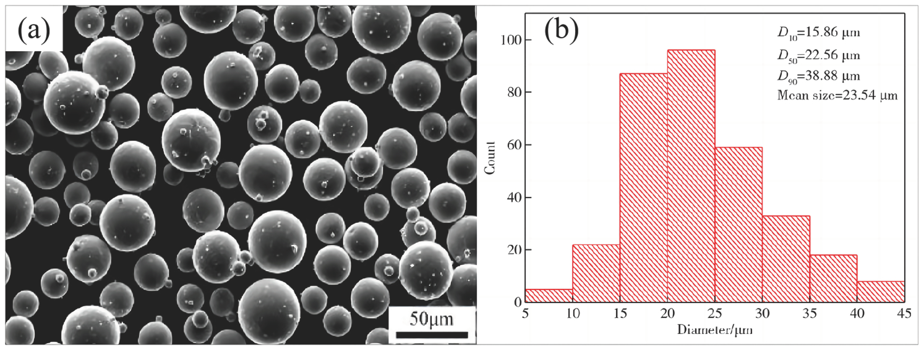
Spherical gas-atomized pre-alloyed Ti-6Al-4V (TC4) powder (provided by Aerospace Seahawk (Harbin) Titanium Industry Co., Ltd., Harbin, China) having an average size ranging from 15 to 53 μm was used in this study (Figure 1a). The specific parameters of the Ti-6Al-4V powder are shown in Table 1, and the average sphericity of the Ti-6Al-4V powder is about 0.96 (Sphericity is the ratio of the surface area of a sphere with the same volume as the particle to the actual surface area of the particle. It is a dimensionless quantity), as detected by the National Nonferrous Metals and Electronic Materials Analysis and Testing Center of National Standard (Beijing) Inspection and Certification Co. (Beijing, China). Figure 1 shows the typical morphology of TC4 powder used for developing the lattice structures by using an LPBF printer (AmPro Innovations Technology Co., Ltd., Suzhou, China). Furthermore, the spherical shape of the powder particles with a smooth surface and their size range (15 to 53 micrometers) both met the LPBF printer’s feed requirements.
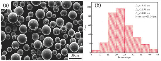
Figure 1.
(a) SEM image of initial TC4 powder; (b) powder particle size distribution chart.

Table 1.
Chemical composition (wt%) of TC4 powder metallurgy titanium alloy.
2.2. Lattice Structure Design and Fabrication
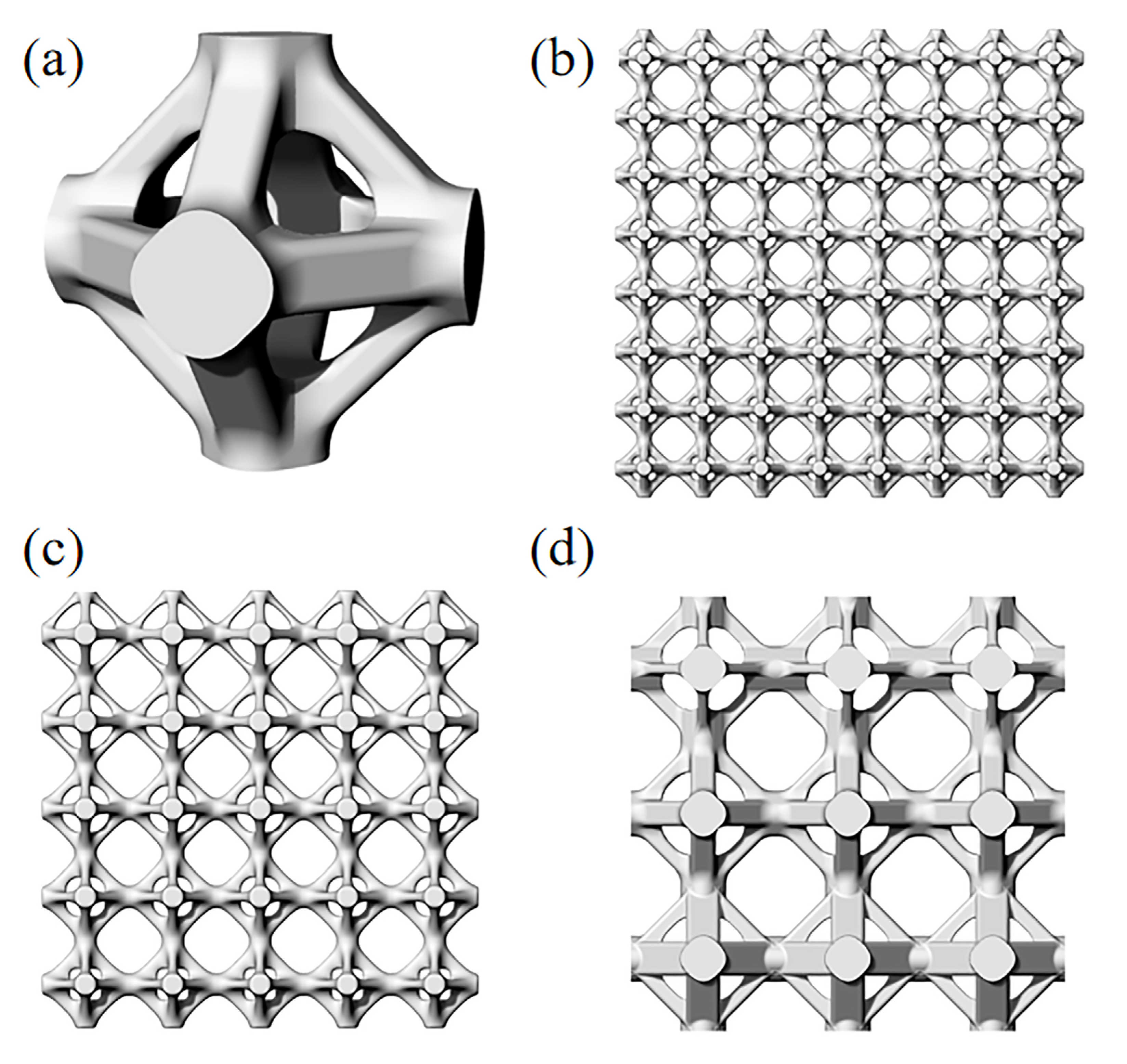
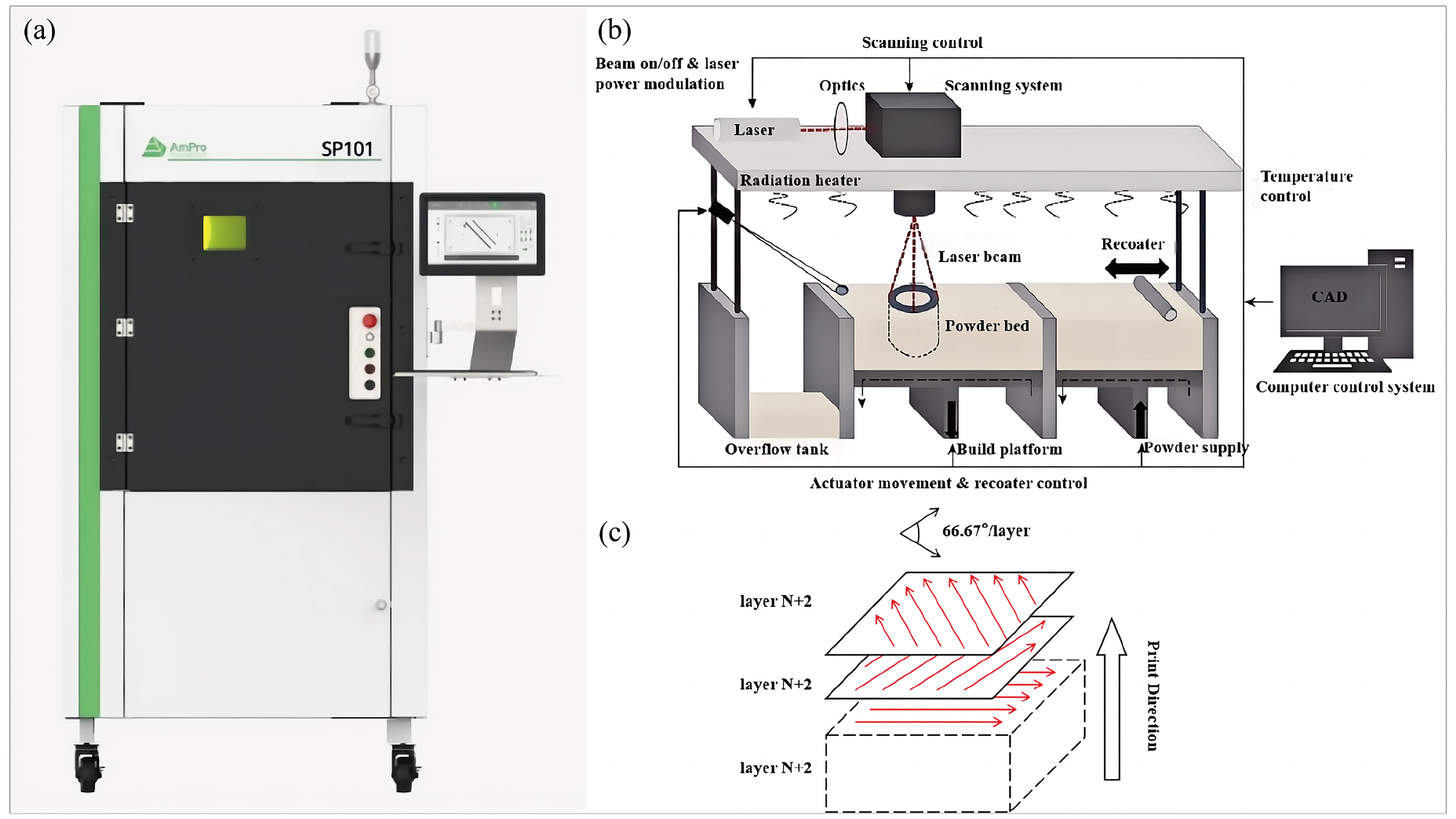
Currently, the topologically optimized BCC lattice structure has been well investigated and exhibits superior mechanical properties [17,29,30]. Our research focuses on exploring the performance and behavior of lattice structures during the LPBF forming process. The experiments utilized a combination of Solidworks (Dassault Systèmes (Shanghai) Co., Ltd., Shanghai, China) and Rhino Grasshopper (Robert McNeel & Associates, Seattle, WA, USA) to design three topology optimization-based BCC uniform lattice structures and gradient lattice structures all with an average porosity of 84.32%, as shown in Figure 2. Solidworks (https://www.solidworks.com/, accessed on 12 September 2024) is used to construct lattice unit cells and generate uniform lattice structures through linear arrays. Due to the varying interlayer densities in the gradient lattice structure, Rhino Grasshopper (https://www.rhino3d.com/learn/?query=kind:%20grasshopper, accessed on 12 September 2024) is used to generate the gradient lattice structure by defining the number of layers, along with the porosity of the top and bottom layers, using a linear relationship. Lattice unit cells with different densities are obtained by adjusting the rod width, in which the smallest unit cell size is 3.3 mm × 3.3 mm × 3.3 mm, the maximum rod width is 0.80 mm, and the minimum width is 0.25 mm. Consequently, the porosity of the unit cell structures ranges from a minimum of 80.63% to a maximum of 88.01%. The gradient lattice with varying porosity gradients is generated using arrays and combinations, with the porosity gradient increasing from 1.05% at G-A to 3.69% at G-C. The experiment employed the SP101 (AmPro Innovations, AmPro Innovations Technology Co., Ltd., Suzhou, China) LPBF system (Figure 3a). Using this equipment, Ti-6Al-4V lattice structure specimens were prepared. The process flow for this preparation is illustrated in Figure 3b. A circular TC4 substrate with a diameter of Φ100 mm was selected for the test, and a stripe scanning strategy was adopted. The laser path rotation angle was 66.67°; the stripe width was 10 mm; and the stripe overlap was 0.08 mm (Figure 3c). Titanium alloy has an extremely strong oxidation capability. To prevent oxidation during the experiment, the entire forming process was conducted in an inert gas environment. Argon gas was selected as the protective gas, and the oxygen content was controlled to be below 900 ppm to reduce unnecessary contamination. After printing was completed, wire cutting was used to remove the sample from the substrate. To remove any unmelted powder from the samples, all the specimens were cleaned by ultrasonic oscillation in an ultrasonic cleaning machine with anhydrous ethanol for 15 min. After cleaning and drying, the samples were stored in sealed bags.
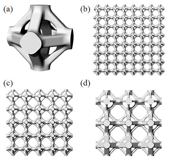
Figure 2.
(a) Topology-optimized structural single-cell model; (b) 8 × 8 × 8 gradient lattice structure G-A; (c) 5 × 5 × 5 gradient lattice structure G-B; (d) 3 × 3 × 3 gradient lattice structure G-C.
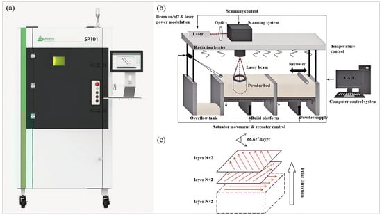
Figure 3.
(a) Physical diagram of the device; (b) workflow diagram; (c) scanning strategy.
The laser energy input into the powder bed in LPBF is controlled by the laser power P (W), scanning speed v (mm/s), scanning spacing s (mm), and layer thickness t (mm). It is typically expressed as a function of laser energy density Ed (J/mm3) and used for parameter optimization [31,32], but there are certain limitations.
The processing parameters were obtained after the parameter optimization by using the Doehlert matrix method [33,34], with a laser power of 180 W, scanning speed of 1000 mm/s, energy density range of 66.67 J/mm3, laser spacing of 0.09 mm, and layer thickness of 30 μm. The samples fabricated using the optimal process parameters are shown in Figure 4. The microstructure of the as-fabricated samples is mainly composed of α grains and acicular metastable α′ martensites (for details, please refer to our previous works [35,36]).
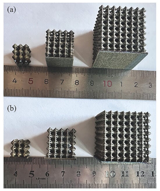
Figure 4.
Samples prepared by LPBF: (a) uniform lattice; (b) gradient lattice.
2.3. Quasi-Static Compression
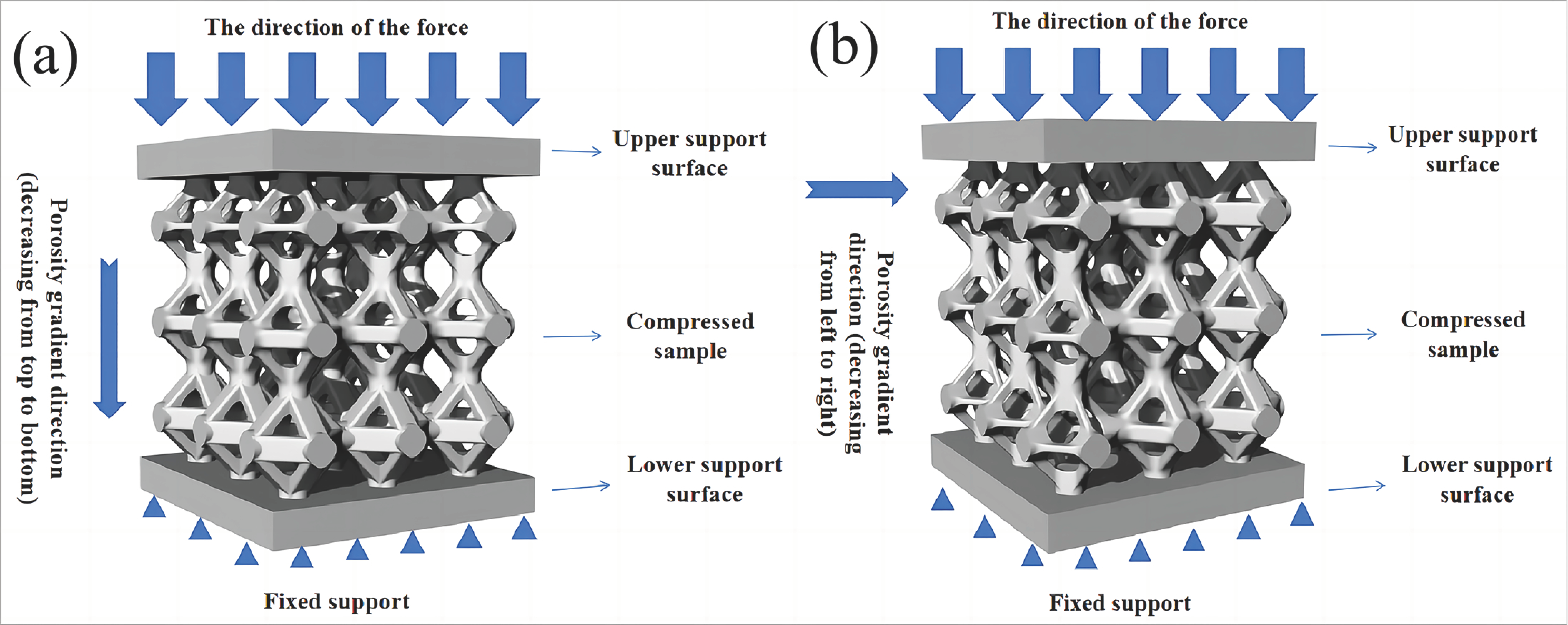
Based on the ISO 13314-2011 standard [37,38], the samples were compressed using a Zwick/Roell Z100 universal testing machine from Ulm, Germany at a speed of 1.0 mm/min, with a maximum experimental force of 100 kN. The principle of the compression test is shown in Figure 5. Compression tests were conducted on different uniform lattice structures and gradient lattice structures, with at least five compression tests for each sample. The section morphology was observed using a scanning electron microscope (SEM, Zeiss SUPRA55, Oberkochen, Germany) under the secondary-electron-imaging mode (SEI), and its specific deformation mechanism and fracture surface microstructure were analyzed. The experimental stress–strain curves were averaged from multiple tests. The energy absorption was then calculated according to the stress–strain curves.
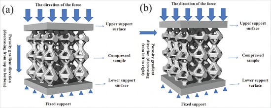
Figure 5.
Schematic diagram of compression test: (a) longitudinal compression; (b) transverse compression.
2.4. Finite Element Analysis
Before conducting the static compression experiment, numerical simulation analysis was carried out to predict the mechanical properties of a Ti-6Al-4V lattice structure designed based on topology optimization. The compression model mainly consists of three parts, with the middle part being the lattice structure, and the upper and lower sides being rigid planes, respectively. The lower rigid plane is fixed with constraints, and the compression process of the pressing plate is simulated in the explicit dynamics module, in which the upper plate is pressed down at a speed of 1.0 mm/min. The structural model employs Cartesian grid elements to mesh the complex lattice structure, with a grid size of 0.3 mm [39,40]. The dynamic friction coefficient between the structure and the surfaces of the lower and upper supports is 0.15, and the static friction coefficient is 0.25. The elastic properties of the material are set with an elastic modulus of 110 GPa and a Poisson’s ratio of 0.33 [41]. An isotropic hardening constitutive model is adopted in this study, and the Johnson–Cook failure model is used for the fracture failure model [42,43].
3. Results and Discussion
3.1. Finite Element Simulations
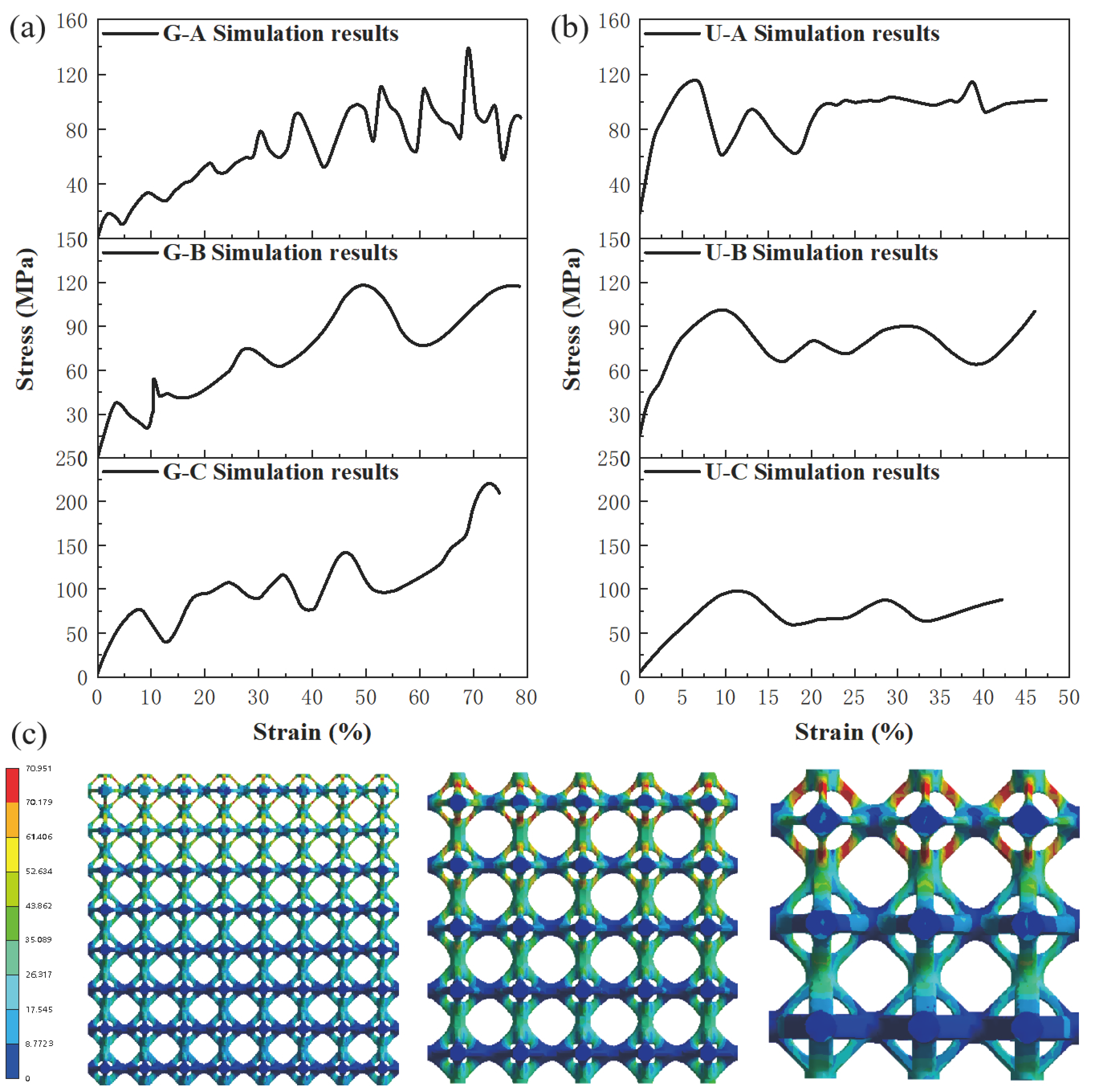
To validate the feasibility of the experiment, this study used finite element simulation to predict the deformation within the compressed samples. Due to the lack of an anisotropic failure model for the present system, an isotropic failure model was employed to estimate the stress and strain distribution. As shown in Figure 6a,b, the gradient lattices exhibit a distinct stress–strain behavior compared with the uniform lattices. The layer-by-layer failure behavior results in an overall uphill stress–strain relation. During the compression process after the first failure, the stress rises again due to the densification of the first layer. In contrast, for the uniform lattices, the stress decreases after the peak and only reaches a higher value when the sample is finally completely densified. The corresponding stress distribution is shown in Figure 6c. The simulation results demonstrate that the gradient lattices possess better compression characteristics than the uniform lattices.

Figure 6.
Finite-element-simulated compressive stress–strain curves and stress distribution: (a) gradient lattice longitudinal compressive load; (b) uniform lattice compressive load; (c) stress distribution.
3.2. Deformation Behavior and Failure Mechanisms
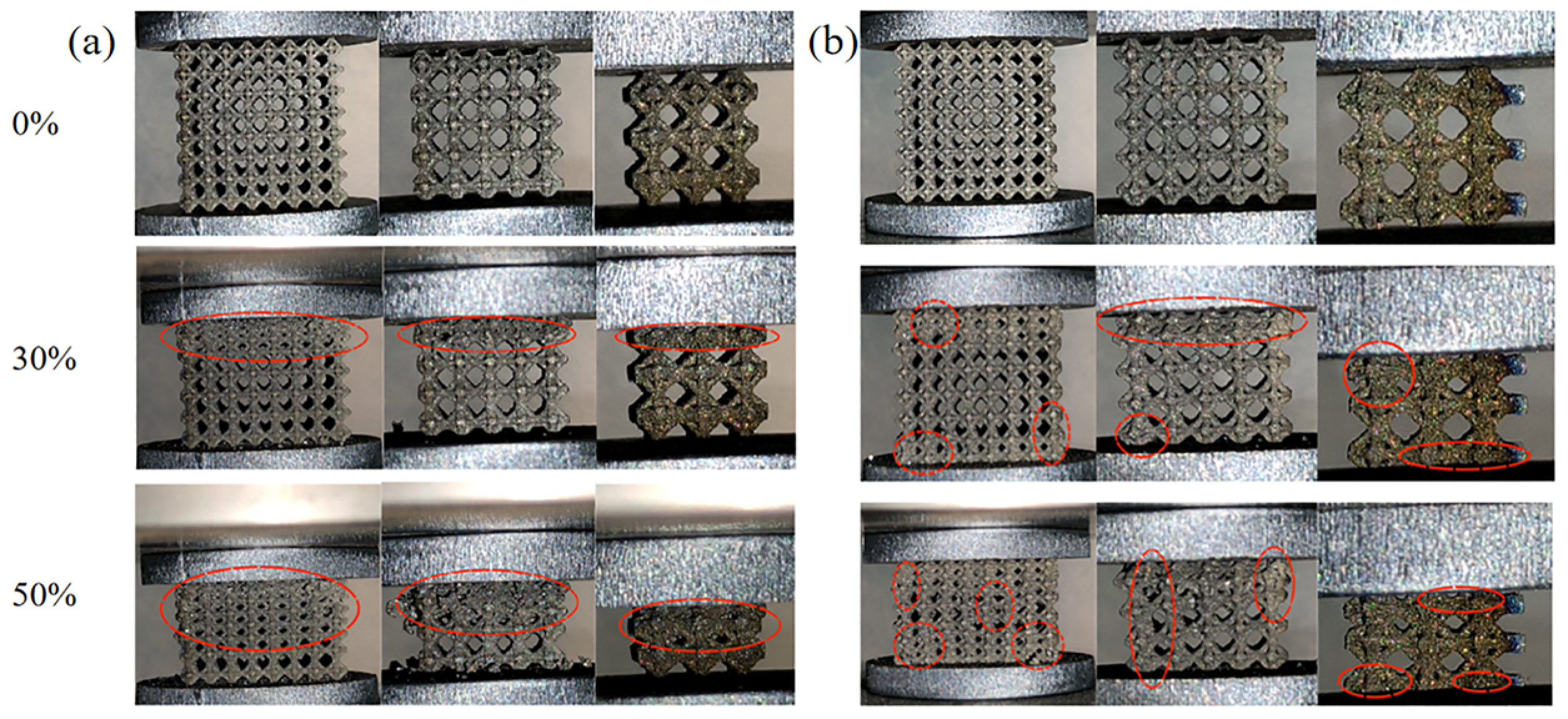
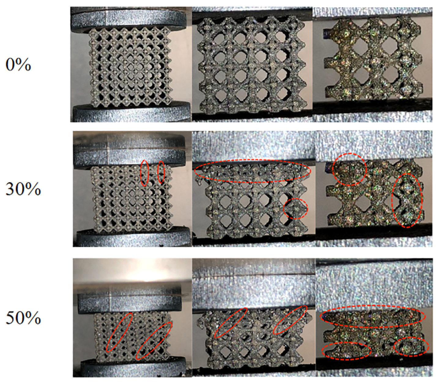
During the longitudinal compression process, the layer with lower relative density will preferentially withstand higher stress and, thus, undergo collapse deformation behavior, as shown in Figure 7a (the percentage on the left side represents the degree of deformation). As the relative density increases, the stress value gradually increases. Other layers gradually collapse as deformation progresses, and the overall structure exhibits a clear layer-by-layer collapse behavior. Compared to the layer-by-layer collapse behavior during longitudinal compression, the deformation of the uniform lattice structure did not change in sequence, as shown in Figure 7b. The deformation of the uniform lattice structure exhibited a random distribution, starting from any layer and then randomly spreading to another layer. The overall structure gradually compressed, expanded, and flattened, ultimately leading to the complete failure of the sample. Since there is no difference between transverse and longitudinal loading for a uniform lattice, it was also found that the deformation behavior of the gradient lattice structure was similar to that of the uniform lattice structure during compression under transverse loading (as shown in Figure 8, the percentage on the left side represents the degree of deformation). This deformation mechanism is consistent with the failure mechanism of gyroid structures reported by Polley et al. [44] and Li et al. [45]. Based on these conclusions, we can obtain the desired properties by applying forces in different loading directions. For example, when subjected to longitudinal loads, the lattice structure can enhance the energy absorption of the structure and, thus, provide greater strain protection; when subjected to transverse loads, the lattice structure can be used for lightweight structures or to simulate tissue density in the medical field.
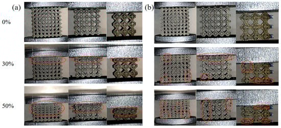
Figure 7.
Longitudinal compression deformation of different lattice structures: (a) gradient lattice structure; (b) uniform lattice structure.
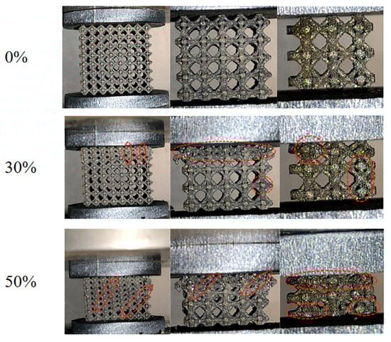
Figure 8.
Transverse compression deformation of gradient lattice.
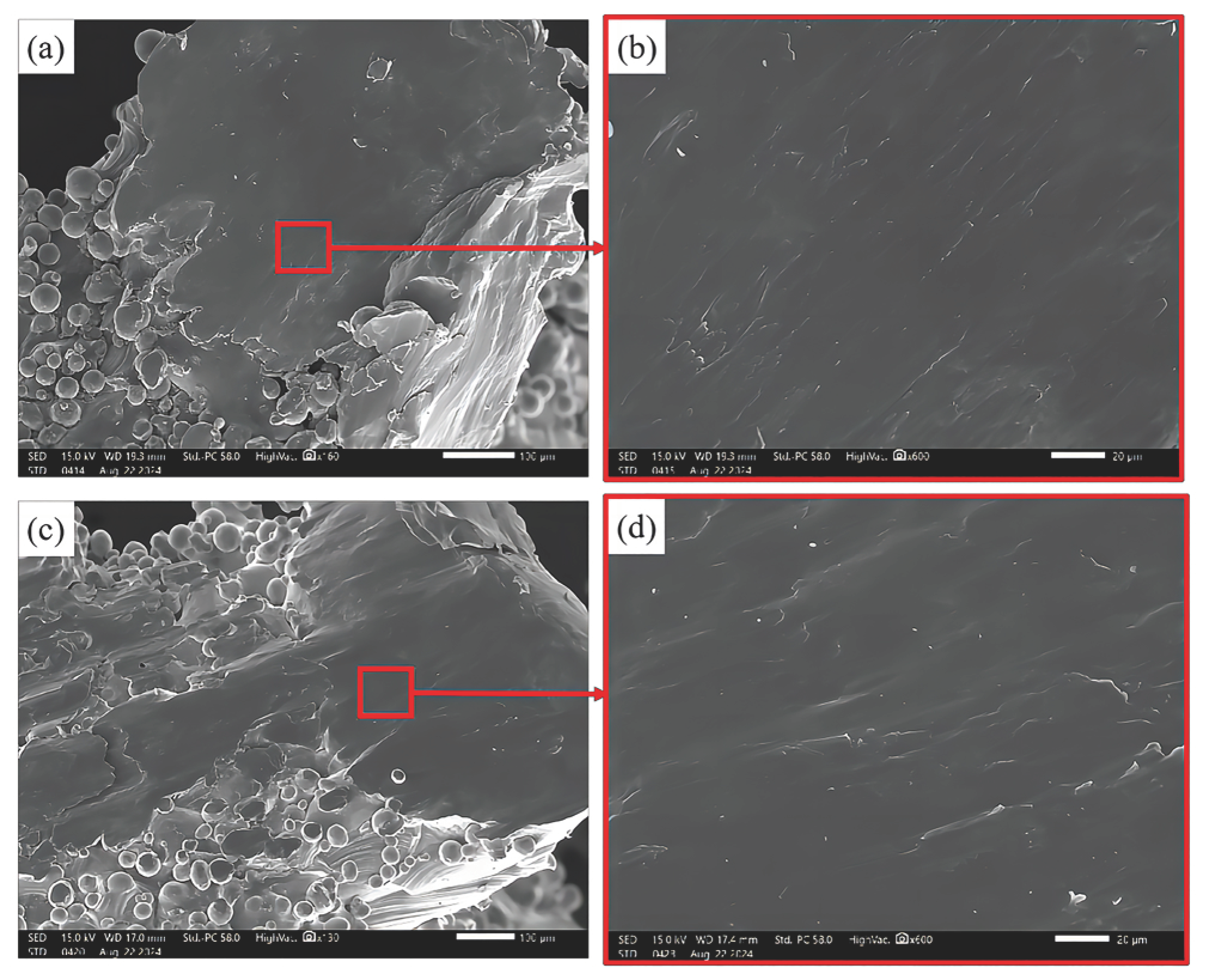
To further investigate the failure mechanism of the Ti6Al4V alloy lattice structure, scanning electron microscopy (SEM) was used to observe the fracture surface morphology of the samples after different compression load tests, as shown in Figure 9. It was found that the fracture surface morphology consisted of smooth planar surfaces and a few large-sized tear ridges, both under longitudinal and transverse compressive loading conditions. This indicates that the primary fracture mechanism of the samples is brittle fracture, with a localized post-yield response occurring before damage. Therefore, the compression fracture mechanism of the Ti6Al4V lattice structure fabricated by LPBF is a quasi-cleavage fracture, which is also consistent with the results of Sun et al. [46] and Zhang et al. [47].
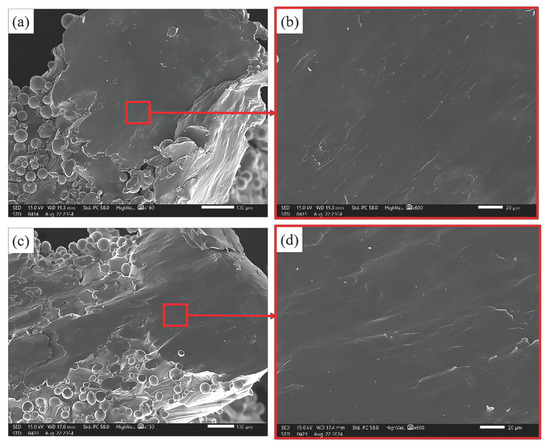
Figure 9.
SEM images of compression fracture surface morphology of Ti6Al4V lattice structure: (a) overall fracture morphology of longitudinal compression; (b) enlarged image of the red-marked area in (a); (c) overall fracture morphology of transverse compression; (d) enlarged image of the red-marked area in (c).
3.3. Compression Deformation Characteristics
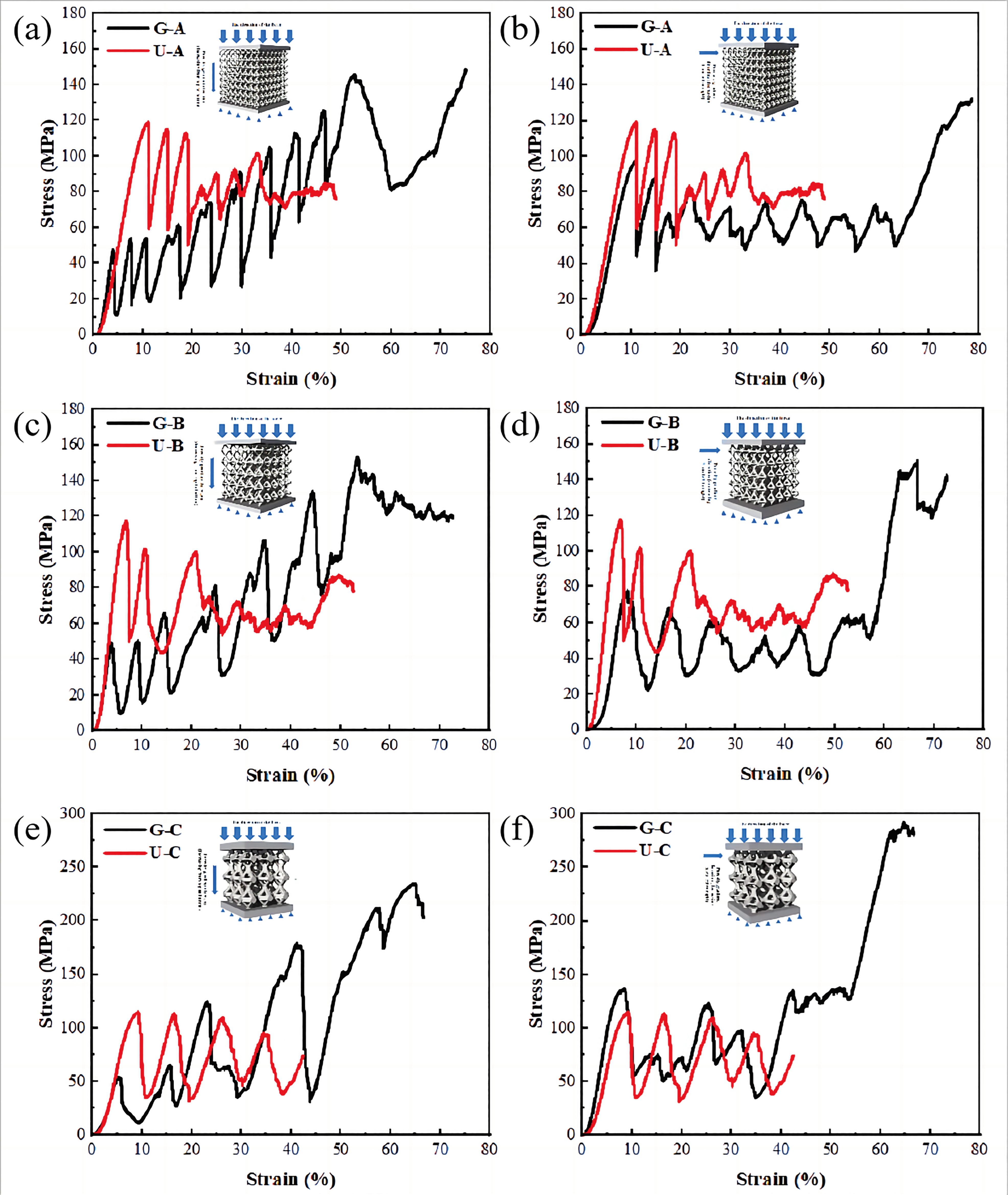
Figure 10 demonstrates the relationship between stress and strain in compression along different loading directions for gradient lattice and uniform lattice structures with equal average porosity. It can be found that, at the initial stage of loading, both gradient lattice and uniform lattice structures under the two loading conditions show obvious elastic behaviors. As the deformation increases, they gradually enter the plastic plateau and densification stages. The samples exhibit significant post-yield strain hardening under longitudinal compressive loading as shown by the curves in Figure 10a–c. Although a significant post-yield stress drop occurs for all three structures, as compression proceeds, the stress values again reach the initial peak stress and gradually rise above the peak stress. When the average porosity is constant, the average compressive strength of the LPBF gradient lattice structure increases with the increase in the porosity gradient. As the porosity gradient increases from 1.05% (Figure 10a) to 3.69% (Figure 10c), the average compressive strength rises from 108.78 MPa to 166.82 MPa, which is 16.40%, 20.63%, and 50.87% higher than that of the corresponding uniform lattice structures, respectively. These experimental results are also consistent with those of Choy et al. [48] and Cardeña et al. [49]. The average compressive strength of the same structure is about 12%–15% higher than that of Sancho’s BCC lattice structure. This phenomenon can be attributed to the result of the increase in diameter of the single-cell pillars and the increase in the porosity gradient, leading to an increase in the yield strength of the LPBF gradient lattice structure.
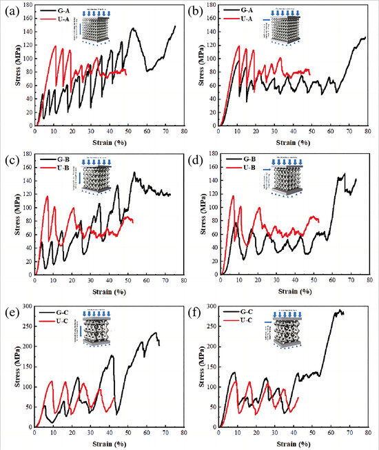
Figure 10.
Compressive stress–strain curves of different gradient lattice and uniform lattice structures with equal average porosity: (a–c) longitudinal loading; (d–f) compression under transverse loading.
As shown in the curves of Figure 10d–f, the deformation of the samples under transverse compressive loading exhibits a strain-softening behavior similar to that of a uniform lattice structure. After the stress reaches the first peak value, the stress remains below the peak stress before the sample undergoes densification. This is because the overall structure of the sample has been locally destroyed (Figure 8). The compressive strength is significantly reduced, which leads to a lower loading capacity of the sample after plastic failure. It was observed that during the plastic plateau stage, the stress value of G-A showed the largest change compared to the maximum compressive strength, decreasing by approximately 21.43%. It exhibited low-amplitude stress variations, demonstrating a more uniform plastic plateau region. The large increase in the stress values of the samples with increasing deformation is due to the gradual densification of the samples as compression proceeds.
3.4. Cumulative Energy Absorption and Energy Absorption Efficiency Under Compressive Deformation Behavior
Cumulative energy absorption (W) is usually an important measure of the ductility of lattice structures and can be used to determine the total amount of energy absorbed by the material or system under external pressure. The calculation formula is given in Equation (2) [50]. Maximum stress is an important factor in energy absorption applications. The energy absorption efficiency (η) is used to evaluate the energy absorption characteristics of lattice structures and is defined as the energy absorbed at any strain divided by the peak stress. The calculation formula is given in Equation (3) [51].
In the equation, σ and ε are the stress and strain during the compression test. W is the cumulative energy absorption value (MJ/mm3), which can be calculated from the compressive stress–strain curve. σ(ε) is the corresponding peak stress at a certain ε, and η(ε) is the energy absorption efficiency.
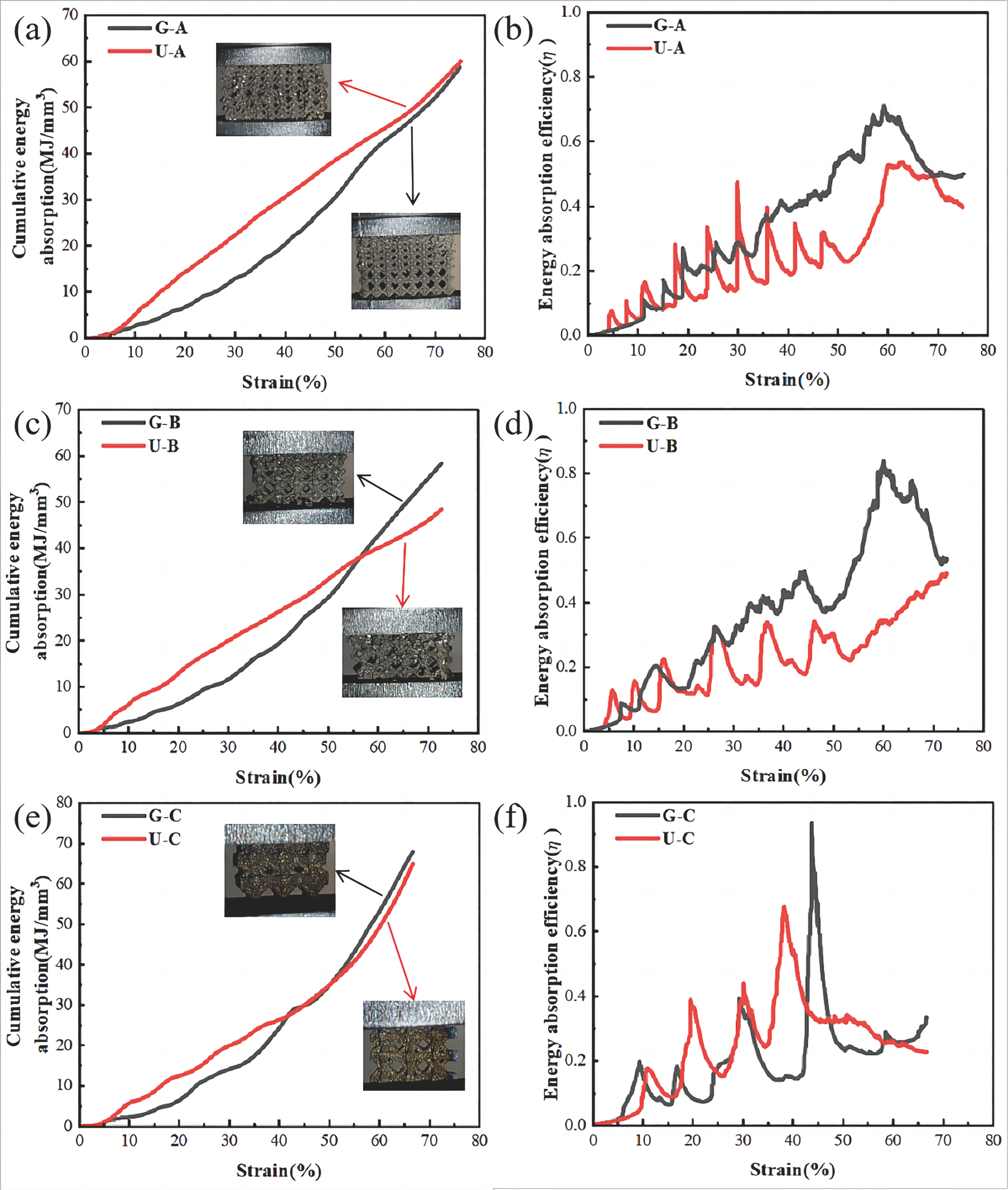
The relationships between cumulative energy absorption and energy absorption efficiency and strain were experimentally investigated for gradient lattice and uniform lattice structures with equal porosity under longitudinal loading conditions, as shown in Figure 11. The results show that the cumulative energy absorption of both the gradient lattice structure and the uniform lattice structure increased with the increase in deformation, almost linearly (see Figure 11a–c). In the elastic deformation stage, the cumulative energy absorption of the uniform lattice structure is higher than that of the gradient lattice structure. As the deformation increases, the energy absorption of the gradient lattice structure gradually increases. The cumulative energy absorption of the gradient lattice structure appears to be higher than that of the uniform lattice structure in the plateau region. This is because, with the increase in deformation, the energy absorption efficiency of the gradient lattice structure gradually surpasses that of the uniform lattice structure (e.g., Figure 11d–f). Meanwhile, with the increase in the porosity gradient, the gradient lattice structure can absorb more energy with a smaller deformation. The cumulative energy absorption of G-B and G-C increased by 20.43% and 7.69%, respectively, compared to that of the uniform lattice structure. The energy absorption efficiency was approximately 32% and 47% higher than that of the corresponding uniform lattice structures. The reason that the cumulative energy and energy absorption efficiency of the G-A structure approximates that of the uniform dot matrix structure may be because the layer-by-layer porosity gradient of the G-C structure is only 1%. The overall structure tends to be more like that of the uniform dot matrix structure. It is observed that the gradual decrease in deformation corresponding to the critical point from Figure 11a–c is due to the increase in porosity gradient. In the subsequent deformation process, the energy absorption of the gradient lattice structure is greater than that of the uniform lattice structure and continues to increase. The characteristics of the energy absorption efficiency and strain relationship curves in Figure 11d–f also confirm this result effectively.
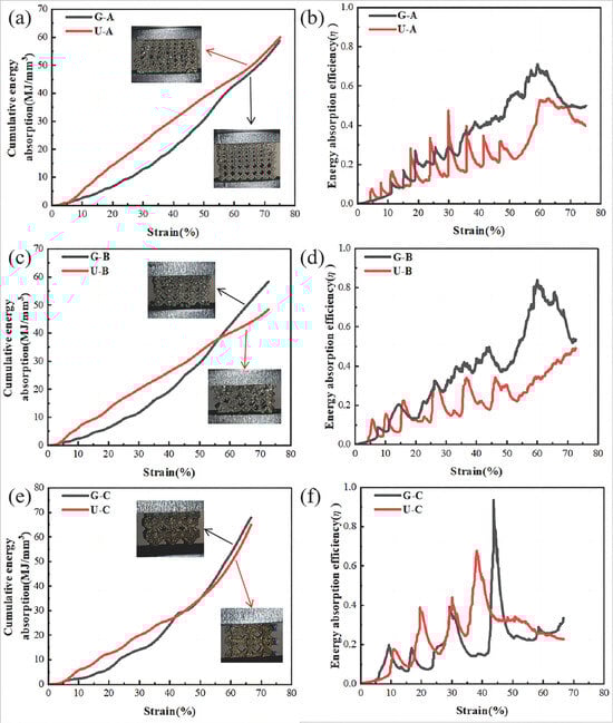
Figure 11.
Uniform lattice structure and gradient lattice structure: (a–c) cumulative energy absorption–strain curve; (d–f) cumulative absorption efficiency–strain curve.
It is crucial to compare the average compressive strength and cumulative energy absorption of this study with the results from the existing literature. However, research on gradient lattice structures with energy absorption characteristics manufactured by LPBF is very limited. Choy et al. [48] reported that, for gradient lattice structures of the same material and type, the average compressive strength reached 113 MPa, and the cumulative energy absorption was 95 MJ/mm3. In comparison, the corresponding uniform lattice structure had an even higher average compressive strength of 172 MPa. Compared to our study, the higher average compressive strength and cumulative energy absorption in their research can be attributed to the fact that their lattice structure had a porosity of only 71%, which is about 14% lower than the porosity of the lattice structure in our experiment. As a result, their overall structure was heavier, allowing them to bear larger loads. Although it is not entirely fair to directly compare the experimental results due to the differences in porosity and porosity gradient, the impact of varying porosity and porosity gradients on compressive strength and cumulative energy absorption is worth further discussion.
4. Conclusions
In this work, uniform and gradient lattice structures with the same porosity based on topology-optimized design were fabricated by an LPBF process, and their compression behavior was investigated. The conclusions are as follows:
- (1)
- With the same microstructure and average porosity, the gradient lattice exhibits better compression performance, with a cumulative energy absorption capacity significantly superior to that of the uniform lattice structure.
- (2)
- This superior performance is attributed to the fact that, under compressive loading, the gradient lattice exhibits layer-by-layer shear failure, whereas the uniform lattice experiences overall random failure.
- (3)
- The gradient structure exhibits a greater total deformation before failure than the uniform lattice structure. However, as the deformation increases, the energy absorption efficiency slightly decreases after the deformation exceeds 50%. This indicates that the densification of the structure reduces its energy absorption efficiency.
Author Contributions
Conceptualization, H.W.; Methodology, Z.G. and Y.M.; Software, Z.G. and Y.M.; Validation, T.A., Y.Y., J.H., S.L. and H.W.; Formal analysis, Z.G. and Y.M.; Investigation, Z.G., Y.M. and T.A.; Resources, Y.Y., J.H., S.L. and H.W.; Writing—original draft, Z.G. and Y.M.; Writing—review and editing, Z.G., T.A., Y.Y., J.H., S.L. and H.W.; Visualization, Z.G. and Y.M.; Supervision, Y.Y., J.H., S.L. and H.W.; Project administration, H.W.; Funding acquisition, H.W. All authors have read and agreed to the published version of the manuscript.
Funding
This work is financially supported by the National Natural Science Foundation of China (U2241245 and 52321001), the Aeronautical Science Foundation of China (2022Z053092001), the Natural Science Foundation of Shenyang (23-503-6-05), the Shanghai Science and Technology Development Funds (22QB1406500), and the Liaoning Provincial Science and Technology Major Project (2024JH1/11700028).
Data Availability Statement
The original contributions presented in the study are included in the article, further inquiries can be directed to the corresponding authors.
Conflicts of Interest
The authors declare no conflict of interest.
References
- Hao, Y.-L.; Li, S.-J.; Yang, R. Biomedical titanium alloys and their additive manufacturing. Rare Met. 2016, 35, 661–671. [Google Scholar] [CrossRef]
- Qian, M.; Bourell, D.L. Additive Manufacturing of Titanium Alloys. JOM 2017, 69, 2677–2678. [Google Scholar] [CrossRef]
- Wang, M.; Lin, X.; Huang, W. Laser additive manufacture of titanium alloys. Mater. Technol. 2016, 31, 90–97. [Google Scholar] [CrossRef]
- Zhang, J.; Liu, Y.; Babamiri, B.B.; Zhou, Y.; Dargusch, M.; Hazeli, K.; Zhang, M.-X. Enhancing specific energy absorption of additively manufactured titanium lattice structures through simultaneous manipulation of architecture and constituent material. Addit. Manuf. 2022, 55, 102887. [Google Scholar] [CrossRef]
- Sun, G.; Chen, D.; Zhu, G.; Li, Q. Lightweight hybrid materials and structures for energy absorption: A state-of-the-art review and outlook. Thin-Walled Struct. 2022, 172, 108760. [Google Scholar] [CrossRef]
- Pan, X.; Qian, G.; Wu, S.; Fu, Y.; Hong, Y. Internal crack characteristics in very-high-cycle fatigue of a gradient structured titanium alloy. Sci. Rep. 2020, 10, 4742. [Google Scholar] [CrossRef] [PubMed]
- Zhan, Z.; Li, H.; Lam, K. Development of a novel fatigue damage model with AM effects for life prediction of commonly-used alloys in aerospace. Int. J. Mech. Sci. 2019, 155, 110–124. [Google Scholar] [CrossRef]
- He, S.; Zhu, J.; Jing, Y.; Long, S.; Tang, L.; Cheng, L.; Shi, Z. Effect of 3D-Printed Porous Titanium Alloy Pore Structure on Bone Regeneration: A Review. Coatings 2024, 14, 253. [Google Scholar] [CrossRef]
- Song, C.; Liu, L.; Deng, Z.; Lei, H.; Yuan, F.; Yang, Y.; Li, Y.; Yu, J. Research progress on the design and performance of porous titanium alloy bone implants. J. Mater. Res. Technol. 2023, 23, 2626–2641. [Google Scholar] [CrossRef]
- Bian, X.; Yuan, F.; Zhu, Y.; Wu, X. Gradient structure produces superior dynamic shear properties. Mater. Res. Lett. 2017, 5, 501–507. [Google Scholar] [CrossRef]
- Xiao, Z.; Yang, Y.; Xiao, R.; Bai, Y.; Song, C.; Wang, D. Evaluation of topology-optimized lattice structures manufactured via selective laser melting. Mater. Des. 2018, 143, 27–37. [Google Scholar] [CrossRef]
- Chen, L.; Che, J.; Liang, S.; Wang, Y. Multiscale topology optimization of gradient lattice structure based on volume parametric modeling. Compos. Struct. 2023, 328, 117746. [Google Scholar] [CrossRef]
- Li, J.; Huang, Z.; Liu, G.; An, Q.; Chen, M. Topology optimization design and research of lightweight biomimetic three-dimensional lattice structures based on laser powder bed fusion. J. Manuf. Process. 2021, 74, 220–232. [Google Scholar] [CrossRef]
- Li, T.; Sun, B.; Gan, N. Lattice infill structure design of topology optimization considering size effect. Math. Mech. Solids 2022, 28, 873–890. [Google Scholar] [CrossRef]
- Belda, R.; Megías, R.; Marco, M.; Vercher-Martínez, A.; Giner, E. Numerical analysis of the influence of triply periodic minimal surface structures morphometry on the mechanical response. Comput. Methods Programs Biomed. 2023, 230, 107342. [Google Scholar] [CrossRef] [PubMed]
- Zhao, M.; Liu, F.; Fu, G.; Zhang, D.Z.; Zhang, T.; Zhou, H. Improved Mechanical Properties and Energy Absorption of BCC Lattice Structures with Triply Periodic Minimal Surfaces Fabricated by SLM. Materials 2018, 11, 2411. [Google Scholar] [CrossRef] [PubMed]
- Bai, L.; Zhang, J.; Chen, X.; Yi, C.; Chen, R.; Zhang, Z. Configuration Optimization Design of Ti6Al4V Lattice Structure Formed by SLM. Materials 2018, 11, 1856. [Google Scholar] [CrossRef]
- Bahnini, I.; Rivette, M.; Rechia, A.; Siadat, A.; Elmesbahi, A. Additive manufacturing technology: The status, applications, and prospects. Int. J. Adv. Manuf. Technol. 2018, 97, 147–161. [Google Scholar] [CrossRef]
- Trevisan, F.; Calignano, F.; Lorusso, M.; Pakkanen, J.; Aversa, A.; Ambrosio, E.P.; Lombardi, M.; Fino, P.; Manfredi, D. On the Selective Laser Melting (SLM) of the AlSi10Mg Alloy: Process, Microstructure, and Mechanical Properties. Materials 2017, 10, 76. [Google Scholar] [CrossRef] [PubMed]
- Razavykia, A.; Brusa, E.; Delprete, C.; Yavari, R. An Overview of Additive Manufacturing Technologies—A Review to Technical Synthesis in Numerical Study of Selective Laser Melting. Materials 2020, 13, 3895. [Google Scholar] [CrossRef] [PubMed]
- Oropeza, D.; Seager, T.; Firdosy, S.; Guerra, J.; Billings, K.; Jones, J.-P.; Hofmann, D.C.; Roberts, S. Porosity control of copper-based alloys via powder bed fusion additive manufacturing for spacecraft applications. J. Porous Mater. 2024, 31, 779–791. [Google Scholar] [CrossRef]
- Yao, L.; Ramesh, A.; Xiao, Z.; Chen, Y.; Zhuang, Q. Multimetal Research in Powder Bed Fusion: A Review. Materials 2023, 16, 4287. [Google Scholar] [CrossRef] [PubMed]
- Hayat, M.D.; Singh, H.; He, Z.; Cao, P. Titanium metal matrix composites: An overview. Compos. Part A Appl. Sci. Manuf. 2019, 121, 418–438. [Google Scholar] [CrossRef]
- Gao, B.; Zhao, H.; Peng, L.; Sun, Z. A Review of Research Progress in Selective Laser Melting (SLM). Micromachines 2022, 14, 57. [Google Scholar] [CrossRef] [PubMed]
- Liu, Y.; Ren, D.; Li, S.; Wang, H.; Zhang, L.; Sercombe, T. Enhanced fatigue characteristics of a topology-optimized porous titanium structure produced by selective laser melting. Addit. Manuf. 2020, 32, 101060. [Google Scholar] [CrossRef]
- Chen, J.; Fan, M.; Zhou, L.; Chen, W.; Ren, Y.; Li, W.; Huang, W.; Niu, Y.; Li, Z.; Li, C. The effect of microstructure on the fatigue behavior of titanium alloy graded porous structures fabricated by selective laser melting. J. Mater. Res. Technol. 2023, 27, 4290–4304. [Google Scholar] [CrossRef]
- Hu, Y.; Chen, H.; Liang, X.; Jia, M.; Lei, J. Microstructure and Biomechanical Properties in Selective Laser Melting of Porous Metal Implants. 3D Print. Addit. Manuf. 2021, 10, 1003–1014. [Google Scholar] [CrossRef] [PubMed]
- Ren, Y.; Ran, W.; Nie, Y.; Liu, Z.; Lou, C.; Li, J.; Chen, W. Excellent Mechanical Properties and Energy Absorption of Hexagonal-Body-Centered Lattice Structure Fabricated by Selective Laser Melting. Adv. Eng. Mater. 2023, 25, 2300431. [Google Scholar] [CrossRef]
- Li, H.; Yang, G.; Lv, S.; Zhou, Q.; Fan, L.; Liu, R.; Yao, J.; Tong, P. Effects of Unit Cell Topology on the Mechanical Properties of Porous Tantalum Structures via Laser Powder Bed Fusion. Adv. Eng. Mater. 2022, 25, 2201431. [Google Scholar] [CrossRef]
- Wang, Z.; Jiang, X.; Yang, G.; Song, B.; Sha, H. Design and mechanical performance analysis of T-BCC lattice structures. J. Mater. Res. Technol. 2024, 32, 1538–1551. [Google Scholar] [CrossRef]
- Pauly, S.; Schricker, C.; Scudino, S.; Deng, L.; Kühn, U. Processing a glass-forming Zr-based alloy by selective laser melting. Mater. Des. 2017, 135, 133–141. [Google Scholar] [CrossRef]
- Li, X.; Roberts, M.; O’Keeffe, S.; Sercombe, T. Selective laser melting of Zr-based bulk metallic glasses: Processing, microstructure and mechanical properties. Mater. Des. 2016, 112, 217–226. [Google Scholar] [CrossRef]
- Chen, Z.; Wu, X.; Davies, C.H. Process variation in Laser Powder Bed Fusion of Ti-6Al-4V. Addit. Manuf. 2021, 41, 101987. [Google Scholar] [CrossRef]
- Chen, Z.; Wu, X.; Tomus, D.; Davies, C.H. Surface roughness of Selective Laser Melted Ti-6Al-4V alloy components. Addit. Manuf. 2018, 21, 91–103. [Google Scholar] [CrossRef]
- Liu, J.; Zhang, K.; Liu, J.; Wang, H.; Yang, Y.; Yan, L.; Tian, X.; Zhu, Y.; Huang, A. Investigation of fatigue behavior of laser powder bed fusion Ti-6Al-4V: Roles of heat treatment and microstructure. Int. J. Fatigue 2023, 176, 107839. [Google Scholar] [CrossRef]
- Liu, J.; Zhang, K.; Liu, J.; Xu, Y.; Zhang, R.; Zeng, Z.; Zhu, Y.; Huang, A. In-situ investigation into the deformation behavior of Ti-6Al-4V processed by laser powder bed fusion. Mater. Charact. 2022, 194, 112434. [Google Scholar] [CrossRef]
- Aslan, B.; Yıldız, A.R. Optimum design of automobile components using lattice structures for additive manufacturing. Mater. Test. 2020, 62, 633–639. [Google Scholar] [CrossRef]
- ISO 13314-2011; Mechanical Testing of Metals—Ductility Testing—Compression Test for Porous and Cellular Metals. ISO: Geneva, Switzerland, 2011.
- Sugaya, K.; Imamura, T. Turbulent flow simulations of the common research model on Cartesian grids using recursive fitting approach. J. Comput. Phys. 2022, 467, 111460. [Google Scholar] [CrossRef]
- Hu, C.; Liu, C. Development of Cartesian grid method for simulation of violent ship-wave interactions. J. Hydrodyn. 2016, 28, 1003–1010. [Google Scholar] [CrossRef]
- Marker, C.; Shang, S.-L.; Zhao, J.-C.; Liu, Z.-K. Effects of alloying elements on the elastic properties of bcc Ti-X alloys from first-principles calculations. Comput. Mater. Sci. 2018, 142, 215–226. [Google Scholar] [CrossRef]
- Ren, Y.; Ma, Y.; Pan, Q. Effect of Microstructure on the Johnson-Cook Constitutive Model Parameters of Ti-6Al-4V Alloy. J. Phys. Conf. Ser. 2020, 1637, 012018. [Google Scholar] [CrossRef]
- Löschner, P.; Gupta, M.K.; Niesłony, P.; Korkmaz, M.E.; Jamil, M. Determination and Verification of the Johnson–Cook Constitutive Model Parameters in the Precision Machining of Ti6Al4V Alloy. Machines 2024, 12, 709. [Google Scholar] [CrossRef]
- Polley, C.; Radlof, W.; Hauschulz, F.; Benz, C.; Sander, M.; Seitz, H. Morphological and mechanical characterisation of three-dimensional gyroid structures fabricated by electron beam melting for the use as a porous biomaterial. J. Mech. Behav. Biomed. Mater. 2022, 125, 104882. [Google Scholar] [CrossRef] [PubMed]
- Li, X.; Xiao, L.; Song, W. Compressive behavior of selective laser melting printed Gyroid structures under dynamic loading. Addit. Manuf. 2021, 46, 102054. [Google Scholar] [CrossRef]
- Sun, Q.; Sun, J.; Guo, K.; Wang, L. Compressive mechanical properties and energy absorption characteristics of SLM fabricated Ti6Al4V triply periodic minimal surface cellular structures. Mech. Mater. 2022, 166, 104241. [Google Scholar] [CrossRef]
- Zhang, M.; Yang, Y.; Wang, D.; Xiao, Z.; Song, C.; Weng, C. Effect of heat treatment on the microstructure and mechanical properties of Ti6Al4V gradient structures manufactured by selective laser melting. Mater. Sci. Eng. A 2018, 736, 288–297. [Google Scholar] [CrossRef]
- Choy, S.Y.; Sun, C.-N.; Leong, K.F.; Wei, J. Compressive properties of functionally graded lattice structures manufactured by selective laser melting. Mater. Des. 2017, 131, 112–120. [Google Scholar] [CrossRef]
- Cardeña, A.; Sancho, R.; Barba, D.; Gálvez, F. Dynamic behaviour of additively manufactured Ti6Al4V BCC lattice-based structures. Mater. Lett. 2023, 354, 135286. [Google Scholar] [CrossRef]
- Tan, Q.; Liu, P.; Du, C.; Wu, L.; He, G. Mechanical behaviors of quasi-ordered entangled aluminum alloy wire material. Mater. Sci. Eng. A 2009, 527, 38–44. [Google Scholar] [CrossRef]
- Wu, F.; Zhou, Z.; Yao, B.; Xiao, Z. Anisotropic Compressive Properties and Energy Absorption Efficiency of Porous Twisted Short Fiber Materials. Steel Res. Int. 2016, 87, 1534–1542. [Google Scholar] [CrossRef]

Disclaimer/Publisher’s Note: The statements, opinions and data contained in all publications are solely those of the individual author(s) and contributor(s) and not of MDPI and/or the editor(s). MDPI and/or the editor(s) disclaim responsibility for any injury to people or property resulting from any ideas, methods, instructions or products referred to in the content. |
© 2025 by the authors. Licensee MDPI, Basel, Switzerland. This article is an open access article distributed under the terms and conditions of the Creative Commons Attribution (CC BY) license (https://creativecommons.org/licenses/by/4.0/).