
Interfacial Cracking Failure Mechanism of Chromium-Coated Zircaloy Cladding for ATF Materials


Abstract
1. Introduction
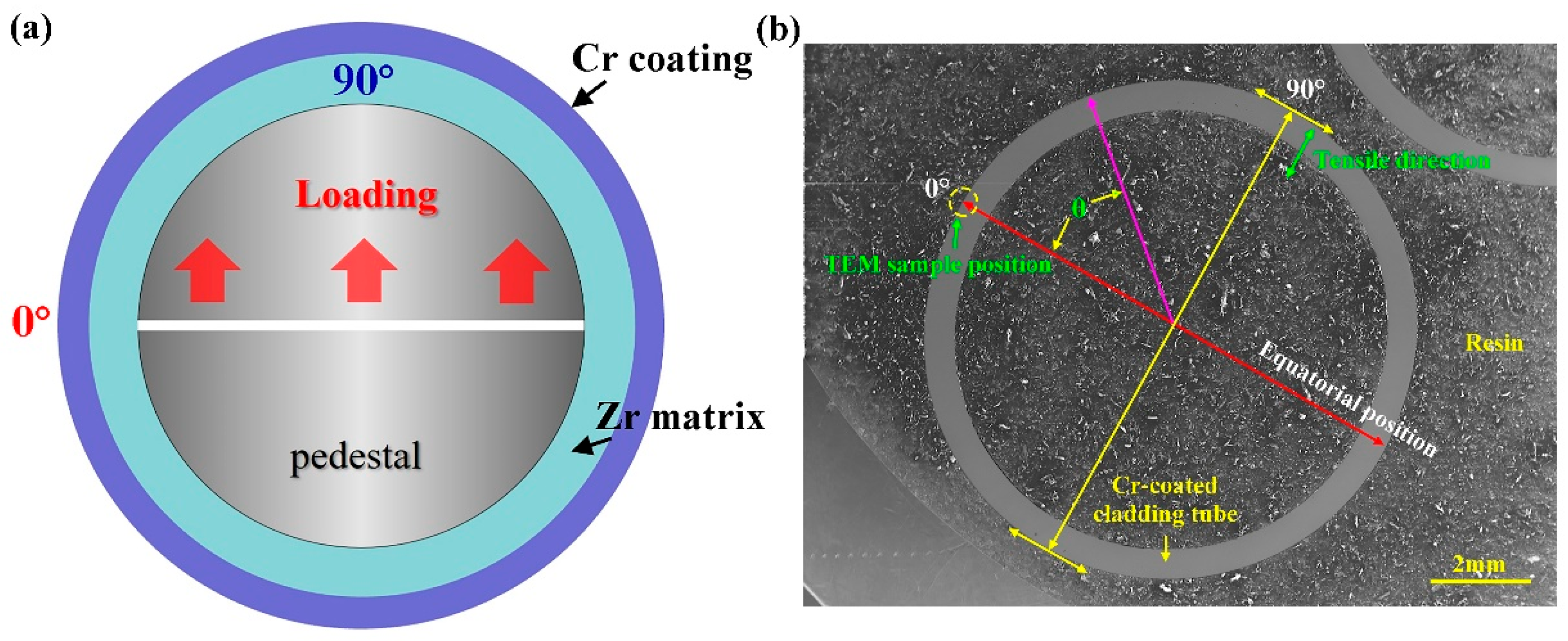
2. Experimental Procedures
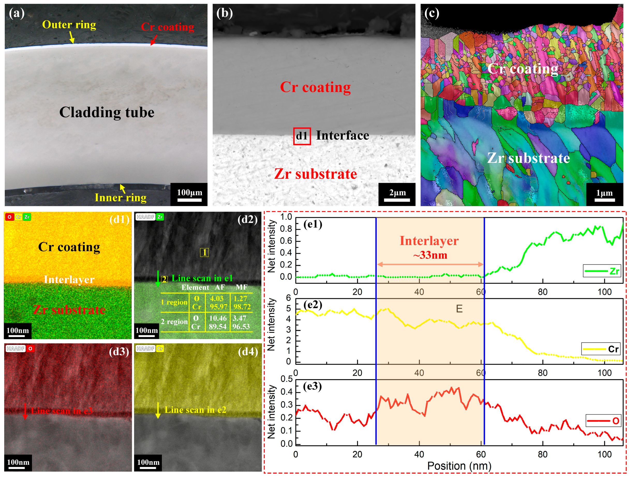
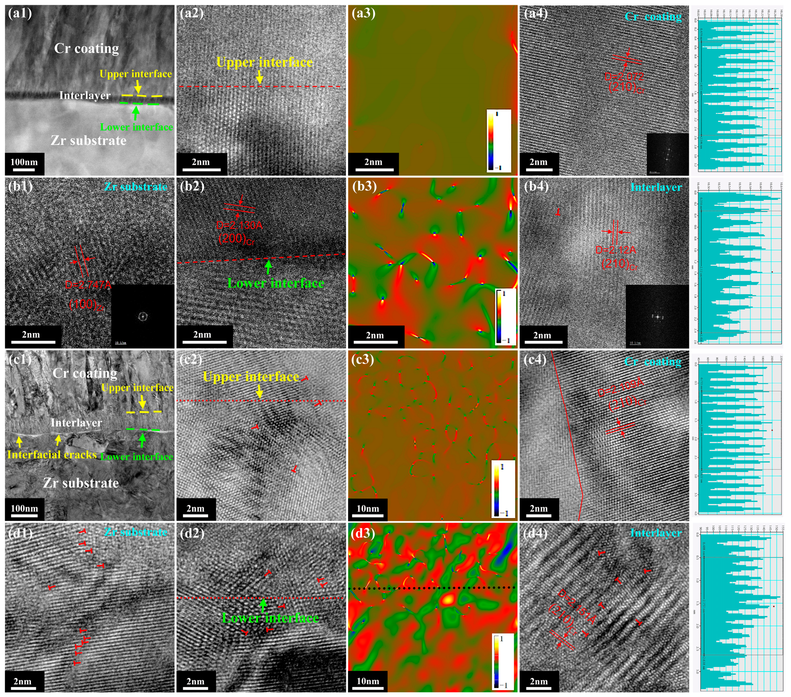
3. Results
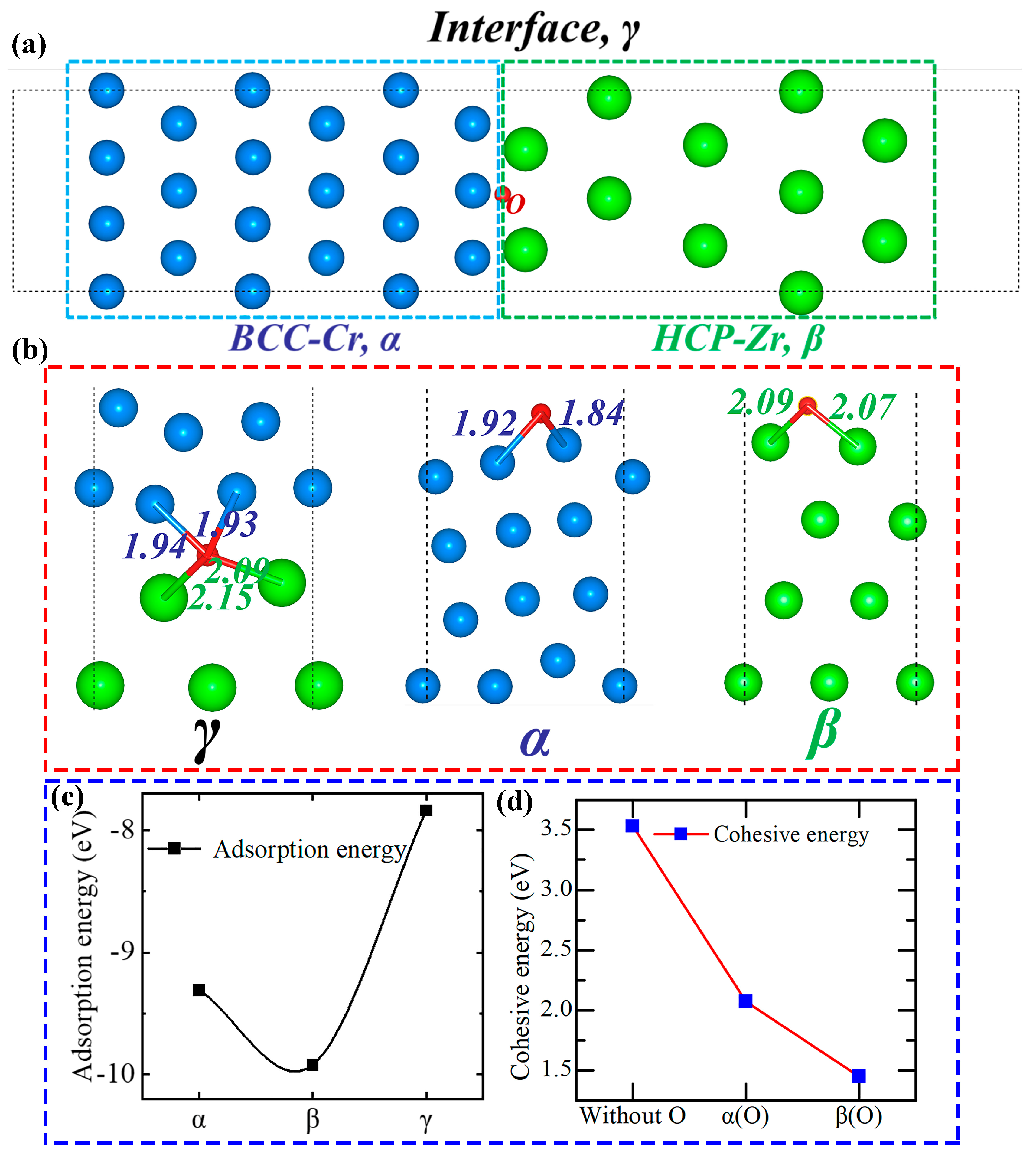
4. Discussion
5. Conclusions
Author Contributions
Funding
Data Availability Statement
Acknowledgments
Conflicts of Interest
References
- Steinbrueck, M.; Grosse, M.; Tang, C.; Stuckert, J.; Seifert, H.J. An Overview of Mechanisms of the Degradation of Promising ATF Cladding Materials During Oxidation at High Temperatures. High Temp. Corros. Mater. 2024, 101, 621–647. [Google Scholar] [CrossRef]
- Kim, J.; Lee, C.Y.; Rho, H.; Kim, D.; Lee, J.; Jang, H.; Lee, Y. Elucidating changes in thermal creep strain rate of Cr-coated Zr-Nb alloy Accident Tolerant Fuel (ATF) cladding via experiment and mechanical analysis. J. Nucl. Mater. 2024, 592, 154947. [Google Scholar] [CrossRef]
- Yang, J.; Steinbrück, M.; Tang, C.; Große, M.; Liu, J.; Zhang, J.; Yun, D.; Wang, S. Review on chromium coated zirconium alloy accident tolerant fuel cladding. J. Alloys Compd. 2022, 895, 162450. [Google Scholar] [CrossRef]
- Li, X.; Zhang, J.; Fu, Q.; Akiyama, E.; Song, X.; Wang, Y.; Li, Q.; Zou, N. Tensile mechanical properties and fracture behaviors of nickel-based superalloy 718 in the presence of hydrogen. Int. J. Hydrogen Energy 2018, 43, 20118–20132. [Google Scholar] [CrossRef]
- Li, X.; Meng, C.; Xu, X.; He, X.; Wang, C. Effect of Al content on high-temperature oxidation behavior and failure mechanism of CrAl-coated Zircaloy. Corros. Sci. 2021, 192, 109856. [Google Scholar] [CrossRef]
- Fazi, A.; Sattari, M.; Stiller, K.; Andrén, H.-O.; Thuvander, M. Performance and evolution of cold spray Cr-coated optimized ZIRLO™ claddings under simulated loss-of-coolant accident conditions. J. Nucl. Mater. 2023, 576, 154268. [Google Scholar] [CrossRef]
- Li, Z.; Wang, Z.; Ma, G.; Chen, R.; Yang, W.; Wang, K.; Ke, P.; Wang, A. High-performance Cr2AlC MAX phase coatings for ATF application: Interface design and oxidation mechanism. Corros. Commun. 2024, 13, 27–36. [Google Scholar] [CrossRef]
- Jung, T.S.; Jang, H.; Cho, Y.K.; Jang, D. Degradation behavior of chromium-coated zirconium cladding under 1200 °C steam oxidation according to the coating microstructure. J. Nucl. Mater. 2025, 603, 155360. [Google Scholar] [CrossRef]
- AlHamadi, F.; An, B.; Yi, Y.; Alameri, S.A.; Choi, D. Evaluation of high-temperature oxidation behaviour of ATF claddings during severe accidents in nuclear power plants. Nucl. Eng. Des. 2024, 426, 113388. [Google Scholar] [CrossRef]
- Wang, Y.; Zuo, J.; Xiao, X.; Wu, K.; Zhang, J.; Liu, G.; Sun, J. High-temperature steam oxidation behavior and failure mechanisms of Al alloyed Cr coatings on Zr-4 alloy. Corros. Sci. 2024, 230, 111898. [Google Scholar] [CrossRef]
- Meng, C.; Ma, J.; Wang, H.; Liu, W.; Hu, Y.; Zhang, B.; Tu, M.; Yuan, C.; He, X. Enhancing the oxidation behaviors of Zr alloys for nuclear fuel cladding using nanolamellar Cr/CrN coating. Corros. Sci. 2023, 227, 111725. [Google Scholar] [CrossRef]
- Li, X.; Liu, Y.; Cui, Y.; Zhang, J.; Fu, J. Mechanical property and cracking mechanism of Cr-coated Zr alloy under tensile and compressive loading. Mater. Today Commun. 2024, 41, 110422. [Google Scholar] [CrossRef]
- Kim, H.-G.; Kim, I.-H.; Jung, Y.-I.; Park, D.-J.; Park, J.-Y.; Koo, Y.-H. Adhesion property and high-temperature oxidation behavior of Cr-coated Zircaloy-4 cladding tube prepared by 3D laser coating. J. Nucl. Mater. 2015, 465, 531–539. [Google Scholar] [CrossRef]
- Joung, S.; Yook, H.; Kim, D.; Lee, Y. Exploring the Peak Cladding Temperature Limit of Cr-coated ATF Cladding by Assessing the Impact of the Zr-Cr Eutectic on the Structural Integrity of Cladding. J. Nucl. Mater. 2025, 605, 155577. [Google Scholar] [CrossRef]
- Yang, Z.; Li, B.; Xu, J.; Zhong, Y.; Xie, L.; Chu, M.; Wang, Y.; Gao, R.; Yu, L.; Wang, M.; et al. A novel class of ATF fuels with large grain size, enhanced thermophysical properties and oxidation resistance. Ceram. Int. 2024, 50, 18986–18992. [Google Scholar] [CrossRef]
- Jiao, Y.-J.; Li, Z.-Y.; Pu, Z.-P.; Zheng, M.-Y.; Ren, Q.-Y.; Cai, Z.-B.; Wu, Y.-W.; Qiu, S.-Z. Study on the fretting wear performance of oxide layer and Cr coating on zirconium alloy in high-temperature water. Wear 2024, 560, 205597. [Google Scholar] [CrossRef]
- Ribis, J.; Wu, A.; Brachet, J.-C.; Barcelo, F.; Arnal, B. Atomic-scale interface structure of a Cr-coated Zircaloy-4 material. J. Mater. Sci. 2018, 53, 9879–9895. [Google Scholar] [CrossRef]
- Yeom, H.; Maier, B.; Johnson, G.; Dabney, T.; Lenling, M.; Sridharan, K. High temperature oxidation and microstructural evolution of cold spray chromium coatings on Zircaloy-4 in steam environments. J. Nucl. Mater. 2019, 526, 151737. [Google Scholar] [CrossRef]
- Brachet, J.-C.; Rouesne, E.; Ribis, J.; Guilbert, T.; Urvoy, S.; Nony, G.; Toffolon-Masclet, C.; Le Saux, M.; Chaabane, N.; Palancher, H.; et al. High temperature steam oxidation of chromium-coated zirconium-based alloys: Kinetics and process. Corros. Sci. 2020, 167, 108537. [Google Scholar] [CrossRef]
- Han, X.; Xue, J.; Peng, S.; Zhang, H. An interesting oxidation phenomenon of Cr coatings on Zry-4 substrates in high temperature steam environment. Corros. Sci. 2019, 156, 117–124. [Google Scholar] [CrossRef]
- Yang, J.; Stegmaier, U.; Tang, C.; Steinbrück, M.; Große, M.; Wang, S.; Seifert, H.J. High temperature Cr-Zr interaction of two types of Cr-coated Zr alloys in inert gas environment. J. Nucl. Mater. 2021, 547, 152806. [Google Scholar] [CrossRef]
- Gong, W.; Zhang, H.; Wu, C.; Tian, H.; Wang, X. The role of alloying elements in the initiation of nanoscale porosity in oxide films formed on zirconium alloys. Corros. Sci. 2013, 77, 391–396. [Google Scholar] [CrossRef]
- Jiang, J.; Ma, X.; Wang, B. Positive or negative role of preoxidation in the crack arresting of Cr coating for accident tolerant fuel cladding. Corros. Sci. 2021, 193, 109870. [Google Scholar] [CrossRef]
- Maier, B.; Yeom, H.; Johnson, G.; Dabney, T.; Walters, J.; Romero, J.; Shah, H.; Xu, P.; Sridharan, K. Development of cold spray coatings for accident-tolerant fuel cladding in light water reactors. JOM 2017, 70, 198–202. [Google Scholar] [CrossRef]
- Jiang, J.; Zhai, H.; Gong, P.; Zhang, W.; He, X.; Ma, X.; Wang, B. In-situ study on the tensile behavior of Cr-coated zircaloy for accident tolerant fuel claddings. Surf. Coat. Technol. 2020, 394, 125747. [Google Scholar] [CrossRef]
- Kresse, G.; Furthmüller, J. Efficient iterative schemes for ab initio total-energy calculations using a plane-wave basis set. Phys. Rev. B 1996, 54, 11169. [Google Scholar] [CrossRef]
- Blöchl, P.E. Projector augmented-wave method. Phys. Rev. B 1994, 50, 17953–17979. [Google Scholar] [CrossRef] [PubMed]
- Perdew, J.P.; Chevary, J.A.; Vosko, S.H.; Jackson, K.A.; Pederson, M.R.; Singh, D.J.; Fiolhais, C. Atoms, molecules, solids, and surfaces: Applications of the generalized gradient approximation for exchange and correlation. Phys. Rev. B 1992, 46, 6671–6687, Erratum in Phys. Rev. B 1993, 48, 4978. [Google Scholar] [CrossRef] [PubMed]
- Hui, J.; Zhang, X.; Chen, J.; Liu, M.; Li, X.; Li, R.; Wang, B. AlMgZnCu hydrogen embrittlement by nanograin boundary decomposition. Int. J. Hydrogen Energy 2024, 61, 1142–1156. [Google Scholar] [CrossRef]
- Hui, J.; Zhang, X.; Liu, T.; Liu, W.; Wang, B. First-principles calculation of twin boundary energy and strength/embrittlement in hexagonal close-packed titanium. Mater. Des. 2022, 213, 110331. [Google Scholar] [CrossRef]
- Li, X.; Zhang, J.; Cui, Y.; Djukic, M.B.; Feng, H.; Wang, Y. Review of the hydrogen embrittlement and interactions between hydrogen and microstructural interfaces in metallic alloys: Grain boundary, twin boundary, and nano-precipitate. Int. J. Hydrogen Energy 2024, 72, 74–109. [Google Scholar] [CrossRef]
- Yan, X.; Jiang, Y.; Jin, Q.; Yao, T.; Wang, W.; Tao, A.; Gao, C.; Li, X.; Chen, C.; Ye, H.; et al. Interfacial interaction and intense interfacial ultraviolet light emission at an incoherent interface. Nat. Commun. 2023, 14, 2788. [Google Scholar] [CrossRef] [PubMed]
- Cooper, D.; Le Royer, C.; Béché, A.; Rouvière, J.-L. Strain mapping for the silicon-on-insulator generation of semiconductor devices by high-angle annular dark field scanning electron transmission microscopy. Appl. Phys. Lett. 2012, 100, 233121. [Google Scholar] [CrossRef]
- Verma, N.; Cadambi, S.; Jayaram, V.; Biswas, S.K. Micromechanisms of damage nucleation during contact deformation of columnar multilayer nitride coatings. Acta Mater. 2012, 60, 3063–3073. [Google Scholar] [CrossRef]

Disclaimer/Publisher’s Note: The statements, opinions and data contained in all publications are solely those of the individual author(s) and contributor(s) and not of MDPI and/or the editor(s). MDPI and/or the editor(s) disclaim responsibility for any injury to people or property resulting from any ideas, methods, instructions or products referred to in the content. |
© 2025 by the authors. Licensee MDPI, Basel, Switzerland. This article is an open access article distributed under the terms and conditions of the Creative Commons Attribution (CC BY) license (https://creativecommons.org/licenses/by/4.0/).
Share and Cite
Li, X.; Liu, Y.; Cui, Y.; Hui, J.; Fu, J.; Zhang, J. Interfacial Cracking Failure Mechanism of Chromium-Coated Zircaloy Cladding for ATF Materials. Metals 2025, 15, 179. https://doi.org/10.3390/met15020179
Li X, Liu Y, Cui Y, Hui J, Fu J, Zhang J. Interfacial Cracking Failure Mechanism of Chromium-Coated Zircaloy Cladding for ATF Materials. Metals. 2025; 15(2):179. https://doi.org/10.3390/met15020179
Chicago/Turabian StyleLi, Xinfeng, Yang Liu, Yan Cui, Jun Hui, Jianxun Fu, and Jin Zhang. 2025. "Interfacial Cracking Failure Mechanism of Chromium-Coated Zircaloy Cladding for ATF Materials" Metals 15, no. 2: 179. https://doi.org/10.3390/met15020179
APA StyleLi, X., Liu, Y., Cui, Y., Hui, J., Fu, J., & Zhang, J. (2025). Interfacial Cracking Failure Mechanism of Chromium-Coated Zircaloy Cladding for ATF Materials. Metals, 15(2), 179. https://doi.org/10.3390/met15020179