Article

Study on the Influence Mechanism of Surface Morphology on Wear and Thermal Fatigue Performance of Laser-Treated Bionic Brake Drum

1
School of Mechanical and Electrical Engineering, Jiaxing Nanhu University, Jiaxing 314001, China
2
Jiaxing Key Laboratory of Intelligent Manufacturing and Operation & Maintenance of Automotive Parts, Jiaxing 314001, China
3
College of Intelligent Manufacturing, Suzhou Chien-Shiung Institute of Technology, Suzhou 215411, China
4
College of Mechanical Engineering and Automation, Liaoning University of Technology, Jinzhou 121001, China
*
Author to whom correspondence should be addressed.
Metals 2025, 15(2), 124; https://doi.org/10.3390/met15020124
Submission received: 3 December 2024 / Revised: 18 January 2025 / Accepted: 24 January 2025 / Published: 26 January 2025

Abstract

:
This study explores the mechanisms underlying the enhanced anti-wear and thermal fatigue performance of laser-treated bionic brake drums, aiming to extend their service life and improve design quality. Bionic brake drums treated with laser patterns—point, stripe, and grid—were tested with semi-metallic, non-asbestos organic (NAO), and ceramic brake pads. A mechanical model was developed to analyze wear performance, and bench tests were conducted to assess wear patterns. Thermal fatigue tests examined the impact of thermal cycling on the treated drums’ wear behavior. The results reveal that laser-treated bionic brake drums significantly outperformed untreated ones in both wear resistance and thermal fatigue. Among the treatments, the grid pattern showed the best wear performance, and thermal fatigue life was improved by 27% for the striped pattern and 38% for the grid pattern. The study concludes that laser treatment effectively enhances both wear resistance and thermal fatigue performance in bionic brake drums, especially for the grid pattern, offering valuable insights for future brake drum design.

1. Introduction

Brake systems are critical for ensuring vehicle safety. With the increasing demand in modern transportation for larger, heavier, and faster vehicles, brake systems face greater challenges, including higher friction, extended operating times, and more severe working environments. These factors significantly reduce the service life of brakes and increase transportation costs due to frequent maintenance and replacement. The interaction between the brake drum and brake pad causes wear, leading to material loss and transfer, which results in an increased gap between the braking components. Furthermore, the heat generated by friction induces thermal fatigue in the brake drum, potentially leading to crack formation. Consequently, brake drums and pads must exhibit excellent wear resistance, high thermal fatigue resistance, and a stable friction coefficient, particularly under high-temperature conditions, to ensure consistent braking performance. Additionally, it is crucial to optimize the compatibility between the brake drum and brake pad to achieve balanced performance.
In nature, organisms exhibit exceptional wear resistance, closely tied to their surface structures and material composition. Biomimetics, an interdisciplinary field, harnesses these biological mechanisms to address human technological challenges. By studying the non-smooth surfaces of certain animals and plants, researchers have discovered wear-resistant surfaces composed of alternating hard and soft tissues with uneven topographies. Yuan Y et al. fabricated various bionic coupling units on the surface of a 7075 aluminum alloy, demonstrating a significant improvement in wear resistance [1]. Sysaykeo D et al. proposed a bionic design combined with wear simulation method, simulated bionic bearings suitable for misalignment configuration, and compared them with traditional bearings. The simulation showed that the bionic bearing has a longer service life [2]. Shankar S et al. investigated the contact stress and wear of zirconia (ZrO2) and alumina (Al2O3) hip implants under dangerous and normal gait activities and achieved good results [3]. In order to improve the sliding wear resistance of grey cast iron under wet slip conditions, specimens with different bionic units were fabricated and improved according to the bionic theory. Two kinds of bionic units were laser-machined on the surface of the specimens, and the wear resistance of the specimens was investigated by the indentation method. The wear surface morphology and stress distribution of the specimens were observed. The results showed that the coupled bionic units greatly improve the wear resistance of cast iron compared with other samples [4]. Pang X et al. successfully improved multiple properties by using lasers to mimic the “non-smooth structural units” of the dung beetle’s cuticle, creating alternating soft and hard striped surface structures on gray cast iron [5]. Their research revealed that factors such as the shape, material, and arrangement of the laser-processed hard-phase bionic units determine the wear resistance of the non-smooth cast iron surfaces [6,7,8]. By adjusting these parameters, the wear resistance can be tailored to specific requirements, offering the potential to develop brake drums with both superior wear resistance and effective wear coordination with friction components. The successful application of bionic theory heavily relies on the chosen processing method. Li H et al. introduced a novel laser bionic texture processing technique that improved the fatigue and wear resistance of 40Cr alloy steel by varying the distribution distances and angles of the bionic textures [9]. D H Yu et al. confirmed that laser processing of non-smooth surfaces on metal materials significantly enhances wear resistance and thermal fatigue resistance, achieving a synergy between laser technology and bionic principles [10]. Zhao G et al., inspired by the wear-resistant surfaces of shells, processed units with varying hardness using laser melting, and wear tests, and confirmed the positive impact of these bionic units on wear resistance [11].
From the perspective of failure modes, the failure of brake drums is primarily influenced by two factors: wear and thermal fatigue. Wear failure occurs due to friction between the brake drum and the brake pads, resulting in surface material stripping. Over time, this wear reduces the thickness and strength of the brake drum, which is a common form of failure. Under heavy load and complex road conditions, the high braking force and frequent braking generate significant heat, making brake drums prone to thermal fatigue failure. During braking, a large amount of heat is generated [12], and compared to disc brakes, brake drums have poorer heat dissipation, making them more susceptible to thermal fatigue. Research on the thermal fatigue resistance of gray cast iron mainly focuses on the graphite content, matrix structure, and chemical composition of the material. Gwoździk M et al. analyzed chemical components using energy dispersive X-ray spectroscopy (EDS) combined with scanning electron microscopy (SEM) to measure surface morphology (roughness) using Gaussian filter VHX microscopic imaging systems. They determined relevant parameters such as the arithmetic mean height, maximum height, and peak height [13]. Blessley S et al. used atomic force microscopy (AFM) and scanning electron microscopy (SEM) to study the effect of voltage and concentration of polyetherimide (PEI) on the surface morphology and corrosion characteristics of AZ91D by electrospinning coating [14]. Tong X et al. found that the higher the graphite content in gray cast iron, the poorer the thermal fatigue performance of the brake drum after laser bionic treatment [15]. Regarding the matrix structure, pearlitic gray cast iron tends to have better thermal fatigue resistance than ferritic gray cast iron [16]. Among alloying elements, chromium (Cr) and molybdenum (Mo) have a significant impact on thermal fatigue resistance. Cr increases the phase transition temperature of cast iron, enhancing the stability of the microstructure, which greatly reduces the stresses and strains generated during phase transitions. Mo, on the other hand, primarily increases the tensile strength and yield strength of the material, with minimal impact on thermal conductivity, making it one of the most effective elements for improving the thermal fatigue performance of cast iron [17,18].
In terms of bionic brake drum friction and wear, Pang Z B et al. investigated the quantitative relationship between bionic-coupled unit properties and gray cast iron abrasion resistance and established the regression equation between unit properties and gray cast iron abrasion resistance. This made it possible to select the characteristic parameters of the unit according to the demand of abrasion resistance and created the conditions for the improvement of the bionic model. They also studied the effect of the shape of bionic-coupled units on the wear resistance of gray cast iron under dry linear reciprocating sliding conditions [19], and the study showed that the grid-like units have better resistance to dry friction and wear. Chen Z K et al. studied the effect of different shapes of units and distribution on the fatigue wear resistance of gray cast iron surface [20]. The results showed that the surface pressure is fixed when the pressure of different shapes of units to withstand different amounts of pressure, the parent body to withstand different pressures, to improve the fatigue wear resistance of the parent body is also different, the grid-like units have better fatigue wear resistance. Yang W S et al. investigated the effect of the bionic-coupled unit morphology on rolling contact fatigue wear resistance of train track steel [21]. Due to the higher positive pressure on the train track, the unit can withstand higher pressure, which is conducive to the improvement of the fatigue resistance of the train track. Others [22] investigated the friction and wear properties of quenched low-carbon alloy steel with twice laser-carburized units. For low-carbon alloy steels, the hardness of laser-treated units is also low due to the low-carbon content of the parent body itself, and the increase in the carbon content in the units by two laser carburization resulted in a substantial increase in hardness compared to the direct fusion coagulated units. Thus, their wear resistance was also improved. Chen ZK et al. carried out modifications by laser surface remelting, including parallel, perpendicular, and gradient to the wear direction of the units, and found that different orientations of the bionic units could improve the fatigue wear resistance [23]. Su W et al. investigated the effect of laser bionic units arrangement on the dry sliding wear resistance of bionic surfaces, and found that the best wear resistance was obtained when the arrangement angle of the units was at an angle of 450 to the friction direction [24,25,26].
In the area of brake drum thermal fatigue, A. S A. et al. determined the quantitative relationship between abrasive wear and crack generation in brake drums during braking of wheeled vehicles through theoretical analyses [27]. Travaglia C A P et al. proposed a methodology for predicting the durability of the friction material of a drum brake based on a specific wear mass and the energy dissipated during the braking cycle [28]. Wang J et al. developed a numerical prediction model for estimating thermal fatigue crack initiation and extension in low alloy steels [29]. Yu D et al. investigated the development and growth of cracks in the inner wall of brake drums and proposed a non-unit bionic coupling model based on the results of the study [30]. The thermal fatigue crack extension process mainly goes through crack initiation and microcrack formation, but only a few microcracks continue to expand rapidly or preferentially expand into the main crack. Repeated thermal and mechanical cycles lead to plastic deformation and cracking of the brake disc [31]. When the braking temperature is too high, it will lead to the extension of surface cracks to the outer edge of the brake drum friction surface [32]. Liu Y et al. conducted thermal fatigue cycling experiments on laser-mimetic-treated specimens and discussed the relationship between the fractal dimensions of thermal fatigue cracks and the thermal fatigue cycles. The results showed that fractal size can better characterize the fatigue crack growth behavior on the bionic coupled surface of creep graphite cast iron [33,34]. Yin X et al. developed a fatigue life finite element model for disc brakes and found that the maximum stress on the disc brake surface is the same as the minimum fatigue life region, which accurately analyzed the fatigue life in this region and predicted the location of fatigue cracks [35]. Miao SS et al. found that the unique microstructure of biomimetic units with alternating hard and soft phases can weaken the impact force of solid particles, and that the hard phase resists plastic deformation, and the soft phase absorbs the impact energy and prevents crack expansion [36]. Zhao Y et al. compared the friction wear resistance and thermal fatigue resistance of biomimetic-coupled materials and gray cast iron for brake drums. and the soft phase absorbed the impact energy and hinders crack extension. The results showed that the frictional wear resistance and thermal fatigue resistance of the biomimetic-coupled specimens were better than those of the untreated specimens [37]. W Macek et al. studied the relationship between fatigue characteristics and fracture surface morphology features. A fatigue life prediction model was proposed which is very useful for failure analysis [38,39].
The above studies analyzed the performance of bionic brake drums from multiple perspectives such as laser treatment theory, failure modes, friction and wear, and thermal fatigue performance, but have not fully considered the impact of laser treatment on the surface morphology of bionic brake drums and the interaction with brake pads made of different materials, focusing excessively on enhancing the wear resistance of bionic brake drums.
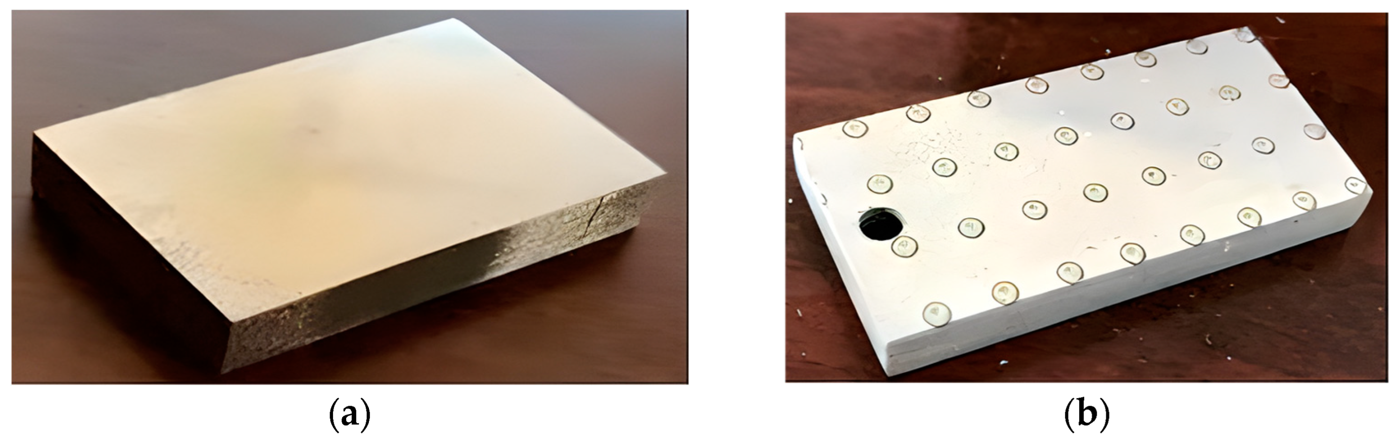
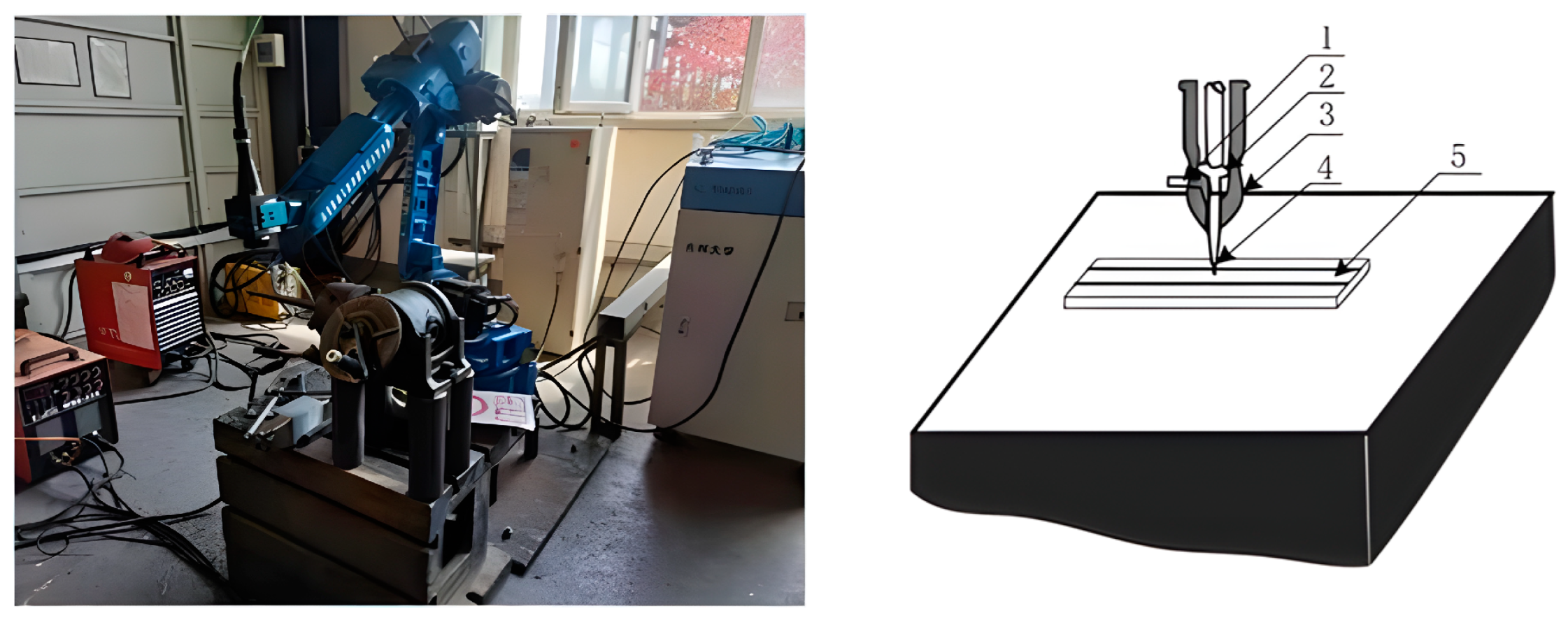
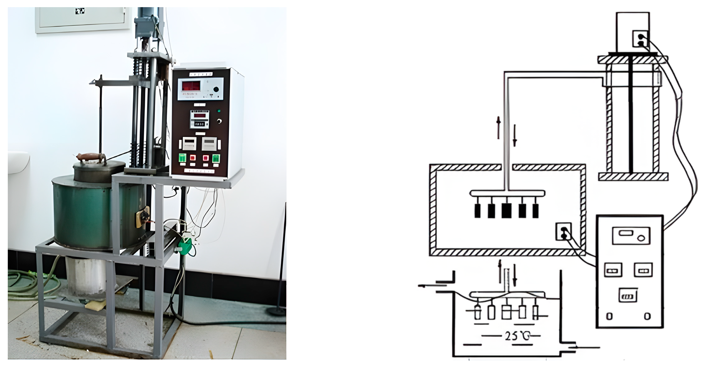
This study aims to investigate the impact of bionic brake drum surface morphology on wear and thermal fatigue performance, analyze the friction and wear relationship between brake drums and pads, and evaluate their performance at various temperatures. The innovation of this study is that firstly, a design laser processing method of bionic brake drum is proposed, and then the mutual influence between different processed pattern bionic brake drums and different material brake pads is analyzed through sample production and wear experiments. The performance of bionic brake drums is compared with that of traditional brake drums by conducting bench tests, which further verifies the superiority of bionic brake drums in terms of performance and, therefore, provides new ideas for the optimized matching of bionic brake drums and brake pads from the perspective of improving the service life of the braking system.

2. Brake Drums and Test Plan Design

2.1. Brake Drums and Brake Pads Preparation

2.1.1. Brake Drum Specimen Preparation

This test utilized cast iron automotive brake drum material, specifically the HT250 grade provided by FAW Group (Changchun, China) for heavy trucks. The microstructure of the brake drum was observed using an LEXT-OLS 3000 OLYMPUS 3D laser confocal microscope (OLYMPUS, Tokyo, Japan). The microstructural composition of this cast iron material is presented in Figure 1.
The graphite type primarily consists of Type A, accompanied by a minor proportion of Type B flake graphite, as depicted in Figure 1a. The matrix organization is predominantly pearlite, accounting for over 90% of the composition, with a small amount of ferrite present, as illustrated in Figure 1b,c. The primary chemical compositions are outlined in Table 1.
The brake drum was cut into rectangular specimens measuring 40 × 20 × 5 mm. Figure 2 shows the brake drum specimens before and after the treatment.

2.1.2. Pairing Brake Pads Specimen Preparation

The three most frequently utilized brake pad types were chosen for grinding against the brake drum specimens. These included the semi-metallic brake pad, the non-asbestos organic (NAO) brake pad, and the ceramic brake pad, as depicted in Figure 3.
The semi-metallic, ceramic, and NAO brake pads were machined into rectangular specimens, each measuring 120 × 30 × 10 mm. The microstructures of these specimens are depicted in Figure 4.
The semi-metallic pad displays metallic fibers within a matrix. The NAO pad shows a porous organic matrix with dispersed fibers. The ceramic pad features a dense, uniform structure with ceramic fibers.

2.1.3. Laser-Treated Bionic Brake Drum Preparation

A six-degree-of-freedom robotic arm laser machining system was employed for the processing of the brake drum’s surface, as depicted in Figure 5. To achieve precise control over the laser spot’s out-of-focus amount, the position of the robotic arm in the Z-axis direction was adjusted. Additionally, the output laser parameters of the laser control cabinet were adjusted to ensure uniformity in size, shape, and organization among laser-treated units of the same model.
The experimentally selected laser processing parameters are shown in Table 2.
To form the bionic structure surface on the brake drum, the striped unit brake drum (“scallop” surface feature), the grid unit brake drum (“dragonfly wings” surface feature), and the untreated brake drum were prepared before the bench test, respectively, as shown in Figure 6.

2.2. Specimen Wear Test Bench

The wear tests were carried out on a linear reciprocating wear test bench, with Figure 7 showing a schematic diagram of the wear test bench structure.
The test load was 100 N and the motor speed was 70 r/min. The travelling distance of the connecting rod was 0.07 m for each revolution of the motor. The wear time was set to 10 h (friction travel 2940 m). After the wear test, the cast iron specimen was cleaned with an ultrasonic cleaner, and the abrasive chips on the surface of the brake pad specimen were removed and collected. An electronic balance with an accuracy of 0.001 g was used for weighing. In order to ensure the reliability of the test results, each group of tests was repeated three times, and the average value of weight loss obtained from the three tests was taken as the final test results.

2.3. Brake Drum Thermal Fatigue Test

The thermal fatigue tests were carried out on a resistance-heated, self-contained thermal fatigue test bench, as shown in Figure 8.
The thermal fatigue specimens were suspended from a circular test disc at a uniform height utilizing iron wires. An electric motor facilitated the rotation of the lead screw, thereby enabling the vertical movement of the specimens to accomplish the heating and cooling cycles. The control cabinet and limit switch were employed to regulate the heating and cooling duration as well as the travel of the lead screw, with data being fed back to a counter for the purpose of recording the number of cycles. The test heating temperature was established at 600 °C, whereas the cooling temperature was maintained at room temperature. Each cycle comprised of 3 min of heating and 5 s of cooling. The number of fatigue cycles for the test was determined in accordance with the specified test protocol requirements.

2.4. Experiment Design

The experiment was designed to evaluate the dual effects of thermal fatigue and laser-treated surface unit bodies on the performance of brake drums. Initially, friction tests were performed on brake drums without undergoing thermal fatigue treatment, paired with brake pads, in order to investigate their friction and wear characteristics, and to compare the wear patterns of the brake pads when paired with untreated and laser-treated bionic brake drums. Following this, thermal fatigue tests were conducted on brake drums subjected to varying numbers of cycles, with the aim of assessing the impact of thermal fatigue on the surfaces of the brake drums through the analysis of crack quantity and size. Subsequently, these thermally fatigued brake drums were paired with brake pads for wear tests, to evaluate the effect of thermal fatigue on their friction and wear performance. Finally, the analyzed results were verified through thermal fatigue bench testing to ensure the accuracy and correctness of the findings.

3. Mechanical Analysis of Wear Performance of Different Brake Drum Unit Bodies

3.1. Bionic Brake Drum Unit Body Organization and Characteristics

Figure 9 shows the cross-section of different shapes of units formed by laser machining perpendicular to the surface of the bionic brake drum, the white part of which are the units. Macroscopically, the units are dissected, and their cross-sectional shapes are essentially the same, taking the form of a semi-circular body, as shown in Figure 9.
As the laser energy increases, the melting area expands and the unit body size increases accordingly. However, this also increases heat output, slowing the self-cooling rate and leading to an increase in grain size. As shown in Figure 10, the point unit body exhibits the finest microstructure, while the stripe and grid unit body are relatively coarser.
The microhardness of the bionic specimen was measured using a microhardness tester, type 1600-5122 VD MICROMET 5104, manufactured by Buehler, Lake Bluff, IL, USA. The load was 200 g, the loading time was 5 s, and the experimental results were the average of three measurements. The hardness varied with the shape of the unit bodies: the point unit body had a hardness of 659.6 HV, the striped unit body had a hardness of 645.6 HV, and the grid unit body had a hardness of 638.8 HV.

3.2. Mechanical Analysis of Wear of Different Unit Bodies and Brake Pads

3.2.1. Contact Stress and Wear of Point Unit Body on Brake Pads

Assuming that the friction surface between the brake drum and the brake pad is planar and approximating the surface of the point unit body as a sphere, a schematic diagram of the interaction between the point unit body and the brake pad is shown in Figure 11.
Let the spherical radius of the point unit body be ρ, the positive pressure of the unit body perpendicular to the surface of the brake pad be P, and O be the initial contact point between the unit body and the brake pad. The hardness of the unit body is high, and the deformation after the force is negligible; while the hardness of the brake pad is low, and the elastic deformation will be produced under the positive pressure of the unit body, so that the point O will move downward, as shown in Figure 12.
The radius of the contact surface between the unit body and the brake pad is Rc. Let F be the contact stress between the unit body and the brake pad contact surface and make a vertical line downward from the center of the sphere of the unit body as the Z-axis. Considering the symmetry, the contact stress F at any point M on the contact surface is only related to the distance of the point from the Z-axis R1. Q0 is the contact stress between the unit body and the brake pad at the lowest point O of the contact surface.
According to the contact stress distribution in elastic mechanics when a sphere is in contact with a plane, and the Hertz theory of contact mechanics, the contact stress F for a point M on the sphere of contact between a point-like unit body and a brake pad has:
F = Q 0 R c R c 2 R 1 2
Referring to Preston’s equation there is:
Δ Z = 0 t   k ν p n d t
In the expression above, Z represents the amount of friction wear removal, t denotes the time of action between the two components in the friction vice, k refers to the scale factor, v indicates the relative speed of motion between the two components in the friction vice, and P n represents the positive pressure generated by the interaction between the two components in the friction pair.
Referring to Figure 13, there is an M point on the contact surface. The distance between the M and Z axis is the radius which is R1. With the M point, a small microcircle has been considered with the width dR1. Then the pressure dpZ on the two surfaces in the direction of the Z-axis on this small microcircle shall be the product of the contact compressive stress F and its area, that is:
d p z = 2 F π R 1 d R 1
The pressure dpZ in Equation (3) is along the Z-axis, in the vertical direction, while pn in Equation (2) is the normal positive pressure between the two. Since the contact surface between the two is spherical and not horizontal, the tangent plane at point M is at an angle α1 to the horizontal (see Figure 13). Therefore, the direction of pn does not coincide with the direction of dpZ, so the positive pressure pn induced by the pressure dpZ in the vertical direction in Equation (3) in the direction normal to the contact surface should be found out first. Then, the amount of frictional wear produced by this microcircle on the unit for the brake pad should be found out by substituting pn into Equation (2). For this purpose, a local enlargement at point M in Figure 12 is made to obtain Figure 13.
It is obtained from the analysis of Figure 13:
p n = d p z / c o s α 1
Substituting Equation (3) into Equation (4) gives:
p n = 2 F π R 1 d R 1 / c o s α 1
Substituting Equation (5) into Equation (2) gives:
Δ Z 1 = 0 t   2 k ν F π R 1 d R 1 c o s α 1 d t
The ∆Z1 in Equation (6) is the amount of frictional wear generated by this microcircle on the unit for the brake pad, and it is required to find out the wear ∆Z generated by friction on the brake pad by the whole unit at a certain moment t. From Figure 12 shows that the range of variation of R1 is from 0 to RC, such that there is:
Δ Z = 0 t   0 R c   2 k ν F π R 1 c o s α 1 d R 1 d t
This can be seen in Figure 12:
c o s α 1 = ρ 2 R 1 2 ρ
Substituting Equations (1) and (8) into Equation (7) yields:
Δ Z = 0 t   0 R c   2 k ν ρ π Q o R 1 R c 2 R 1 2 R c ρ 2 R 1 2 d R 1 d t
Since the parameters k, ν, ρ, π, Qo, RC, etc. do not vary with R1, for R1 they are equivalent to constants, so let C = kνρπQo/RC, x = R12, and then Equation (9) follows:
Δ Z = 0 t   C 0 R c 2   R c 2 x ρ 2 x d x d t
Integrating Equation (10) over x yields:
Δ Z = 0 t   C ρ 2 x R c 2 x 1 0 R c 2 + ρ 2 + R c 2 2 0 R c 2   d x ρ 2 x R c 2 x d t
= 0 t   C R c ρ + ( R c 2 ρ 2 ) A r t h R c 2 x ρ 2 x 0 R r 2 d t
Δ Z = 0 t   k ν ρ π Q o R c R c ρ + 1 2 ( ρ 2 R c 2 ) l n 1 + R c / ρ 1 R c / ρ d t
According to elastic mechanics, the contact stress at the center of contact between the point-like unit body and the brake pad, and the maximum contact stress Q0 on the contact surface of the two is:
Q 0 = 3 P 2 π R c 2
Substituting Equation (12) into Equation (11) organizes it:
Δ Z = 0 t   k v P 3 ρ 2 R c 3 R c ρ + 1 2 ( ρ 2 R c 2 ) l n 1 + R c / ρ 1 R c / ρ d t
Setting:
D = 3 ρ 2 R c 3 R c ρ + 1 2 ( ρ 2 R c 2 ) l n 1 + R c / ρ 1 R c / ρ
Then, Equation (13) can be changed to:
Δ Z = 0 t   k v P D d t
A comparison of Equations (2) and (15) shows that for positive inter-surface pressures in spherical and planar contact, their magnitude and direction vary with their position on the contact surface. This results in one more term D in Equation (15) than in Equation (2), because k, ν, and P are all greater than 0. Therefore, if D > 1, then ΔZ from Equation (15) is greater than ΔZ from Equation (2), which means that the frictional wear of the unit body of the laser-treated drum on the brake pad is greater than that of the surface of the normal untreated brake drum on the brake pad. The following focuses on analyzing whether D is greater than 1.
Setting:
E = l n 1 + R c / ρ 1 R c / ρ
Then Equation (14) changes to:
D = 3 ρ 2 R c 3 R c ρ + 1 2 ( ρ 2 R c 2 ) E
In the braking process, due to the high modulus of elasticity of both the brake drum and brake pad materials, the elastic deformation of their contact is relatively small, the depth of the unit body pressed into the surface of the brake pad is small, and the radius of the contact surface RC formed by them is also small. Therefore, there is:
R c ρ < 1
Expanding Equation (16) in this way in a power series gives:
E = 2 R c ρ + 1 3 ( R c ρ ) 3 + 1 5 ( R c ρ ) 5 + . . . + 1 2 n + 1 ( R c ρ ) 2 n + 1 + . . .
Considering Equation (18), it can be obtained from equation:
E 2 R c ρ
Substituting Equation (20) into Equation (17) organizes it:
D = 3 ρ 2 R c 3 2 R c ρ R c ρ 3 = 3 2 ( 2 ρ 2 R c 2 1 )
Consider Equation (18) there:
ρ 2 R c 2 > 1
2 ρ 2 R c 2 > 2
2 ρ 2 R c 2 1 > 1
Therefore, according to Equation (21) we have:
D > 1.5
According to Equation (22), comparing Equations (2) and (15), the friction wear on the brake pad by the point unit body of the laser-treated bionic brake drum is more than 50% higher than that of the conventional flat friction wear.

3.2.2. Frictional Wear of Striped Unit Body on Brake Pad

The striped unit body is approximated as part of a cylinder, and the surface of the brake pad remains planar. Referring to Figure 11 and Figure 12, let the radius of the cylindrical surface, the positive pressure, and the initial contact point of the striped unit body remain ρ, P, and O.
The outer contour of the contact surface between the unit body and the brake pad is rectangular, with the long side representing the length of the cylinder and the short side representing the width of the indentation. Considering the symmetry, the width of the indentation is set to be 2RC (see Figure 12). Considering that the length of the striped unit is much larger relative to the width of the indentation, the contact between the striped unit and the brake pad can be regarded as an infinitely long cylinder in contact with a semi-infinite plane. A vertical line is made downward over the axis of the cylinder as the Z-axis, and the contact stress on the contact surface, which varies as a function of the distance R1 from the Z-axis at that point, is a function of R1.
Let P(R1) be the contact stress per unit length between the contact surface of the unit and the brake pad along the axis of the unit, whose direction is downward along the direction of the lead weight. p0 is the contact stress per unit length at the lowest point O of the contact surface of the unit and the brake pad. According to contact mechanics, for a point M on the contact surface of a cylinder, the unit length contact stress P(R1) is given by:
P ( R 1 ) = 2 P π R c 2 R c 2 R 1 2
Refer to Equation (2) and Figure 12, taking the Z-axis as the center and passing through point M on the contact surface between the two, at a distance R1 from the Z-axis, a small micro-element is taken with a width of dR1. The unit length pressure dpZ along the Z-axis direction on the cylindrical surface at this micro-element should be the product of the unit length contact stress P(R1) and its width, that is:
d p z = P ( R 1 ) d R 1
Substituting Equation (23) into Equation (24) yields:
d p z = 2 P π R c 2 R c 2 R 1 2 d R 1
The pressure dpZ in Equation (25) is along the Z-axis, in the direction of the lead hammer used in the experiment, whereas the pressure pn of the two interacting in the friction pair in Equation (2) is the normal positive pressure between the two. The pressure dpZ in the direction of the lead hammer in Equation (25) is used to find the positive pressure pn induced in the direction normal to the contact surface, which is then substituted into Equation (2) to find the amount of frictional wear generated by this microelement on the unit for the brake pad. Substituting Equations (8) and (25) into Equation (4) yields:
In Equation (25), the pressure dpZ is along the Z-axis, in the vertical direction, while in Equation (2), the pressure pn in the friction pair is the normal pressure between the two. The normal pressure pn on the contact surface caused by the vertical pressure dpZ from Equation (25) is calculated. Then, it is substituted into Equation (2) to find the friction and wear amount on the brake pad caused by this micro-element on the unit. By substituting Equations (8) and (25) into Equation (4):
p n = 2 P ρ π R c 2 R c 2 R 1 2 ρ 2 R 1 2 d R 1
Substituting Equation (26) into Equation (2) gives:
Δ Z 1 = 0 t   2 k ν P ρ π R c 2 R c 2 R 1 2 ρ 2 R 1 2 d R 1 d t
To calculate the wear ∆Z produced by the entire striped unit body on the brake pad at a certain moment t, it is necessary to integrate Equation (27) with respect to dR1. Referring to Figure 13 and considering symmetry, the formula is setup below:
Δ Z = 0 t   4 k v P ρ π R c 2 0 R c   1 1 R c 2 / ρ 2 1 R 1 2 / ρ 2 d R 1 d t
Considering that the brake pad is more rigid and its elastic deformation is smaller, the R12/ρ2 term in Equation (28) can be ignored. In addition, considering that Rc > 0 and ρ > 0, so that Equation (28) becomes:
Δ Z = 0 t   4 k ν P ρ π R c 2 0 R t   R c ρ d R 1 d t
Integrating Equation (29) over R1 yields:
Δ Z = 0 t   4 k v P π d t
Comparing Equations (2) and (30), it is shown that an increase in frictional wear on the brake pad caused by the striped unit body is 4/π times the wear of the original flat surface, which is about 27%.

4. Wear Patterns of Different Brake Drum Unit Bodies and Brake Pad

4.1. Wear Performance Analysis of Different Brake Drum Unit Bodies

Wear tests were conducted with different shaped brake drums against semi-metallic, NAO, and ceramic brake pad specimens. As shown in Table 3, untreated brake drums have much greater wear than laser-treated drums and cause less wear effect on to brake pads than laser-treated drums. Among laser-treated bionic brake drums, those with point unit body exhibited the highest self-wear but caused the least wear to the brake pad; in contrast, those with a grid unit body showed the lowest self-wear but caused the most wear to the brake pad.
To characterize the effect of laser-treated bionic brake drum specimen on the wear of brake pads, the wear increment change of the brake pad, denoted as W∆, is proposed. This is defined as the change in wear volume of the brake pad corresponding to a 1% improvement in wear resistance of the laser-treated bionic brake drum relative to the untreated brake drum specimens. The expression is defined as:
w = s N f
where Δs is the increment of brake pad wear, which is
s = f ω
where Δf is the wear amount of the paired brake pad for the laser-treated bionic brake drum specimen and Δ ω is the wear amount of the paired brake pad for the untreated brake drum specimen. N f is the wear resistance of the laser-treated bionic brake drum specimen relative to the untreated specimen, which is:
N f = W ω W f W ω
where W ω is the wear amount of the untreated brake drum specimen and W f is the wear amount of the laser-treated bionic brake drum specimen. The larger the value of W∆, the more severe the wear of the brake drum on the brake pad and the worse the wear coordination of the brake drum when the wear resistance increases equally.
As shown in Table 4, compared to the untreated brake drum specimen, the brake pad wear caused by the laser-treated bionic brake drum specimen is more obvious. The brake pad wear caused by point unit body is relatively less, the grid unit body wear is the maximum, and the striped unit body wear is in the middle.

4.2. Wear Morphology Analysis of Different Brake Drum Units

The morphology of worn friction discs was observed in three dimensions using an LEXT-OLS 3000 OLYMPUS 3D laser confocal microscope. As shown in Figure 14, the wear surface of the brake pad caused by the specimen of the point unit body is relatively flat, and the surface has less pits and less spalling. Compared with different types of brake pad wear morphology, the wear surface of NAO brake pad was the roughest, followed by semi-metal type, and the lightest was the ceramic brake pad.
As shown in Figure 15, the wear surface of the brake pad caused by the striped unit body specimen was relatively severe with larger pits and spalling.
As shown in Figure 16, the wear surface of the brake pad caused by the grid unit body specimen has severe spalling with large craters and surface tears, exhibiting the characteristics of severe wear.
Comparing the wear morphology of different types of brake pad, the NAO brake pad showed the most severe surface wear, followed by the semi-metallic-type, while the lightest was the ceramic-type brake pad. The wear of the brake pad was greater for the grid unit body than for the striped unit body, and for the striped unit body than for the point unit body.

5. Analysis of Thermal Fatigue Performance of Brake Drums with Different Unit Bodies

To gain a deeper understanding of the wear characteristics of various unitary bionic brake drums, this study performed a bench wear test on the brake drums. The test was conducted using a bench test machine, as shown in Figure 17.

5.1. Effect of Thermal Cycling on the Wear Performance of Brake Drums with Different Unit Bodies

Table 5 shows that brake pad wear decreases and brake drum wear increases when compared to the non-heat fatigued drum; as the number of heat fatigue cycles increases, drum wear continues to increase, while brake pad wear continues to decrease.
After thermal fatigue treatment, cracks formed on the surface of the brake drum specimen, and these cracks divided the surface into small independent surfaces, and the bumps or abrasive particles of the brake pad formed a ploughing wear on the surface of the brake drum during friction. On the other hand, thermal fatigue treatment led to a decrease in the hardness of the brake drum matrix, while the hardness of the brake pad remained constant. Under the same friction conditions, the wear of the brake drum matrix increased, while the wear of the brake pad decreased. With the increase in the number of thermal fatigues, this trend is more obvious.
In contrast, the laser-treated brake drum specimens showed less variation in wear resistance because the units on the laser-treated surface are free of graphite and had fewer thermal fatigue cracks. The brake drum with the grid unit body showed the best wear resistance, with a reduction of about 42% in wear compared to the untreated brake drum, but also caused the most severe wear to the brake pad.

5.2. Analysis of Thermal Fatigue Cracking of Brake Drums with Different Unit Bodies

5.2.1. Crack Analysis of Thermal Fatigue Specimens

Table 6 shows the variation in the longest crack length and the number of cracks on the surface of the brake drum specimens with different numbers of thermal fatigue cycles. After 150 thermal cycles, both the untreated brake drum specimen and the point unit body brake drum specimen had cracks longer than 2 mm on the surface, but the longest crack size of the point unit body brake drum specimen was nearly 45% shorter than that of the untreated brake drum specimen, and the cracks of the striped and grid unit body brake drum specimens were not more than 2 mm. As the number of thermal fatigue cycles increased, both the longest crack length and the number of surface cracks are increased. However, the longest crack length and the number of surface cracks on the laser-treated brake drum specimens were less than those on the untreated brake drum specimens. After 600 thermal cycles, the longest crack length in the laser-treated grid unit body brake drum was only half that of the untreated brake drum, a reduction of 50%; the number of cracks longer than 2 mm was also reduced by 52.4% compared to the untreated brake drum. To summarize, the laser-treated unit bodies played a significant role in suppressing crack initiation and propagation, with the grid unit body being the most effective, followed by the striped unit body, and the point unit body being the least effective.

5.2.2. Crack Analysis After Thermal Fatigue Bench Test

In the bench test, the direction of the brake drum unit arrangement was chosen to be at an angle of 45 degrees with the friction direction, the shape of the unit body was chosen to be two kinds of stripes and grids, the spacing of the unit was set to be 50 mm, the parameters of the laser processing were selected according to the instructions in Table 1, and the test was conducted using the same batch of the enterprise’s production of the drums, the brake pad of the friction pair were semi-metallic pads produced by the Tepic friction material company. The paired brake pads were semi-metallic brake pads produced by Tebic.
Figure 18, Figure 19, Figure 20, Figure 21, Figure 22, Figure 23 and Figure 24 show photographs of the surface of the brake drums taken when each brake drum was removed from the test bench for inspection after different numbers of braking cycles.
After 200 cycles of testing, fatigue cracks were observed on all specimen surfaces. The brake drums without laser treatment showed longer and more numerous cracks compared to those with laser treatment. There was no significant difference between the crack patterns of the striped and grid pattern laser-treated bionic brake drums.
After 240 fatigue tests, the brake drums without laser treatment had significantly more and longer cracks than those with laser-treated ones. The differences between the striped and grid pattern laser-treated bionic brake drums remained subtle.
After 280 fatigue tests, the brake drums without laser treatment have far more and longer cracks than those with laser treatment. The crack propagation for the striped pattern laser-treated bionic brake drum is faster than in the grid pattern one.
The results of the 320 fatigue tests are similar to those of the 280 tests, with more pronounced cracking, as shown in Figure 21.
After 360 fatigue tests, the extension of cracks was more serious. After 370 fatigue tests of the brake drum without laser treatment, cracks penetrated through the specimen and test was finished, as shown in Figure 22.
After 400 fatigue tests, the crack length of the striped pattern laser-treated bionic brake drum was larger than that of the grid pattern one.
Eventually, the striped pattern laser-treated bionic brake drum failed after then 470 fatigue test and the grid pattern one failed after the 510 fatigue tests with penetrating cracks, and the round of test was completed.

5.3. Brake Drum Thermal Fatigue Test Results

Bench test results indicate that, compared to untreated brake drum, the fatigue life of the striped pattern laser-treated bionic brake drum increased by 27%, and that of the grid pattern increased by 38%. The laser-treated bionic brake drum not only significantly extends its service life but also ensures reliable braking performance. As shown in Table 7, the braking torque of the laser-treated bionic brake drum exceeds that of the untreated brake drum, with the grid pattern laser-treated bionic brake drum showing higher torque than the striped pattern one. At a vehicle speed of 60 km/h, the braking torque of the striped pattern laser-treated bionic brake drum increased by 5% compared to the untreated brake drum, while that of the grid pattern one increased by 9.5%.
The bench test was performed to compare the wear effect on brake pads between the laser-treated and untreated brake drum. As shown in Table 8, it is indicated that the wear volume of the laser-treated bionic brake drums is reduced by 58% for the striped pattern and 62% for the grid pattern brake drum compared to the untreated brake drum. However, the wear on the brake pad increased by 79% for the striped pattern and 111% for the grid pattern.

6. Conclusions

This study designed a laser-treated bionic brake drum with various unit bodies processed on the drum surface and established a corresponding contact mechanics model. This study investigated the impact of different unit bodies on the friction and wear of the brake pad, theoretically finding that the point unit body increased friction wear by more than 50%, while the striped unit body caused an increase of about 27%, which thereby lays the foundation for the optimized design of bionic brake drums.
This study investigated the effects of unit body patterns and temperature on the wear of laser-treated bionic brake drums and corresponding brake pads. It was found that the unit bodies formed by laser processing on the brake drum surface increased the average hardness and improved wear resistance. Test results showed that bionic brake drums with a point unit body had the highest self-wear but the least impact on brake pad wear, and those with a grid unit body had the lowest self-wear but the greatest impact on brake pad wear. Experiments conducted by varying temperatures revealed the friction coefficient variation patterns of different materials with temperature, providing a reference for bionic brake drum design.
For the first time, this study systematically evaluated the thermal fatigue resistance and wear resistance of different unit bodies, with the grid unit body showing the best performance and the point unit body the worst. It was indicated from the test bench that the laser-treated bionic brake drums had 58% less self-wear (striped pattern) and 62% less self-wear (grid pattern) compared to untreated brake drums, but they caused 79% more wear to the friction pads (striped pattern) and 111% more wear (grid pattern). This requires that the wear of brake pads must be taken into account when designing the bionic brake drum.
In fact, the increase in the wear of the friction surface will increase the friction force between the friction surfaces. The increase in friction force will increase the heat generated between the friction surfaces and raise the temperature of the friction surfaces. The rise in temperature, in turn, exacerbates the wear between the friction surfaces, thus forming a vicious cycle. Therefore, reducing friction wear is very important, and further research should continue to explore ways to reduce the wear of the brake drum and brake pad.

Author Contributions

Conceptualization, H.Y. and T.Z.; methodology, H.Y., Y.Z. and T.Z.; software, W.L.; validation, W.L., H.Y. and H.X.; formal analysis, W.L. and H.X.; investigation, W.L.; resources, H.Y. and T.Z.; data curation, Y.Z. and T.Z.; writing—original draft preparation, W.L.; writing—review and editing, W.L., H.Y. and Y.Z.; visualization, H.X.; supervision, H.Y. and Y.Z.; project administration, H.Y.; funding acquisition, H.Y. and H.X. All authors have read and agreed to the published version of the manuscript.

Funding

This research was funded by the Public Welfare Research Program of Jiaxing City, grant number 2024AY10033; Scientific Research Fund of Zhejiang Provincial Education Department, grant number Y202352270. 2024 Fundamental Research Project of the Educational Department of Liaoning Province, grant number LJ212410154031. 2024 Jiaxing City Key R&D Program: 2024BZ10001. 2024 Jiaxing City Public Welfare Research Program: 2024AY10034.

Data Availability Statement

The original contributions presented in the study are included in the article, further inquiries can be directed to the corresponding authors.

Conflicts of Interest

The authors declare no conflict of interest.

References

  1. Yuan, Y.; Zhao, G.; Zhang, P.; Zhou, H. Effects of shapes of biomimetic coupling units on wear resistance of 7075 aluminum alloy. Opt. Laser Technol. 2020, 121, 105786. [Google Scholar] [CrossRef]
  2. Sysaykeo, D.; Linares, J.M.; Mermoz, E. Wear Behavior of a Bio-inspired Bearing for off-center Loads. J. Bionic Eng. 2020, 6, 1251–1262. [Google Scholar] [CrossRef]
  3. Shankar, S.; Nithyaprakash, R.; Sugunesh, P.; Uddin, M.; Pramanik, A. Contact Stress and Wear Analysis of Zirconia Against Alumina for Normal and Physically Demanding Loads in Hip Prosthesis. J. Bionic Eng. 2020, 5, 1045–1058. [Google Scholar] [CrossRef]
  4. Zhang, H.; Zhang, P.; Sui, Q.; Zhao, K.; Zhou, H.; Ren, L. Influence of multiple bionic unit coupling on sliding wear of laser-processed gray cast iron. J. Mater. Eng. Perform. 2017, 26, 1614–1625. [Google Scholar] [CrossRef]
  5. Pang, X.; Gu, Z.; Zhang, P.; Zhou, H. Study on laser prepared reinforcement unit distribution of large scale non-uniform hardness surface of gray cast iron against wear. Mater. Res. Express 2023, 10, 106509. [Google Scholar] [CrossRef]
  6. Tong, X.; Zhou, H.; Ren, L.Q.; Zhang, Z.H.; Cui, R.D.; Zhang, W. Thermal fatigue characteristics of gray cast iron with non-smooth surface treated by laser alloying of Cr powder. Surf. Coat. Technol. 2008, 202, 2527–2534. [Google Scholar] [CrossRef]
  7. Zhang, Z.; Lin, P.; Zhou, H.; Ren, L. Microstructure, hardness, and thermal fatigue behavior of H21 steel processed by laser surface remelting. Appl. Surf. Sci. 2013, 276, 62–67. [Google Scholar] [CrossRef]
  8. Pang, Z.; Zhou, H.; Zhang, P.; Cong, D.; Meng, C.; Wang, C.; Ren, L. Study on quantitative relation between characteristics of striature bionic coupling unit and wear resistance of gray cast iron. Appl. Surf. Sci. 2015, 331, 179–184. [Google Scholar] [CrossRef]
  9. Li, H.; Zhou, H.; Zhang, D.P.; Zhang, P.; Zhou, T. Influence of varying distribution distance and angle on fatigue wear resistance of 40Cr alloy steel with laser bionic texture. Mater. Chem. Phys. 2022, 277, 125515. [Google Scholar] [CrossRef]
  10. Yu, D.; Zhou, T.; Zhou, H.; Zhang, P.; Yan, Y. Effects of Pearlite on Thermal Fatigue and Wear Resistance of Gray Cast Iron Treated by Laser [DB/OL]. J. Mater. Eng. Perform. 2022, 31, 3962–3974. [Google Scholar] [CrossRef]
  11. Zhao, G.; Yuan, Y.; Zhang, P.; Zhou, T.; Wang, H.; Li, X.; Zhou, H. Effect of hardness gradient of laser bionic coupling unit on wear resistance of 6082 aluminum alloy. Opt. Laser Technol. 2022, 153, 108172. [Google Scholar] [CrossRef]
  12. Marko, T. Energy thrift and improved performance achieved through novel railway brake discs. Appl. Energy 2008, 34, 317–324. [Google Scholar]
  13. Gwoździk, M. Corrosion of a chimney liner operated for 130,000 hours. J. Min. Metall. Sect. B Metall. 2023, 59, 269–277. [Google Scholar] [CrossRef]
  14. Blessley, S.D.; Narayanasamy, P.; Balasundar, P.; Balavairavan, B. Effect of Voltage and concentration of polyetherimide on surface morphology and corrosion properties of AZ91D by electro-spin coating. Heliyon 2024, 10, e31884. [Google Scholar] [CrossRef]
  15. Xin, T.; Hong, Z.; Li, C.; Zhi-hui, Z.; Lu-quan, R. Effects of C content on the thermal fatigue resistance of cast iron with biomimetic non-smooth surface. Int. J. Fatigue 2008, 30, 1125–1133. [Google Scholar] [CrossRef]
  16. Collini, L.; Nicoletto, G.; Konečná, R. Microstructure and mechanical properties of pearlitic gray cast iron. Mater. Sci. Eng. A 2008, 488, 529–539. [Google Scholar] [CrossRef]
  17. Liu, T.Y.; Qu, W.; Su, Y. TiC Reinforcement Composite Coating Produced Using Graphite of the Cast Iron by Laser Cladding. Materials 2016, 9, 815. [Google Scholar] [CrossRef]
  18. Zhang, P.; Yan, H.; Yao, C.; Li, Z.; Yu, Z.; Xu, P. Synthesis of Fe–Ni–B–Si–Nb amorphous and crystalline composite coatings by laser cladding and remelting. Surf. Coat. Technol. 2011, 206, 1229–1236. [Google Scholar] [CrossRef]
  19. Pang, Z.; Zhou, H.; Xie, G.; Cong, D.; Meng, C.; Ren, L. Effect of bionic coupling units’ forms on wear resistance of gray cast iron under dry linear reciprocating sliding condition. Opt. Laser Technol. 2015, 70, 89–93. [Google Scholar] [CrossRef]
  20. Chen, Z.K.; Lu, S.C.; Song, X.B.; Zhang, H.; Yang, W.S.; Zhou, H. Effects of bionic units on the fatigue wear of gray cast iron surface with different shapes and distributions. Opt. Laser Technol. 2015, 66, 166–174. [Google Scholar] [CrossRef]
  21. Yang, W.; Zhou, H.; Sun, L.; Wang, C.; Chen, Z. Effect of biomimetic coupling units’ morphologies on rolling contact fatigue wear resistance of steel from machine tool rolling tracks. Opt. Laser Technol. 2014, 57, 175–180. [Google Scholar] [CrossRef]
  22. Sui, Q.; Zhou, H.; Bao, H.; Zhang, P.; Yuan, Y.; Meng, C. Wear behavior of quenched iron with various shapes and unit processed through two-step laser alloying of C powder. Opt. Laser Technol. 2018, 114, 103–111. [Google Scholar] [CrossRef]
  23. Chen, Z.K.; Zhou, T.; Zhang, H.F.; Yang, W.S.; Zhou, H. Influence of orientations of bionic unit fabricated by laser remelting on fatigue wear resistance of gray cast iron. J. Mater. Eng. Perform. 2015, 24, 2511–2520. [Google Scholar] [CrossRef]
  24. Su, W.; Zhou, T.; Zhang, P.; Zhou, H.; Li, H. Effect of distribution of striated laser hardening tracks on dry sliding wear resistance of biomimetic surface. Opt. Laser Technol. 2018, 98, 281–290. [Google Scholar] [CrossRef]
  25. Su, W.; Zhou, T.; Sui, Q.; Zhang, P.; Zhou, H.; Li, H.; Zhang, Z.H. Study on the relationship between intervals among laser stripes and the abrasion resistance of biomimetic laser textured surfaces. Opt. Laser Technol. 2018, 104, 216–224. [Google Scholar] [CrossRef]
  26. Yu, D.; Zhou, T.; Zhou, H.; Xu, Y.; Zhang, P.; Yan, Y. Effects of angle formation between melted zone and friction direction on thermal fatigue and wear resistance of truck drum brake. Proc. Inst. Mech. Eng. Part D J. Automob. Eng. 2021, 235, 1297–1307. [Google Scholar] [CrossRef]
  27. Askerov, S.A. Model of Crack Initiation in a Brake Drum. J. Frict. Wear 2020, 41, 463–469. [Google Scholar] [CrossRef]
  28. Travaglia, C.A.P.; de Castro, J.A.; Lopes, L.C.R.; da Silva Terra, C. An Investigation of the Parameters for Characterization and Prediction of Wear of Drum Brake Friction Material. J. Mater. Eng. Perform. 2022, 31, 5712–5725. [Google Scholar] [CrossRef]
  29. Wang, J.; Zafar, M.Q.; Chen, Y.; Zuo, L.; Zhang, X.; Xie, P.; Zhao, H. Numerical simulation and mechanism analysis of thermal fatigue crack for low-alloy steel brake disc of high-speed train. Int. J. Rail Transp. 2023, 12, 944–957. [Google Scholar] [CrossRef]
  30. Yu, D.; Zhou, T.; Zhou, H.; Bo, H.; Lu, H. Non-single bionic coupling model for thermal fatigue and wear resistance of gray cast iron drum brake. Opt. Laser Technol. 2019, 111, 781–788. [Google Scholar] [CrossRef]
  31. Wang, Z.; Liu, X.; Dong, C.; Chen, J.; Liu, L. Thermal Fatigue Crack Propagation Process and Mechanism of Multicomponent Al-7Si-0.3 Mg Alloy. Crystals 2023, 13, 1068. [Google Scholar] [CrossRef]
  32. Sathish, K.T.; Maniraj, J.; Thangarasu, V.S. Study of friction, wear and plastic deformation of automotive brake disc subjected to thermo-mechanical fatigue. Matéria 2023, 28, e20220329. [Google Scholar] [CrossRef]
  33. Khatir, T.; Bouchetara, M.; Derrar, K.; Djafri, M.; Khatir, S.; Wahab, M.A. Thermomechanical behavior of brake drums under extreme braking conditions. CMC-Comput. Mater. Contin. 2022, 72, 2259–2273. [Google Scholar] [CrossRef]
  34. Liu, Y.; Wang, Y. Fractal analysis of thermal fatigue crack growth behavior in bionic units of vermicular cast iron. Anti-Corros. Methods Mater. 2022, 69, 217–223. [Google Scholar] [CrossRef]
  35. Yin, X.; Zhang, S.; Guo, F.; Pang, Z.; Rong, Y.; Zhang, B. Thermal stress simulation and fatigue life of commercial vehicle disk brakes under emergency braking conditions. AIP Adv. 2023, 13. [Google Scholar] [CrossRef]
  36. Miao, S.S.; Sun, S.C.; Wang, L.; Zhang, P. Effect of Bionic Units Fabricated by WC-NiCrBSiFe Laser Cladding on High-Temperature Erosion Wear Resistance of 304 Stainless Steel. Strength Mater. 2024, 56, 144–154. [Google Scholar] [CrossRef]
  37. Zhao, Y.; Ren, L.Q.; Tong, X.; Zhou, H.; Chen, L. Frictional wear and thermal fatigue behaviours of biomimetic coupling materials for brake drums. J. Bionic Eng. 2008, 5, 20–27. [Google Scholar] [CrossRef]
  38. Macek, W.; Kopec, M.; Laska, A.; Kowalewski, Z.L. Entire fracture surface topography parameters for fatigue life assessment of 10H2M steel. J. Constr. Steel Res. 2024, 221, 108890. [Google Scholar] [CrossRef]
  39. Macek, W.; Branco, R.; de Jesus, J.; Costa, J.D.; Zhu, S.P.; Masoudi Nejad, R.; Gryguć, A. Strain energy density and entire fracture surface parameters relationship for LCF life prediction of additively manufactured 18Ni300 steel. Int. J. Damage Mech. 2024, 33, 10567895241245879. [Google Scholar] [CrossRef]
Figure 1. Material organization of cast iron brake drums. (a) Graphite organization of cast iron; (b) matrix organization of cast iron; (c) pearlite organization of cast iron.
Metals 15 00124 g001
Figure 2. Photograph of a brake drum cut specimen. (a) Untreated brake drum specimen; (b) laser-treated brake drum specimen.
Metals 15 00124 g002
Figure 3. Brake pads matched with the brake drum for wear experiments. (a) Semi-metallic brake pad; (b) NAO brake pad; (c) ceramic brake pad.
Metals 15 00124 g003
Figure 4. Microstructure of brake pads matched with the brake drum for wear experiments. (a) Semi-metallic brake pad; (b) NAO brake pad; (c) ceramic brake pad.
Metals 15 00124 g004
Figure 5. Laser processing system and schematic diagram of the processing. Note: 1. Protective gas, 2. focusing lens, 3. nozzle system, 4. focusing point, 5. processed specimen.
Metals 15 00124 g005
Figure 6. Brake drum before bench testing. (a) Striped unit brake drum; (b) grid unit brake drum; (c) untreated brake drum.
Metals 15 00124 g006
Figure 7. Schematic diagram of linear reciprocating sliding friction wear test bench. Note: 1. Motor runner, 2. linkage mechanism, 3. load, 4. brake drum specimen, 5. brake pad specimen, 6. friction direction.
Metals 15 00124 g007
Figure 8. Resistance heated self-contained thermal fatigue test bench.
Metals 15 00124 g008
Figure 9. Section-cut of each shaped unit body. (a) Point unit body profile; (b) striped unit body profile; (c) grid unit body profile.
Metals 15 00124 g009
Figure 10. Microstructure of different shapes of unit bodies. (a) Point unit body; (b) striped unit body; (c) grid unit body.
Metals 15 00124 g010
Figure 11. Schematic diagram of the interaction between the point unit body and the brake pad.
Metals 15 00124 g011
Figure 12. Schematic diagram of deformation of brake pad under the action of the unit body.
Metals 15 00124 g012
Figure 13. Schematic diagram of enlarged force at any contact point.
Metals 15 00124 g013
Figure 14. Wear morphology of the point unit body with different brake pads.
Metals 15 00124 g014
Figure 15. Wear morphology of the striped unit body with different brake pads.
Metals 15 00124 g015
Figure 16. Wear morphology of the grid unit body units with different brake pads.
Metals 15 00124 g016
Figure 17. Bench testing machine. (a) Testing of Components, (b) Test Bench Drive System.
Metals 15 00124 g017
Figure 18. Surface cracking of each brake drum after 200 braking cycles in the bench tests. (a) Striped pattern brake drum; (b) grid pattern brake drum; (c) untreated brake drum.
Metals 15 00124 g018
Figure 19. Surface cracking of each brake drum after 240 braking cycles in the bench tests. (a) Striped pattern brake drum; (b) grid pattern brake drum; (c) untreated brake drum.
Metals 15 00124 g019
Figure 20. Surface cracking of each brake drum after 280 braking cycles in the bench tests. (a) Striped pattern brake drum; (b) grid pattern brake drum; (c) untreated brake drum.
Metals 15 00124 g020
Figure 21. Surface cracking of each brake drum after 320 braking cycles in the bench tests. (a) Striped pattern brake drum; (b) grid pattern brake drum; (c) untreated brake drum.
Metals 15 00124 g021
Figure 22. Surface cracking of each brake drum after 360 braking cycles in the bench tests. (a) Striped pattern brake drum; (b) grid pattern brake drum; (c) untreated brake drum.
Metals 15 00124 g022
Figure 23. Surface cracking of each brake drum after 400 braking cycles in the bench tests. (a) Striped pattern brake drum; (b) grid pattern brake drum.
Metals 15 00124 g023
Figure 24. Photographs of the failure of each brake drum after different braking cycle times in the bench tests. (a) Photograph of striped unit laser-treated brake drum failure after 470 braking cycles; (b) photograph of grid unit laser-treated brake drum failure after 510 braking cycles; (c) photograph of untreated brake drum failure after 370 braking cycles.
Metals 15 00124 g024
Table 1. Chemical composition of HT250 (Wt.%).
ElementCSiMnPSCuCrFe
Content3.411.610.960.020.010.3150.180Bal.
Table 2. Table of laser processing parameters.
ParametersAmpsPulse WidthFrequencyDefocusing AmountSpeedSpot Diameter
Numerical value115 A6 ms20 Hz4.2 mm2 mm/s1.05 mm
Table 3. Wear of dynamic drums and brake pads for different shaped unit systems (mg).
ModelSemi-MetallicNAOCeramics
Brake Drum WearBrake Pad WearBrake Drum WearBrake Pad WearBrake Drum WearBrake Pad Wear
Untreated12.313.69.319.115.39.6
Point7.222.87.825.411.913.2
Striped6.525.56.530.29.819.7
Grid5.327.25.636.67.520.2
Table 4. Change in incremental brake pad wear for 1% increase in wear resistance of laser-treated bionic brake drum WΔ.
TypeSemi-Metal (mg)NAO (mg)Ceramics (mg)
point unit body0.2220.3690.162
striped unit body0.2390.3910.208
grid unit body0.2520.4460.273
Table 5. Wear of brake drums and semi-metallic brake pads after different numbers of thermal fatigue cycles (mg).
150 Thermal Fatigue Cycles300 Thermal Fatigue Cycles450 Thermal Fatigue Cycles600 Thermal Fatigue Cycles
TypeBrake Drum WearBrake Pad WearBrake Drum WearBrake Pad WearBrake Drum WearBrake Pad WearBrake Drum WearBrake Pad Wear
Untreated17121810.52010.2249.6
Point131914.517.516.716.818.115.8
Striped11221420.415.518.916.517.4
Grid9241023.112221421.3
Table 6. Variation of surface cracks with the number of thermal fatigue cycles for brake drum specimens.
150 Thermal Fatigue Cycles300 Thermal Fatigue Cycles450 Thermal Fatigue Cycles600 Thermal Fatigue Cycles
TypeNumber of Cracks over 2 mm in Length (Strips)Maximum Crack Length (mm)Number of Cracks over 2 mm in Length (Strips)Maximum Crack Length (mm)Number of Cracks over 2 mm in Length (Strips)Maximum Crack Length (mm)Number of Cracks over 2 mm in Length (Strips)Maximum Crack Length (mm)
Untreated17 4.524733164220
Point92.51642493114
Striped72133.51972511.5
Grid32731462010
Table 7. Corresponding braking torques for brake drums (torque unit: kN·m).
Type40 km/h60 km/h
Untreated17.1315.34
Striped pattern laser-treated drum17.5116.1
Grid pattern laser-treated drum18.316.8
Table 8. Wear of the brake drums and on the corresponding brake pads (weight unit: g).
TypeBrake Pad WearBrake Drum Wear
Untreated6250
Striped pattern laser-treated drum11121
Grid pattern laser-treated drum13119
Disclaimer/Publisher’s Note: The statements, opinions and data contained in all publications are solely those of the individual author(s) and contributor(s) and not of MDPI and/or the editor(s). MDPI and/or the editor(s) disclaim responsibility for any injury to people or property resulting from any ideas, methods, instructions or products referred to in the content.

