Article

On the Effect of Multi-Pass Friction Stir Processing on Microstructure-Tensile Deformation Behavior Relationships in Cast Al-7%Si-0.4%Mg Specimens

by
Murat Tiryakioğlu
1,*,
Nelson Netto
2,† and
Paul D. Eason
2
1
School of Engineering and Technology, Jacksonville University, Jacksonville, FL 32211, USA
2
School of Engineering, University of North Florida, Jacksonville, FL 32224, USA
*
Author to whom correspondence should be addressed.
Current address: Saint-Gobain Omniseal Solution, 2550 Antwerp, Belgium.
Metals 2025, 15(12), 1309; https://doi.org/10.3390/met15121309
Submission received: 27 September 2025 / Revised: 18 November 2025 / Accepted: 24 November 2025 / Published: 28 November 2025

Abstract

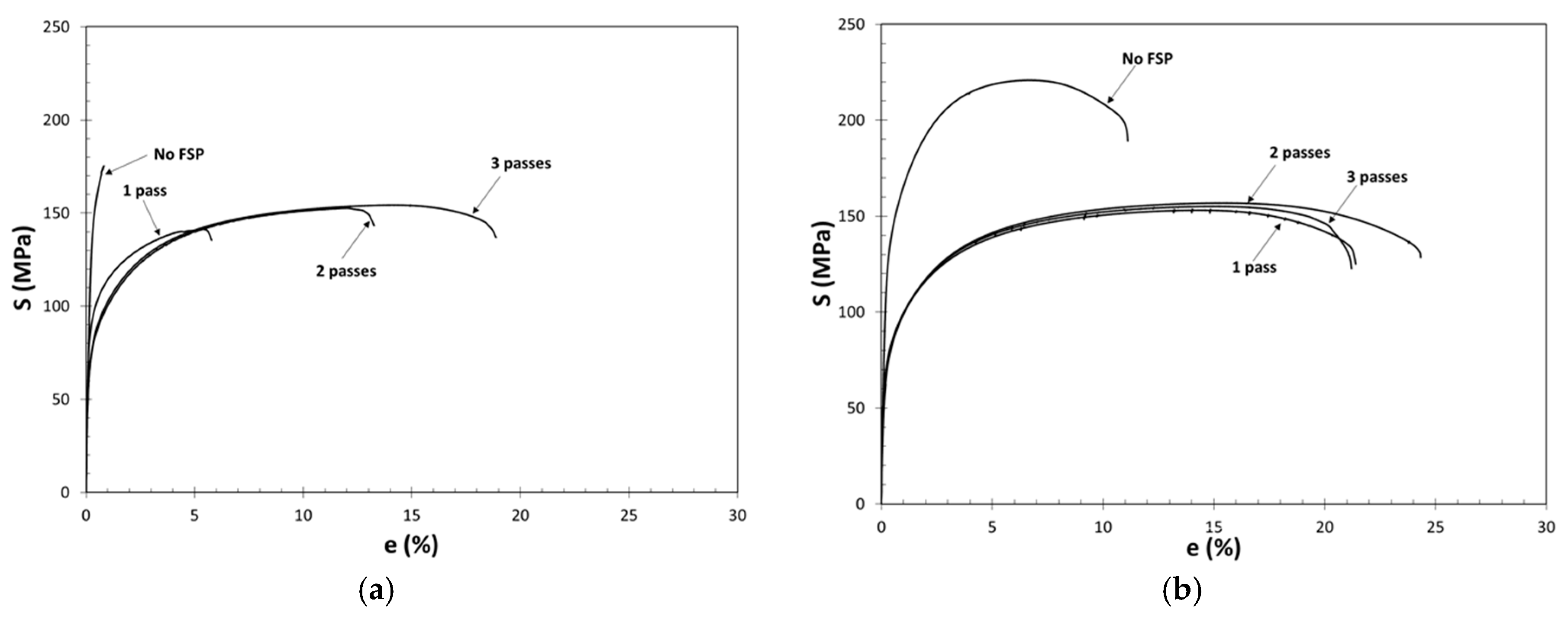
Specimens from commercial and continuously cast A356 ingots have been friction stir-processed, and tensile deformation has been characterized. These two types of ingots have been found to be damaged in the liquid state, but at different levels. In both cases, the microstructure has been refined and homogenized. FSP has been found to improve structural quality by breaking up bifilms. For the commercial ingot, each FSP pass has progressively improved structural quality, as evidenced by an 18 times increase in elongation (from 1.0 to 18.8% after three passes), whereas in the continuously cast ingot, it has taken only one pass for FSP to improve structural quality by doubling elongation (from 10.9 to 21.1%) after which additional passes have not resulted in further improvement. Analysis of tensile deformation behavior has shown that all FSPed specimens exhibit a distinct Stage III work hardening, as modeled by Kocks and Mecking. Through the analysis of tensile deformation behavior, it has been hypothesized that improvement in elongation and structural quality with FSP may not be solely attributed to the refinement of Si particles.

1. Introduction

Cast Al–Si–Mg alloys are usually used for high-strength components in aerospace and automotive industries [1]. One of the most commercially applied Al–Si–Mg alloys in industry is the A356 (Al–7%Si–0.4% Mg) alloy [2]. These alloys have a microstructure that consists of a primary aluminum matrix and an Al-Si eutectic. The eutectic Si particles have been observed [3] in situ to fracture early in tensile plastic deformation with intense slip bands appearing between fractured Si particles, which lead to cracks and eventually to final fracture. In situ mechanical testing of Si particles [4,5] has shown that while some particles reach the theoretical strength of 16 GPa [6,7,8], others have fractured at significantly lower stresses. This is consistent with other studies [9,10,11] in the literature, although the lowest fracture stress reported varies between studies. This reduction in strength can be attributed to defects inside the Si particles, such as pinhole defects [12], or even bifilms [13], on which they have been found [14,15] to nucleate heterogeneously. Bifilms are formed when the surface of the liquid metal is disturbed, causing the surface oxide film to fold over itself and achieve entrained into the bulk of the liquid metal. Bifilms have perfect atom-by-atom bonding between the surface oxide and the liquid metal underneath it, and have zero strength between the folded-over surfaces [16]. Therefore, they essentially form cracks [17] that cause premature failures in service [18,19]. Hence, some Si exhibit poor mechanical performance due to these artifacts from liquid metal damage during the casting process [6].
The fraction of cracked Si particles increases linearly with plastic deformation [3,20,21,22]. Moreover, the probability of a Si particle to crack at a given plastic strain is related to its equivalent diameter (deq) [23]. Hence, the statement by Zhang et al. [24] the ductility in cast Al-7%Si-Mg alloys is determined by the morphology and size of Si particles, and is widely accepted in the literature. As a result, much attention has been paid to reducing the size of Si particles in Al-Si alloys, such as chemical modification with Na or Sr [25,26,27,28], and even with other elements, such as Sm, Ag [29] and Sc [30].
An alternative to chemical modification is friction stir processing (FSP), a thermo-mechanical process developed to alter the microstructure of the alloy locally [31,32]. This is accomplished by plunging a rotational tool with a concentric and cylindrical pin into the metal [33,34,35] and pushing it forward at constant transverse and rotational speeds [36], causing the material around it to undergo severe plastic deformation and thereby producing a refined and homogenized microstructure [31,32,33,34,37]. Simultaneously, preexisting pores are completely healed [38,39]. In Al-Si alloys, FSP has been reported to refine the Si eutectic particles and grains [40]. The refinement of Si particles and elimination of pores during FSP have been suggested as the primary reason for the significant improvement in mechanical properties, such as tensile strength, elongation, and fatigue life [41,42,43,44,45,46].
FSP can be completed in one pass or, alternatively, in multiple passes. In each pass, the microstructure is modified due to severe plastic deformation. Although the change in microstructure after FSP with a single pass has been studied extensively, the effect of multiple passes on microstructural evolution in cast Al-Si alloys has received less attention. Recently, the authors [47] have characterized the effect of as-cast microstructure and the number of passes on the final shape, aspect ratio, and spatial distribution of Si particles in an A356 alloy. The authors have reported that when Si particles are coarse in the as-cast microstructure, they are progressively refined with each FSP pass. If Si particles are fine initially, FSP causes Si particles to coalesce with each pass, which has not been reported in the literature, to the authors’ knowledge. How (i) the initial Si particle sizes in the two starting materials and (ii) the uniquely different evolution of Si particles with each FSP pass affect tensile behavior has been characterized for the first time. Therefore, this study provides strong evidence on the underlying mechanisms for tensile ductility improvement in FSPed Al-Si alloys reported in the literature.

2. Experimental Details

Commercial quality (gravity die cast) and continuously cast (direct chill cast) ingots of A356 with nominal composition of 7 wt.%Si and 0.35 wt.%Mg (and up to 0.2 wt.% Fe) have been excised and machined into 100 mm long bars, with a gage width and depth of 4 mm. FSP was conducted on a vertical milling machine (Bridgeport, West Yorkshire, United Kingdom), with the FSP tool tilted 3° opposite to the processing direction. Single and multiple passes of 100 mm have been performed on a smooth working surface. Two and three FSP passes had 100% overlap over the previous zone. Subsequent fractography has validated the full overlap.
The FSP tool rotation rate (spindle speed) and transverse speed have been kept constant at 700 rpm in the clockwise direction and 50 mm/min, respectively. The tool has been made of H13 tool steel with a shoulder diameter of 18 mm. The cylindrical pin had a diameter of 5.9 mm, a length of 5 mm, and M6 threads. More experimental details are provided in a previous publication by the authors [47].
Tensile specimens were excised from the as-received ingots and FSPed materials, parallel to the FSP direction, at the CNC mini-mill (HAAS, Oxnard, CA, USA) following the ASTM-E8-M [48] standard for sub-size specimen, with the gage being completely within the stir zone. The specimens had a width of 5 mm, a depth of 3 mm, and a gauge length of 30 mm. The specimens were then mechanically polished to have a smooth surface. No additional treatment was given to the specimens. For each condition, one tensile specimen was prepared. Tensile tests were carried out on a Shimadzu tensile tester (Kyoto, Japan) with a strain rate of 10−3 s−1. An extensometer with a gauge length of 25 mm was attached to the specimen throughout the tensile tests.
Specimens for microstructural examinations were taken from the grips of the tensile specimens, cross-sectioned perpendicular to the FSP direction, and prepared by traditional polishing methods, with final polishing performed on a Buehler Vibromet II (Lake Bluff, IL, USA). A Tescan Mira 3 field emission scanning electron microscope (FE-SEM) (Brno, Czech Republic) equipped with an Oxford X-Max 50 energy dispersive spectrometer (Abingdon, UK) was used to evaluate microstructure on unetched specimens and the fracture surfaces of both cast and FSPed samples.

3. Results and Discussion

3.1. Microstructural Characterization of As-Cast Specimens

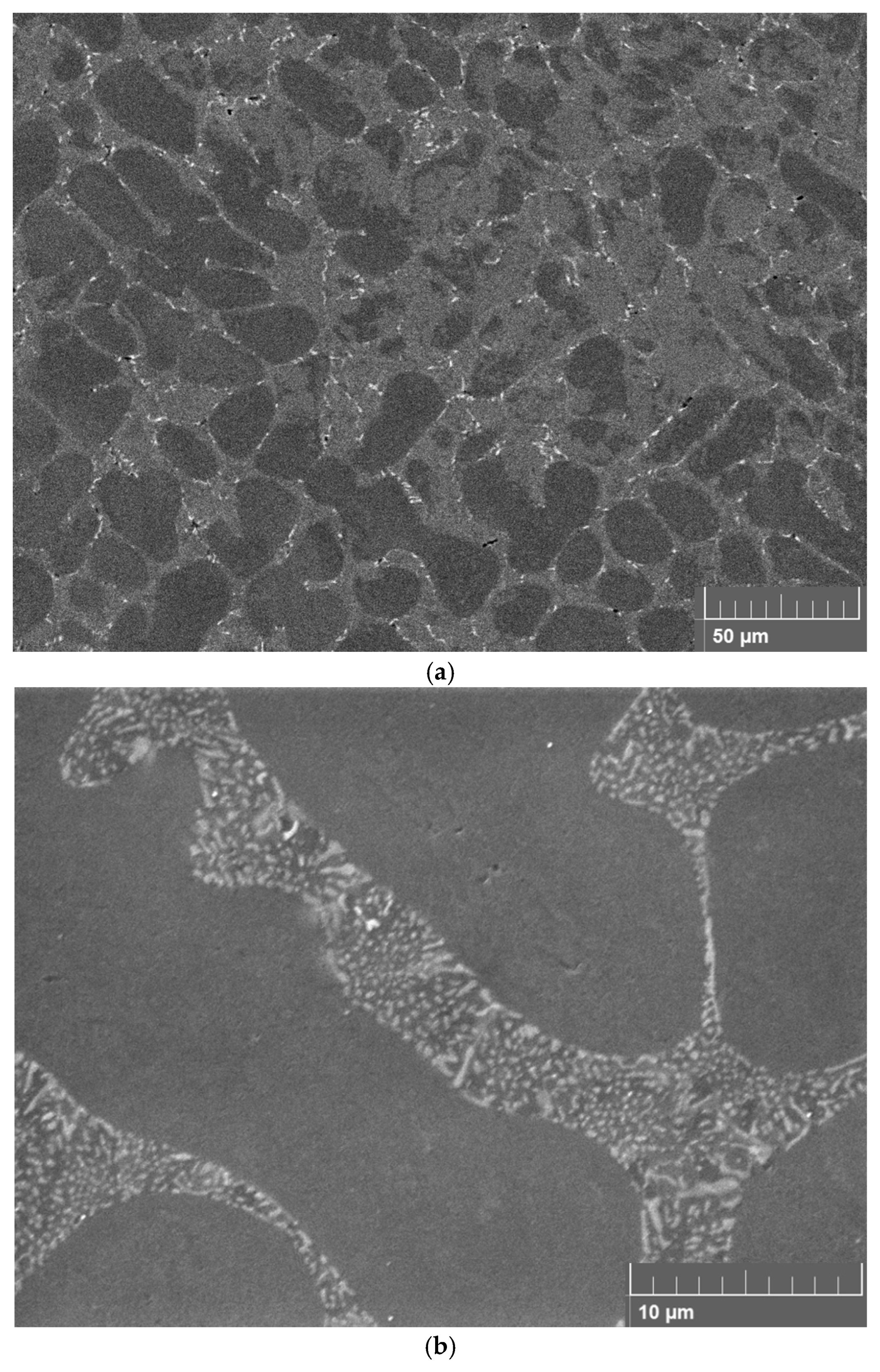
The microstructure of the commercial ingot in as-cast condition is presented in Figure 1. Figure 1a shows that the microstructure consists of large and elongated Si particles, with a secondary dendrite arm spacing (DAS) of 52 μm. In this alloy, Si is expected to form a lamellar eutectic structure. However, the Si particles of the commercial ingot of A356 are acicular and do not form typical lamellar eutectic colonies. Campbell [49] has referred to this type of Si particles as primary Si, which is expected to form in hypereutectic Al-Si alloys, and not in hypoeutectic alloys such as A356. Campbell has attributed these primary Si particles to the presence of bifilms, on which Si nucleates heterogeneously, as discussed above. Also shown in Figure 1a are Fe-bearing constituent particles, namely the β-platelets and Chinese script. The β-Al9Fe2Si2 phase has been designated as monoclinic [50] with many faults [51]. Cao and Campbell [52,53] have shown that β-platelets nucleate heterogeneously and grow on bifilms. The β-platelet indicated by an arrow near the northwest corner of Figure 1a, resembling an exclamation point, is noteworthy. The β-phase has encircled two pores with a link in between. This provides evidence that the surfaces of these pores are covered by an oxide film, i.e., a bifilm has been inflated during solidification by diffusion of hydrogen gas and/or under negative pressure developed during solidification. Simultaneously, the β-phase has nucleated on the same bifilm.
A Chinese script Fe-bearing particle is presented in Figure 1b. These particles have been found [54] in parts that solidify slowly, i.e., medium to large DAS as found for this specimen, and associated with Si particles. The particle shown in Figure 1b is indeed in contact with at least three Si particles. Although Chinese script particles have been designated as α-phase [55,56] with a stoichiometry of Al6Fe [57]. However, Ferdian et al. [54] have reported recently that Chinese script particles have the same stoichiometry and monoclinic structure as β-platelets. Shankar et al. [58,59] have reported that Si nucleates heterogeneously on Fe-bearing particles, especially the β-phase. Therefore, the Chinese script particle in Figure 1b most probably served as a nucleation site for the Si particles around it.
There is a distinct boundary within one of the Si particles in Figure 1b. A line scan has been conducted to determine whether there is a substance other than Si across this boundary. No other element has been detected. Hence, this boundary has been interpreted as a twin boundary.
Note that there are black dots on Si particles as well as the Chinese script particle, as indicated by arrows in Figure 1b. These are the Mg2Si phase that has nucleated heterogeneously on these particles. Mg2Si phase nucleating on Si particles has been reported [60] before. However, this is the first time that Mg2Si is observed to have nucleated heterogeneously on a Chinese script particle, to the authors’ knowledge.
The microstructure of the continuous cast ingot is presented in Figure 2. Secondary dendrite arm spacing is 14 μm, which is much smaller than that of the commercial ingot. Hence, based on either the Feurer/Wunderlin (as explained by Kurz and Fisher [61]) or Kirkwood [62] models linking SDAS to solidification times, it is estimated that the continuously cast ingot solidified at a rate that is approximately 50 times faster than that of the commercial ingot. The Fe-bearing constituents are all β-platelets; no Chinese script constituents have been found. Moreover, the sizes of β-platelets are smaller, which is in agreement with the findings of Samuel et al. [56,63] and Vorren et al. [64] who reported that the size of β-platelets increases with increasing DAS, i.e., solidification time. The Si particles visible in Figure 2b are much smaller than those in the commercial ingot. They form the lamellar eutectic structure expected in this alloy.
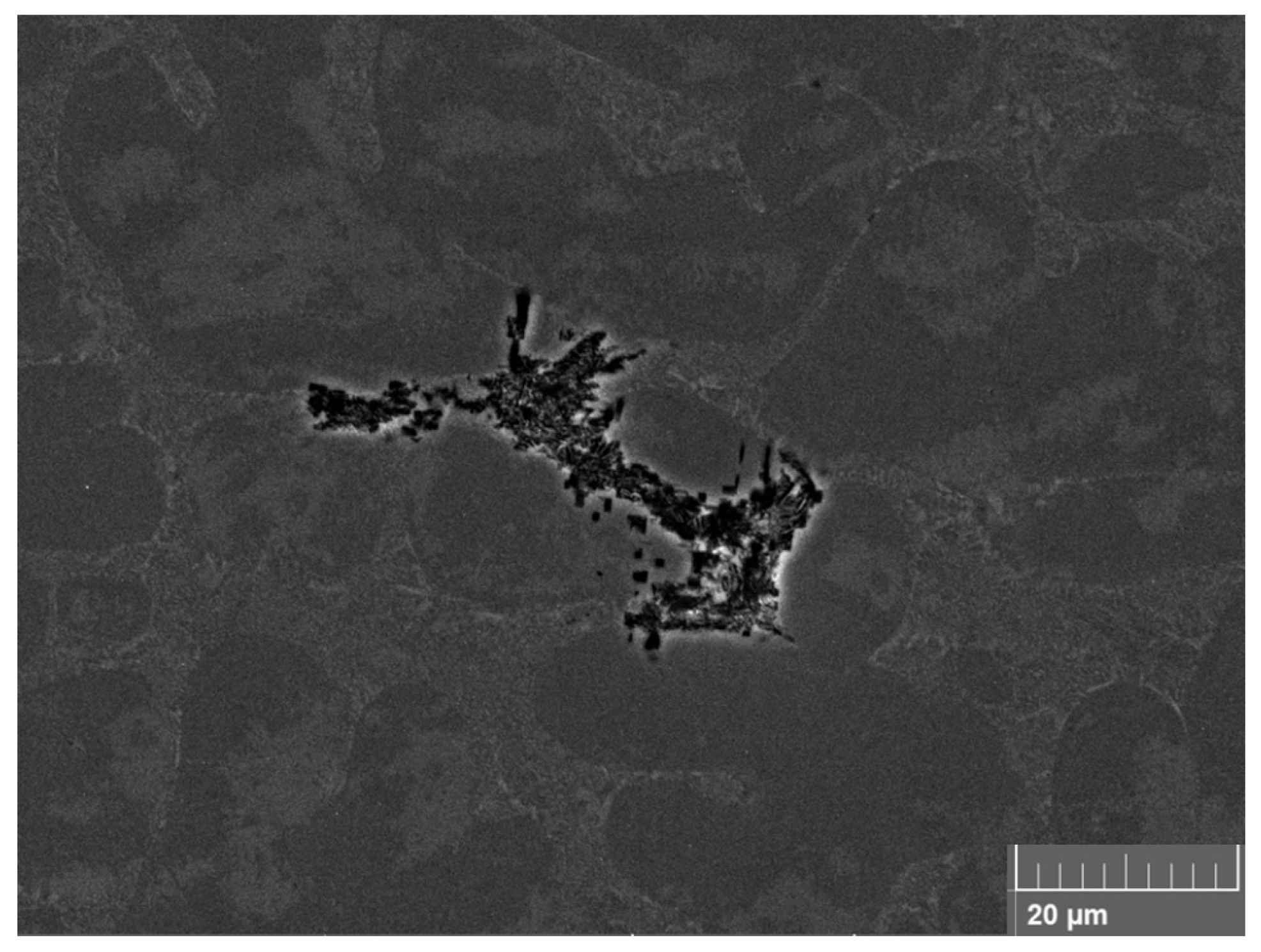
A coarse oxide film found during metallographic examination of the commercially cast alloy is presented in Figure 3. The film has been interpreted as an “old” MgO-Al2O3 mixed spinel film [65], which previously occupied the surface of the melt. After growing at the surface, it has been entrained into the bulk liquid during pouring. This film is a good example of the damage that can be caused to the liquid metal by pouring.

3.2. Microstructural Characterization of FSPed Specimens

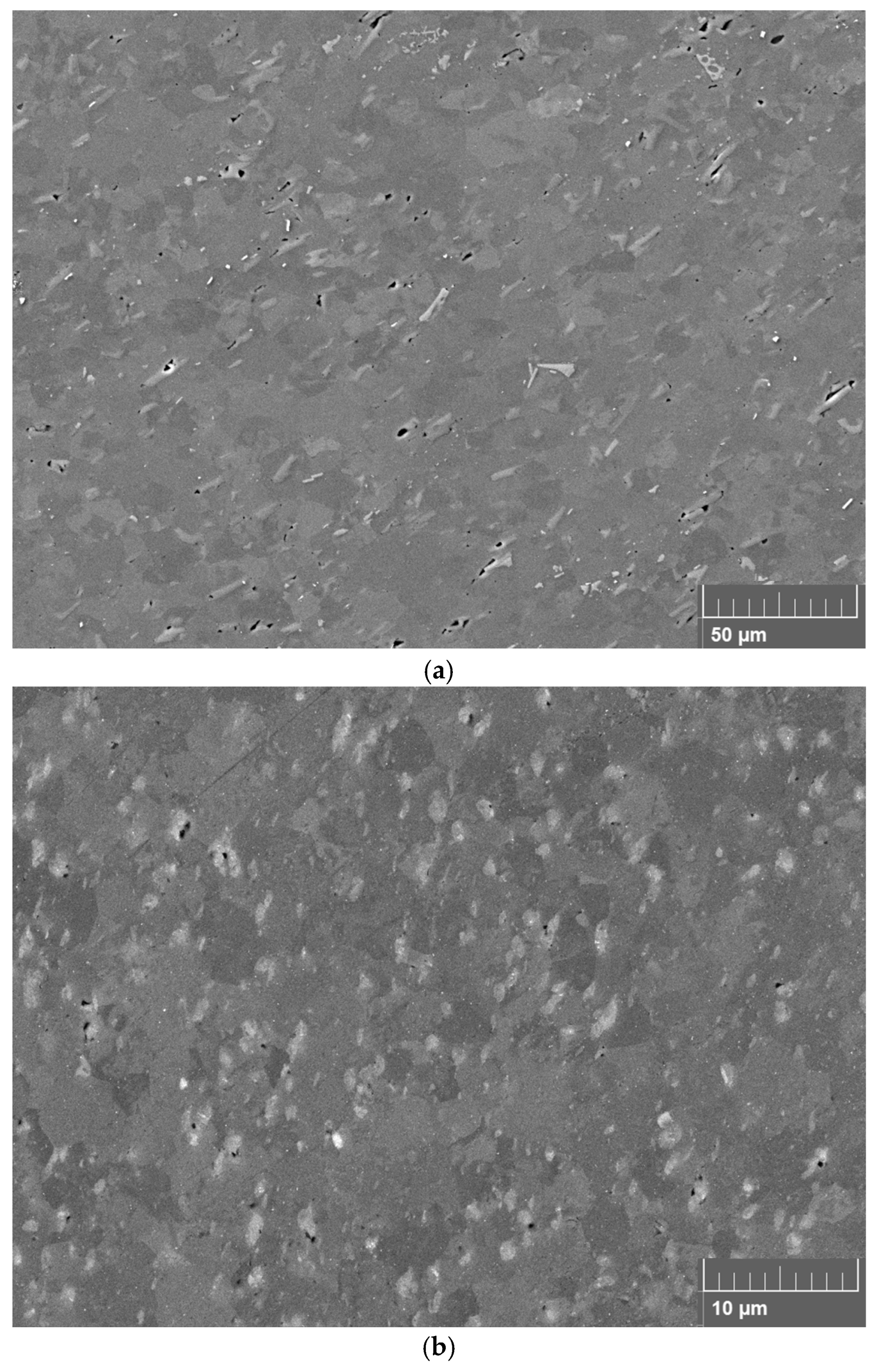
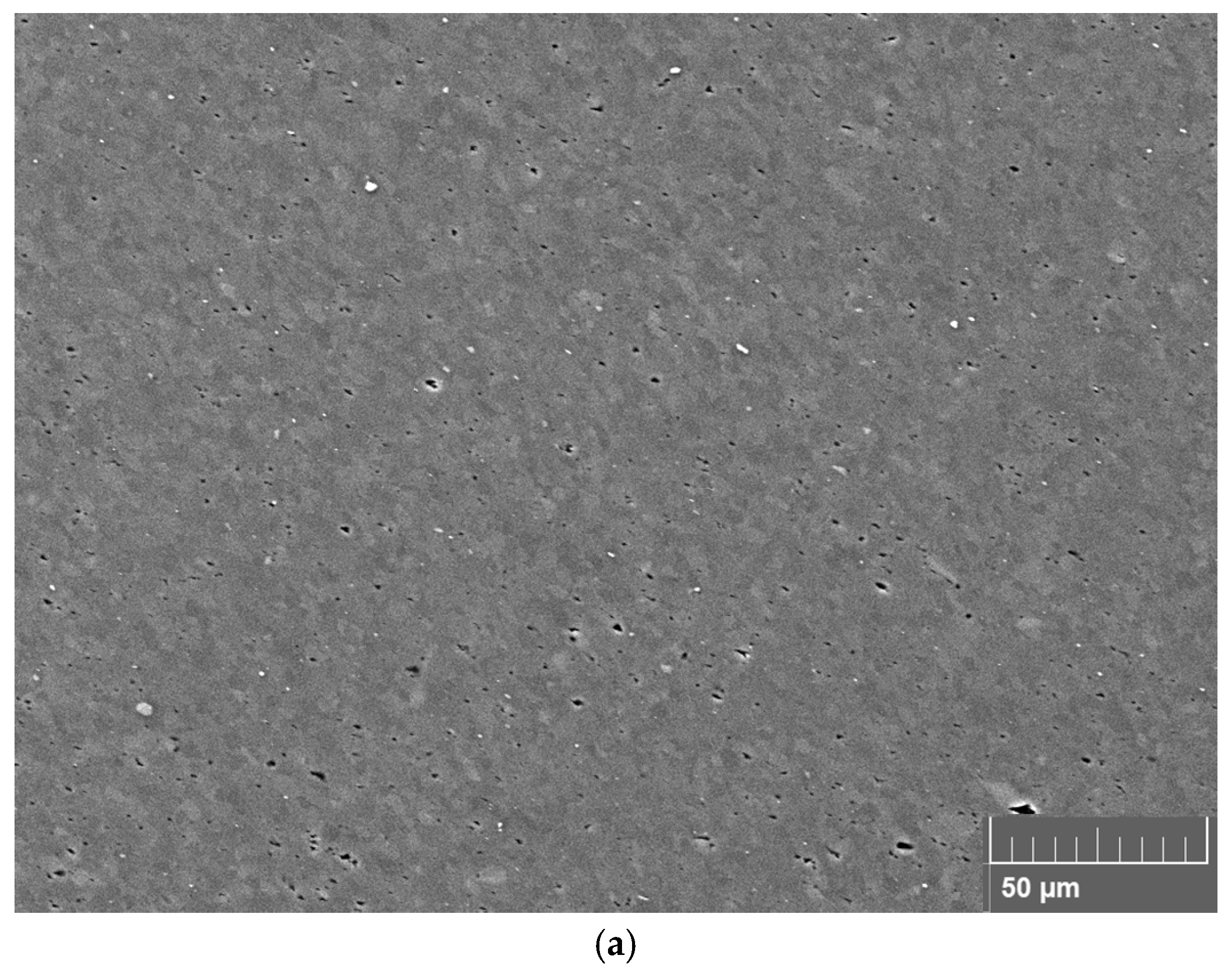
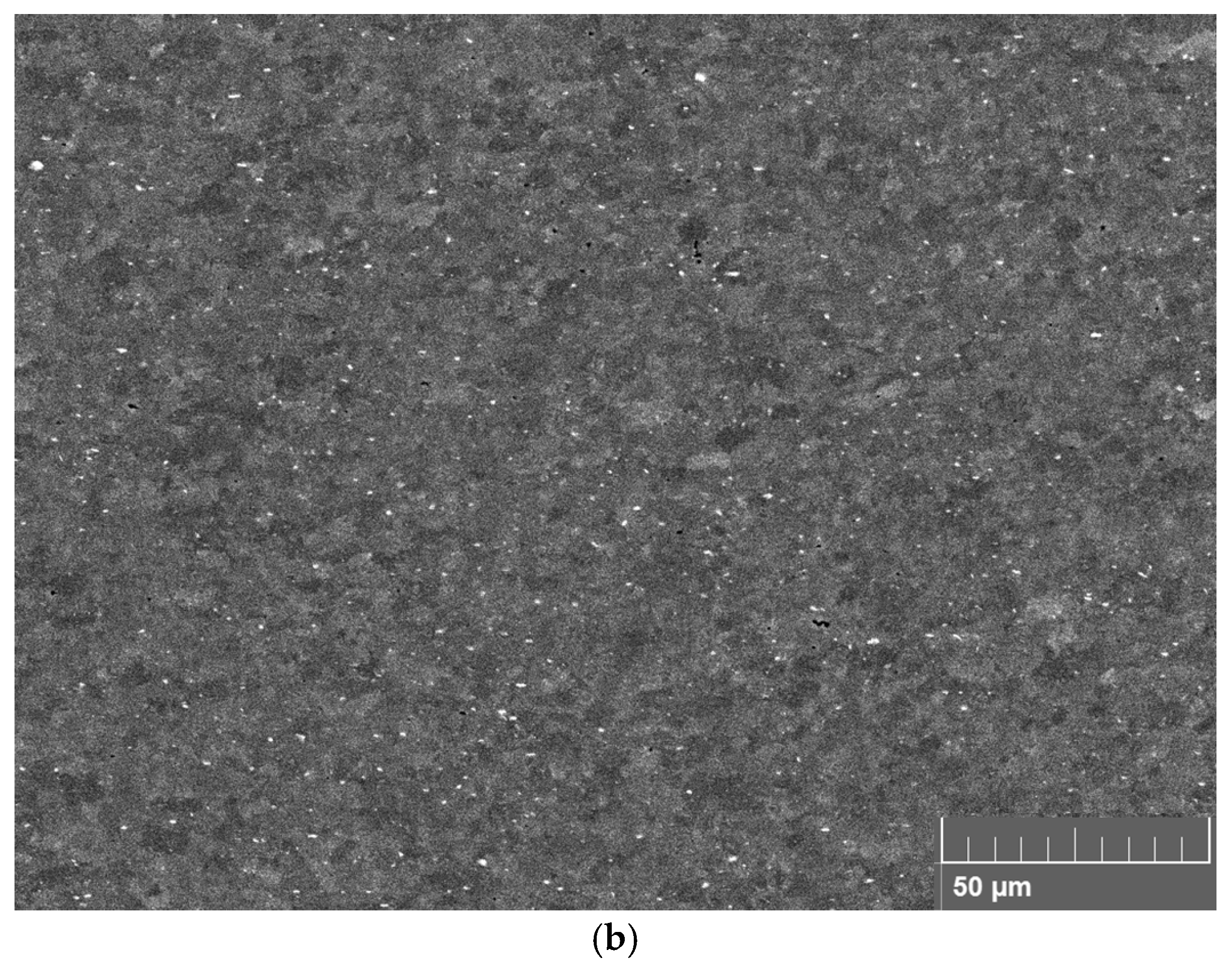
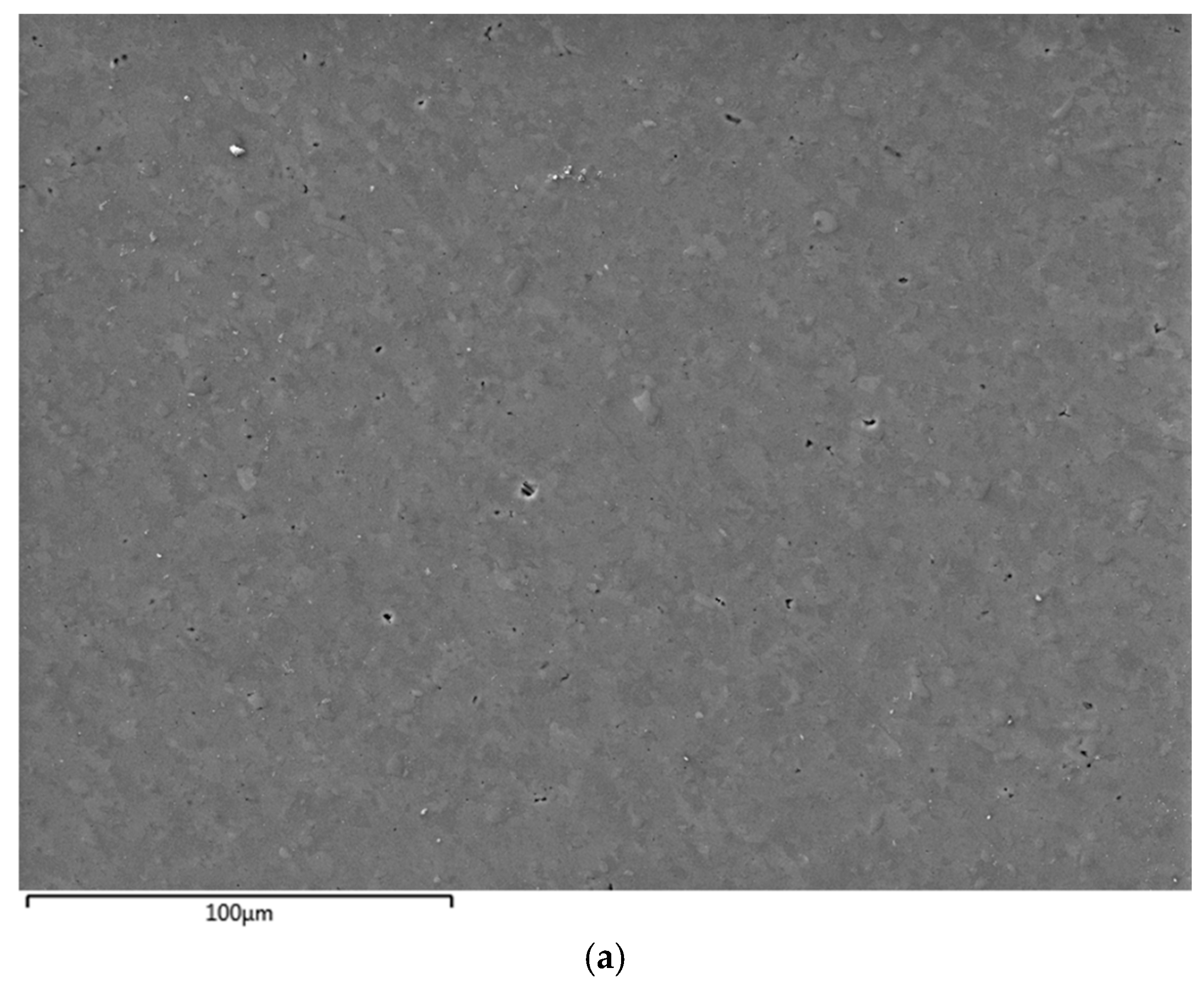
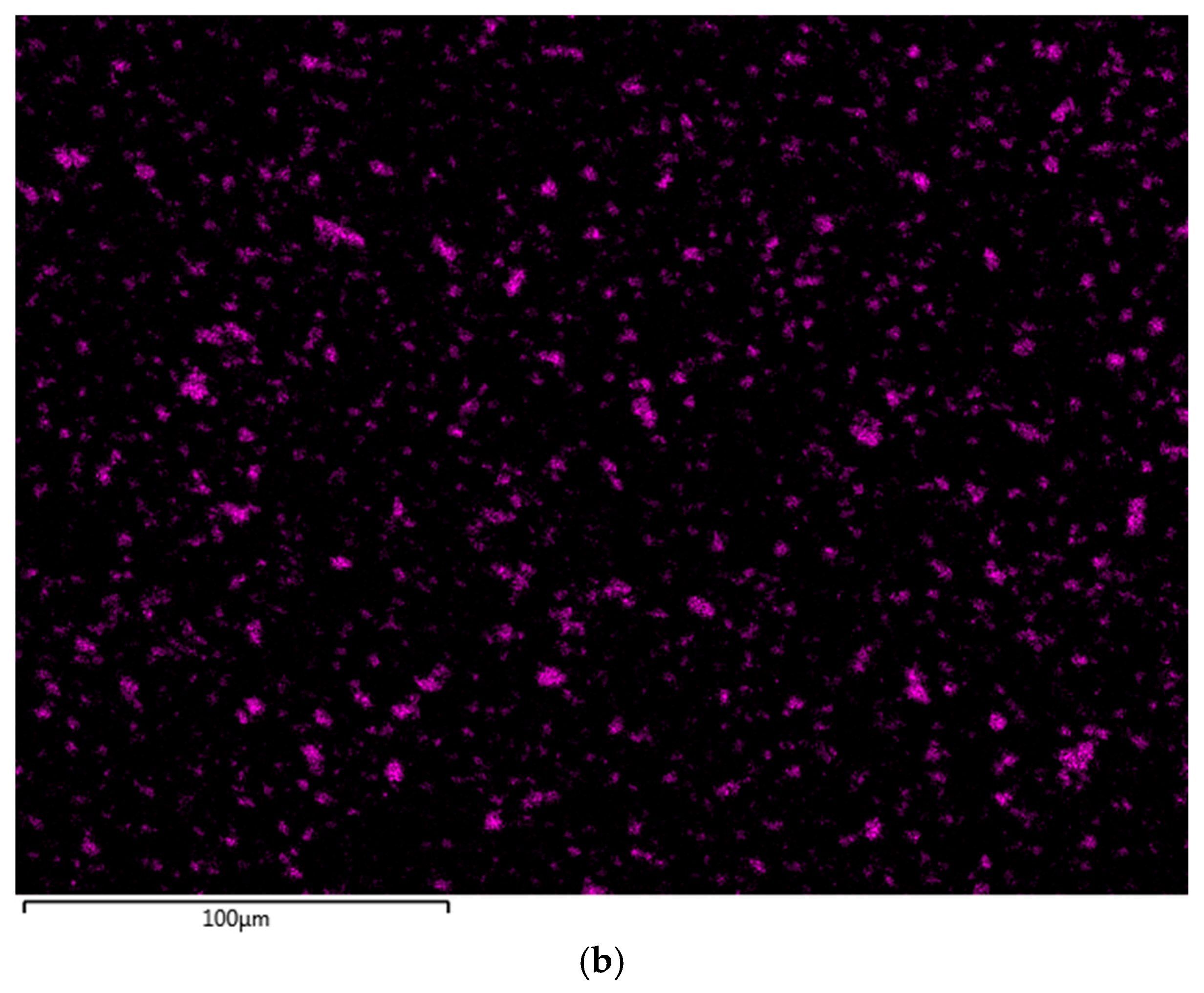
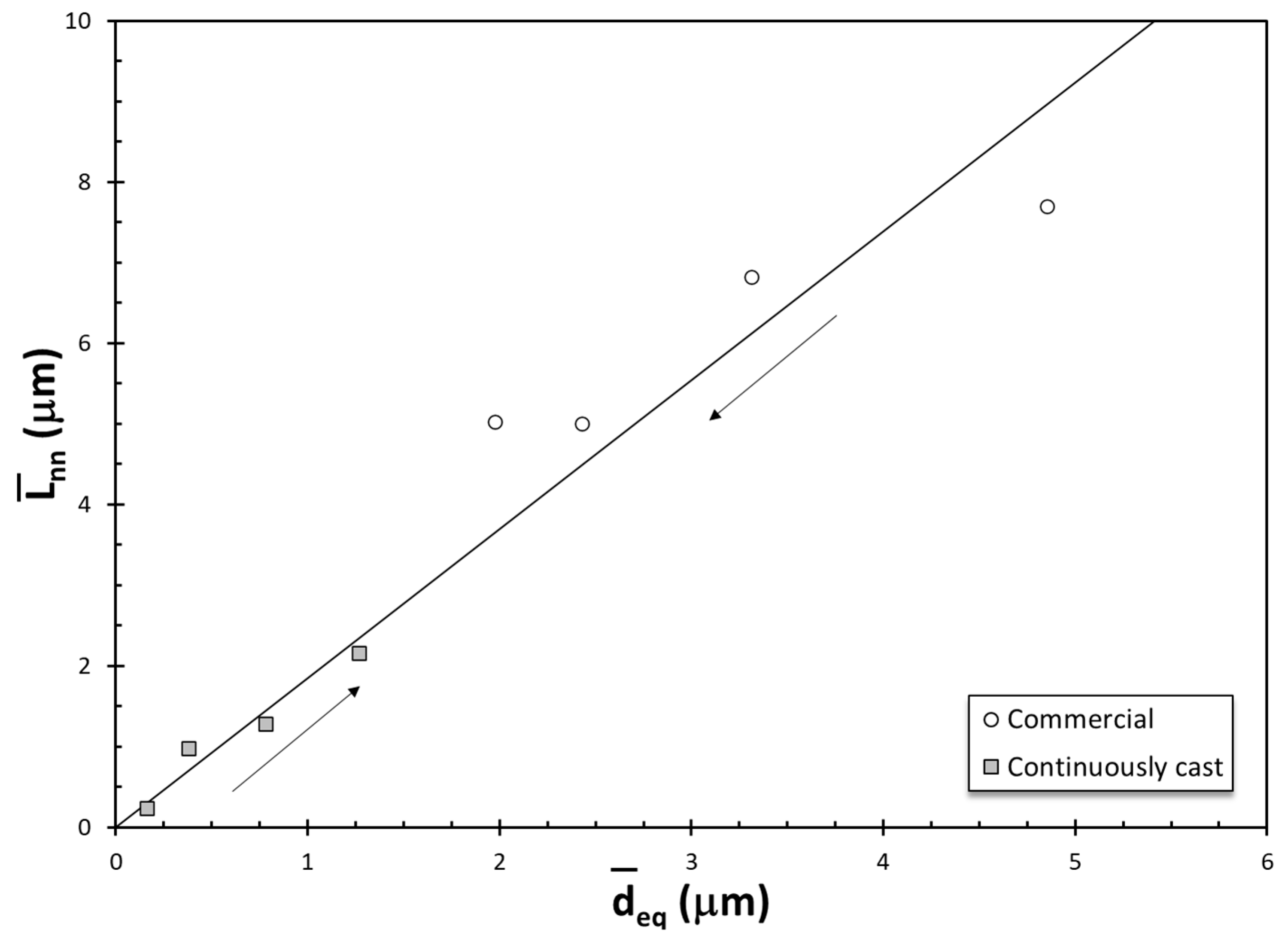
The microstructural evolution after one FSP pass for both ingots is presented in Figure 4. In the commercial ingot, Figure 4a, one FSP pass has broken the acicular Si particles, but some particles as large as approximately 20 μm have survived. In the continuously cast ingot, Si particles are not visible in the secondary electron mode, Figure 4b. The microstructure obtained after three FSP passes is presented in Figure 5. Note that in both specimens, the microstructure is quite refined and is almost indistinguishable from each other. Hence, FSP has produced almost the same microstructure after three passes despite the vast difference in the starting as-cast microstructure. Note that no Si particles are visible in Figure 5 either. That is why the authors, in an earlier publication [47] dedicated solely to the microstructural evolution in these two starting materials, with each FSP pass, have analyzed Si X-ray maps and digital image processing to acquire size and nearest neighbor distance data in these FSPed specimens. Such a micrograph and the associated Si X-ray map are presented in Figure 6, showing the distribution of fractured Si particles in the aluminum matrix after two FSP passes in the commercial ingot. The reader is invited to refer to the earlier publication [47] by the authors for a detailed analysis of microstructural changes. Average equivalent diameters ( d ¯ e q ) and average nearest neighbor distances ( L ¯ n n ) for the same as-cast and FSPed specimens, as reported previously by the authors [47], is summarized in Table 1. It should be noted that the average sizes and nearest neighbor distances are results of statistical analyses, which include fitting lognormal distributions to both datasets. Additional statistical information can be found in the previous paper by the authors [47]. In commercial ingot specimens, Si size and nearest neighbor distance have been reduced with each FSP pass. Conversely, each FSP pass has resulted in coalescing of Si particles and an increase in the nearest neighbor distance in the continuously cast ingot specimens. Curious reader is referred to the original study [47] for more details. X-ray maps have also shown that no Fe-bearing particles have survived FSP in all samples.
The cross-plot of average Si diameter and average nearest neighbor distance values in Table 1 is provided in Figure 7. The relationship is linear, as would be expected, based on established stereology concepts by DeHoff [66] and Bansal and Ardell [67]. It is significant that the two as-cast microstructures approach each other with each FSP pass, as indicated by arrows that point in the direction of progression with each FSP pass. To the authors’ knowledge, this effect of FSP has not been reported before in the literature. Hence, it is conceivable that there may be a limiting microstructure that can be reached with more FSP passes. Once reached, additional FSP passes would not result in further microstructural evolution. More research is needed to test this hypothesis.

3.3. Characterization of Tensile Deformation

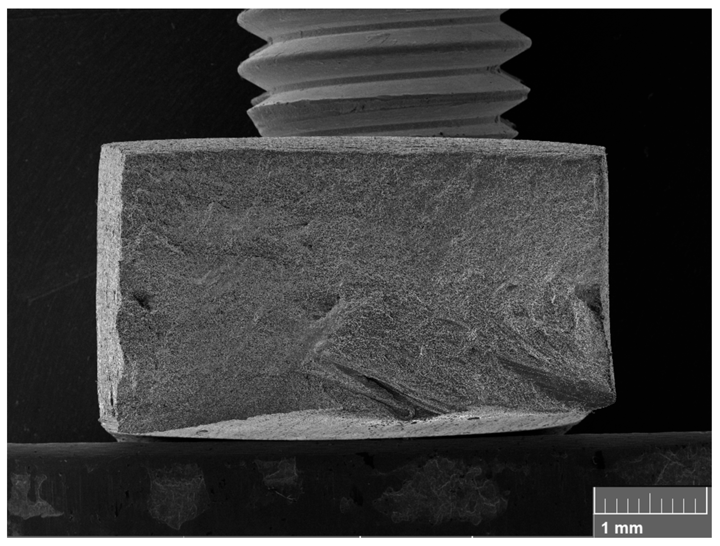
The engineering stress (S)-strain (e) curves for each specimen condition are presented in Figure 8. Note that the commercial ingot specimen with no FSP has fractured early in the elasto-plastic region. With each FSP pass, ductility is enhanced, Figure 8a. After 3 passes, the appearance of an ultimate tensile strength, i.e., necking and nonuniform elongation, is visible. In contrast, in the continuously cast ingot specimens, a clear ultimate tensile strength is visible in all conditions, especially in the specimen with no FSP, Figure 8b. Nonuniform deformation past necking has been reported [68] in Al alloys with 10 to 20 wt.% Si produced by sintering, and A357 (Al–7 wt.%Si–0.6 wt.%Mg) alloy castings [69]. Therefore, necking and subsequent nonuniform deformation in Al-Si alloys should not be unexpected. The overall fracture surface of the commercial ingot specimen after three passes is presented in Figure 9, showing the reduction in area around where the fracture has taken place.
The tensile properties of all specimens are listed in Table 2, which shows yield strength (σy), tensile strength (ST), and elongation (eF). Note in Table 2 that there is a significant drop in yield strength with FSP for both ingots.
For the commercial ingot, the as-cast condition has exhibited 1.0% elongation, much lower than 10.9% by the continuously cast ingot. This difference can be attributed to the differences in the level of entrainment damage [14,70,71] given to the liquid metal. The level of damage in these two ingots has been examined by Erzi and Tiryakioğlu [72], who have remelted specimens from these ingots without causing any new bifilms. Subsequently, they have characterized the visible damage, i.e., pores [73], after allowing them to solidify in a reduced-pressure environment. Micro-computer tomography (μ-CT) scans have shown that (i) both ingots have sustained liquid metal damage, (ii) commercial ingot is damaged more, as evidenced by its (i) pore fraction that is four times higher than that of the continuously cast ingot, and (ii) number density of pores that is almost 2.5 times that in continuously cast ingot.
Turning attention back to Table 2, after the first FSP pass, the reduction in yield strength is accompanied by an increase in elongation for both ingots. Since FSP has been shown [74] to break entrained oxide films, this improvement in ductility after the first pass can be attributed not only to the decrease in yield strength but also to the breaking of bifilms. Since Si has been reported to nucleate and grow on bifilms [13,14,15], the reduction in Si size with each FSP pass in the commercial ingot can be interpreted as a simultaneous reduction in bifilm size, resulting in further improvement in ductility with each pass. In the continuously cast specimens, elongation remains almost the same after the first pass. Hence, bifilms seem to have been eliminated after the first pass.

3.4. Structural Quality Assessment

Because of the different levels of yield strength, elongation has been normalized by using the structural quality index, QT [75] such that
Q T = e F β 0 β 1 σ Y
where β0 = 36.0% and β1 = 0.064 (%/MPa) for cast Al-Si-Mg-(Cu) alloys. The denominator of Equation (1) represents the ductility potential of the alloy family. The values of QT of the eight specimens are listed in Table 2. It is noteworthy that only after two FSP passes, the commercial ingot specimen has reached a similar structural quality level as the continuously cast specimen with no FSP, demonstrating the importance of the level of liquid metal damage in ingots and how the need for additional processing can be eliminated by selecting ingots with the least level of entrainment defects. Note that a QT value of 1.0 has not been approached in any FSPed condition, suggesting that the full potential of FSP has not been attained in the present work.

3.5. Fracture Surfaces

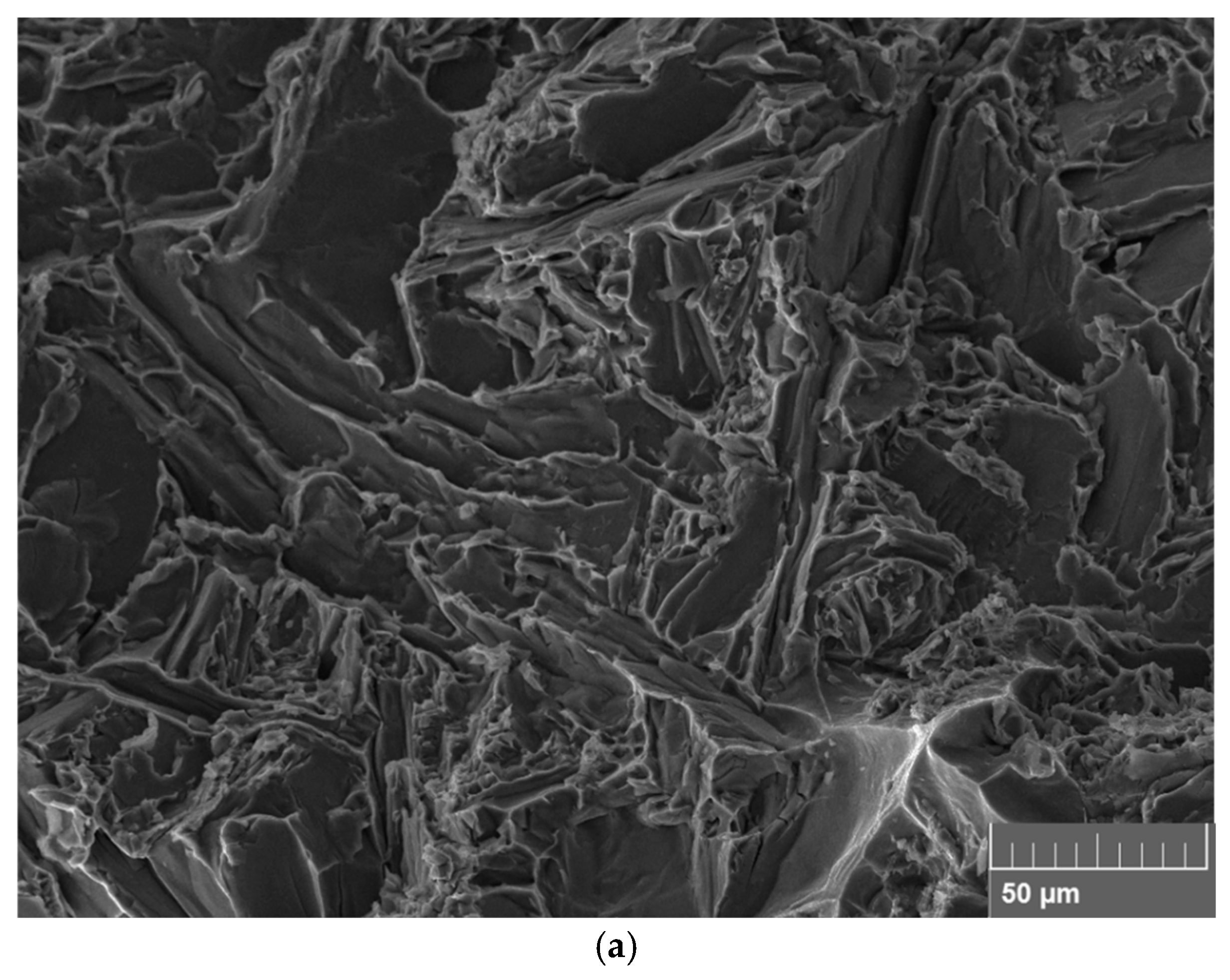
Fracture surfaces in as-cast conditions for both ingots are presented in Figure 10. For the commercial ingot, Figure 10a, the fracture surface has large areas of cleavage fracture. Moreover, no dimples have been identified on the fracture surface. Both are indicative of the presence of a high density of bifilms, which have resulted in low elongation. For the continuously cast ingot, no traces of cleavage fracture are observed, and the fracture surface shows areas of dimples as well as fracture through the Si eutectic, Figure 10b. The progress of fracture through the eutectic zones is an indication of low density of bifilms [76].
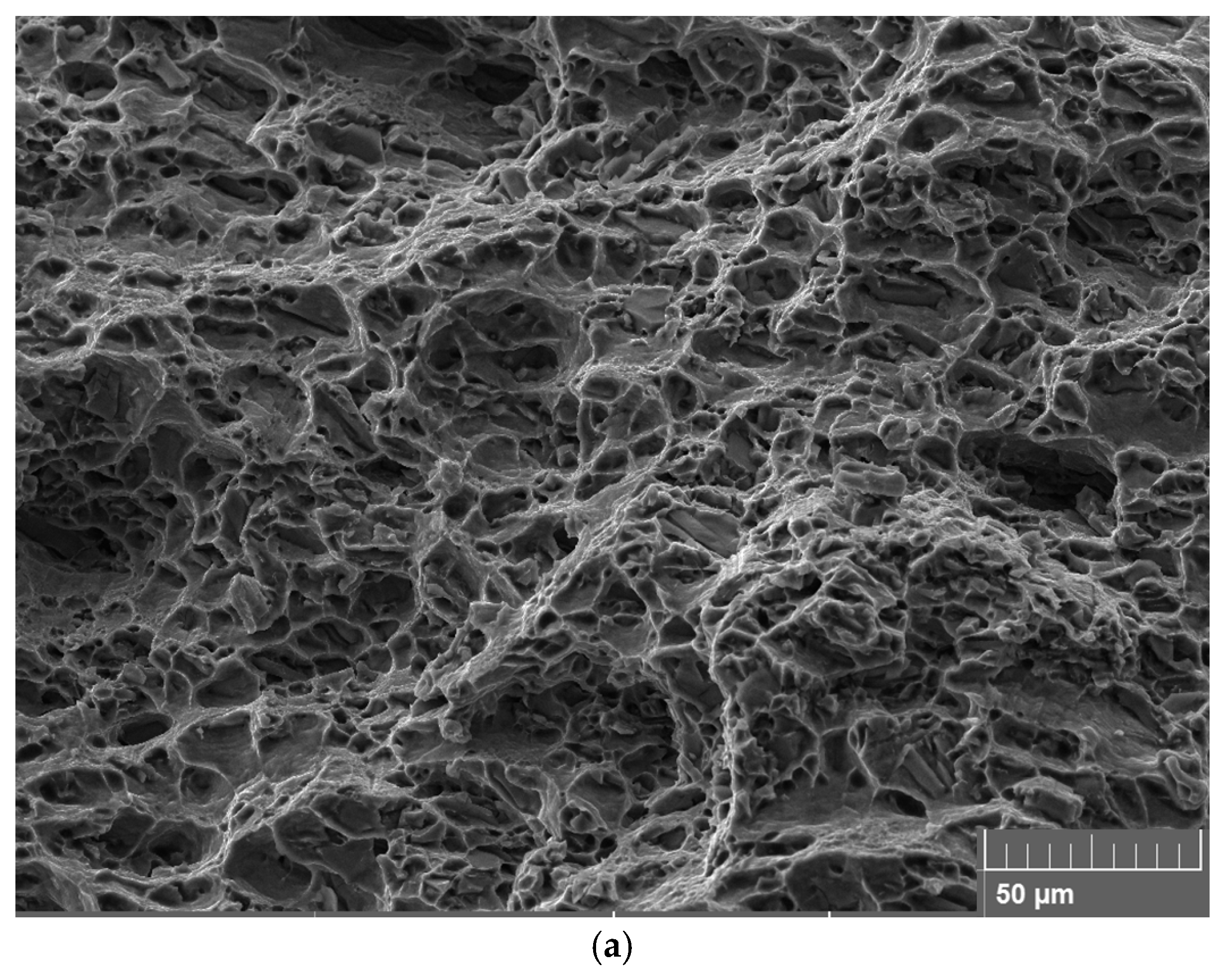
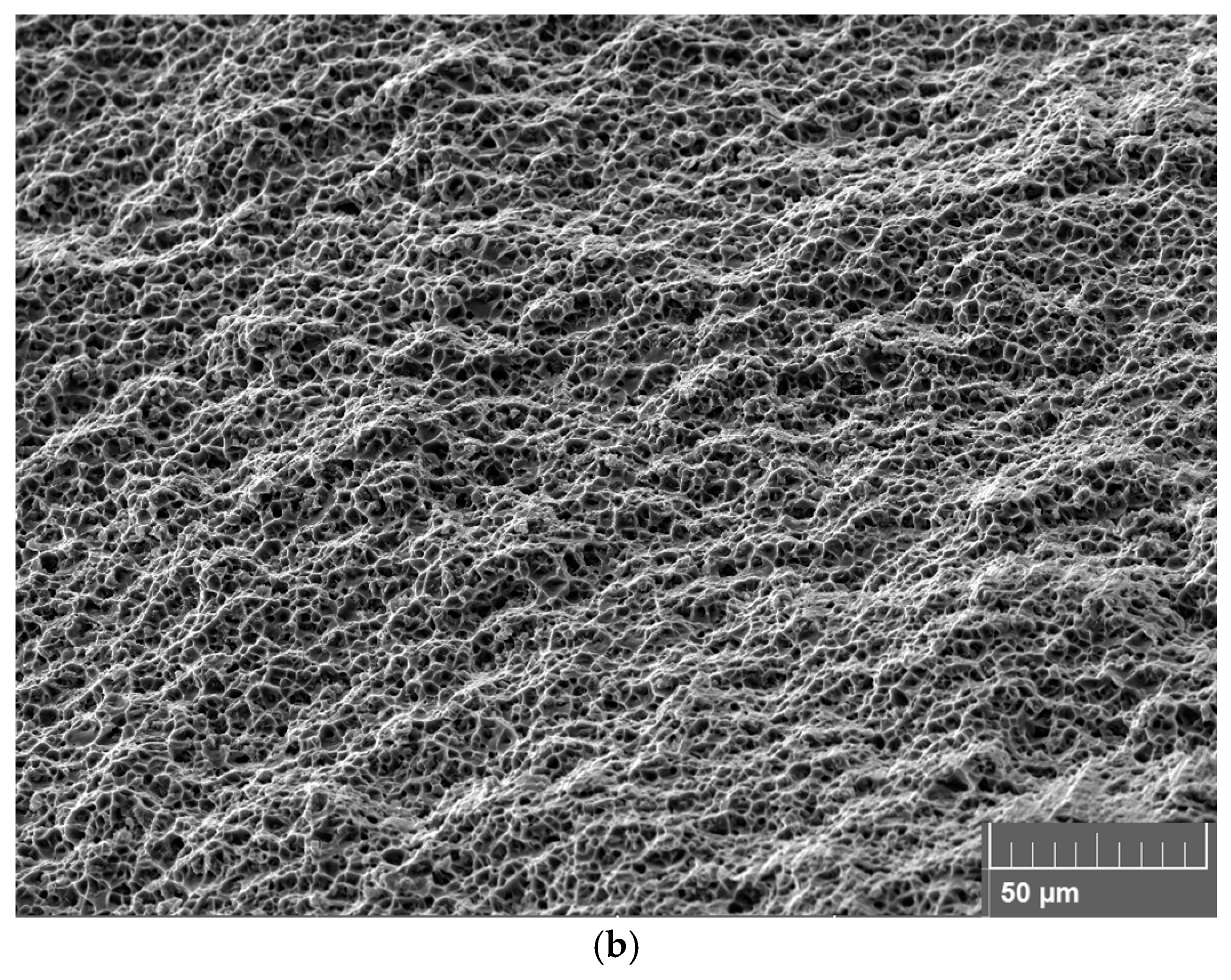
After one FSP pass, Figure 11a, the fracture surface of the commercial ingot is changed from mostly cleavage to large dimples on the fracture surface. In the continuously cast specimen, Figure 11b, the fracture surface is covered by finer dimples and no sign of cleavage. For two and three passes, similar fracture surfaces have been observed with dimples achieving finer after each pass, especially for the commercial ingot specimens, which is in agreement with the results of Meenia et al. [77].

3.6. Characterization of Work Hardening Behavior

It is well known that metals with a face-centered cubic unit cell follow the Kocks–Mecking (KM) Stage III work hardening model [78,79,80], which is described by:
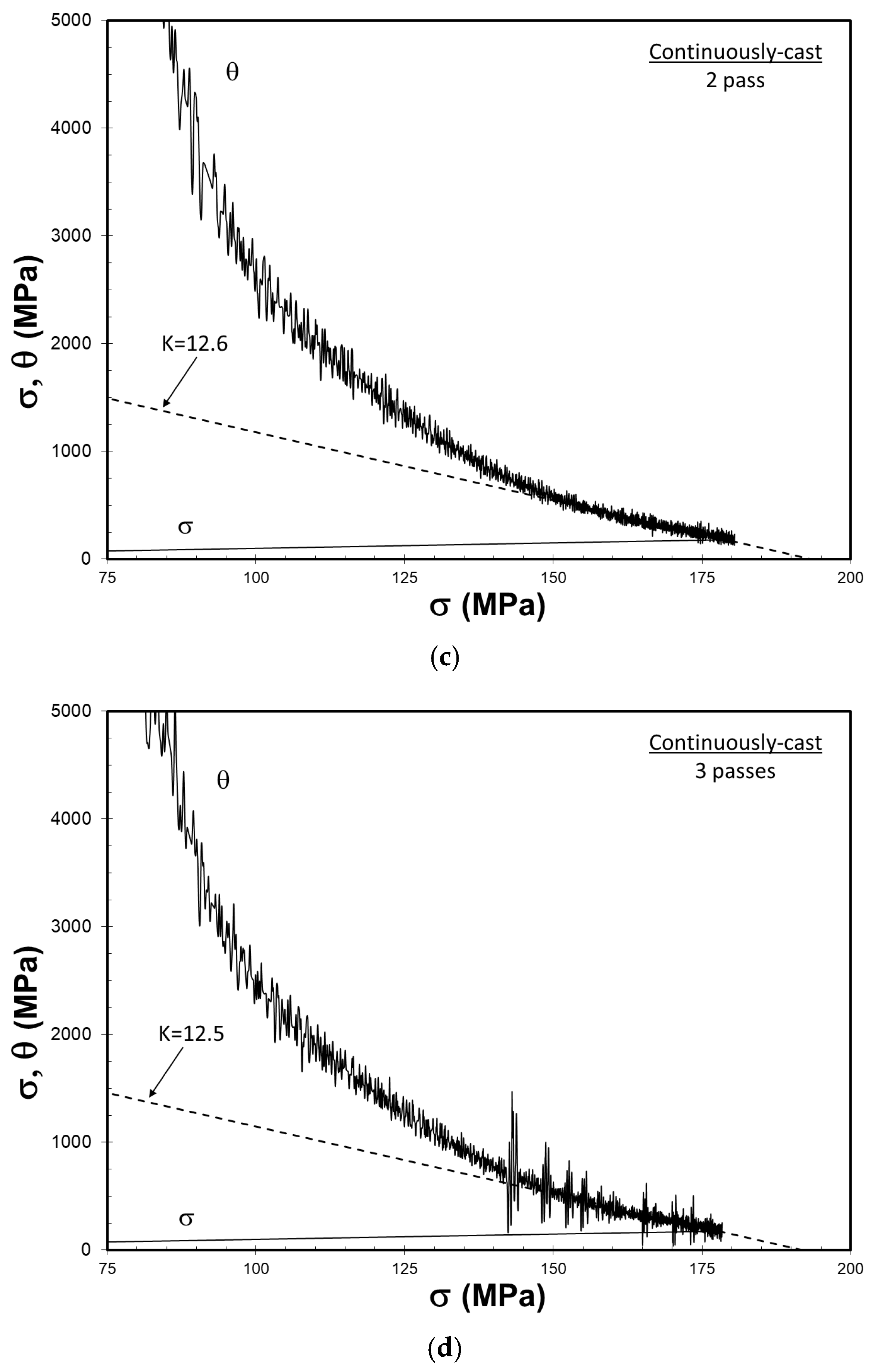
θ   = d σ d ε p = θ 0 K σ
where θ is the instantaneous work hardening rate (MPa), σ is true stress (MPa), εp is true plastic strain, θ0 is the initial work hardening rate (MPa), and K is a unitless parameter that is mainly dependent on Stage II work hardening rate and strain rate. Stage III starts when the work hardening rate drops to 2 to 3 GPa. This is the stage where most of the elastoplastic deformation has been found [81] to take place.
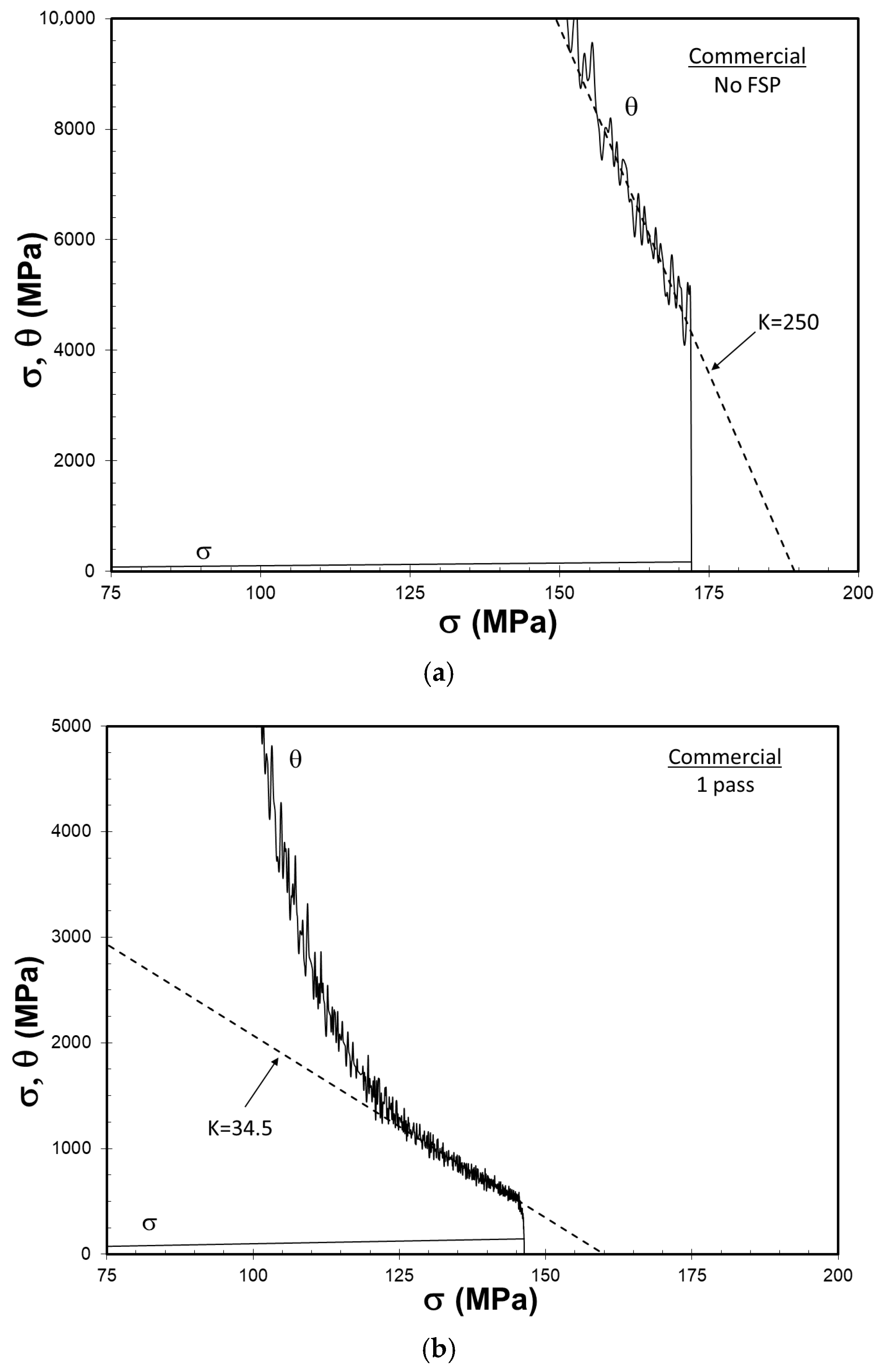
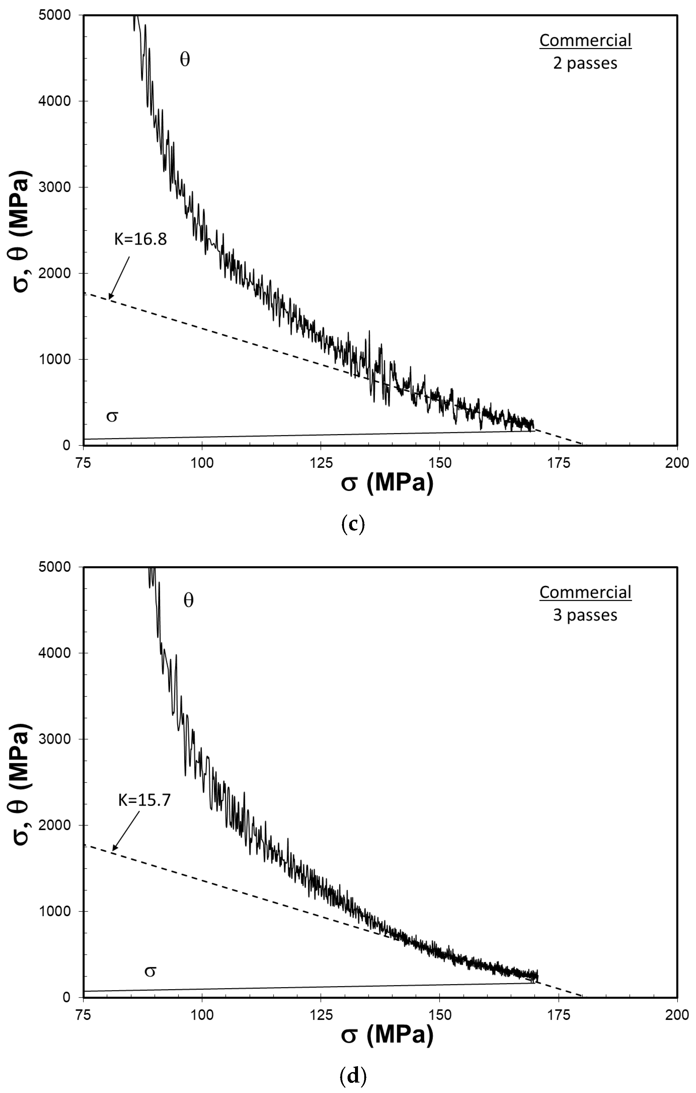
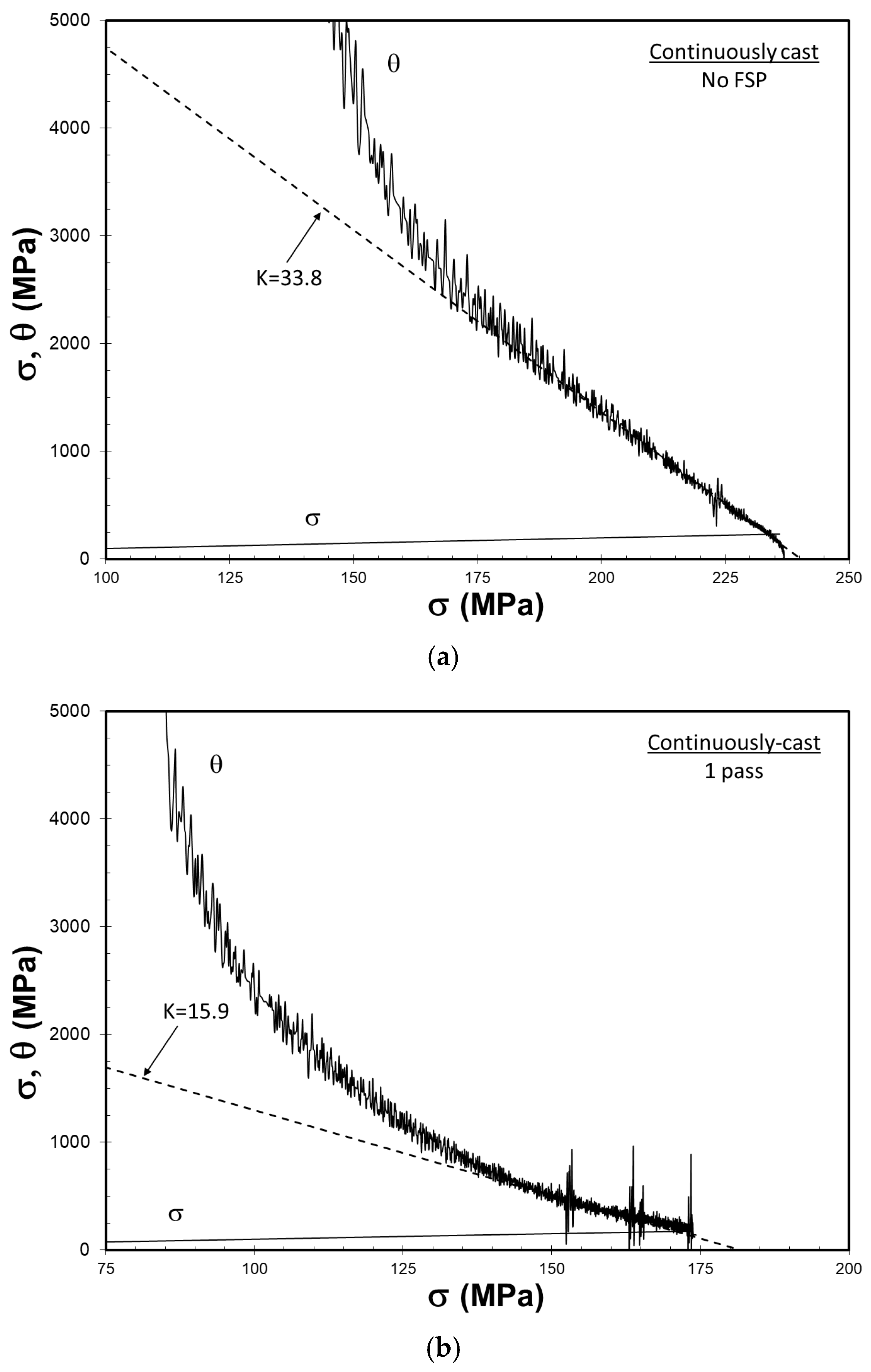
The Kocks–Mecking analysis of tensile data from commercial and continuously cast specimens is presented in Figure 12 and Figure 13, respectively. Note that for each specimen, the instantaneous work hardening rate is plotted versus true stress to determine whether the Considere criterion has been met in each case. In all specimens, except for the as-cast condition for the commercial ingot, there is a distinct Stage III work hardening, where θ changes linearly with σ, has been reached. The results of Kocks–Mecking analysis are summarized in Table 3.
Turning attention to Figure 12a, the linear decrease in θ with σ takes place at work hardening rates above 3 GPa. Tiryakioğlu and Alexopoulos [82] have shown that Stage II in A357 alloy specimens also follows a linear trend. Note that there is a sudden drop in θ immediately before the final fracture. This drop has been attributed [76,83,84] to pores and bifilms, both of which stem from the liquid metal damage. The extensive damage given to the commercial ingot is also evidenced by low elongation and QT. With one FSP pass, Figure 12b, Stage II is completed and followed by a distinct Stage III work hardening, indicating the significant improvement in the structural integrity of the specimen with FSP. However, there is again a sudden drop in θ immediately before fracture, indicating that not all bifilms have been eliminated, as discussed before. With the second and third passes, Figure 12c,d, the curves for θ and σ intersect without a sudden drop preceding the final fracture. Note that the value of K has decreased progressively with each FSP pass. For the continuously cast ingot, the Considere criterion has been met in all specimens without a sudden drop in θ, Figure 13, including the as-cast specimen. After each of the first two FSP passes, the value of K has decreased, after which it has remained essentially unchanged.
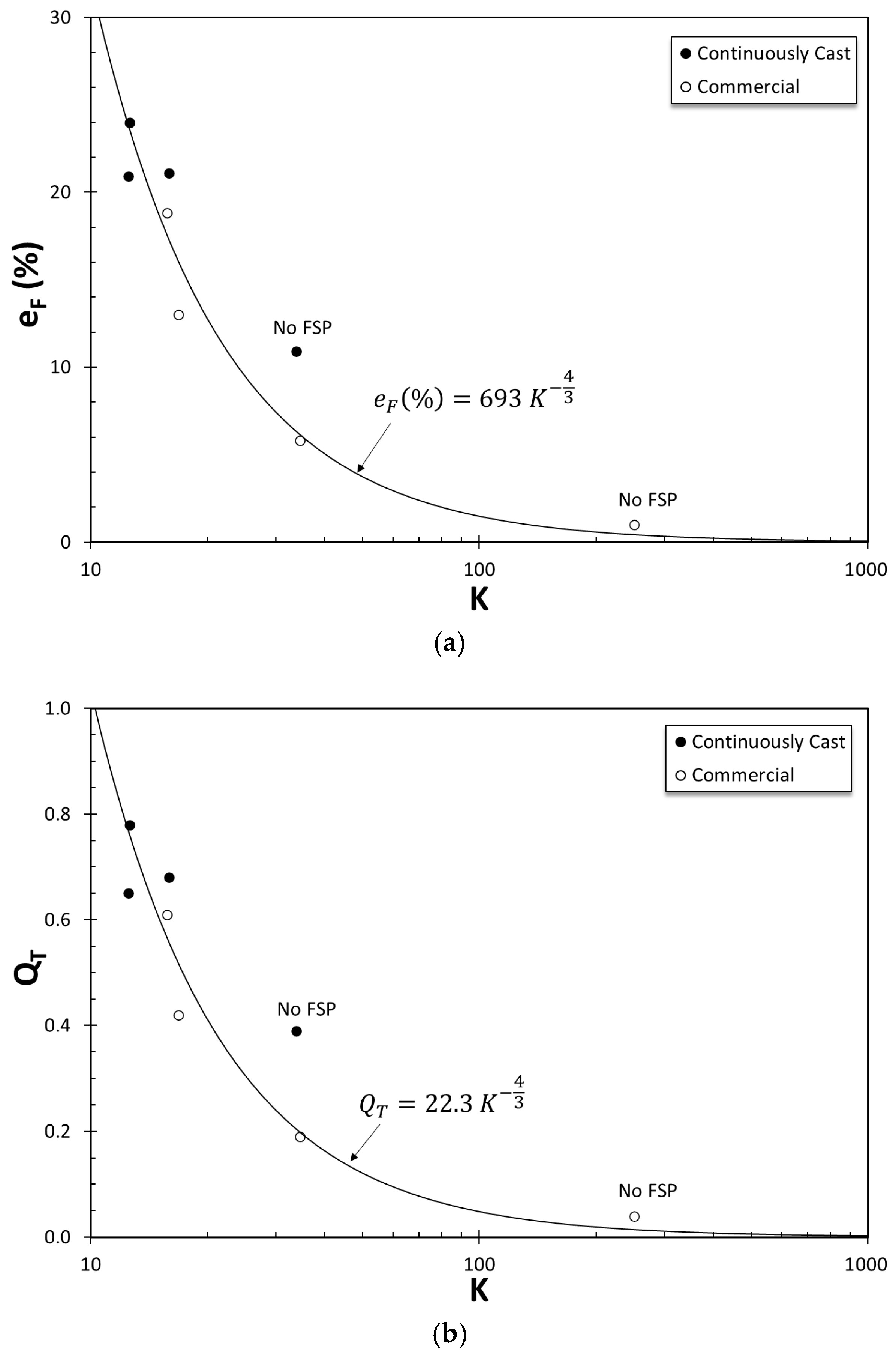
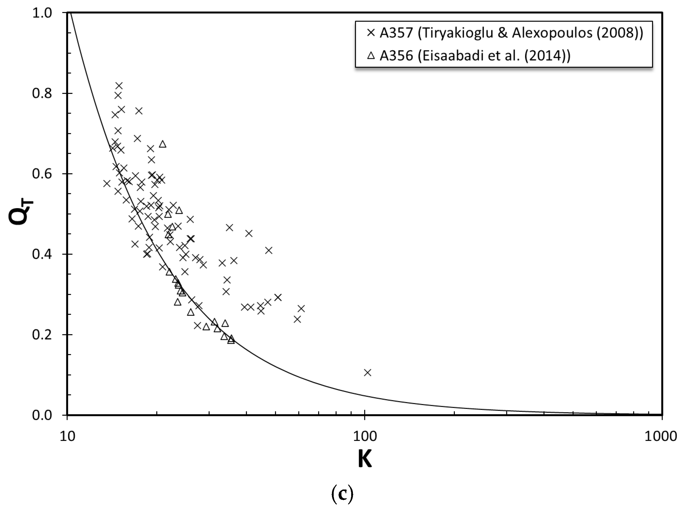
The unitless KM parameter, K, has been previously shown to be correlated with elongation in cast A357 [82] and A356 [85] alloy specimens. An attempt has been made to determine the best fit curve between K and elongation, as well as the structural quality index. Results are presented in Figure 14. Note that both elongation, Figure 14a, and QT, Figure 14b, change with K 4 3 . Best-fit equations in both cases are presented in the respective figures. To determine whether these results are consistent with the previous two studies stated above, QT values have been determined from tensile data in those two studies. Results are presented in Figure 14c. The empirical curve from Figure 14b fits the lower bound of the data from these two independent studies, showing consistency among similar alloys processed completely differently. To the authors’ knowledge, this is the first time K has been shown to correlate with elongation and quality index from multiple studies.

3.7. Correlation Between Si Particle Size and Tensile Deformation

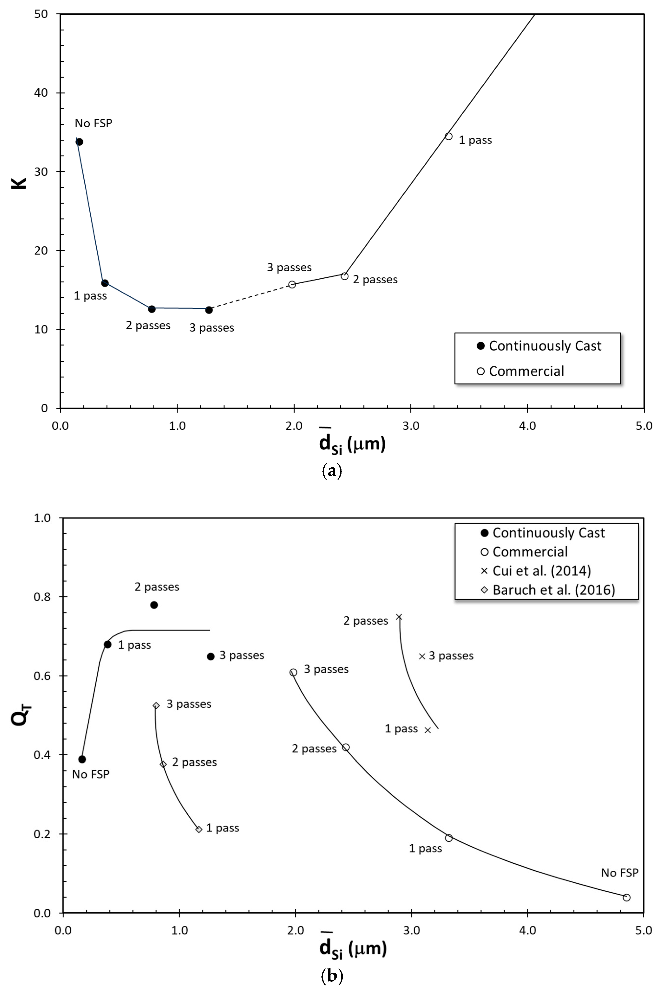
To determine whether the change in tensile deformation behavior is correlated with the microstructural changes characterized previously by the authors [47], the average Si particle sizes presented in Table 1 have been plotted versus the KM parameter K, as presented in Figure 15a. Note that the correlation between Si particle size and K is completely different for the commercial and the continuously cast specimens. In commercial specimens, the reduction in size with each FSP pass is also accompanied by a reduction in K. Conversely, for continuously cast specimens, each FSP pass increases in average Si particle diameter while reducing K. Hence, there is evidence that the improvement in the structural quality in Al-Si alloys due to FSP may not be a result of reduced Si particle size. It is also noteworthy in Figure 15a that if the commercial ingot specimens are to be given more FSP passes, it is likely that the resultant microstructure and the tensile deformation behavior would approach that of FSPed continuously cast specimens, as hypothesized by the dashed line. More research is needed to test this hypothesis.
The correlation between Si particle size and QT for the two types of ingots is presented in Figure 15b. For comparison purposes, data from two other studies [1,86] with multiple FSP passes are also included. Note that the simultaneous reduction in Si particle size and improvement in structural quality are common between commercial ingot specimens in this study, and the findings of Baruch et al. [1] and Cui et al. [86], despite large differences in Si particle sizes between these studies. The correlation between Si particle size and QT for the continuously cast specimens is completely different from the other datasets, providing further evidence that improvement in tensile behavior after FSP is most probably due to the minimization/elimination of bifilms, and not the refinement of Si particles.

4. Conclusions

The results of the present study have demonstrated that:
  • The effect of FSP on microstructure is determined by the as-cast microstructure. When the as-cast microstructure contains acicular Si particles, each FSP pass reduces the size of these particles and their nearest neighbor distance. When the as-cast material has fine Si particles, Si particles coalesce more after each FSP pass, and their nearest neighbor distance increases.
  • There is evidence suggesting that there may be a limiting microstructure that can be reached from both as-cast conditions with more than three FSP passes. Once reached, additional FSP passes would not change the Si particle size or their spacing. More research is needed to test this hypothesis.
  • A clear benefit of FSP is the breaking up of bifilms entrained into the metal in its liquid state, in addition to the refinement and homogenization of the microstructure. The number of passes necessary to eliminate all bifilms is determined by the extent of liquid metal damage in the specimens.
  • With each FSP pass, structural quality has improved progressively in the commercial ingot, as evidenced by an increase in elongation from 1.0 to 18.8% after three FSP passes. In the continuously cast ingot, elongation has almost doubled after the first FSP pass, increasing from 10.9 to 21.1%. However, additional FSP passes have had essentially no effect on elongation.
  • Work hardening characteristics of FSPed specimens have displayed a distinct Stage III work hardening, following the model developed by Kocks and Mecking.
  • Elongation and quality index of all specimens have been correlated with the Kocks–Mecking parameter, K, for the first time, to the authors’ knowledge. The empirical relationship developed in this study is consistent with the data from two independent studies for Al–7 wt.%Si–Mg alloys processed differently.
  • There is evidence that the improvement in elongation and structural quality in Al-Si alloys with FSP may not be due to the refinement of Si particles, but rather to the reduction and elimination of bifilms, i.e., liquid metal damage.

Author Contributions

Conceptualization, M.T. and N.N.; methodology, N.N.; software, P.D.E., N.N.; validation, M.T., N.N. and P.D.E.; formal analysis, M.T. and N.N.; investigation, P.D.E., N.N.; resources, P.D.E.; data curation, M.T. and N.N.; writing—original draft preparation, M.T.; writing—review and editing, M.T., N.N. and P.D.E.; visualization, M.T. and P.D.E.; supervision, M.T.; project administration, M.T.; funding acquisition, M.T. and P.D.E. All authors have read and agreed to the published version of the manuscript.

Funding

This research received no external funding.

Data Availability Statement

The raw data supporting the conclusions of this article will be made available by the authors on request.

Conflicts of Interest

Author Nelson Netto was a graduate student at the University of North Florida when this research was conducted and was employed by the company Saint-Gobain Omniseal Solution. All authors declare that the research was conducted in the absence of any commercial or financial relationships that could be construed as a potential conflict of interest.

References

  1. John Baruch, L.; Raju, R.; Balasubramanian, V.; Rao, A.G.; Dinaharan, I. Influence of Multi-pass Friction Stir Processing on Microstructure and Mechanical Properties of Die Cast Al–7Si–3Cu Aluminum Alloy. Acta Metall. Sin. 2016, 29, 431–440. [Google Scholar] [CrossRef]
  2. Alidokht, S.A.; Abdollah-zadeh, A.; Soleymani, S.; Saeid, T.; Assadi, H. Evaluation of microstructure and wear behavior of friction stir processed cast aluminum alloy. Mater. Charact. 2012, 63, 90–97. [Google Scholar] [CrossRef]
  3. Gangulee, A.; Gurland, J. On the Fracture of Silicon Particles in Aluminum-Silicon Alloys. Trans. TMS-AIME 1967, 239, 269–272. [Google Scholar]
  4. Mueller, M.G.; Fornabaio, M.; Žagar, G.; Mortensen, A. Microscopic strength of silicon particles in an aluminium–silicon alloy. Acta Mater. 2016, 105, 165–175. [Google Scholar] [CrossRef]
  5. Mueller, M.G.; Žagar, G.; Mortensen, A. In-situ strength of individual silicon particles within an aluminium casting alloy. Acta Mater. 2018, 143, 67–76. [Google Scholar] [CrossRef]
  6. Tiryakioğlu, M. Intrinsic and Extrinsic Effects of Microstructure on Properties in Cast Al Alloys. Materials 2020, 13, 2019. [Google Scholar] [CrossRef] [PubMed]
  7. Umeno, Y.; Kushima, A.; Kitamura, T.; Gumbsch, P.; Li, J. Ab initiostudy of the surface properties and ideal strength of (100) silicon thin films. Phys. Rev. B 2005, 72, 165431. [Google Scholar] [CrossRef]
  8. Dubois, S.M.M.; Rignanese, G.M.; Pardoen, T.; Charlier, J.C. Ideal strength of silicon: An ab initio study. Phys. Rev. B 2006, 74, 235203. [Google Scholar] [CrossRef]
  9. Finlayson, T.; Griffiths, J.; Viano, D.; Fitzpatrick, M.; Oliver, E.; Wang, Q. Stresses in the Eutectic Silicon Particles of Strontium-Modified A356 Castings Loaded in Tension. In Proceedings of the Shape Casting: 2nd International Symposium, Orlando, FL, USA, 25 February–1 March 2007; pp. 127–134. [Google Scholar]
  10. Joseph, S.; Kumar, S.; Bhadram, V.S.; Narayana, C. Stress states in individual Si particles of a cast Al–Si alloy: Micro-Raman analysis and microstructure based modeling. J. Alloys Compd. 2015, 625, 296–308. [Google Scholar] [CrossRef]
  11. Harris, S.J.; O’Neill, A.; Boileau, J.; Donlon, W.; Su, X.; Majumdar, B. Application of the Raman technique to measure stress states in individual Si particles in a cast Al–Si alloy. Acta Mater. 2007, 55, 1681–1693. [Google Scholar] [CrossRef]
  12. Mueller, M.G.; Fornabaio, M.; Mortensen, A. Silicon particle pinhole defects in aluminium–silicon alloys. J. Mater. Sci. 2016, 52, 858–868. [Google Scholar] [CrossRef]
  13. Davidson, C.J.; Finlayson, T.R.; Fitzpatrick, M.E.; Griffiths, J.R.; Oliver, E.C.; Wang, Q. Observations of the stress developed in Si inclusions following plastic flow in the matrix of an Al–Si–Mg alloy. Philos. Mag. 2017, 97, 1398–1417. [Google Scholar] [CrossRef]
  14. Campbell, J. Entrainment defects. Mater. Sci. Technol. 2006, 22, 127–145. [Google Scholar] [CrossRef]
  15. Dispinar, D.; Campbell, J. Supercooling of metal in fine filters. J. Mater. Sci. 2007, 42, 10296–10298. [Google Scholar] [CrossRef]
  16. Campbell, J. The Mechanisms of Metallurgical Failure: On the Origin of Fracture; Butterworth-Heinemann: Oxford, UK, 2020. [Google Scholar]
  17. Fox, S.; Campbell, J. Visualisation of oxide film defects during solidification of aluminium alloys. Scr. Mater. 2000, 43, 881–886. [Google Scholar] [CrossRef]
  18. Campbell, J.; Tiryakioğlu, M. Fatigue Failure in Engineered Components and How It Can Be Eliminated: Case Studies on the Influence of Bifilms. Metals 2022, 12, 1320. [Google Scholar] [CrossRef]
  19. Campbell, J. The Origin of Griffith Cracks. Metall. Mater. Trans. B 2011, 42, 1091–1097. [Google Scholar] [CrossRef]
  20. Wang, Q.G. Microstructural effects on the tensile and fracture behavior of aluminum casting alloys A356/357. Metall. Mater. Trans. A 2003, 34, 2887–2899. [Google Scholar] [CrossRef]
  21. Kiser, M.; Zok, F.; Wilkinson, D. Plastic flow and fracture of a particulate metal matrix composite. Acta Mater. 1996, 44, 3465–3476. [Google Scholar] [CrossRef]
  22. Guiglionda, G.; Poole, W.J. The role of damage on the deformation and fracture of Al–Si eutectic alloys. Mater. Sci. Eng. A 2002, 336, 159–169. [Google Scholar] [CrossRef]
  23. Caceres, C.; Griffiths, J. Damage by the cracking of silicon particles in an Al-7Si-0.4 Mg casting alloy. Acta Mater. 1996, 44, 25–33. [Google Scholar] [CrossRef]
  24. Zhang, D.L.; Zheng, L.H.; StJohn, D.H. Effect of solution treatment temperature on tensile properties of AI-7Si-O.3Mg (wt-%) alloy. Mater. Sci. Technol. 2013, 14, 619–625. [Google Scholar] [CrossRef]
  25. Gruzleski, J.E.; Closset, B.M. The Treatment of Liquid Aluminum-Silicon Alloys; American Foundrymen’s Society: Des Plaines, IL, USA, 1990. [Google Scholar]
  26. Mazahery, A.; Shabani, M.O. Modification Mechanism and Microstructural Characteristics of Eutectic Si in Casting Al-Si Alloys: A Review on Experimental and Numerical Studies. JOM 2014, 66, 726–738. [Google Scholar] [CrossRef]
  27. Hanna, M.D.; Lu, S.-Z.; Hellawell, A. Modification in the aluminum silicon system. Metall. Trans. A 1984, 15, 459–469. [Google Scholar] [CrossRef]
  28. Lu, S.-Z.; Hellawell, A. The mechanism of silicon modification in aluminum-silicon alloys: Impurity induced twinning. Metall. Trans. A 1987, 18, 1721–1733. [Google Scholar] [CrossRef]
  29. Alexopoulos, N.D.; Tiryakioğlu, M.; Vasilakos, A.N.; Kourkoulis, S.K. The effect of Cu, Ag, Sm and Sr additions on the statistical distributions of Si particles and tensile properties in A357–T6 alloy castings. Mater. Sci. Eng. A 2014, 604, 40–45. [Google Scholar] [CrossRef]
  30. Kim, M.; Hong, Y.; Cho, H. The effects of Sc on the microstructure and mechanical properties of hypo-eutectic Al−Si alloys. Met. Mater. Int. 2004, 10, 513–520. [Google Scholar] [CrossRef]
  31. Mishra, R.S.; Mahoney, M.; McFadden, S.; Mara, N.; Mukherjee, A. High strain rate superplasticity in a friction stir processed 7075 Al alloy. Scr. Mater. 1999, 42, 163–168. [Google Scholar] [CrossRef]
  32. Mishra, R.S.; Mahoney, M.W. Friction stir processing: A new grain refinement technique to achieve high strain rate superplasticity in commercial alloys. In Proceedings of the Materials Science Forum, Kloster Banz, Germany, 10 October 2001; pp. 507–514. [Google Scholar]
  33. Mishra, R.S.; Ma, Z.Y. Friction stir welding and processing. Mater. Sci. Eng. R Rep. 2005, 50, 1–78. [Google Scholar] [CrossRef]
  34. Jana, S.; Mishra, R.S.; Grant, G. Friction Stir Casting Modification for Enhanced Structural Efficiency: A Volume in the Friction Stir Welding and Processing Book Series; Butterworth-Heinemann: Oxford, UK, 2015. [Google Scholar]
  35. Ma, Z.Y. Friction Stir Processing Technology: A Review. Metall. Mater. Trans. A 2008, 39, 642–658. [Google Scholar] [CrossRef]
  36. Yadav, D.; Bauri, R. Effect of friction stir processing on microstructure and mechanical properties of aluminium. Mater. Sci. Eng. A 2012, 539, 85–92. [Google Scholar] [CrossRef]
  37. Netto, N.; Tiryakioğlu, M.; Eason, P. Characterization of Microstructural Refinement and Hardness Profile Resulting from Friction Stir Processing of 6061-T6 Aluminum Alloy Extrusions. Metals 2018, 8, 552. [Google Scholar] [CrossRef]
  38. Sun, N.; Apelian, D. Defect Elimination in Cast Al Components via Friction Stir Processing. In Proceedings of the TMS 2012 141st Annual Meeting and Exhibition, Materials Properties, Characterization, and Modeling, Orlando, FL, USA, 11–15 March 2012; p. 411. [Google Scholar]
  39. Santella, M.L.; Engstrom, T.; Storjohann, D.; Pan, T.Y. Effects of friction stir processing on mechanical properties of the cast aluminum alloys A319 and A356. Scr. Mater. 2005, 53, 201–206. [Google Scholar] [CrossRef]
  40. Ma, Z.Y.; Sharma, S.R.; Mishra, R.S. Effect of friction stir processing on the microstructure of cast A356 aluminum. Mater. Sci. Eng. A 2006, 433, 269–278. [Google Scholar] [CrossRef]
  41. Kapoor, R.; Rao, V.S.H.; Mishra, R.S.; Baumann, J.A.; Grant, G. Probabilistic fatigue life prediction model for alloys with defects: Applied to A206. Acta Mater. 2011, 59, 3447–3462. [Google Scholar] [CrossRef]
  42. Sharma, S.R.; Ma, Z.Y.; Mishra, R.S. Effect of friction stir processing on fatigue behavior of A356 alloy. Scr. Mater. 2004, 51, 237–241. [Google Scholar] [CrossRef]
  43. Sharma, S.R.; Mishra, R.S. Fatigue crack growth behavior of friction stir processed aluminum alloy. Scr. Mater. 2008, 59, 395–398. [Google Scholar] [CrossRef]
  44. Ammar, H.R.; Samuel, A.M.; Samuel, F.H. Porosity and the fatigue behavior of hypoeutectic and hypereutectic aluminum–silicon casting alloys. Int. J. Fatigue 2008, 30, 1024–1035. [Google Scholar] [CrossRef]
  45. Jana, S.; Mishra, R.S.; Baumann, J.B.; Grant, G. Effect of friction stir processing on fatigue behavior of an investment cast Al–7Si–0.6 Mg alloy. Acta Mater. 2010, 58, 989–1003. [Google Scholar] [CrossRef]
  46. Jana, S.; Mishra, R.S.; Baumann, J.B.; Grant, G. Effect of stress ratio on the fatigue behavior of a friction stir processed cast Al–Si–Mg alloy. Scr. Mater. 2009, 61, 992–995. [Google Scholar] [CrossRef]
  47. Netto, N.; Tiryakioğlu, M.; Eason, P.D. On the Size, Shape and Spatial Distribution of Si Particles in A356 Castings After Single and Multiple Passes of Friction Stir Processing: The Effect of As-Cast Microstructures. Metall. Mater. Trans. A 2021, 52, 5096–5106. [Google Scholar] [CrossRef]
  48. ASTM E8/E8M-22; Standard Test Methods for Tension Testing of Metallic Materials. ASTM International: West Conshohocken, PA, USA, 2024.
  49. Campbell, J. Complete Casting Handbook: Metal Casting Processes, Metallurgy, Techniques and Design, 2nd ed.; Butterworth-Heinemann: Oxford, UK, 2015. [Google Scholar]
  50. Rømming, C.; Hansen, V.; Gjønnes, J. Crystal structure of β-Al4. 5FeSi. Struct. Sci. 1994, 50, 307–312. [Google Scholar]
  51. Hansen, V.; Hauback, B.; Sundberg, M.; Rømming, C.; Gjønnes, J. β-Al4. 5FeSi: A combined synchrotron powder diffraction, electron diffraction, high-resolution electron microscopy and single-crystal X-ray diffraction study of a faulted structure. Struct. Sci. 1998, 54, 351–357. [Google Scholar]
  52. Cao, X.; Campbell, J. The nucleation of Fe-Rich phases on oxide films in Al-11.5Si-0.4Mg cast alloys. Metall. Mater. Trans. A 2003, 34, 1409–1420. [Google Scholar] [CrossRef]
  53. Cao, X.; Campbell, J. Morphology of β-Al5FeSi Phase in Al-Si Cast Alloys. Mater. Trans. 2006, 47, 1303–1312. [Google Scholar] [CrossRef]
  54. Ferdian, D.; Josse, C.; Nguyen, P.; Gey, N.; Ratel-Ramond, N.; de Parseval, P.; Thebault, Y.; Malard, B.; Lacaze, J.; Salvo, L. Chinese Script vs Plate-Like Precipitation of Beta-Al9Fe2Si2 Phase in an Al-6.5Si-1Fe Alloy. Metall. Mater. Trans. A 2015, 46, 2814–2818. [Google Scholar] [CrossRef]
  55. Cao, X.; Saunders, N.; Campbell, J. Effect of iron and manganese contents on convection-free precipitation and sedimentation of primary α-Al(FeMn)Si phase in liquid Al-11.5Si-0.4Mg alloy. J. Mater. Sci. 2004, 39, 2303–2314. [Google Scholar] [CrossRef]
  56. Samuel, A.; Samuel, F.; Doty, H. Observations on the formation of β-Al5FeSi phase in 319 type Al-Si alloys. J. Mater. Sci. 1996, 31, 5529–5539. [Google Scholar] [CrossRef]
  57. Liu, K.; Cao, X.-j.; Chen, X.-G. Precipitation of iron-rich intermetallic phases in Al-4.6 Cu-0.5 Fe-0.5 Mn cast alloy. J. Mater. Sci. 2012, 47, 4290–4298. [Google Scholar] [CrossRef]
  58. Shankar, S.; Riddle, Y.W.; Makhlouf, M.M. Eutectic solidification of aluminum-silicon alloys. Metall. Mater. Trans. A 2004, 35, 3038–3043. [Google Scholar] [CrossRef]
  59. Shankar, S.; Riddle, Y.W.; Makhlouf, M.M. Nucleation mechanism of the eutectic phases in aluminum–silicon hypoeutectic alloys. Acta Mater. 2004, 52, 4447–4460. [Google Scholar] [CrossRef]
  60. Tiryakioğlu, M.; Shuey, R.T. Quench sensitivity of an Al-7 pct Si-0.6 pct Mg alloy: Characterization and modeling. Metall. Mater. Trans. B 2007, 38, 575–582. [Google Scholar] [CrossRef]
  61. Kurz, W.; Fisher, D.J. Fundamentals of Solidification; Trans Tech publications: Aedermannsdorf, Switzerland, 1986; Volume 1. [Google Scholar]
  62. Kirkwood, D. A simple model for dendrite arm coarsening during solidification. Mater. Sci. Eng. 1985, 73, L1–L4. [Google Scholar] [CrossRef]
  63. Samuel, A.; Samuel, F. Effect of alloying elements and dendrite arm spacing on the microstructure and hardness of an Al-Si-Cu-Mg-Fe-Mn (380) aluminium die-casting alloy. J. Mater. Sci. 1995, 30, 1698–1708. [Google Scholar] [CrossRef]
  64. Vorren, O.; Evensen, J.; Pedersen, T. Microstructure and mechanical properties of AlSi (Mg) casting alloys. AFS Trans. 1984, 92, 459–466. [Google Scholar]
  65. Cao, X.; Campbell, J. Oxide inclusion defects in Al-Si-Mg cast alloys. Can. Metall. Q. 2005, 44, 435–448. [Google Scholar] [CrossRef]
  66. DeHoff, R. A geometrically general theory of diffusion controlled coarsening. Acta Metall. Et Mater. 1991, 39, 2349–2360. [Google Scholar] [CrossRef]
  67. Bansal, P.P.; Ardell, A.J. Average nearest-neighbor distances between uniformly distributed finite particles. Metallography 1972, 5, 97–111. [Google Scholar] [CrossRef]
  68. Manoharan, M.; Lewandowski, J.J.; Hunt, W.H. Fracture characteristics of an Al–Si–Mg model composite system. Mater. Sci. Eng. A 1993, 172, 63–69. [Google Scholar] [CrossRef]
  69. Alexopoulos, N.D.; Tiryakioğlu, M. On the uniform elongation of cast Al–7%Si–0.6%Mg (A357) alloys. Mater. Sci. Eng. A 2009, 507, 236–240. [Google Scholar] [CrossRef]
  70. Olofsson, J.; Bogdanoff, T.; Tiryakioğlu, M. On revealing hidden entrainment damage during in situ tensile testing of cast aluminum alloy components. Mater. Charact. 2024, 208, 113647. [Google Scholar] [CrossRef]
  71. Olofsson, J.; Bogdanoff, T.; Tiryakioğlu, M.; Bramann, H.; Sturm, J. The Effect of Hidden Damage on Local Process Variability in Al-10 Pct Si Alloy High-Pressure Die Castings. Metall. Mater. Trans. B 2024, 56, 595–607. [Google Scholar] [CrossRef]
  72. Erzi, E.; Tiryakioğlu, M. A simple procedure to determine incoming quality of aluminum alloy ingots and its application to A356 alloy ingots. Int. J. Met. 2020, 14, 999–1004. [Google Scholar] [CrossRef]
  73. Tiryakioğlu, M.; Yousefian, P.; Eason, P.D. Quantification of Entrainment Damage in A356 Aluminum Alloy Castings. Metall. Mater. Trans. A 2018, 49, 5815–5822. [Google Scholar] [CrossRef]
  74. Taghiabadi, R.; Rostamabadi, A.; Tasvibi, S.; Shaeri, M.H. Increasing the recycling percent in liquid-state recycling of Al machining chips by friction stir processing. Mater. Chem. Phys. 2020, 243, 122627. [Google Scholar] [CrossRef]
  75. Tiryakioğlu, M.; Campbell, J. Quality index for aluminum alloy castings. Int. J. Met. 2014, 8, 39–42. [Google Scholar] [CrossRef]
  76. Tiryakioǧlu, M.; Campbell, J.; Staley, J.T. The influence of structural integrity on the tensile deformation of cast Al–7wt.%Si–0.6wt.%Mg alloys. Scr. Mater. 2003, 49, 873–878. [Google Scholar] [CrossRef]
  77. Meenia, S.; Khan, F.; Babu, S.; Immanuel, R.; Panigrahi, S.; Ram, G.J. Particle refinement and fine-grain formation leading to enhanced mechanical behaviour in a hypo-eutectic Al–Si alloy subjected to multi-pass friction stir processing. Mater. Charact. 2016, 113, 134–143. [Google Scholar] [CrossRef]
  78. Kocks, U. Laws for work-hardening and low-temperature creep. J. Eng. Mater. Technol. 1976, 98, 76–85. [Google Scholar] [CrossRef]
  79. Mecking, H.; Kocks, U. Kinetics of flow and strain-hardening. Acta Metall. 1981, 29, 1865–1875. [Google Scholar] [CrossRef]
  80. Kocks, U.; Mecking, H. Physics and phenomenology of strain hardening: The FCC case. Prog. Mater. Sci. 2003, 48, 171–273. [Google Scholar] [CrossRef]
  81. Tiryakioğlu, M.; Campbell, J.; Alexopoulos, N.D. Quality indices for aluminum alloy castings: A critical review. Metall. Mater. Trans. B 2009, 40, 802–811. [Google Scholar] [CrossRef]
  82. Tiryakioğlu, M.; Alexopoulos, N.D. The Effect of Artificial Aging on Tensile Work Hardening Characteristics of a Cast Al-7 Pct Si-0.55 Pct Mg (A357) Alloy. Metall. Mater. Trans. A 2008, 39, 2772–2780. [Google Scholar] [CrossRef]
  83. Tiryakioğlu, M.; Campbell, J.; Staley, J.T. Evaluating structural integrity of cast Al–7% Si–Mg alloys via work hardening characteristics: 1. Concept of target properties. Mater. Sci. Eng. A 2004, 368, 205–211. [Google Scholar] [CrossRef]
  84. Tiryakioğlu, M.; Staley, J.T.; Campbell, J. The effect of structural integrity on the tensile deformation characteristics of A206-T71 alloy castings. Mater. Sci. Eng. A 2008, 487, 383–387. [Google Scholar] [CrossRef]
  85. Eisaabadi, B.G.; Tiryakioğlu, M.; Davami, P.; Kim, S.-K.; Yoon, Y.O.; Yeom, G.-Y.; Kim, N.-S. The effect of remelting on the melt and casting quality in Al–7%Si–Mg castings. Mater. Sci. Eng. A 2014, 605, 203–209. [Google Scholar] [CrossRef]
  86. Cui, G.; Ni, D.; Ma, Z.; Li, S. Effects of friction stir processing parameters and in situ passes on microstructure and tensile properties of Al-Si-Mg casting. Metall. Mater. Trans. A 2014, 45, 5318–5331. [Google Scholar] [CrossRef]
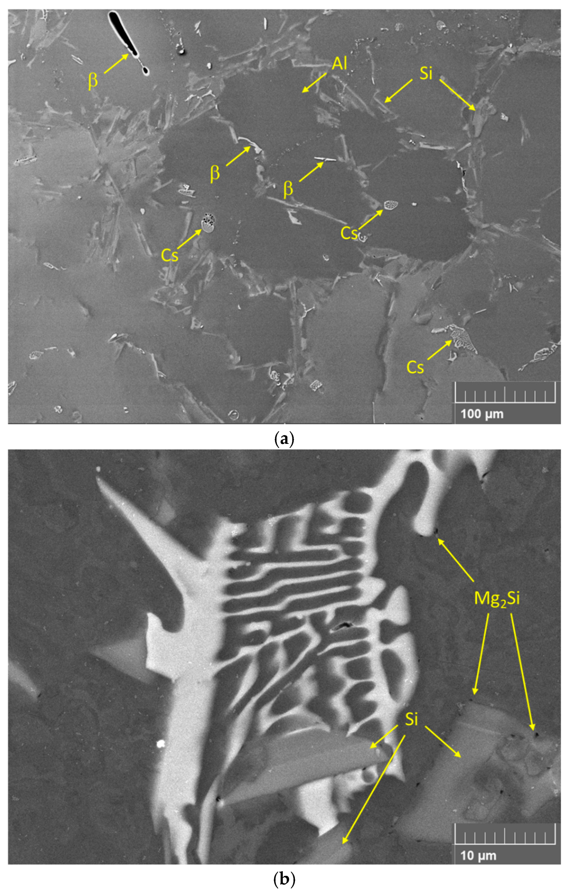
Figure 1. SEM Micrographs of the as-cast microstructure of the commercial f: (a) overall microstructure showing aluminum phase, acicular Si particles, and Fe-bearing constituents (taken in secondary electron imaging mode), and (b) the Chinese script particles that are in contact with at least three Si particles (taken in backscattered electron imaging mode).
Metals 15 01309 g001
Figure 2. SEM Micrographs of the as-cast microstructure of the commercial continuously cast ingot: (a) BSE mode image of overall microstructure showing aluminum phase with a DAS of 14 μm and Fe-bearing particles in brightest contrast in the eutectic areas. The Si particles are too fine to resolve at this magnification, (b) SE image mode of the eutectic Si particles at higher magnification.
Metals 15 01309 g002
Figure 3. SEM Micrograph taken in SE imaging mode of a coarse oxide film found in the continuously cast ingot.
Metals 15 01309 g003
Figure 4. SEM micrographs taken in SE imaging mode illustrating evolution of the microstructure after one FSP pass in (a) commercial, and (b) continuously cast ingot.
Metals 15 01309 g004
Figure 5. SEM Micrographs taken of Microstructure of FSPed specimens after three passes (a) in SE imaging mode for commercial, and (b) in BSE Imaging mode for continuously cast ingots.
Metals 15 01309 g005aMetals 15 01309 g005b
Figure 6. The micrograph (a) and the associated X-ray map for Si (b) in the commercial ingot specimen after 2 FSP passes.
Metals 15 01309 g006aMetals 15 01309 g006b
Figure 7. The relationship between average Si particle diameter and average nearest neighbor distance in commercial and continuously cast ingots. Arrows indicate the progression of FSP passes, with the outermost points representing the as-cast specimens.
Metals 15 01309 g007
Figure 8. Engineering stress–strain plots for tensile tests conducted on as-cast and FSPed specimens from (a) commercial and (b) continuously cast ingot.
Metals 15 01309 g008
Figure 9. The overall fracture surface of the commercial ingot specimen after three FSP passes.
Metals 15 01309 g009
Figure 10. SEM fractographs taken in SE imaging mode of fracture surfaces of as-cast specimens from (a) a commercial A356 specimen showing a faceted fracture and (b) a continuously ingot showing the fracture along the Si eutectic region.
Metals 15 01309 g010aMetals 15 01309 g010b
Figure 11. SEM fractographs taken in SE imaging mode of specimens after 1 FSP pass of (a) commercial and (b) continuously cast A356 sample.
Metals 15 01309 g011aMetals 15 01309 g011b
Figure 12. Kocks–Mecking (KM) analysis for as-cast (a) and after 1 (b), 2 (c), and 3 (d) FSP passes for the commercial ingot, showing the presence of Stage III work hardening only after FSP.
Metals 15 01309 g012aMetals 15 01309 g012b
Figure 13. Kocks–Mecking (KM) analysis for (a) as-cast and after (b) 1, (c) 2, and (d) 3 FSP passes for the continuously cast ingot specimens.
Metals 15 01309 g013aMetals 15 01309 g013b
Figure 14. The effect of Kocks–Mecking parameter, K, on (a) elongation, and (b) structural quality index. The curve shown in (b) is compared with data from previous studies [82,85] in (c).
Metals 15 01309 g014aMetals 15 01309 g014b
Figure 15. The correlation between Si particle size and (a) the KM parameter K, and (b) QT for the continuous cast and commercial ingot in the present and previous studies [1,86].
Metals 15 01309 g015
Table 1. The averages for equivalent diameter ( d ¯ e q ) and nearest neighbor distance ( L ¯ n n ) for as-cast and the three FSP conditions in the two types of ingots, as reported in Ref. [47].
CommercialContinuously Cast
FSP Passes d ¯ e q ( μ m ) L ¯ n n ( μ m ) d ¯ e q ( μ m ) L ¯ n n ( μ m )
04.8527.7030.1610.244
13.3146.8260.3790.980
22.4275.0070.7811.284
31.9735.0301.2672.157
Table 2. Experimental tensile data for as-cast and FSPed specimens for the two types of ingots.
MaterialFSP Passσy (MPa)ST (MPa)eF (%)QT
Commercial0153.7175.31.00.04
191.1141.45.80.19
278.2152.813.00.42
381.9154.418.80.61
Continuously cast0121.0221.010.90.39
179.5153.721.10.68
275.5157.024.00.78
377.9155.220.90.65
Table 3. Results of Kocks–Mecking analysis for all specimens.
IngotFSP PassesKθ0 (MPa)
Commercial0250.0 *47413 *
134.55523
216.83034
315.72872
Continuously Cast033.88129
115.92888
212.62438
312.52396
*: fracture occurred in Stage II work hardening.
Disclaimer/Publisher’s Note: The statements, opinions and data contained in all publications are solely those of the individual author(s) and contributor(s) and not of MDPI and/or the editor(s). MDPI and/or the editor(s) disclaim responsibility for any injury to people or property resulting from any ideas, methods, instructions or products referred to in the content.