

Microstructure, Mechanical Properties, and Fatigue Resistance of an Al-Mg-Sc-Zr Alloy Fabricated by Wire Arc Additive Manufacturing


Abstract
1. Introduction
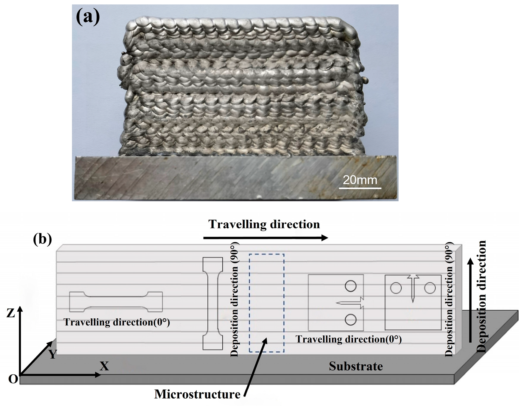
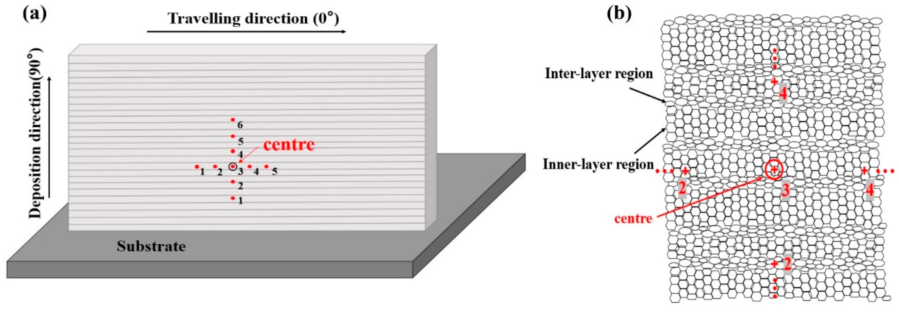
2. Material and Methods
3. Results
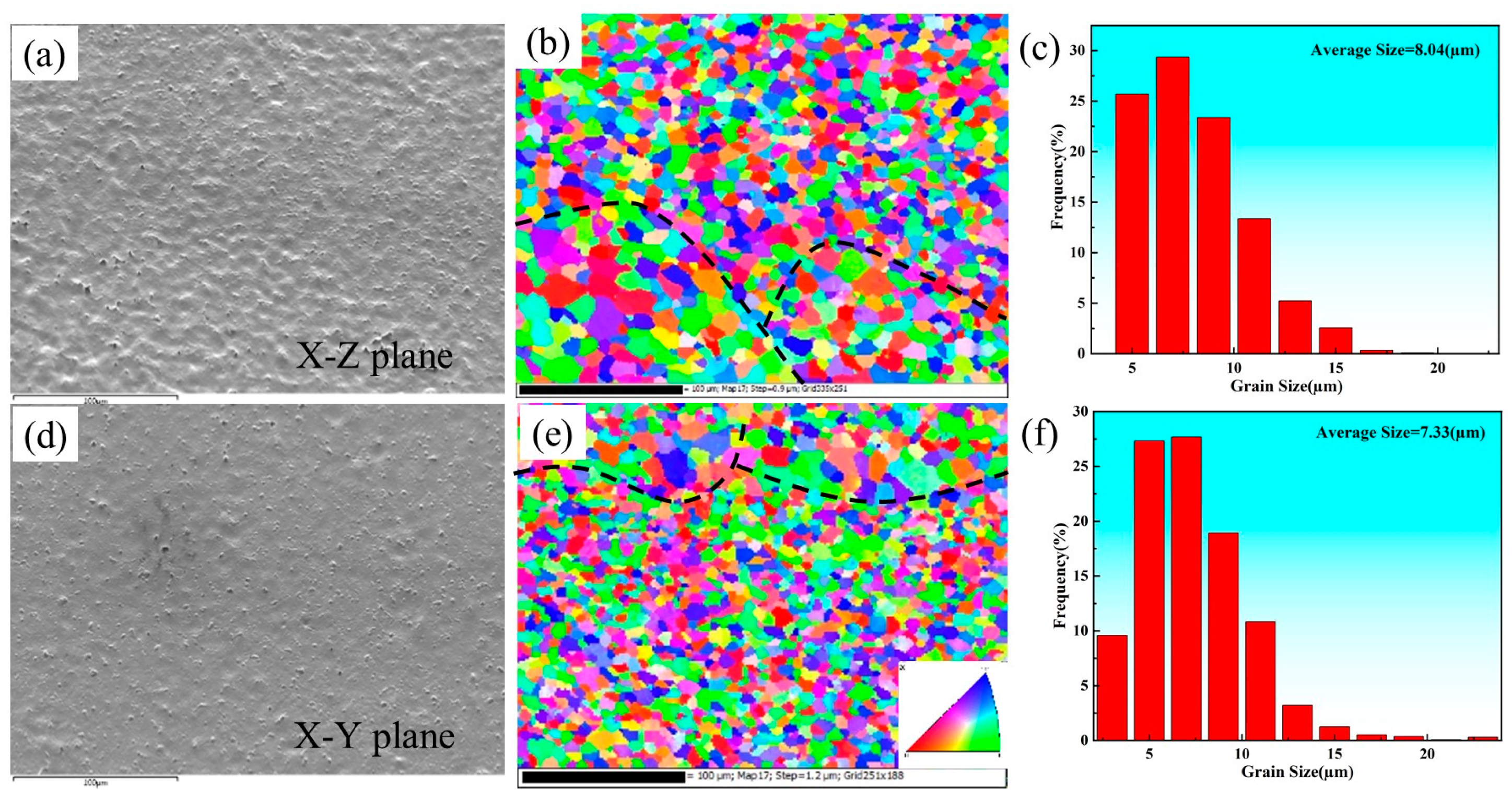
3.1. Microstructure
3.2. Mechanical Properties
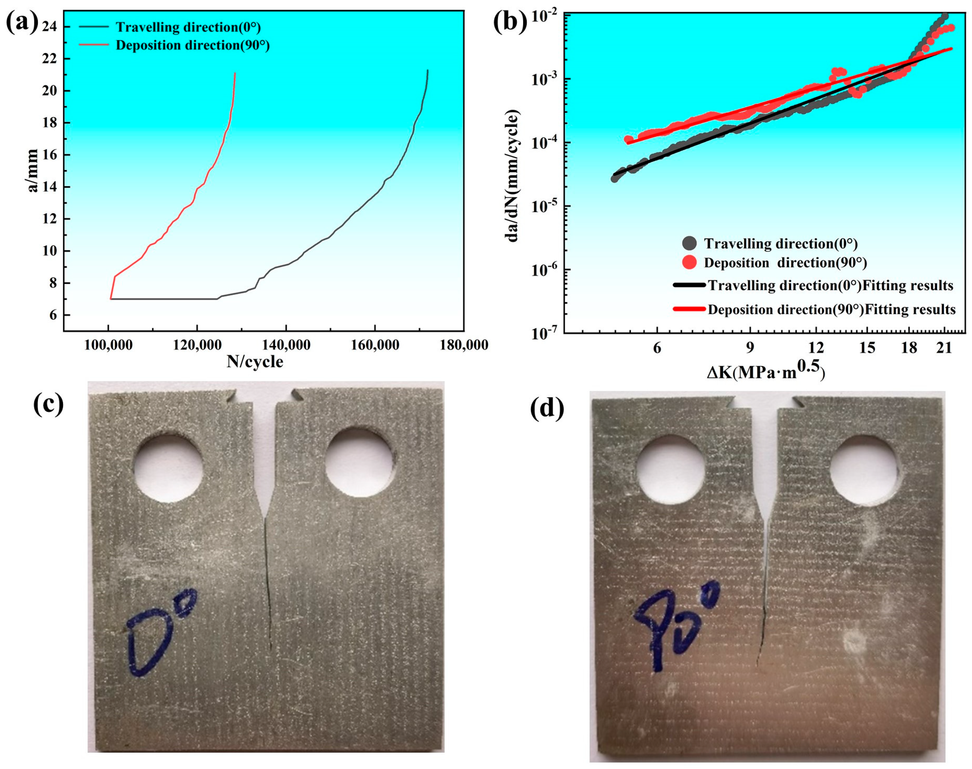
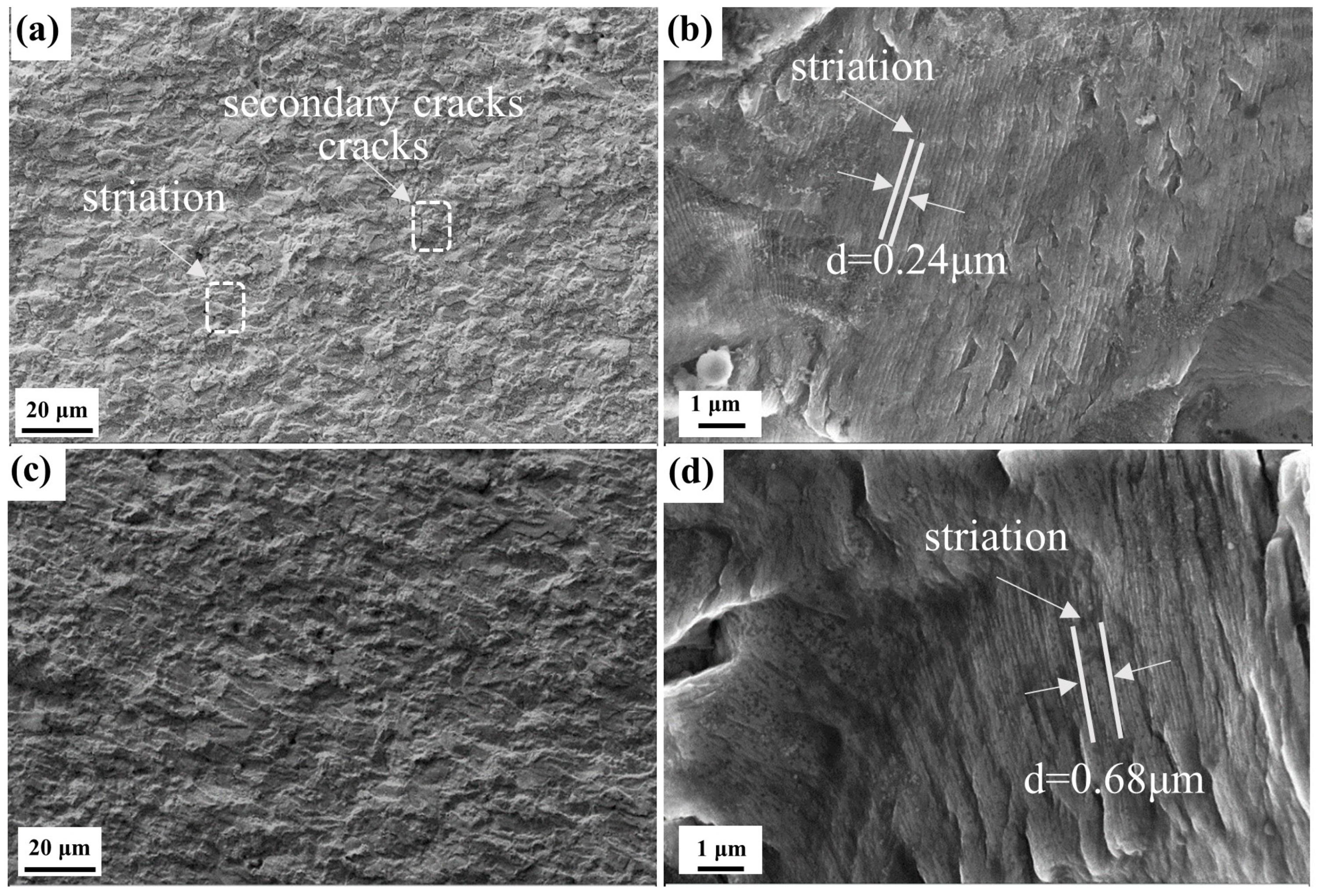
3.3. Fatigue Crack Growth Behavior
4. Discussion
5. Conclusions
- (1)
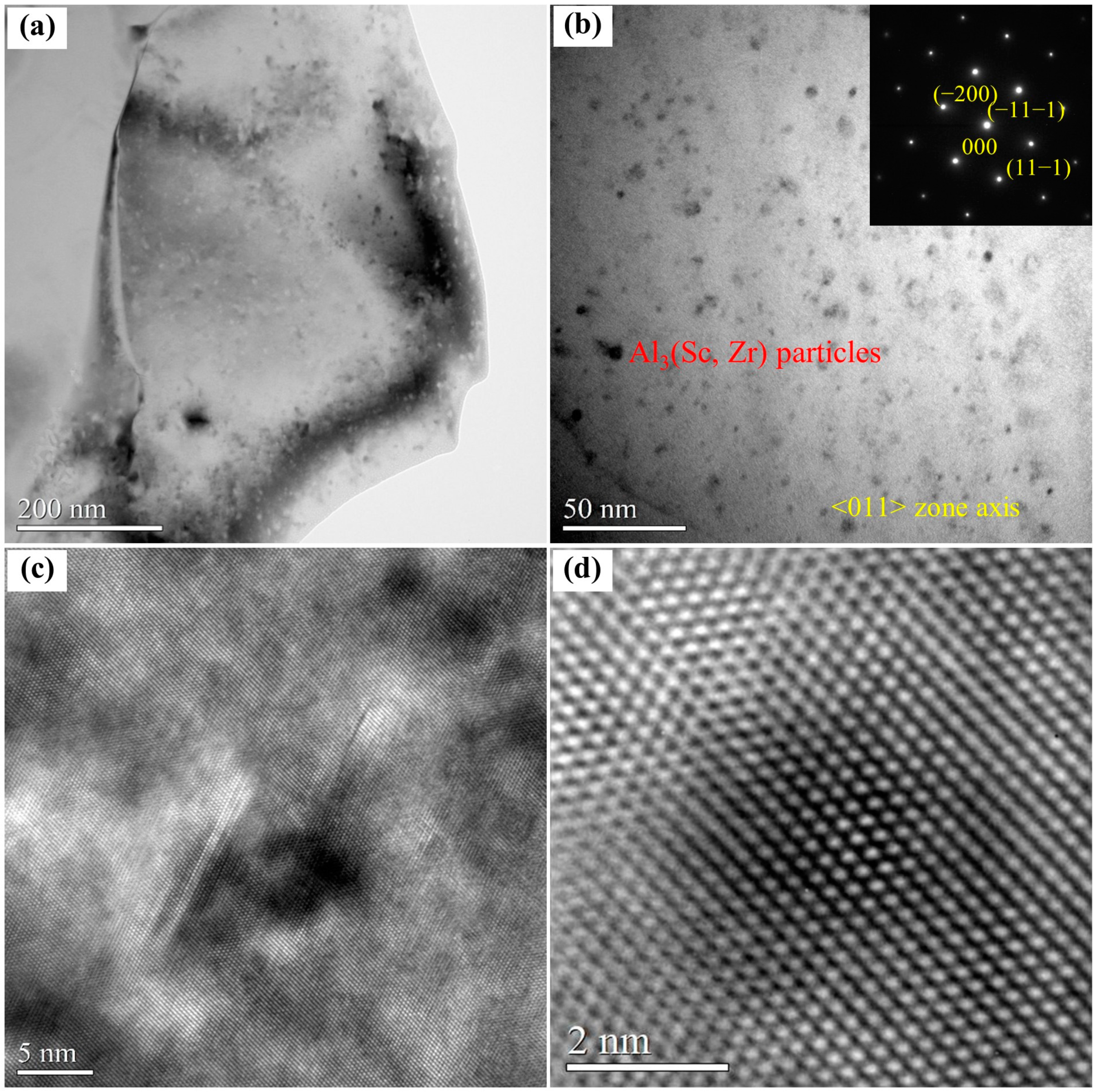
- The microstructure of the as-deposited Al-Mg-Sc-Zr alloy is composed of fine equiaxed grains with an average grain size of around 8 μm due to the formation of the primary Al3(Sc, Zr) particles with a sub-micron size. Meanwhile, the nanosized Al3(Sc, Zr) phase with a size of about 5 nm is also evident and plays an important role in strengthening the alloy.
- (2)
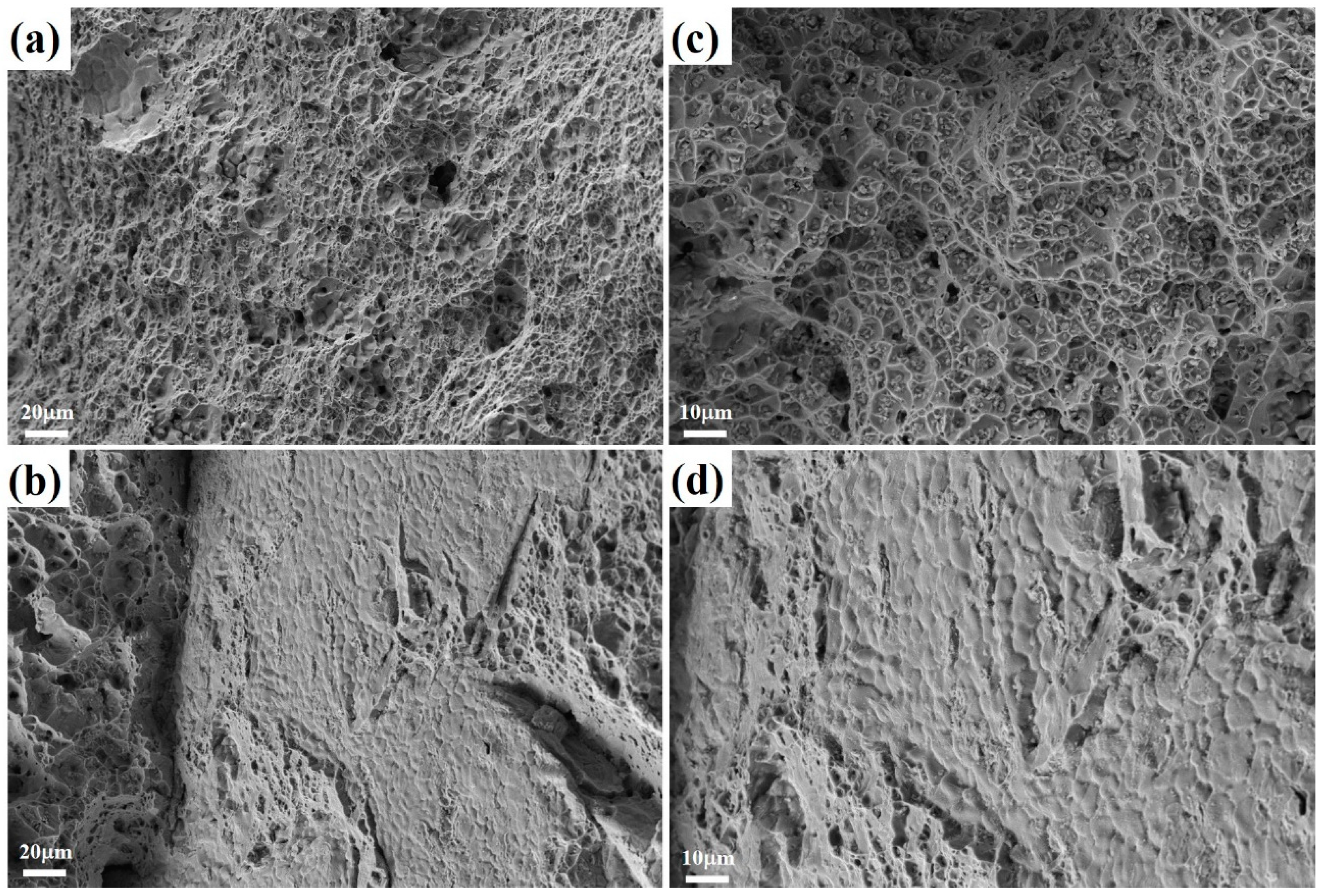
- The mechanical properties of the as-deposited alloy show significant anisotropy, and the comprehensive mechanical properties of the traveling direction are better than those of the deposition direction. The UTS, YS, and EL of the sample along the 0° direction are 362 ± 7 MPa, 244 ± 3 MPa, and 24.81 ± 0.3%, respectively, while those of the sample along the 90° direction are 274 ± 5 MPa, 213 ± 4 MPa, and 7.22 ± 0.2%. The weak bonding zones are found on the fracture surface of the sample along the 90° direction and may have a negative impact on the mechanical properties.
- (3)
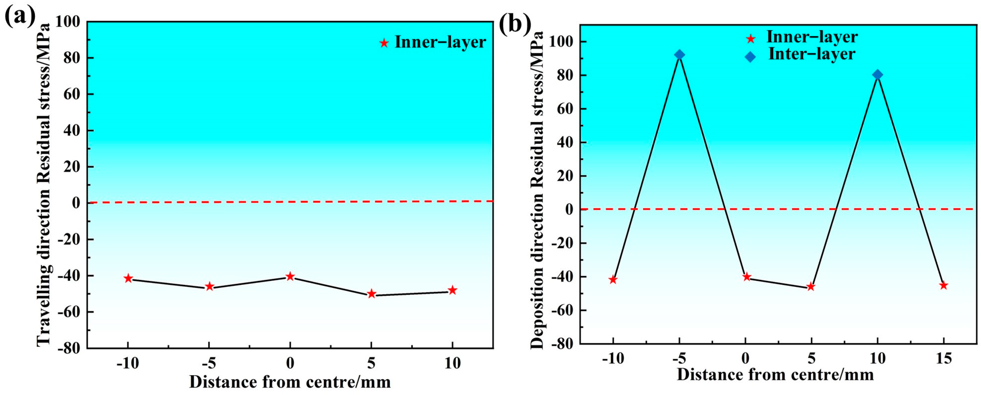
- The critical fatigue life of the as-deposited alloy along the traveling direction (0° direction) is 1.72 × 10⁵, which is better than that of the alloy along the deposition direction (90° direction). The presence of weak bonding areas and high tensile (positive) residual stress between the deposition layers deteriorate the critical fatigue life of the sample along the deposition direction (90° direction).
Author Contributions
Funding
Data Availability Statement
Conflicts of Interest
References
- Li, S.; Yue, X.; Li, Q.; Peng, H.; Dong, B.; Liu, T.; Yang, H.; Fan, J.; Shu, S.; Qiu, F.; et al. Development and applications of aluminum alloys for aerospace industry. J. Mater. Res. Technol. 2023, 27, 944–983. [Google Scholar] [CrossRef]
- Omiyale, B.O.; Olugbade, T.O.; Abioye, T.E.; Farayibi, P.K. Wire arc additive manufacturing of aluminium alloys for aerospace and automotive applications: A review. Mater. Sci. Technol. 2022, 38, 391–408. [Google Scholar] [CrossRef]
- Athaib, N.H.; Haleem, A.H.; Al-Zubaidy, B. A review of Wire Arc Additive Manufacturing (WAAM) of Aluminium Composite, Process, Classification, Advantages, Challenges, and Application. J. Phys. Conf. Ser. 2021, 1973, 012083. [Google Scholar] [CrossRef]
- Çam, G. Prospects of producing aluminum parts by wire arc additive manufacturing (WAAM). Mater. Today Proc. 2022, 62, 77–85. [Google Scholar] [CrossRef]
- Miao, J.; Chen, J.; Ren, J.; Luo, Z.; Fan, Z.; Zhou, Z.; Xing, T.; Guan, R. Wire-arc additive manufactured Al-Cu alloy: Microstructure, mechanical properties and their anisotropy. Mater. Sci. Technol. 2023, 39, 2124–2134. [Google Scholar] [CrossRef]
- Guo, Y.; Han, Q.; Hu, J.; Yang, X.; Mao, P.; Wang, J.; Sun, S.; He, Z.; Lu, J.; Liu, C. Comparative Study on Wire-Arc Additive Manufacturing and Conventional Casting of Al-Si Alloys: Porosity, Microstructure and Mechanical Property. Acta Metall. Sin. (Engl. Lett.) 2022, 35, 475–485. [Google Scholar] [CrossRef]
- Liu, Y.; Liu, Z.; Zhou, G.; He, J.; Zhang, J. Microstructures and Properties of Al-Mg Alloys Manufactured by WAAM-CMT. Materials 2022, 15, 5460. [Google Scholar] [CrossRef]
- Xing, T.; Chen, J.; Miao, J.; Hu, W.; Ren, J.; Guan, R. Microstructure and mechanical properties of Al-Mg-Si/Al-Mg-Sc laminated composite fabricated by wire-arc directed energy deposition. Mater. Sci. Eng. A 2024, 894, 146194. [Google Scholar] [CrossRef]
- Xu, S.; Lei, D.; Yang, X.; Lu, X.; Chen, J.; Li, M. Wire arc additive manufacturing of components using TiC/Ti reinforced Al-Zn-Mg-Cu alloy wire: Microstructure evolution, strengthening mechanism, and fracture behavior. Mater. Charact. 2024, 217, 114452. [Google Scholar] [CrossRef]
- Holmestad, J.; Marioara, C.D.; Myrold, B.J.; Jensrud, O. The Effect of Deformation and Isothermal Heat Treatment of a 5005 Aluminum Alloy. Metals 2024, 14, 225. [Google Scholar] [CrossRef]
- Kondo, M.; Suzuki, T.; Li, R.; Takata, N. Improved high-temperature creep properties of heat-resistant Al-Mg-Zn-Cu-Ni quinary alloy by adding a trace amount of Ti. J. Jpn. Inst. Light Met. 2023, 73, 260–265. [Google Scholar] [CrossRef]
- Ji, J.; Wang, L.; Lyu, F.; Gao, Z.; Zhan, X. Strength-ductility synergy of deposited Al-Mg-Sc alloy with a homogeneous phase distribution brought by heat treatment. Mater. Sci. Eng. A 2024, 913, 147034. [Google Scholar] [CrossRef]
- Lasagni, F.; Galleguillos, C.; Herrera, M.; Santaolaya, J.; Hervás, D.; González, S.; Periñán, A. On the processability and mechanical behavior of Al-Mg-Sc alloy for PBF-LB. Prog. Addit. Manuf. 2022, 7, 29–39. [Google Scholar] [CrossRef]
- Menglong, H. An SLM-processed Er- and Zr- modified Al-Mg alloy: Microstructure and mechanical properties at room and elevated temperatures. Mater. Sci. Eng. A 2023, 883, 145485. [Google Scholar]
- Bi, J.; Lei, Z.; Chen, Y.; Chen, X.; Tian, Z.; Qin, X.; Liang, J.; Zhang, X. Effect of Al3(Sc, Zr) and Mg2Si precipitates on microstructure and tensile properties of selective laser melted Al-14.1Mg-0.47Si-0.31Sc-0.17Zr alloy. Intermetallics 2020, 123, 106822. [Google Scholar] [CrossRef]
- Wang, Z.; Zeng, L.; Lin, X.; Wang, J.; Feng, Z.; Dong, C.; Li, H.; Wang, Y.; Huang, W. Microstructural evolution and strengthening mechanisms of additively-manufactured Al-Mg-Sc-Zr alloys: Laser directed energy deposition versus laser powder bed fusion. J. Alloys Compd. 2024, 985, 173946. [Google Scholar] [CrossRef]
- Bayoumy, D.; Schliephake, D.; Dietrich, S.; Wu, X.; Zhu, Y.; Huang, A. Intensive processing optimization for achieving strong and ductile Al-Mn-Mg-Sc-Zr alloy produced by selective laser melting. Mater. Des. 2021, 198, 109317. [Google Scholar] [CrossRef]
- Agrawal, P.; Gupta, S.; Thapliyal, S.; Shukla, S.; Haridas, R.; Mishra, R. Additively manufactured novel Al-Cu-Sc-Zr alloy: Microstructure and mechanical properties. Addit. Manuf. 2020, 37, 101623. [Google Scholar] [CrossRef]
- Guo, X.; Li, H.; Xue, P.; Pana, Z.; Xu, R.; Ni, D.; Ma, Z. Microstructure and mechanical properties of 600 MPa grade ultra-high strength aluminum alloy fabricated by wire-arc additive manufacturing. J. Mater. Sci. Technol. 2023, 149, 56–66. [Google Scholar] [CrossRef]
- Hou, X.; Zhao, L.; Ren, S.; Peng, Y.; Ma, C.; Tian, Z.; Qu, X. A comparative study on Al-Mg-Sc-Zr alloy fabricated by wire arc additive manufacturing with controlling interlayer temperature and continuous printing: Porosity, microstructure, and mechanical properties. J. Mater. Sci. Technol. 2024, 193, 199–216. [Google Scholar] [CrossRef]
- Miao, J.; Chen, J.; Ting, X.; Hu, W.; Ren, J.; Li, T.; Zeng, L.; Guan, R.; Ojo, O. Effect of solution treatment on porosity, tensile properties and fatigue resistance of Al-Cu alloy fabricated by wire arc additive manufacturing. J. Mater. Res. Technol. 2024, 28, 1864–1874. [Google Scholar] [CrossRef]
- He, C.; Wei, J.; Li, Y.; Zhang, Z.; Tian, N.; Qin, G.; Zuo, L. Improvement of microstructure and fatigue performance of wire-arc additive manufactured 4043 aluminum alloy assisted by interlayer friction stir processing. J. Mater. Sci. Technol. 2023, 133, 183–194. [Google Scholar] [CrossRef]
- Li, D.; Li, S.; Zhang, Z.; Chen, J.; Zhang, Y.; Yang, J.; Li, W.; Li, W.; Li, Y.; Ojo, O. Regulate the microstructure, tensile properties and fatigue crack growth behavior of an Al-Zn-Mg-Cu alloys fabricated by laser powder bed fusion via post-heat treatment. J. Mater. Res. Technol. 2023, 27, 6947–6960. [Google Scholar] [CrossRef]
- GB/T 228.1-2021; Metallic Materials-Tensile Testing at Ambient Temperature. China Market Supervision and Administration Publishing House: Beijing, China, 2021.
- Zhou, Z.; Chen, J.; Ren, J.; Miao, J.; Xing, T.; Zhong, S.; Guan, R. Tensile, Fatigue Properties and Their Anisotropies of Al-Mg Alloy Fabricated by Wire-Arc Additive Manufacturing. 3d Print. Addit. Manuf. 2024, 11, 1324–1333. [Google Scholar] [CrossRef]
- Nunes, A.; Gouveia, G.; Spinelli, J. Solidification, α-Al morphologies, and tensile properties of low-Sc modified Al-Mg alloys. Mater. Charact. 2023, 206, 113416. [Google Scholar] [CrossRef]
- Zhou, Z.; Chen, J.; Wen, F.; Han, S.; Zhong, S.; Qi, L.; Guan, R. Optimization of heat treatment for an Al–Mg–Sc–Mn–Zr alloy with ultrafine grains manufactured by laser powder bed fusion. Mater. Charact. 2022, 189, 111977. [Google Scholar] [CrossRef]
- Jiang, H.; Zhang, Q.; Wu, X.; Fan, J. Jinghong. Spatiotemporal aspects of the Portevin-Le Chatelier effect in annealed and solution-treated aluminum alloys. Scr. Mater. 2006, 54, 2041–2045. [Google Scholar] [CrossRef]
- Qiu, Y.; Yang, X.; Li, J.; Xiang, S.; Xu, J.; Sanders, R. Portevin-Le Chatelier behavior in Al-Mg-Sc-Zr alloys: Effects of Al3(Sc, Zr) dispersoid distribution and grain structure. Mater. Sci. Eng. A 2024, 908, 146919. [Google Scholar] [CrossRef]
- Wang, J.; Zhu, K.; Zhang, W.; Zhu, X.; Lu, X. Microstructural and Defect Evolution during WAAM Resulting in Mechanical Property Differences for AA5356 Component. J. Mater. Res. Technol. 2022, 22, 982–996. [Google Scholar] [CrossRef]
- Pan, J.; Yuan, B.; Ge, J.; Ren, Y.; Chen, H.; Zhang, L.; Lu, H. Influence of arc mode on the microstructure and mechanical properties of 5356 aluminum alloy fabricated by wire arc additive manufacturing. J. Mater. Res. Technol. 2022, 20, 1893–1907. [Google Scholar]
- Su, C.; Chen, X.; Gao, C.; Wang, Y. Effect of heat input on microstructure and mechanical properties of Al-Mg alloys fabricated by WAAM. Appl. Surf. Sci. 2019, 486, 431–440. [Google Scholar] [CrossRef]
- Panchenko, O.; Kurushkin, D.; Mushnikov, I.; Khismatullin, A.; Popovich, A. A high-performance WAAM process for Al-Mg-Mn using controlled short-circuiting metal transfer at increased wire feed rate and increased travel speed. Mater. Des. 2020, 195, 109040. [Google Scholar] [CrossRef]
- Xia, Y.; Cai, X.; Dong, B.; Lin, S. Wire arc additive manufacturing of Al-Mg-Sc alloy: An analysis of the effect of Sc on microstructure and mechanical properties. Mater. Charact. 2023, 203, 113116. [Google Scholar] [CrossRef]
- Yi, M.; Tang, W.; Zhu, Y.; Liang, C.; Tang, Z.; Yin, Y.; He, W.; Sun, S.; Su, S. A holistic review on fatigue properties of additively manufactured metals. J. Mater. Process. Technol. 2024, 329, 118425. [Google Scholar] [CrossRef]
- Zhai, T.; Wilkinson, A.J.; Martin, J.W. A crystallographic mechanism for fatigue crack propagation through grain boundaries. Acta Mater. 2000, 48, 4917–4927. [Google Scholar] [CrossRef]
- Xu, Y.; Cong, J.; Wang, L.; Hui, L. Effect of Ultrasonic Impact on Corrosion Fatigue Properties of Titanium Alloy Welded Joints. J. Mater. Eng. Perform. 2023, 32, 7204–7214. [Google Scholar]
- Suominen, L.; Khurshid, M.; Parantainen, J. Residual stresses in welded components following post-weld treatment methods. Procedia Eng. 2013, 66, 181–191. [Google Scholar] [CrossRef]
- Hosseini, S.; Farajollahi, M.; Ebrahimi, M. Residual stress, fatigue behavior, and mechanical properties of equal-channel angular pressed commercial pure titanium. J. Mater. Res. Technol. 2024, 28, 3297–3305. [Google Scholar] [CrossRef]
- Su, K.; Zhang, J.; Lu, L.; Li, H.; Ji, D. Corrosion-fatigue property of anodic oxidation coated 6082-T6 aluminium alloy: Effect of substrate residual stress and microstructure beneath coating-substrate interface. Int. J. Fatigue 2023, 175, 107803. [Google Scholar] [CrossRef]


| Element | Mg | Sc | Zr | Fe | Cr | Si | Ti | Al |
| Content | 6.09 | 0.28 | 0.15 | 0.13 | 0.1 | 0.09 | 0.06 | Bal |
| Welding Wire | Scanning Speed | Wire Feeding Speed | Welding Current |
|---|---|---|---|
| Al-Mg-Sc-Zr alloy | 1.8 m/min | 8 m/min | 160 A |
| Element | Al | Mg | Sc | Zr | Fe | Si |
|---|---|---|---|---|---|---|
| A1 | 84.33 | 5.72 | 5.48 | 4.38 | 0.09 | - |
| A2 | 88.76 | 6.03 | 3.46 | 1.71 | 0.04 | - |
| A3 | 91.33 | 5.91 | 0.17 | 0.29 | 2.30 | - |
| A4 | 90.54 | 6.58 | 0.27 | 0.35 | 2.24 | 0.02 |
| A5 | 90.32 | 5.38 | 1.10 | 0.15 | 0.23 | 2.82 |
| Alloys | UTS (MPa) | YS (MPa) | EL (%) |
|---|---|---|---|
| Al-4.7Mg [25] | 258 | 141 | 21.3 |
| Al-4.8Mg [30] | 286 | 142 | 23.0 |
| Al-5.0Mg [31] | 263 | 172 | 20.9 |
| Al-5.2Mg [32] | 257 | 128 | 20.2 |
| Al-5.8Mg-0.8Mn [33] | 314 | 164 | 34.0 |
| Al-6.5Mg-0.7Mn-0.3Sc-0.1Ti [12] | 392 | 221 | 26.5 |
| Al-6.54Mg-0.36Sc-0.1Zr [19] | 336 | 171 | 24.8 |
| Al-6.3Mg-0.3Sc-0.1Zr [34] | 335 | 183 | 22.5 |
| Al-6.09Mg-0.28Sc-0.15Zr (this work) | 362 | 244 | 24.8 |
| Sample | C | m | R | ΔKth |
|---|---|---|---|---|
| 0° direction | 2.09 × 10⁻⁷ | 3.12 | 0.957 | 0.790 |
| 90° direction | 1.71 × 10⁻⁶ | 2.43 | 0.938 | 0.309 |
Disclaimer/Publisher’s Note: The statements, opinions and data contained in all publications are solely those of the individual author(s) and contributor(s) and not of MDPI and/or the editor(s). MDPI and/or the editor(s) disclaim responsibility for any injury to people or property resulting from any ideas, methods, instructions or products referred to in the content. |
© 2025 by the authors. Licensee MDPI, Basel, Switzerland. This article is an open access article distributed under the terms and conditions of the Creative Commons Attribution (CC BY) license (https://creativecommons.org/licenses/by/4.0/).
Share and Cite
Zeng, L.; Chen, J.; Li, T.; Tuo, Z.; Zheng, Z.; Wu, H. Microstructure, Mechanical Properties, and Fatigue Resistance of an Al-Mg-Sc-Zr Alloy Fabricated by Wire Arc Additive Manufacturing. Metals 2025, 15, 31. https://doi.org/10.3390/met15010031
Zeng L, Chen J, Li T, Tuo Z, Zheng Z, Wu H. Microstructure, Mechanical Properties, and Fatigue Resistance of an Al-Mg-Sc-Zr Alloy Fabricated by Wire Arc Additive Manufacturing. Metals. 2025; 15(1):31. https://doi.org/10.3390/met15010031
Chicago/Turabian StyleZeng, Lingpeng, Jiqiang Chen, Tao Li, Zhanglong Tuo, Zuming Zheng, and Hanlin Wu. 2025. "Microstructure, Mechanical Properties, and Fatigue Resistance of an Al-Mg-Sc-Zr Alloy Fabricated by Wire Arc Additive Manufacturing" Metals 15, no. 1: 31. https://doi.org/10.3390/met15010031
APA StyleZeng, L., Chen, J., Li, T., Tuo, Z., Zheng, Z., & Wu, H. (2025). Microstructure, Mechanical Properties, and Fatigue Resistance of an Al-Mg-Sc-Zr Alloy Fabricated by Wire Arc Additive Manufacturing. Metals, 15(1), 31. https://doi.org/10.3390/met15010031