
Investigation of the Machined Surface Integrity of WC-High-Entropy Alloy Cemented Carbide


 and
and 
Abstract
1. Introduction
2. Materials and Experimental Procedures
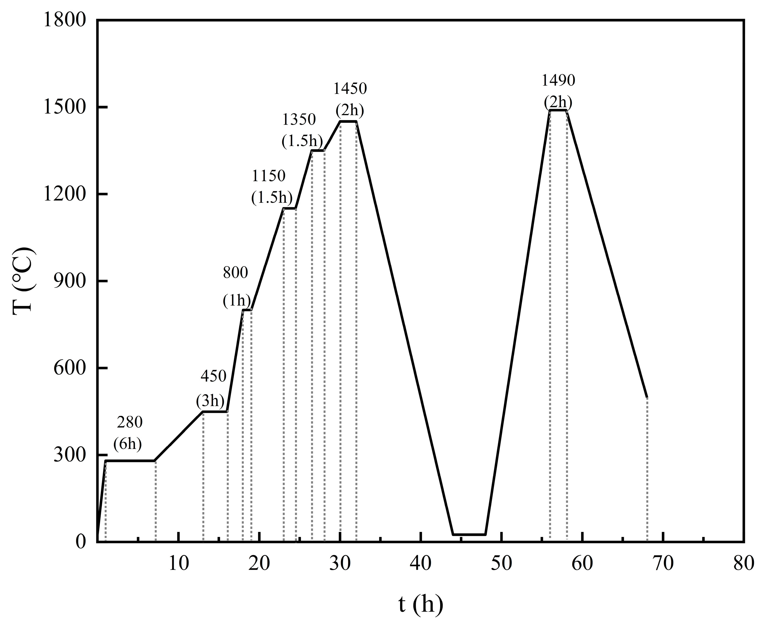
2.1. Experimental Material
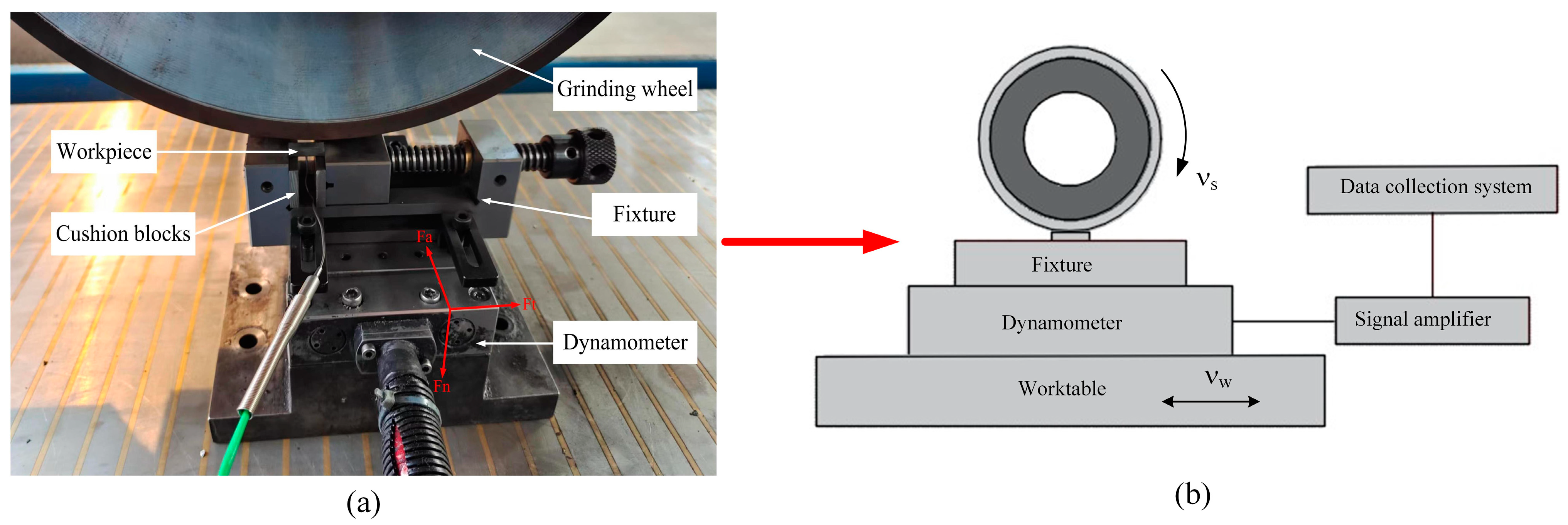
2.2. Grinding Procedure
2.3. Ground Surface Integrity Test
3. Results and Discussion
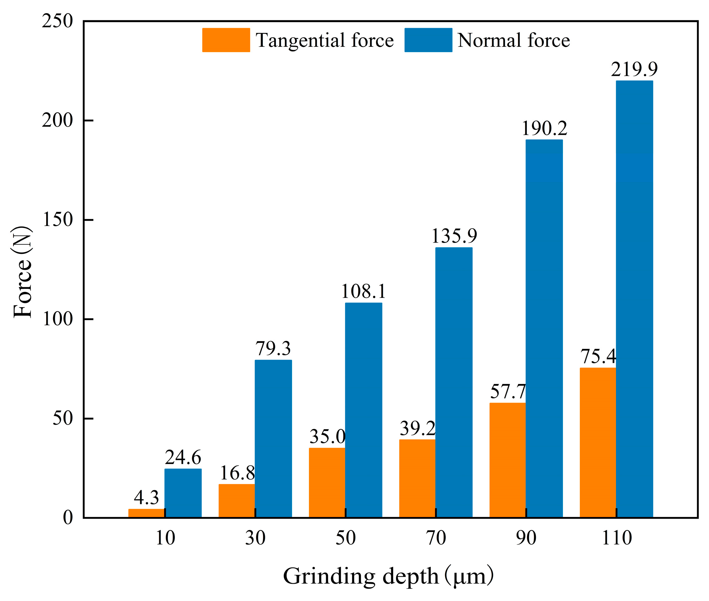
3.1. Grinding Force
3.2. Surface Morphology and Material Removal Mechanism
3.3. Surface Roughness
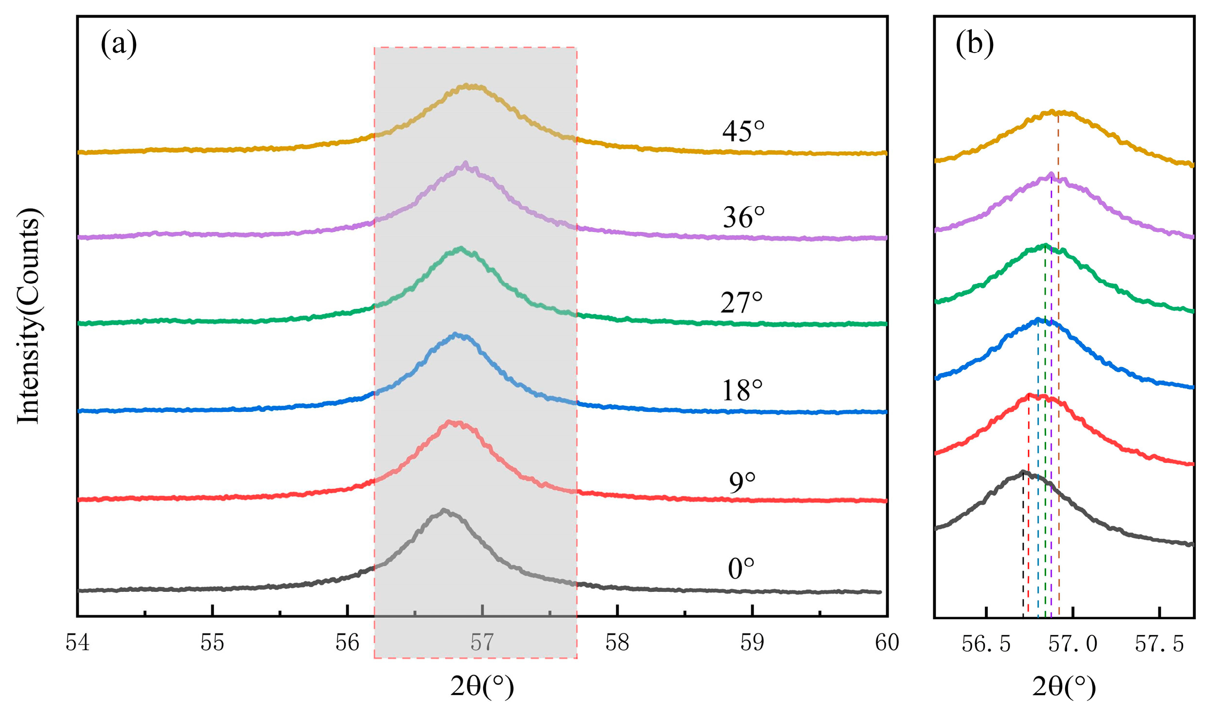
3.4. Surface Residual Stress
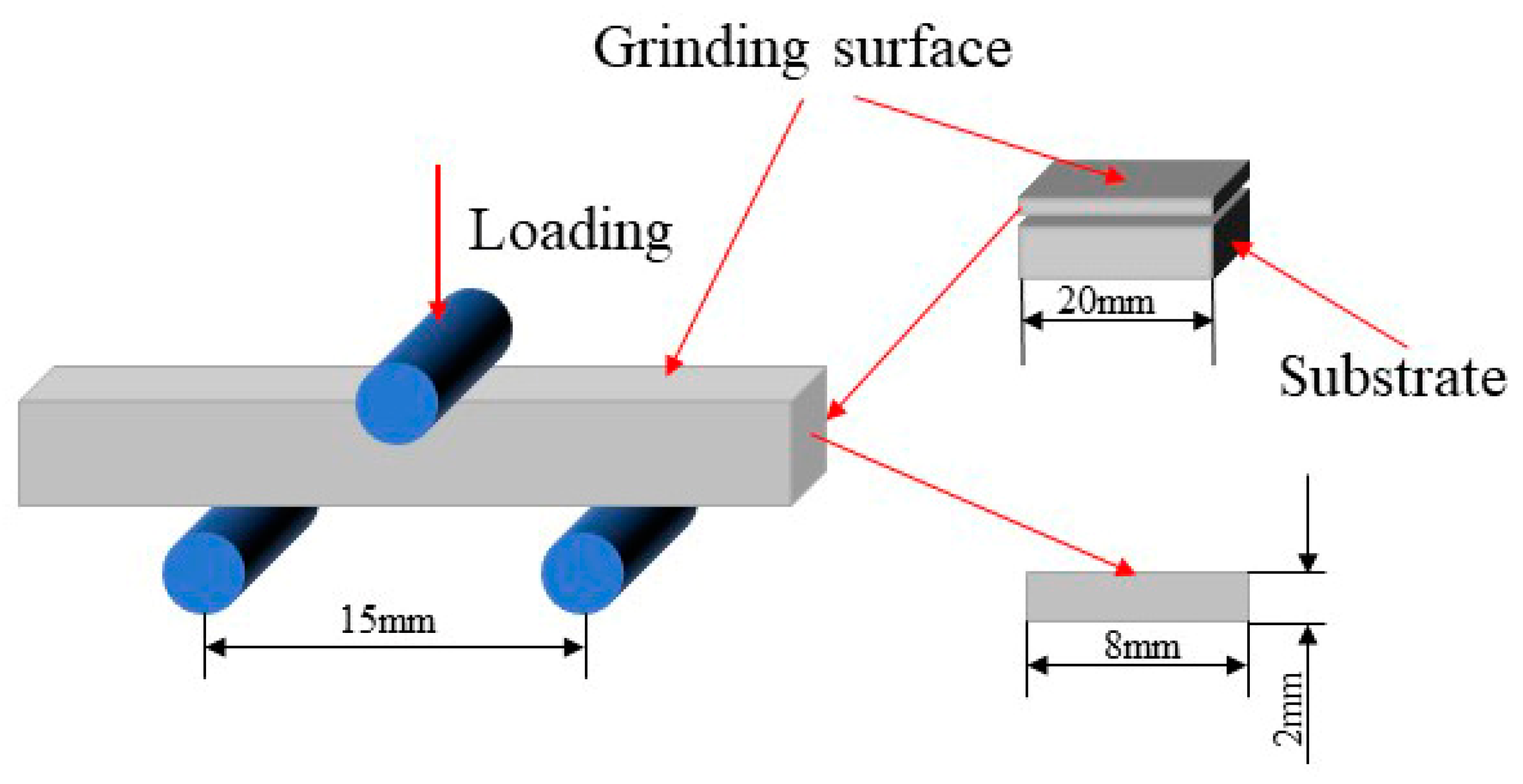
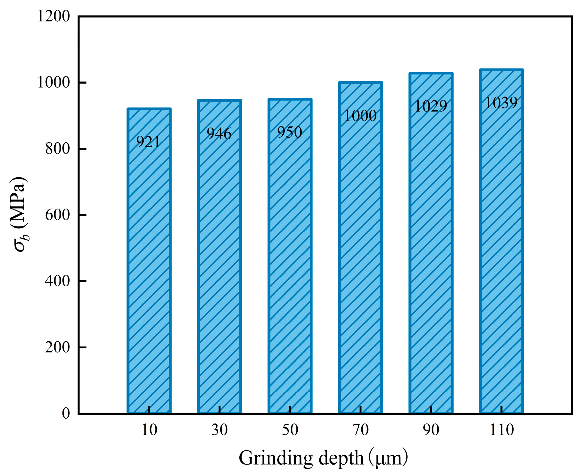
3.5. Three-Point Bending Test
3.6. Microhardness
4. Conclusions
- (1)
- During the grinding process, both the HEA binder phase and the WC are simultaneously removed, undergoing a transition from ductile removal to brittle removal, with brittle removal being predominant.
- (2)
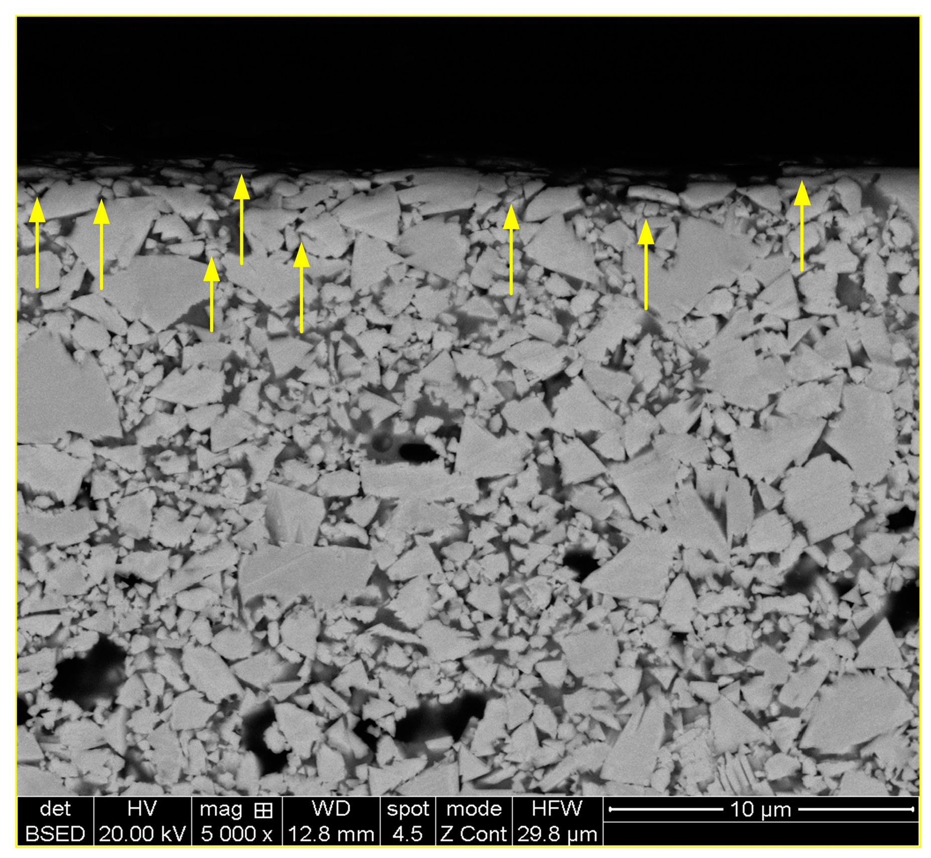
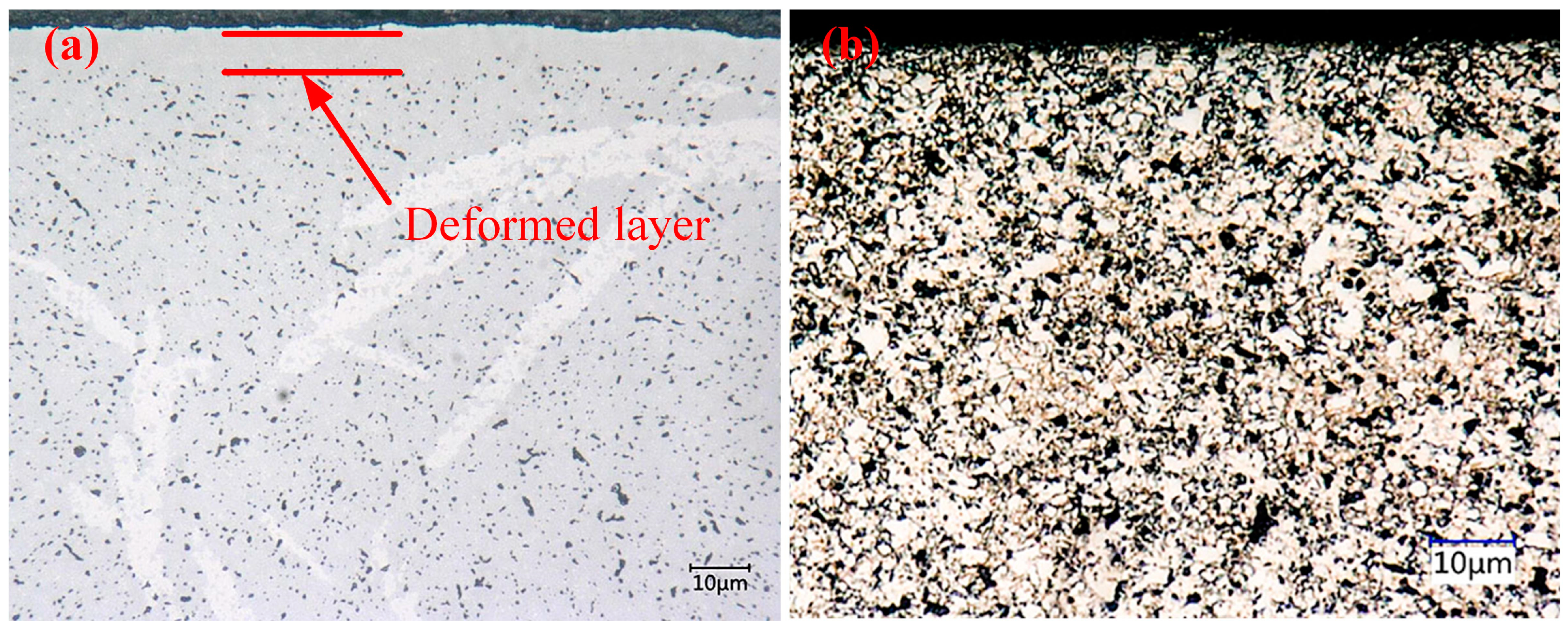
- A subsurface deformed layer is found, characterized primarily by refined WC grains.
- (3)
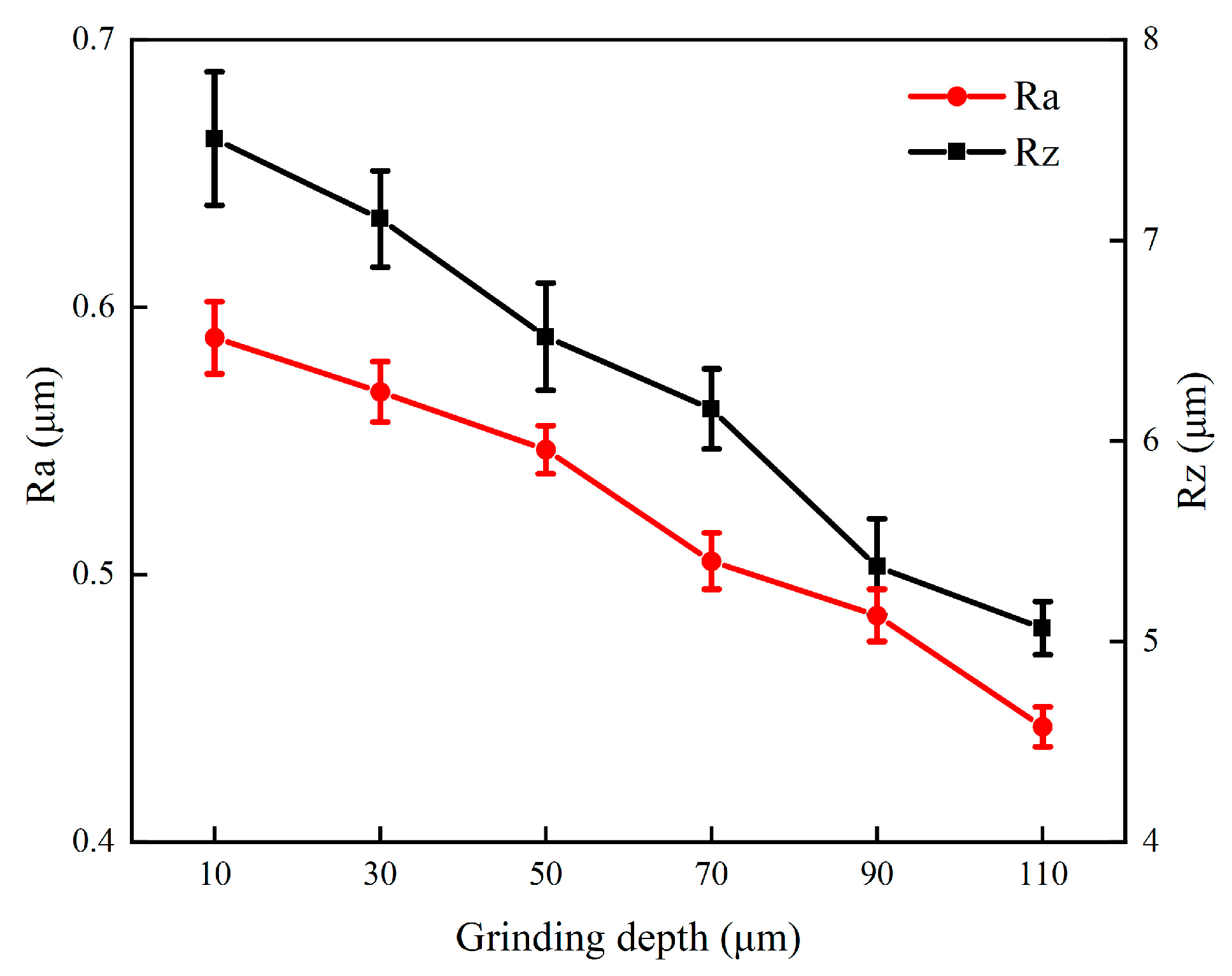
- Surface roughness serves as a direct reflection of surface morphology. It decreases with an increase in grinding depth. A larger depth of grind is an effective machining parameter for achieving high surface quality, as it increases the contact arc length, resulting in a higher number of abrasive grains participating in the cutting process and consequently increasing the material removal rate.
- (4)
- Grinding introduces high compressive stresses onto the surface, with a maximum compressive stress of 1795 MPa. The enhancement of bending strength relies on residual compressive stresses.
- (5)
- Grinding induces surface work hardening, with a hardening layer depth of approximately 180 μm. The degree of work hardening on the ground surface increases with larger depths of cut, reaching a maximum of 113.1%.
Author Contributions
Funding
Data Availability Statement
Conflicts of Interest
References
- Yang, Y.; Zhang, C.; Wang, D.; Nie, L.; Wellmann, D.; Tian, Y. Additive manufacturing of WC-Co hardmetals: A review. Int. J. Adv. Manuf. Technol. 2020, 108, 1653–1673. [Google Scholar] [CrossRef]
- Sun, I.; Zhao, J.; Huang, Z.; Yan, K.; Shen, X.; Xing, J.; Gao, Y.; Jian, Y.; Yang, H.; Li, B. A Review on Binderless Tungsten Carbide: Development and Application. Nano-Micro Lett. 2020, 12, 1–37. [Google Scholar] [CrossRef] [PubMed]
- García, J.; Collado Ciprés, V.; Blomqvist, A.; Kaplan, B. Cemented carbide microstructures: A review. Int. J. Refract. Met. Hard Mater. 2019, 80, 40–68. [Google Scholar] [CrossRef]
- Yu, P.F.; Zhang, L.J.; Cheng, H.; Zhang, H.; Ma, M.Z.; Li, Y.C.; Li, G.; Liaw, P.K.; Liu, R.P. The high-entropy alloys with high hardness and soft magnetic property prepared by mechanical alloying and high-pressure sintering. Intermetallics 2016, 70, 82–87. [Google Scholar] [CrossRef]
- Juan, C.; Hsu, C.; Tsai, C.; Wang, W.; Sheu, T.; Yeh, J.; Chen, S. On microstructure and mechanical performance of AlCoCrFeMo0.5Nix high-entropy alloys. Intermetallics 2013, 32, 401–407. [Google Scholar] [CrossRef]
- Kim, Y.; Joo, Y.; Kim, H.S.; Lee, K. High temperature oxidation behavior of Cr-Mn-Fe-Co-Ni high entropy alloy. Intermetallics 2018, 98, 45–53. [Google Scholar] [CrossRef]
- Chuang, M.; Tsai, M.; Wang, W.; Lin, S.; Yeh, J. Microstructure and wear behavior of AlxCo1.5CrFeNi1.5Tiy high-entropy alloys. Acta Mater. 2011, 59, 6308–6317. [Google Scholar] [CrossRef]
- Chen, C.; Yang, C.; Chai, H.; Yeh, J.; Chau, J.L.H. Novel cermet material of WC/multi-element alloy. Int. J. Refract. Met. Hard Mater. 2014, 43, 200–204. [Google Scholar] [CrossRef]
- Zhou, P.; Xiao, D.; Yuan, T. Comparison between ultrafine-grained WC—Co and WC—HEA-cemented carbides. Powder Metall. 2017, 60, 1–6. [Google Scholar] [CrossRef]
- Byrne, G.; Dornfeld, D.; Denkena, B.; Denkena, B. Advancing Cutting Technology. CIRP Ann. 2003, 52, 483–507. [Google Scholar] [CrossRef]
- Hegeman, J.B.J.W.; De Hosson, J.T.M.; De With, G. Grinding of WC–Co hardmetals. Wear 2001, 248, 187–196. [Google Scholar] [CrossRef]
- Zhu, Y.; Zhang, Q.; Zhao, Q.; To, S. The material removal and the nanometric surface characteristics formation mechanism of TiC/Ni cermet in ultra-precision grinding. Int. J. Refract. Met. Hard Mater. 2021, 96, 105494. [Google Scholar] [CrossRef]
- Wei, C.; He, C.; Chen, G.; Sun, Y.; Ren, C. Material removal mechanism and corresponding models in the grinding process: A critical review. J. Manuf. Process. 2023, 103, 354–392. [Google Scholar] [CrossRef]
- Klocke, F.; Wirtz, C.; Mueller, S.; Mattfeld, P. Analysis of the Material Behavior of Cemented Carbides (WC-Co) in Grinding by Single Grain Cutting Tests. Procedia Cirp. 2016, 46, 209–213. [Google Scholar] [CrossRef]
- Wirtz, C.; Mueller, S.; Mattfeld, P.; Klocke, F. A Discussion on Material Removal Mechanisms in Grinding of Cemented Carbides. J. Manuf. Sci. Eng. 2017, 139, 121002. [Google Scholar] [CrossRef]
- Mueller, S.; Wirtz, C.; Trauth, D.; Mattfeld, P.; Klocke, F. Material removal mechanisms in grinding of two-phase brittle materials. Int. J. Adv. Manuf. Technol. 2018, 95, 287–298. [Google Scholar] [CrossRef]
- Huang, H.; Li, X.; Mu, D.; Lawn, B.R. Science and art of ductile grinding of brittle solids. Int. J. Mach. Tools Manuf. 2021, 161, 103675. [Google Scholar] [CrossRef]
- Yang, J.; Roa, J.J.; Schwind, M.; Odén, M.; Johansson-Jõesaar, M.P.; Llanes, L. Grinding-induced metallurgical alterations in the binder phase of WC-Co cemented carbides. Mater. Charact. 2017, 134, 302–310. [Google Scholar] [CrossRef]
- Yang, J.; Odén, M.; Johansson-Jõesaar, M.P.; Llanes, L. Grinding Effects on Surface Integrity and Mechanical Strength of WC-Co Cemented Carbides. Procedia Cirp. 2014, 13, 257–263. [Google Scholar] [CrossRef]
- Yin, L.; Spowage, A.C.; Ramesh, K.; Huang, H.; Pickering, J.P.; Vancoille, E.Y.J. Influence of microstructure on ultraprecision grinding of cemented carbides. Int. J. Mach. Tools Manuf. 2004, 44, 533–543. [Google Scholar] [CrossRef]
- Zhang, Q.; To, S.; Zhao, Q.; Guo, B.; Wu, M. Effects of binder addition on the surface generation mechanism of WC/Co during high spindle speed grinding (HSSG). Int. J. Refract. Met. Hard Mater. 2016, 59, 32–39. [Google Scholar] [CrossRef]
- Liang, F.; Du, J.; Su, G.; Zhang, P.; Zhang, C. Investigating the effect of Al, Mo or Mn addition to CoCrFeNi entropy alloys on the interface binding properties of WC/HEA cemented carbides. Mater. Today Commun. 2023, 35, 105891. [Google Scholar] [CrossRef]
- Luo, W.; Liu, Y.; Shen, J. Effects of binders on the microstructures and mechanical properties of ultrafine WC-10%AlxCoCrCuFeNi composites by spark plasma sintering. J. Alloys Compd. 2019, 791, 540–549. [Google Scholar] [CrossRef]
- Ghosh, N.; Ravi, Y.B.; Patra, A.; Mukhopadhyay, S.; Paul, S.; Mohanty, A.R.; Chattopadhyay, A.B. Estimation of tool wear during CNC milling using neural network-based sensor fusion. Mech. Syst. Signal Pr. 2007, 21, 466–479. [Google Scholar] [CrossRef]
- Luo, Q.; Jones, A.H. High-precision determination of residual stress of polycrystalline coatings using optimised XRD-sin2ψ technique. Surf. Coat. Technol. 2010, 205, 1403–1408. [Google Scholar] [CrossRef]
- Li, A.; Zhao, J.; Wang, D.; Gao, X.; Tang, H. Three-point bending fatigue behavior of WC–Co cemented carbides. Mater. Design. 2013, 45, 271–278. [Google Scholar] [CrossRef]
- Zhou, K.; Ding, H.H.; Wang, W.J.; Wang, R.X.; Guo, J.; Liu, Q.Y. Influence of grinding pressure on removal behaviours of rail material. Tribol. Int. 2019, 134, 417–426. [Google Scholar] [CrossRef]
- Zhang, Y.; Li, C.; Ji, H.; Yang, X.; Yang, M.; Jia, D.; Zhang, X.; Li, R.; Wang, J. Analysis of grinding mechanics and improved predictive force model based on material-removal and plastic-stacking mechanisms. Int. J. Mach. Tools Manuf. 2017, 122, 81–97. [Google Scholar] [CrossRef]
- Guezmil, M.; Bensalah, W.; Mezlini, S. Tribological behavior of UHMWPE against TiAl6V4 and CoCr28Mo alloys under dry and lubricated conditions. J. Mech. Behav. Biomed. 2016, 63, 375–385. [Google Scholar] [CrossRef]
- Krawitz, A.; Drake, E. Residual stresses in cemented carbides—An overview. Int. J. Refract. Met. Hard Mater. 2015, 49, 27–35. [Google Scholar] [CrossRef]
- Elsheikh, A.H.; Shanmugan, S.; Muthuramalingam, T.; Thakur, A.K.; Essa, F.A.; Ibrahim, A.M.M.; Mosleh, A.O. A comprehensive review on residual stresses in turning. Adv. Manuf. 2022, 10, 287–312. [Google Scholar] [CrossRef]
- Torres, Y.; Sarin, V.K.; Anglada, M.; Llanes, L. Loading mode effects on the fracture toughness and fatigue crack growth resistance of WC–Co cemented carbides. Scripta Mater. 2005, 52, 1087–1091. [Google Scholar] [CrossRef]
- Wang, J.; Bai, X.; Shen, X.; Liu, X.; Wang, B. Effect of micro-texture on substrate surface on adhesion performance of electroless Ni P coating. J. Manuf. Process. 2022, 74, 296–307. [Google Scholar] [CrossRef]
- Torres, Y.; Anglada, M.; Llanes, L. Fatigue mechanics of WC–Co cemented carbides. Int. J. Refract. Met. Hard Mater. 2001, 19, 341–348. [Google Scholar] [CrossRef]
- Heinzel, C.; Bleil, N. The Use of the Size Effect in Grinding for Work-hardening. CIRP Ann. 2007, 56, 327–330. [Google Scholar] [CrossRef]


| Material | Relative Density (%) | Hardness (HV) | KIC (MPa∙m1/2) | TRS(MPa) |
|---|---|---|---|---|
| WC-HEA | 92.3 | 1537.8 | 8.7 | 890 |
| Grinding Wheel Speed νs. (m/s) | Workpiece Feed Speed νw (m/min) | Grinding Depth ap (μm) |
|---|---|---|
| 30.14 | 6 | 10, 30, 50, 70, 90, 110 |
| Grinding Depth (μm) | Angle ψ (º) |
|---|---|
| 10 | 0, 9, 18, 27, 36, 45 |
| 30 | 0, 9, 18, 27, 36, 45 |
| 50 | 0, 9, 18, 27, 36, 45 |
| 70 | 0, 9, 18, 27, 36, 45 |
| 90 | 0, 9, 18, 27, 36, 45 |
| 110 | 0, 9, 18, 27, 36, 45 |
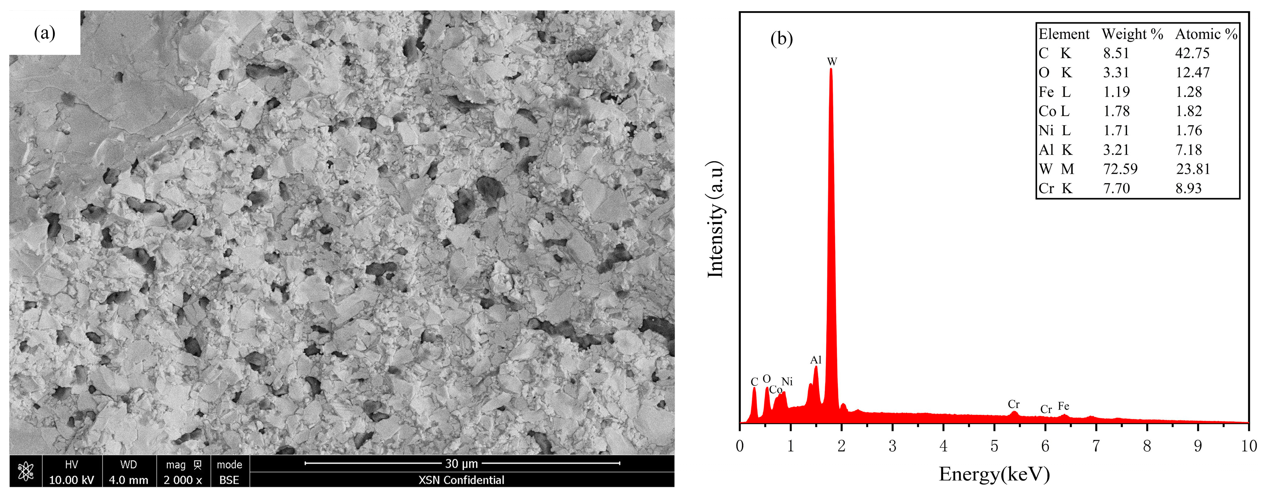
| Element | Fracture (wt.%) | ap = 10 μm (wt.%) | ap = 30 μm (wt.%) | ap = 50 μm (wt.%) | ap = 110 μm (wt.%) |
|---|---|---|---|---|---|
| C K | 8.51 | 7.30 | 6.99 | 8.45 | 7.04 |
| O K | 3.31 | 2.41 | 2.56 | 2.36 | 2.14 |
| Fe L | 1.19 | 0.81 | 0.70 | 0.72 | 0.77 |
| Co L | 1.78 | 1.31 | 1.32 | 1.33 | 1.49 |
| Ni L | 1.71 | 1.35 | 1.47 | 1.46 | 1.55 |
| Al K | 3.21 | 1.39 | 2.08 | 1.69 | 1.55 |
| W M | 72.59 | 78.71 | 78.56 | 78.62 | 80.27 |
| Cr K | 7.7 | 6.72 | 6.32 | 5.37 | 5.19 |
Disclaimer/Publisher’s Note: The statements, opinions and data contained in all publications are solely those of the individual author(s) and contributor(s) and not of MDPI and/or the editor(s). MDPI and/or the editor(s) disclaim responsibility for any injury to people or property resulting from any ideas, methods, instructions or products referred to in the content. |
© 2024 by the authors. Licensee MDPI, Basel, Switzerland. This article is an open access article distributed under the terms and conditions of the Creative Commons Attribution (CC BY) license (https://creativecommons.org/licenses/by/4.0/).
Share and Cite
Yin, Y.; Du, J.; Sun, Y.; Xia, Y.; Zhang, P.; Su, G. Investigation of the Machined Surface Integrity of WC-High-Entropy Alloy Cemented Carbide. Metals 2024, 14, 419. https://doi.org/10.3390/met14040419
Yin Y, Du J, Sun Y, Xia Y, Zhang P, Su G. Investigation of the Machined Surface Integrity of WC-High-Entropy Alloy Cemented Carbide. Metals. 2024; 14(4):419. https://doi.org/10.3390/met14040419
Chicago/Turabian StyleYin, Yandong, Jin Du, Yujing Sun, Yan Xia, Peirong Zhang, and Guosheng Su. 2024. "Investigation of the Machined Surface Integrity of WC-High-Entropy Alloy Cemented Carbide" Metals 14, no. 4: 419. https://doi.org/10.3390/met14040419
APA StyleYin, Y., Du, J., Sun, Y., Xia, Y., Zhang, P., & Su, G. (2024). Investigation of the Machined Surface Integrity of WC-High-Entropy Alloy Cemented Carbide. Metals, 14(4), 419. https://doi.org/10.3390/met14040419