Abstract
The potential use of carbon steel in CO2-saturated brine is studied for its potential use in heat exchangers in geothermal applications. A dedicated setup, including a double-pipe heat exchanger, is developed to study the relation between corrosion and the thermohydraulic behavior inside heat exchangers. Hot brine flows inside the inner carbon steel tube, thus corroding the inner surface of this tube. The thermohydraulic behavior of the heat exchanger, i.e., the pressure drop over the pipe and the heat transfer rate through the pipe, are continuously monitored. On the other hand, weight-loss experiments and microscopic analyses are performed on samples that are periodically removed from the setup. The corrosion rate is studied as a function of temperature, i.e., the entrance vs. the exit of the heat-exchanging section, and flow. Therefore, an experiment with static brine and a uniform temperature is used as a reference. The corrosion rate is generally higher in dynamic compared to static conditions. Furthermore, the corrosion rate increases with increasing temperature in dynamic conditions, whereas it decreases with increasing temperature in static conditions. These observations might be explained by the different corrosion products that formed. The corrosion products have no significant effect on the pressure drop over the pipe, but clear fluctuations in the heat transfer coefficient are observed. The origin of these fluctuations should be further studied before the observed heat transfer coefficient can be used as a measure for corrosion.
1. Introduction
Corrosion is a well-recognized problem but is still not resolved. In a study by NACE, it was calculated that the annual global cost of corrosion amounts to USD 2.5 trillion [1], of which EUR 500 billion is for the European region alone [2]. According to other sources [3,4,5], the total cost of corrosion for the electrical power industry was USD 15.4 billion in the U.S. in 1998, where the corrosion of heat exchangers takes up 5.55% or USD 855 million annually. In general, it can be stated that the costs due to corrosion account for 3–5% of the gross domestic product of a country [6,7]. From an economic point of view, an improved understanding of corrosion mechanisms is highly desired to reduce the associated costs.
Besides the economic benefits, corrosion also has an ecological impact. Corrosion results in both the pollution of the environment with heavy metals [8,9] and metal losses which can no longer be recycled [10,11]. The latter results in an increased need for primary metal production, which produces high amounts of CO2 and is an energy-intensive process [12,13,14,15]. Consequently, the required power generation also has a significant ecological impact. Geothermal energy is a promising source for green power generation, but the installations used are often prone to corrosion. In other words, the study of corrosion in geothermal power plants is interesting both from an economic and ecological point of view. Limiting corrosion has both a direct effect, i.e., limiting the need for the replacement of the metals within an installation, and an indirect effect, i.e., enabling the use of the benefits of geothermal energy.
In industry, heat exchangers are often exposed to corroding fluids [16,17,18]. Brine in geothermal applications is the specific case studied in this work. Consequently, heat exchangers are regularly subject to corrosion, which can be both uniform [19] and localized corrosion [20,21]. Stainless steels or other passivating metals usually show a limited uniform corrosion rate. However, they are often more prone to localized forms of corrosion, e.g., pitting corrosion. One pit piercing the heat transfer surface is sufficient to cause leakage between the two fluids in a heat exchanger, resulting in a loss of functionality. This local corrosion is virtually impossible to monitor in situ. Hence, metals showing (faster) uniform corrosion without localized corrosion are sometimes preferred over passivating metals. Therefore, carbon steel is an interesting construction material for heat exchangers, as it is a cheap metal with high metallurgical adaptability that shows (limited) uniform corrosion [22]. However, it is unknown whether this corrosion process might affect thermohydraulic behavior and vice versa. For example, corrosion products could affect the heat and mass flow in the heat exchanger, while, on the other hand, the fluid flow could result in the continuous removal of protective corrosion products, affecting the corrosion rate. The goal of this study is to answer this remaining question, as, to the best of our knowledge, no other pilot-scale study combining both corrosion and the thermohydraulic behavior inside a heat exchanger exists.
Moreover, from an investigation with static brine [23], it was observed that carbon steel could form a protective iron carbonate layer, decreasing the corrosion rate with time. However, it is unknown whether this carbonate layer affects the thermohydraulic behavior of the heat exchanger and vice versa. Therefore, the scope of this study is threefold:
- To determine the influence of corrosion on the performance of the heat exchanger;
- To determine the influence of flow on the corrosion process, i.e., static vs. dynamic conditions;
- To evaluate different possible corrosion monitoring approaches (e.g., pressure drop, heat transfer coefficient).
2. Materials and Methods
2.1. Setup Operation
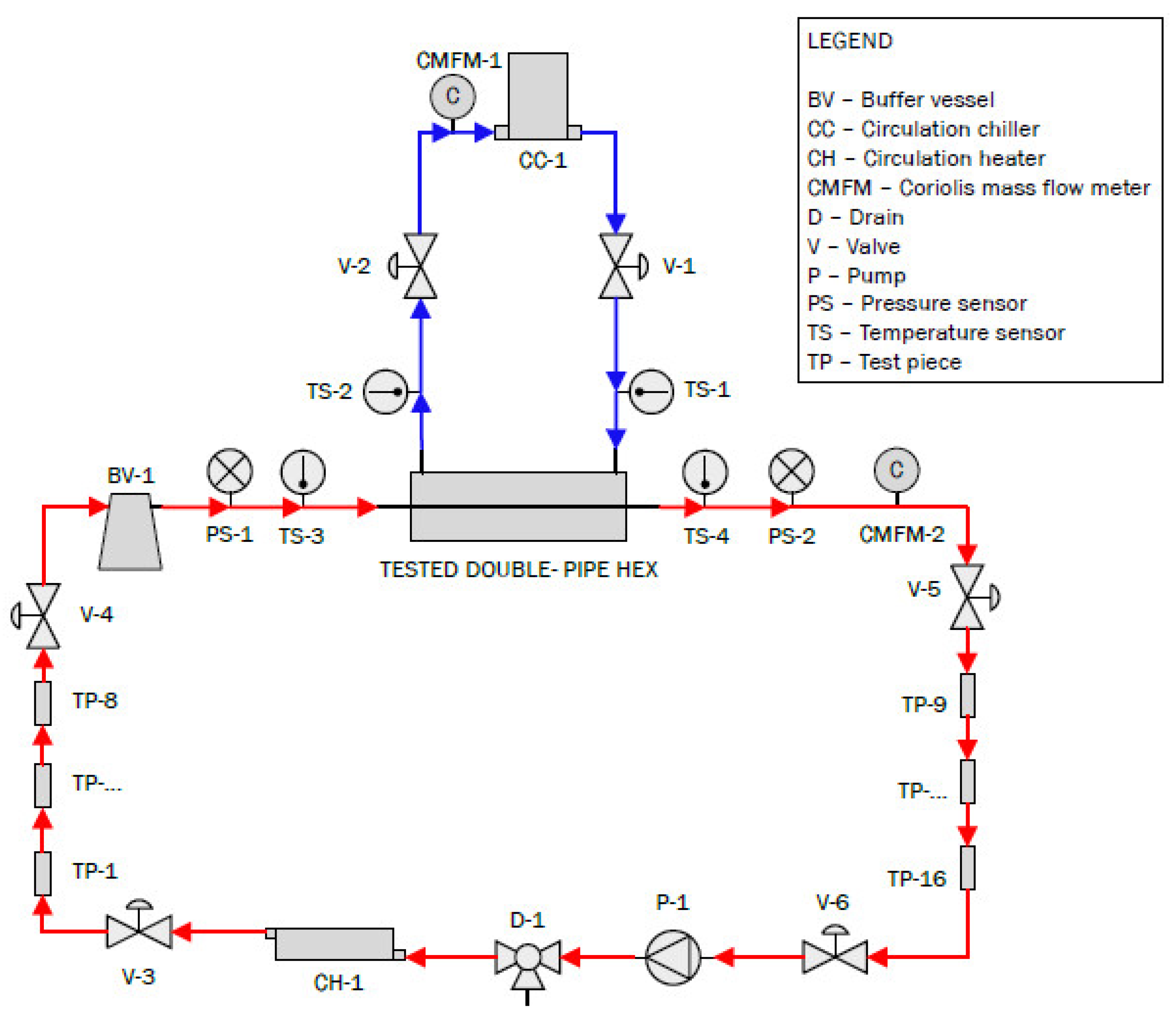
The goal of this study was to investigate the relation between corrosion and the thermohydraulic behavior of heat exchangers. For this purpose, a dedicated setup was built, including a double-pipe heat exchanger. A schematic overview of the experimental setup is presented in Figure 1. Hot artificial brine flowed inside the inner tube (indicated in red; artificial brine composition presented in Table 1), whereas cooling liquid flowed in the annulus between the inner tube and the outer tube (a 50% water–ethylene glycol mixture, indicated in blue). The brine was purged with CO2 prior to the experiments to remove any oxygen present and to mimic the high CO2 content in pressurized geothermal brine, after which the setup was sealed.
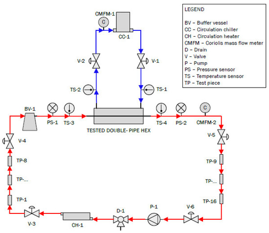
Figure 1.
Schematic representation of the developed experimental setup (hot brine flows in red cycle, 50% water–ethylene glycol mixture flows in blue cycle).

Table 1.
Composition of the artificial brine.
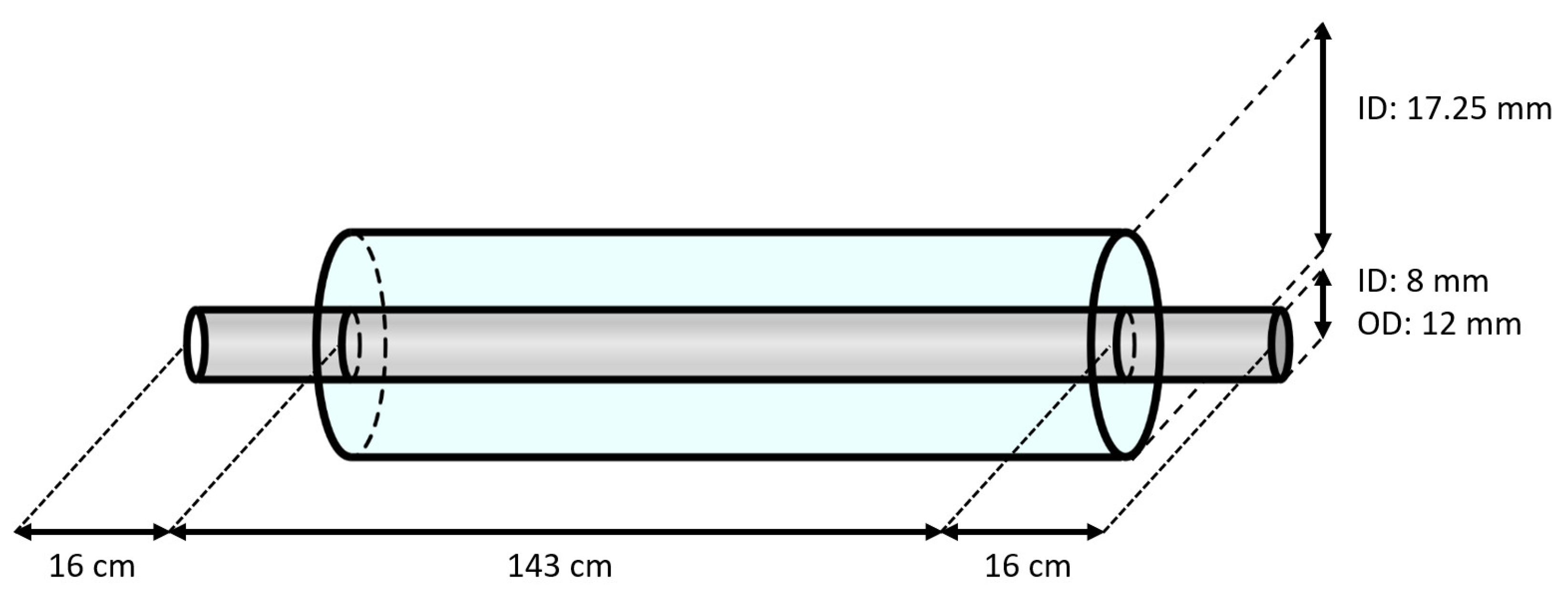
A schematic overview of the double-piped section is represented in Figure 2. The inner tube of the heat exchanger was made of carbon steel (type E235+C (see Table 2), according to standard EN 10305-4 [24]) with an inner diameter of 8 mm and a wall thickness of 2 mm. This tube had a length of 1.75 m. Replaceable samples from this tube with a length of 6 cm, located before (i.e., the hot section) and after (i.e., the cold section) the heat exchanger, were used for the mass-loss measurements. The outer tube of the heat exchanger was made of copper, with an inside diameter of 17.25 mm. To be able to mount the inner tube and inspect its outer surface, the copper tube had a length of only 1.43 m, resulting in an exposed part of the inner tube of 16 cm on both sides of the heat exchanger. The entire test section was insulated with PE foam to limit the heat losses to the environment. Lastly, in order to avoid galvanic corrosion between the test section and other components in the brine loop, all connecting tubes were made of polymers.
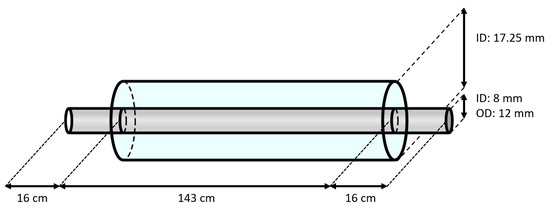
Figure 2.
Schematic overview of the double-piped heat exchanger (not to scale).

Table 2.
Composition of the used E235+C steel.
Due to the brine, the inner surface of the inner tube exhibited corrosion. Corrosion products typically have a lower thermal conductivity than the base metal, possibly limiting heat transfer and reducing efficiency [25,26,27]. Also, the resulting increased surface roughness might affect heat transfer [28,29], but could also alter the pressure drop over the tube [29]. Since limited information about the occurring processes can be found in the literature, there is still the question of how corrosion evolves in heat exchangers and what effect this has on their performance. Therefore, the setup was operated for 14 months under the specified conditions to allow the tube to corrode.
The scope of this study was to evaluate the effect of corrosion on the thermohydraulic performance of the heat exchanger. Therefore, several sensors were installed in the setup to monitor the heat exchanger’s performance. For measuring temperatures, Pt-100 temperature sensors were used. Four of these sensors were installed in the setup (TS-1 to TS-4). They were placed before and after the heat exchanger on both the brine side and the coolant side. Additionally, pressure sensors (PS-1 and PS-2) were mounted before and after the heat exchanger in the hot circuit. Finally, two Coriolis mass flow meters (CMFM-1 and CMFM-2) were used to determine the flow rates. One was installed in the brine circuit, while the other was installed in the coolant circuit. Coriolis mass flow meters were selected because they can determine the mass flow rate without prior knowledge of the density of the fluid and have high accuracy. All components of the different sensors that came into direct contact with the brine were either polymers or stainless steel. The pressure drop, temperature, and flow rate were continuously monitored in situ to assess the thermohydraulic behavior, i.e., pressure drop and heat transfer coefficient, whereas weight-loss experiments on the replaceable test pieces were performed post-exposure to measure the corrosion behavior of the inner tube.
2.2. Sample Analysis
Weight-loss experiments and microscopic analyses (i.e., SEM and EDX) were performed on test samples that were periodically removed from the setup. The procedure to find the weight after exposure was in accordance with the ASTM G1 standard. From the weight loss obtained, the corrosion rate was determined using Equation (1). Here, CR is the corrosion rate (mm/year), K is a constant ((mm·s)/(cm·year)), W is the measured weight difference (g), A is the surface area of the sample (cm2), T is the duration of the experiment (s), and D is the density of the sample (g/cm³).
In the microscopic analysis using a FEG SEM JSM-7600F (JEOL, Tokyo, Japan), both the inner surface of the tube and a cross section of the tube wall were studied. The inner surface was studied without any pretreatment, whereas for the cross sections, the samples were cut, embedded in Bakelite, ground using SiC grinding paper starting at #80 and going to #2000, and mechanically polished.
The flow rate of both the coolant and the brine was varied in these experiments, and the effect of the brine temperature was studied at different locations near the heat exchanger (the brine entered the heat exchanger at approximately 80 °C and left at about 60 °C). This temperature difference could affect the characteristics of the environmental degradation of the material. Moreover, the fluid flow could wear off possible corrosion products, impacting the formation of a protective layer. Therefore, an experiment with static brine at a uniform temperature, which has already been presented in an earlier publication [23], was used as a reference for the results obtained in this work. In these static experiments, pressurization was obtained by the temperature increase and the accompanying evaporation.
3. Results and Discussions
First, the corrosion rate found via weight-loss experiments as a function of temperature and flow is presented. The results in static conditions, published in our earlier work [23], are briefly summarized here for the convenience of the reader. Next, the observed trends are explained using the results from the microscopic analysis. Finally, these obtained results are compared with the observations for the pressure drop and heat transfer coefficient to assess the possible use of the thermohydraulic behavior as a measure of corrosion.
3.1. Weight-Loss Experiments
The corrosion rate as determined via the weight-loss analysis is presented in Figure 3. Note that these results represent the average corrosion rate over the reported time period and not the instantaneous corrosion rate. Moreover, different samples were used for different exposure times, as the formed corrosion layer was removed during the weight-loss measurement. The latter could explain the big error bars observed in Figure 3b. Nonetheless, a clear trend was still observed. In the static conditions, the corrosion rate clearly decreased with increasing exposure time, which was not observed in the dynamic conditions. Secondly, a local maximum corrosion rate as a function of temperature was observed in the static conditions. The tests in the dynamic conditions were only carried out at two different temperatures for practical reasons; hence, no local maximum could be studied. Nonetheless, it can be seen that the difference between the experiments at 60 °C and 80 °C was much more substantial in the dynamic conditions than in the static conditions. The observation of this local maximum corrosion rate as a function of temperature is further discussed in Section 3.2. Lastly, the corrosion rate during the first 28 days of the experiment was clearly higher in the dynamic conditions. This could have multiple explanations, including the following:
- An increased supply of reactants;
- The continuous erosive removal of the corrosion products;
- The formation of different corrosion products due to the different conditions.
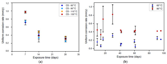
Figure 3.
Average corrosion rate (obtained via weight loss) as a function of exposure time for different temperatures (color legend): (a) static conditions; (b) dynamic conditions.
Figure 3.
Average corrosion rate (obtained via weight loss) as a function of exposure time for different temperatures (color legend): (a) static conditions; (b) dynamic conditions.
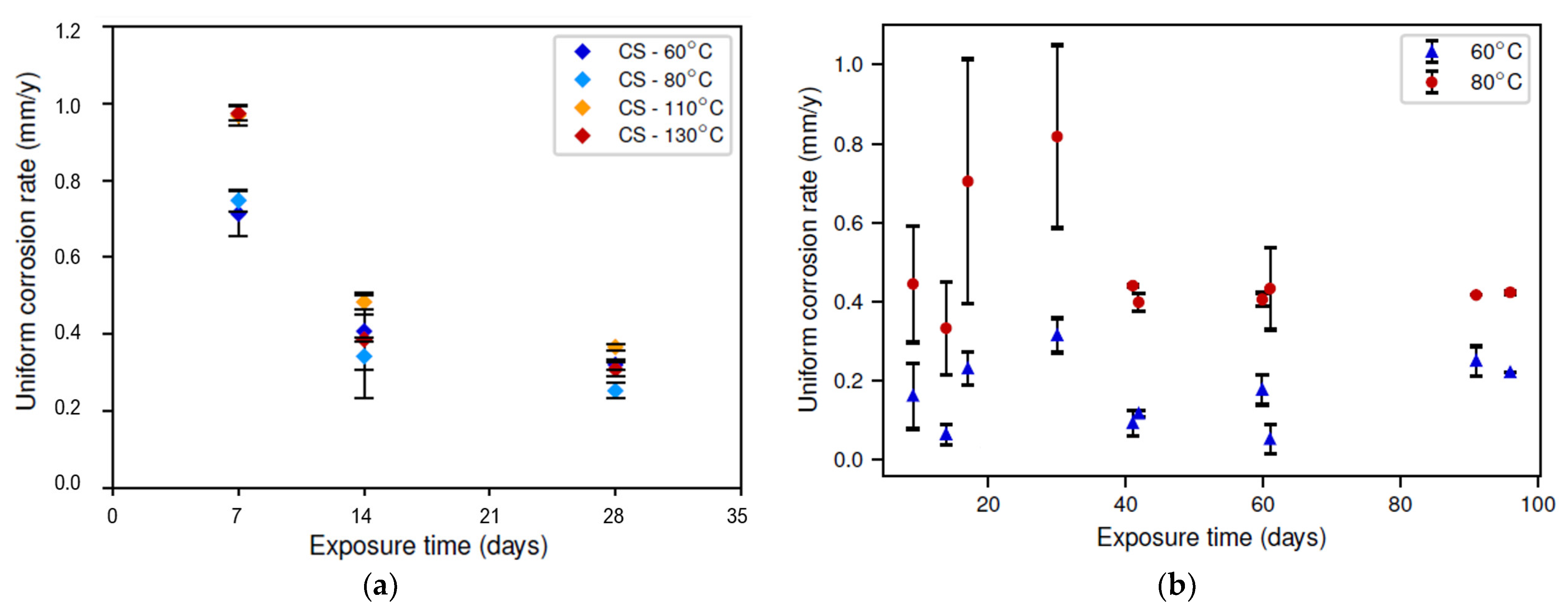
In the dynamic conditions, the initially increasing corrosion rate (up to an exposure time of 28 days) could indicate the removal of an initially present corrosion layer, also removing its protective effect. At the same time, a new corrosion layer started to form, which, after 28 days, resulted in a reducing corrosion rate. This hypothesis is further discussed in Section 3.3.
3.2. Microscopic Analysis
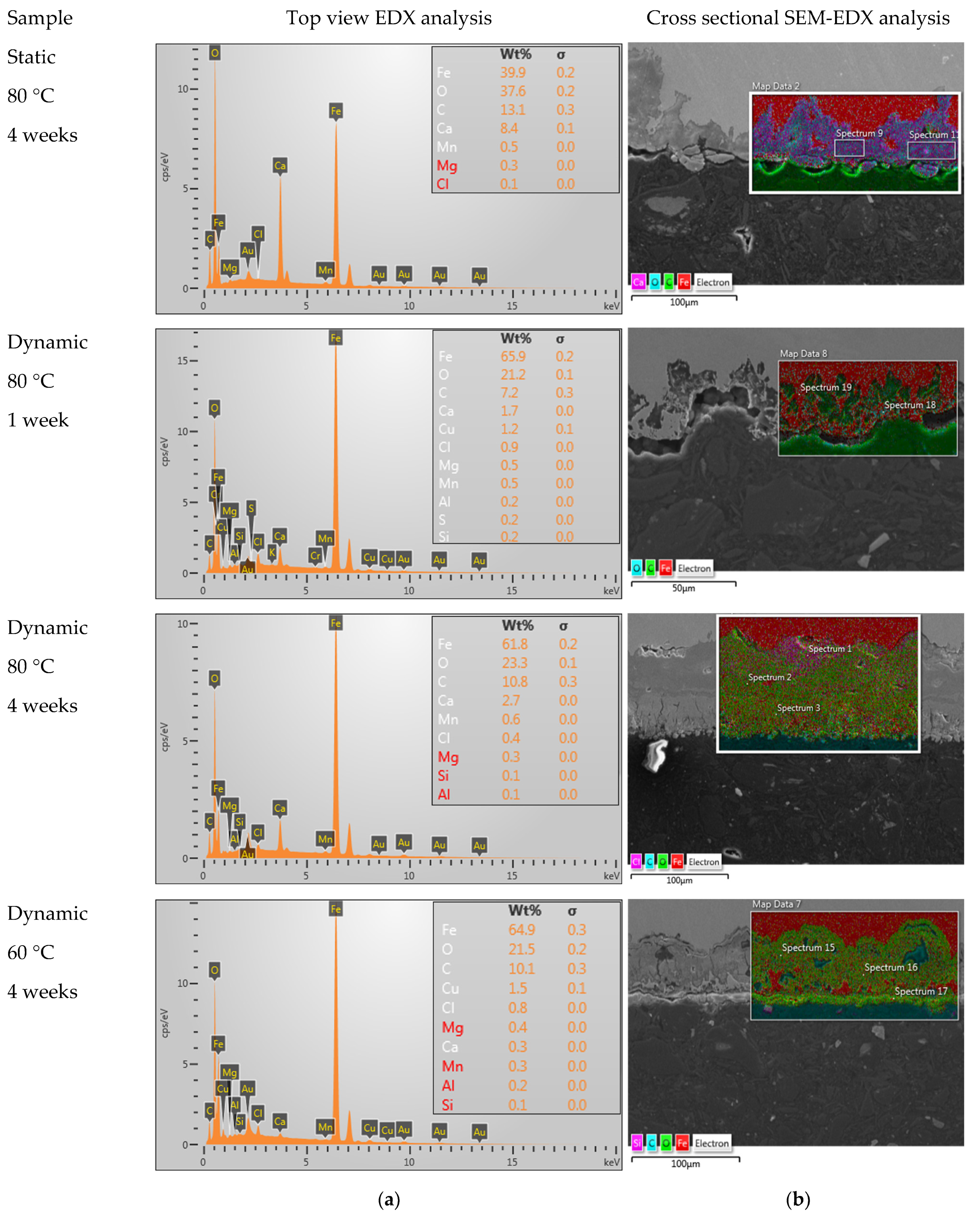
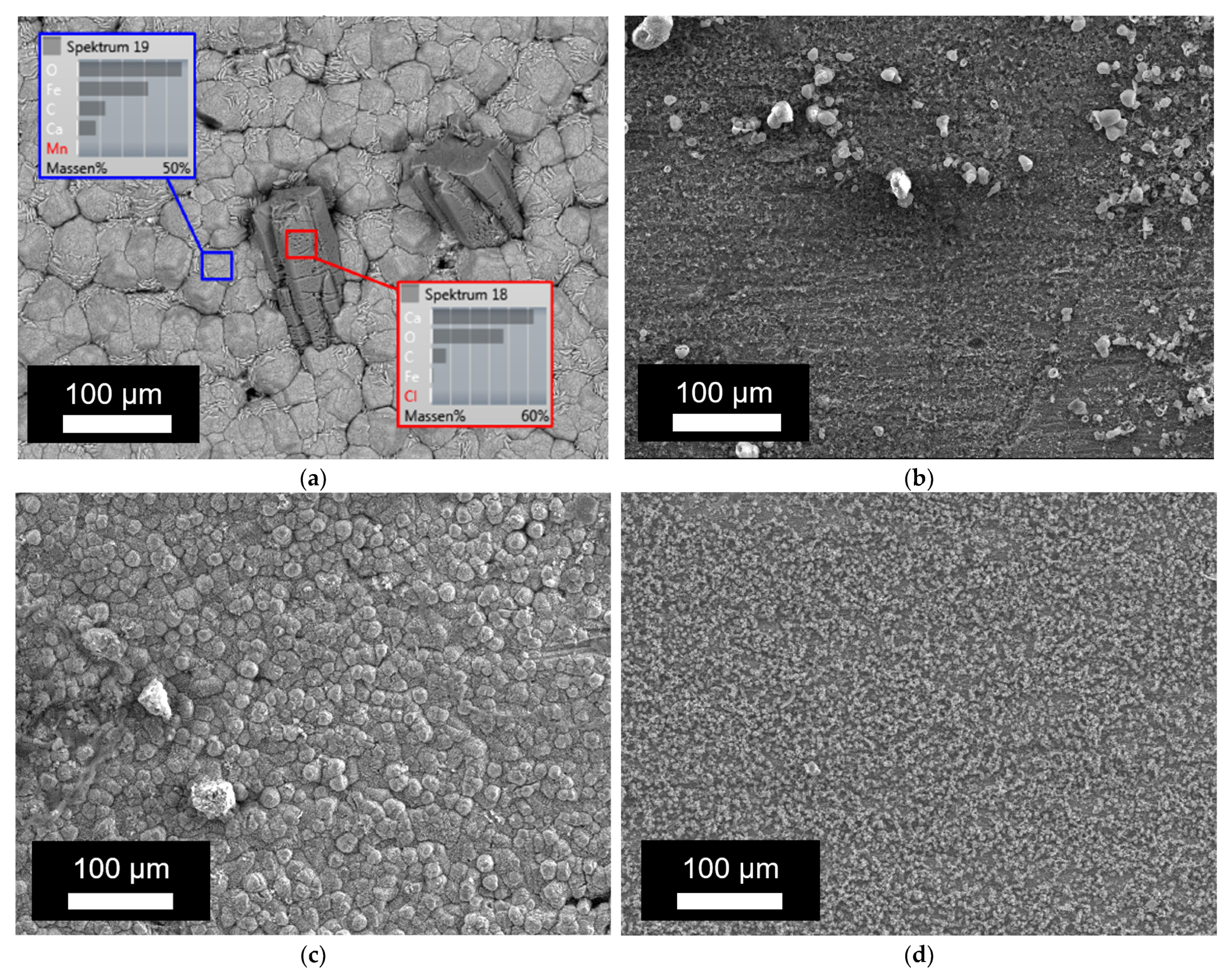
Next, the corrosion products formed on the inside of the tube were studied via SEM-EDX. Figure 4a shows the elemental analysis of the corrosion products observed on the inner surface of the tube, whereas the corrosion depth was studied on the cross section of the tube wall via SEM, as presented in Figure 4b. Additionally, the results with SEM on the bare surface are presented in Figure 5. The results of the EDX and corrosion depth analysis are summarized in Table 3. As a reference, the expected EDX results in the cases of pure FeO, FeCO3, and CaCO3 are also reported in this table. Considering the low values obtained for carbon and the high carbon content in bakelite, the relative amounts of FeO, FeCO3, and CaCO3 present in the corrosion layer were determined while assuming that these were the only present phases and only considering the measured values for Fe, Ca, and O. While both calcium carbonates and iron carbonates were observed under static conditions, the results from EDX showed significantly fewer carbonates (both calcium carbonates and/or iron carbonates) under the dynamic conditions (cf. Figure 5 and Table 3). On the other hand, the observed corrosion depth with SEM increased with increasing temperature, with increasing time, and with increasing flow. Note that the order of corrosion depth obtained via SEM after 4 weeks of exposure was the same as that for the corrosion rate obtained via the weight-loss experiments, as can be seen by comparing Table 3 with Figure 3.
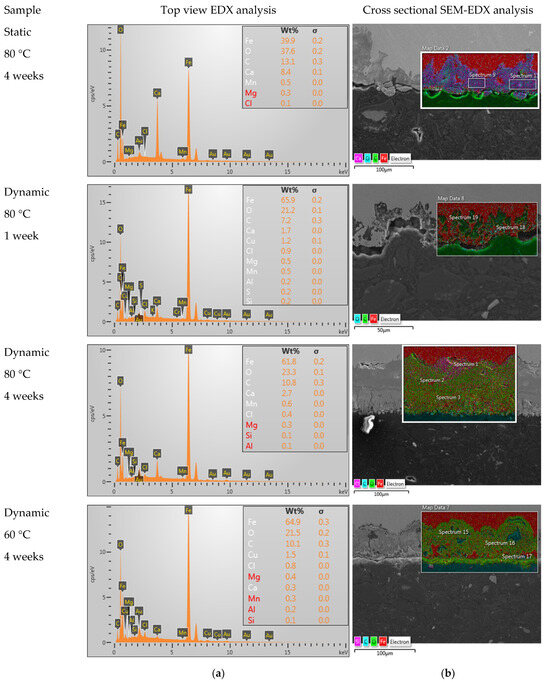
Figure 4.
Results obtained after 4 weeks under static conditions at 80 °C, 1 week in dynamic conditions at 80 °C, 4 weeks in dynamic conditions at 80 °C, and 4 weeks in dynamic conditions at 60 °C via (a) EDX and (b) SEM-EDX.
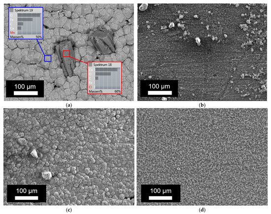
Figure 5.
SEM images of the inside of the tube after exposure at 80 °C: (a) after 1 week in static conditions; (b) after 1 week in dynamic conditions; (c) after 4 weeks in static conditions; and (d) after 4 weeks in dynamic conditions.

Table 3.
Overview of the results obtained via SEM and EDX on samples after 4 weeks, as well as the calculated relative presence of the different phases (the theoretically expected values in cases of pure FeO, FeCO3, and CaCO3 are reported as a reference).
From the above results, it was concluded that dynamic conditions favor oxide precipitation, whereas static conditions favor carbonate precipitation. In the literature, it can be found that carbonate solubility decreases with increasing temperature [30]. Consequently, both the kinetics and the thermodynamic driving force for carbonate precipitation increased with increasing temperature, resulting in a thicker and more stable, i.e., more protective, carbonate layer at higher temperatures. This effect compensated for the increasing corrosion rate with increasing temperature, as depicted by the Arrhenius effect. These two counteracting effects with increasing temperature, i.e., the increasing corrosion rate due to the Arrhenius effect and the decreasing corrosion rate due to the increased protectiveness of the carbonate layer, resulted in a local maximum corrosion rate as a function of temperature in the static conditions. On the other hand, only two different temperatures were tested in the dynamic conditions due to the long duration of the tests, and hence, the local maximum could not be studied. Nonetheless, the bigger effect of temperature in the dynamic conditions as compared to the static conditions could indicate that there is no local maximum corrosion rate with increasing temperature. Moreover, no such local maximum was expected because the solubility of iron oxides is virtually independent of temperature. Further testing in dynamic conditions at multiple different temperatures is required to confirm this hypothesis.
Another interesting feature observed in the dynamic testing was the transient behavior at the beginning of the experiment. This transient behavior could be explained by specific details in the experimental methodology. The setup was filled with artificial brine before the flow was started. Consequently, before the start of the experiment, the samples were in static conditions in contact with the brine, and carbonate layer formation could initiate. Once the flow started, the carbonate layer was no longer stable and was slowly replaced by an oxide layer. Unfortunately, this replacement of the corrosion layer could not be observed via EDX. The initial corrosion layer was too thin, and therefore, the bulk composition would alter the EDX measurement (cf. discussion of Table 3). The removal of a carbonate layer with the formation of an oxide layer has been observed before due to a reaction with oxygen [31]. Hence, it can be assumed that oxygen reactivity increases under dynamic conditions. Apart from thermodynamics, the driving force for the corrosion layer replacement could also be related to the flow, where the carbonate layer might be more prone to erosion than the oxide layer. Further research is required to elaborate on the driving force for the corrosion layer replacement.
3.3. Assessment of New Measures for Corrosion
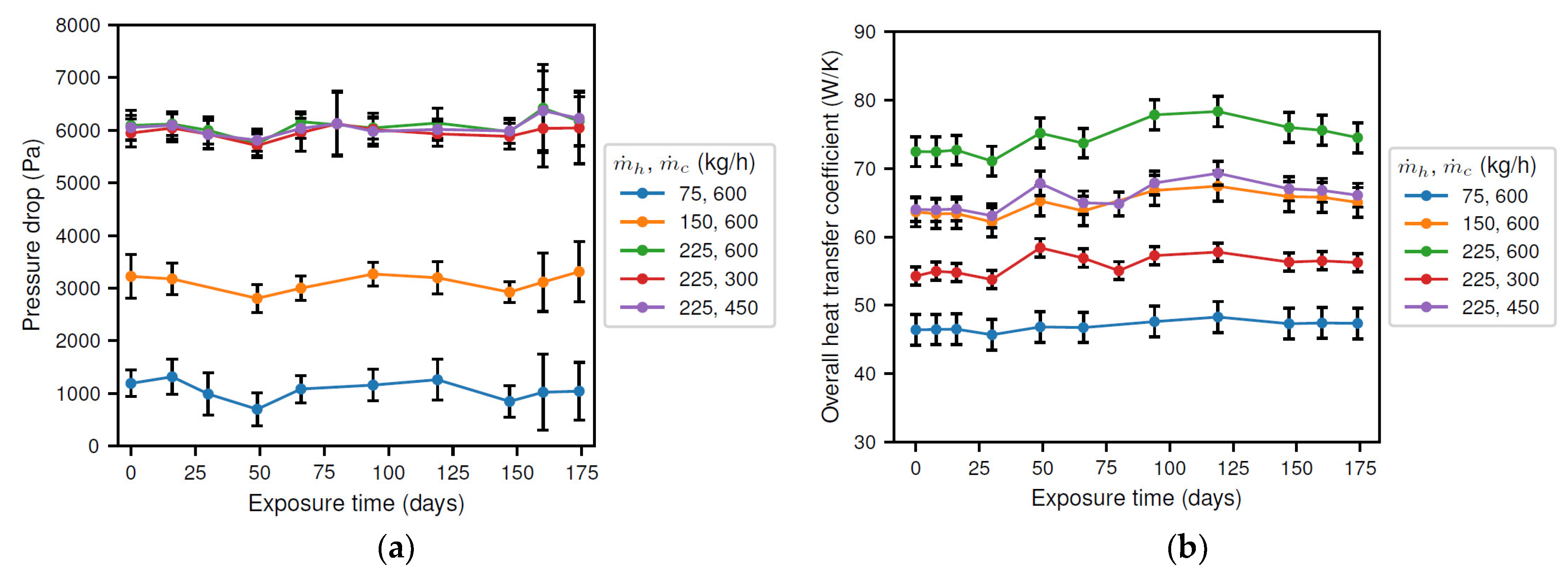
The results for the pressure drop and heat transfer coefficient are presented in Figure 6. From Figure 6a, it is observed that the pressure drop was essentially constant in time and only depended on the brine flow rate. Consequently, it was concluded that the corrosion products had no significant effect on the cross section of the tube. Next, the overall heat transfer coefficient, presented in Figure 6b, also depended on the flow rate of both the brine and the coolant. Moreover, it showed a small variation as a function of exposure time. Initially, an increasing value was found, reaching a maximum of approximately 106% (i.e., 6% increase) of the initial value after about 120 days. Afterwards, the overall heat transfer rate decreased until the end of the experiment, where a similar value as at the beginning of the experiment was obtained. Thus, it was concluded that the corrosion products affect the surface of the tube, as expected.
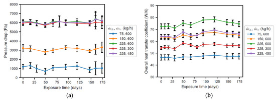
Figure 6.
Results of the experiments showing (a) the pressure drop; and (b) the heat transfer coefficient.
The results indicate that the flow cross section of the inner tube (not presented) did not vary significantly over time, as the pressure drop was essentially constant. However, a thin corrosion layer could still be possible.
Before the start of the experiment, the solution was present in static conditions, possibly allowing for the formation of the initial iron carbonate layer. The removal of this originally present corrosion layer and its insulating properties, as was expected from the results in Figure 3b and discussed in Section 3.2, would also explain the initially increasing total heat transfer coefficient and corrosion rate. In other words, during the transformation from a carbonate layer to an oxide layer, the bare material loses the protection provided by the corrosion products, and the total wall thickness decreases, resulting in an increasing corrosion rate and heat transfer coefficient, respectively. Furthermore, the continuous thinning of the tube wall by corrosion could further increase heat transfer. Once the corrosion layer started to reform (approximately after 28 days, see Figure 3b), the corrosion rate was sufficiently high to induce rapid thinning of the tube wall. This thinning then explains the further increase in the total heat transfer coefficient up to an exposure time of 120 days. In a later stage, the heat transfer coefficient decreases once the increasing heat transfer resistance of the corrosion product layer counters the wall thinning from corrosion. Note that, due to the insulating capacity of oxides, a thin layer of corrosion products would be sufficient to cause a clear decrease in the overall heat transfer rate. Therefore, the thickness of the initial and newly developed corrosion layer was insufficient to alter the flow pattern, and the pressure drop remained virtually constant.
From the above discussion, it can be concluded that the heat transfer coefficient could possibly be used as an indicator for corrosion once steady-state operating conditions are obtained. The idea is that a changing heat transfer coefficient could be an indication of a change in the tube wall roughness and/or thickness. However, a replacement of the corrosion layer, i.e., transient behavior, could also result in an increased heat transfer coefficient. Moreover, it is unclear whether a decreasing tube wall thickness could be countered by an increasing corrosion layer thickness. These two considerations prove that further optimization of the experimental procedure is required before the potential use of the heat transfer coefficient could more effectively be substantiated as an indicator of corrosion.
4. Conclusions
Experiments were performed to study the interaction between corrosion and the thermohydraulic behavior inside a heat exchanger.
| Static vs. dynamic | Carbonates form under static conditions, whereas oxides form under dynamic conditions. |
| Effect of temperature | The corrosion rate in static conditions showed a local maximum, probably because of the counteracting effects of the Arrhenius law and the carbonate solubility. In dynamic conditions, the corrosion rate increased with increasing temperature, which could be explained by the Arrhenius relation. |
| Exposure time | The uniform corrosion rate first increased, then decreased, and eventually stabilized around 0.44 mm/y (at 80 °C). This trend is possibly related to the replacement of the initially present carbonate layer with a more stable oxide layer. |
| Pressure drop | The pressure drop over the heat exchanger appeared to remain unchanged. |
| Heat transfer coefficient | The heat transfer coefficient increased during the first 120 days to 106% of the initial value (i.e., an increase of almost 6%), but then decreased again. |
| Corrosion indicator | Overall, the influence of corrosion on the thermohydraulic performance was limited. It is clear that the pressure drop over the heat exchanger cannot be used as an indicator of corrosion. On the other hand, an increasing heat transfer coefficient might be able to indicate heat exchanger tube thinning. However, further research is required to know whether the growth of a corrosion layer could counter this increasing heat transfer coefficient. |
Whether a heat exchanger with carbon steel tubes, behaving as illustrated in the setup, would be a viable alternative for titanium (or highly alloyed stainless steel types) requires further measurements. The fact that the performance did not degrade under the current conditions suggests that, in practice, the corrosion process would not jeopardize the required power output. However, a uniform corrosion rate of 0.44 mm/y does imply that carbon steel tubes (although cheaper than titanium tubes) would need to be replaced regularly.
Author Contributions
Conceptualization, W.F., T.D., S.L., M.D.P. and K.V.; methodology, W.F., S.L. and M.D.P.; validation, W.F.; formal analysis, A.S. and W.F.; investigation, W.F.; resources, T.D., S.L., M.D.P. and K.V.; data curation, T.D., S.L., M.D.P. and K.V.; writing—original draft preparation, A.S.; writing—review and editing, A.S., W.F., T.D., S.L., M.D.P. and K.V.; visualization, A.S. and W.F.; supervision, T.D., S.L., M.D.P. and K.V.; project administration, W.F.; funding acquisition, T.D., S.L., M.D.P. and K.V. All authors have read and agreed to the published version of the manuscript.
Funding
This research was funded by the Special Research Fund (BOF, UGent), grant BOF/01J06917 and BOF/GOA/026. Additionally, we gratefully acknowledge the financial support of the Flemish Government and Flanders Innovation & Entrepreneurship (VLAIO) through the Moonshot project Upheat-INES (HBC.2022.0539).
Data Availability Statement
The original contributions presented in the study are included in the article, and further inquiries can be directed to the corresponding authors.
Acknowledgments
This work was carried out with the support of the EU, ERDF, Flanders Innovation & Entrepreneurship, and the Province of Limburg.
Conflicts of Interest
The authors declare no conflict of interest. The funders had no role in the design of the study; in the collection, analyses, or interpretation of data; in the writing of the manuscript; or in the decision to publish the results.
References
- Koch, G.; Varney, J.; Thompson, N.; Moghissi, O.; Gould, M.; Payer, J. International Measures of Prevention, Application, and Economics of Corrosion Technologies Study; NACE International: Houston, TX, USA, 2016. [Google Scholar]
- SOCORRO. Challenge. Available online: https://www.socorro.eu/ (accessed on 4 February 2024).
- Roberge, P.R. Corrosion Engineering—Practices vs. Principles; McGraw Hill: New York City, NY, USA, 2008. [Google Scholar] [CrossRef]
- Electric Power Research Institute; Gorman, J.; Arey, M.; Koch, G. Cost of Corrosion in the Electric Power Industry; Electric Power Research Institute: Washington, DC, USA, 2001. [Google Scholar]
- Syrett, B.C.; Gorman, J.A. Cost of corrosion in the electric power industry: An update. Mater. Perform. 2002, 42, 32–38. [Google Scholar]
- Biezma, M.V.; Cristóbal, J.R.S. Methodology to study cost of corrosion. Corros. Eng. Sci. Technol. 2005, 40, 344–352. [Google Scholar] [CrossRef]
- Ermolina, L.V.; Alekina, E.V.; Sorokina, L.V. Methods of Corrosion Mitigation in the Gas and Oil Industry. In Proceedings of the International Conference Engineering Innovations and Sustainable Development (Springer Nature), Tanjungpinang, Indonesia, 11–13 October 2022; pp. 135–143. [Google Scholar]
- Briffa, J.; Sinagra, E.; Blundell, R. Heavy metal pollution in the environment and their toxicological effects on humans. Heliyon 2020, 6, e04691. [Google Scholar] [CrossRef] [PubMed]
- Tchounwou, P.B.; Yedjou, C.G.; Patlolla, A.K.; Sutton, D.J. Heavy Metal Toxicity and the Environment. In Molecular, Clinical and Environmental Toxicology; Springer: Berlin/Heidelberg, Germany, 2012; pp. 133–164. Available online: https://link.springer.com/chapter/10.1007/978-3-7643-8340-4_6#citeas (accessed on 4 February 2024).
- STOUT. Rare Earth Risk: How Material Scarcity May Impact Risk in Damages Projections. Available online: https://www.stout.com/en/insights/article/rare-earth-risk-how-material-scarcity-may-impact-risk-damages-projections (accessed on 4 February 2024).
- Henckens, T. Scarce mineral resources: Extraction, consumption and limits of sustainability. Resour. Conserv. Recycl. 2021, 169, 105511. [Google Scholar] [CrossRef]
- WorldStainless. Stainless Steels and CO2: Industry Emissions and Related Data. Available online: https://www.worldstainless.org/about-stainless/environment/stainless-steels-and-co2-industry-emissions-and-related-data/ (accessed on 4 February 2024).
- European Commission. EU Climate Targets: How to Decarbonise the Steel Industry. EU Science Hub. 2022. Available online: https://joint-research-centre.ec.europa.eu/jrc-news-and-updates/eu-climate-targets-how-decarbonise-steel-industry-2022-06-15_en (accessed on 4 February 2024).
- IEA. Steel. Available online: https://www.iea.org/energy-system/industry/steel (accessed on 4 February 2024).
- Worldsteel. Association. Climate Change and the Production of Iron and Steel. Available online: https://worldsteel.org/publications/policy-papers/climate-change-policy-paper/ (accessed on 4 February 2024).
- Lancaster, J.F. Corrosion and Other Types of Damage. In Heat Exchanger Design Handbook; Hemisphere Publishing Corporation: London, UK, 2023. [Google Scholar] [CrossRef]
- Faes, W.; Lecompte, S.; Ahmed, Z.Y.; Van Bael, J.; Salenbien, R.; Verbeken, K.; De Paepe, M. Corrosion and corrosion prevention in heat exchangers. Corros. Rev. 2019, 37, 131–155. [Google Scholar] [CrossRef]
- Kuźnicka, B. Erosion-corrosion of heat exchanger tubes. Eng. Fail. Anal. 2009, 16, 2382–2387. [Google Scholar] [CrossRef]
- Xie, J.; Yazdanfar, K.; Anning, G.; Rockwell, T.; Ahmed, A. Corrosion of a Vertical Shell and Tube Heat Exchanger; NACE CORROSION: Dallas, TX, USA, 2015. [Google Scholar]
- Deen, K.M.; Virk, M.A.; Haque, C.I.; Ahmad, R.; Khan, I.H. Failure investigation of heat exchanger plates due to pitting corrosion. Eng. Fail. Anal. 2010, 17, 886–893. [Google Scholar] [CrossRef]
- Turissini, R.L.; Bruno, T.V.; Dahlberg, E.P.; Setterlund, R.B. Corrosion Failures in Plate Heat Exchangers; NACE CORROSION: New Orleans, LA, USA, 1997. [Google Scholar]
- Pessu, F.O.; Saleem, E.; Espejo, C.; Neville, A. Understanding the local pitting corrosion characteristics of carbon steel in CO2 corrosion environment using artificially machined pits. Results Eng. 2022, 16, 14. [Google Scholar] [CrossRef]
- Faes, W.; Lecompte, S.; Van Bael, J.; Salenbien, R.; Bäßler, R.; Bellemans, I.; Cools, P.; De Geyter, N.; Morent, R.; Verbeken, K.; et al. Corrosion behaviour of different steel types in artificial geothermal fluids. Geothermics 2019, 82, 182–189. [Google Scholar] [CrossRef]
- Bureau for Standardisation. NBN EN 10305-4: Steel Tubes for Precision Applications—Technical Delivery Conditions—Part 4: Seamless Cold Drawn Tubes for Hydraulic and Pneumatic Power Systems. Available online: https://www.nen.nl/nen-en-10305-4-2016-en-218388 (accessed on 27 January 2023).
- Zhao, Y.; Qi, Z.; Wang, Q.; Chen, J.; Shen, J. Effect of corrosion on performance of fin-and-tube heat exchangers with different fin materials. Exp. Therm. Fluid Sci. 2012, 37, 98–103. [Google Scholar] [CrossRef]
- Laird Thermal Systems. Corrosion Prevention in Cooling Loops. Available online: https://lairdthermal.com/thermal-technical-library/application-notes/corrosion-prevention-cooling-loops (accessed on 4 February 2024).
- De Ketelaere, E.; Moed, D.; Vanoppen, M.; Verliefde, A.R.D.; Verbeken, K.; Depover, T. Sodium silicate corrosion inhibition behaviour for carbon steel in a dynamic salt water environment. Corros. Sci. 2023, 217, 111119. [Google Scholar] [CrossRef]
- Tummers, M.J.; Steunebrink, M. Effect of surface roughness on heat transfer in Rayleigh-Bénard convection. Int. J. Heat Mass Transf. 2019, 139, 1056–1064. [Google Scholar] [CrossRef]
- Geete, A.; Pathak, R. Effect of surface roughness on the performance of heat exchanger. SN Appl. Sci. 2019, 1, 901. [Google Scholar] [CrossRef]
- Burkle, D.P. Understanding the Formation of Protective FeCO3 on to Carbon Steel Pipelines during CO2 Corrosion. Ph.D. Thesis, University of Leeds, Leeds, UK, 2017. Available online: http://etheses.whiterose.ac.uk/17608/ (accessed on 4 February 2024).
- Silva, P.N.; Svenningsen, G.; Dugstad, A.; Gomes, J.A.C.P. The effect of oxygen on the CO2 corrosion of tensile wires in simulated annulus environments of flexible pipes. Mater. Corros. 2022, 73, 669–686. [Google Scholar] [CrossRef]
Disclaimer/Publisher’s Note: The statements, opinions and data contained in all publications are solely those of the individual author(s) and contributor(s) and not of MDPI and/or the editor(s). MDPI and/or the editor(s) disclaim responsibility for any injury to people or property resulting from any ideas, methods, instructions or products referred to in the content. |
© 2024 by the authors. Licensee MDPI, Basel, Switzerland. This article is an open access article distributed under the terms and conditions of the Creative Commons Attribution (CC BY) license (https://creativecommons.org/licenses/by/4.0/).

