
Effect of Different Microstructures on Surface Residual Stress of Induction-Hardened Bearing Steel

Abstract
1. Introduction
2. Materials and Methods
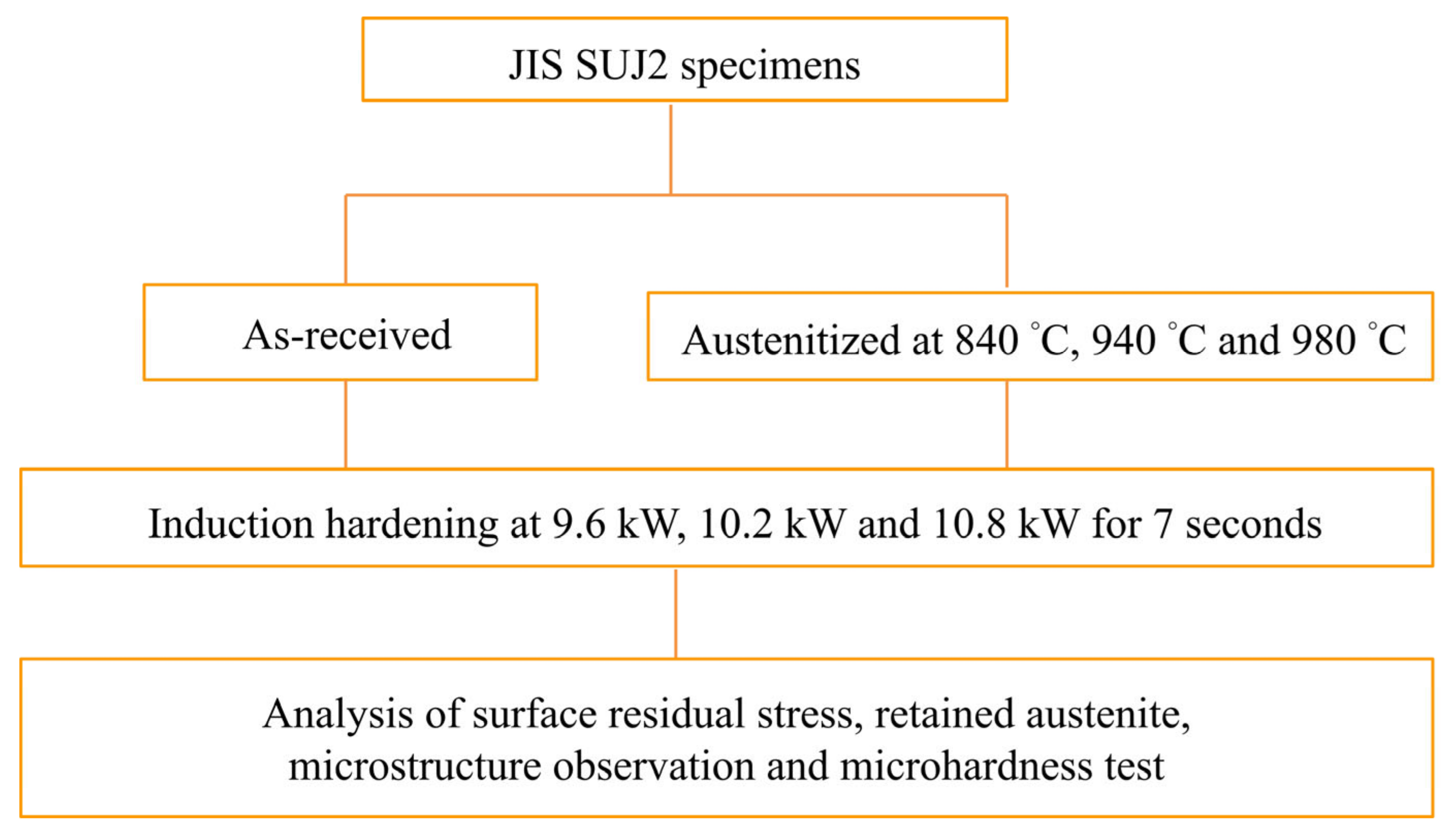
2.1. Specimens Preparation
2.2. Heat Treatment Process
2.3. Experimental Methods
2.3.1. Microstructure Observation
2.3.2. Hardness Test
2.3.3. X-ray Diffraction
3. Results and Discussion
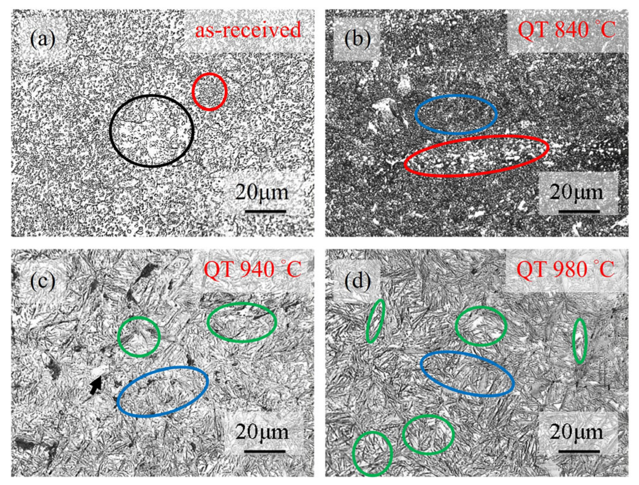
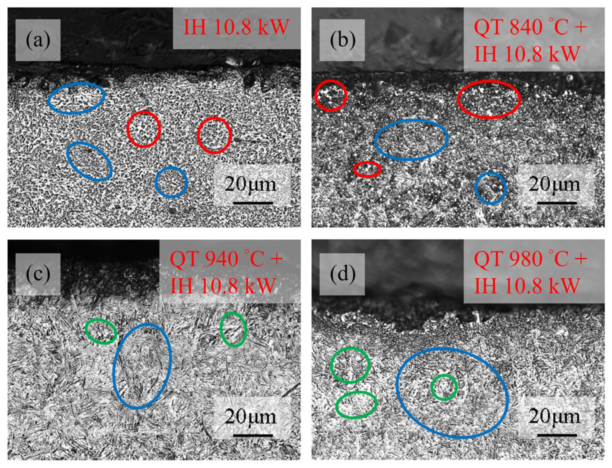
3.1. Microstructure
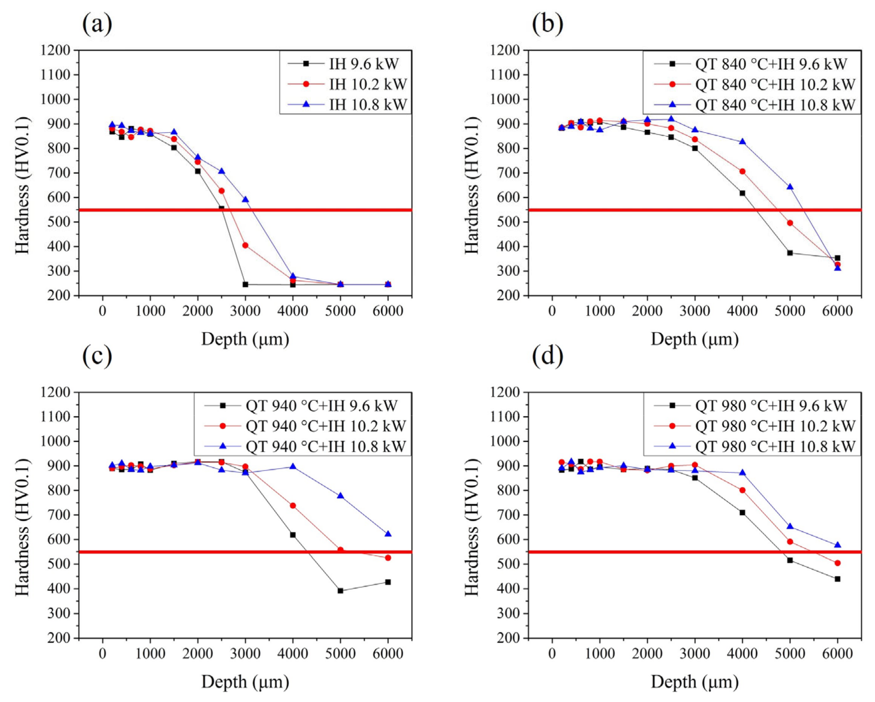
3.2. Hardness
3.3. X-ray Diffraction
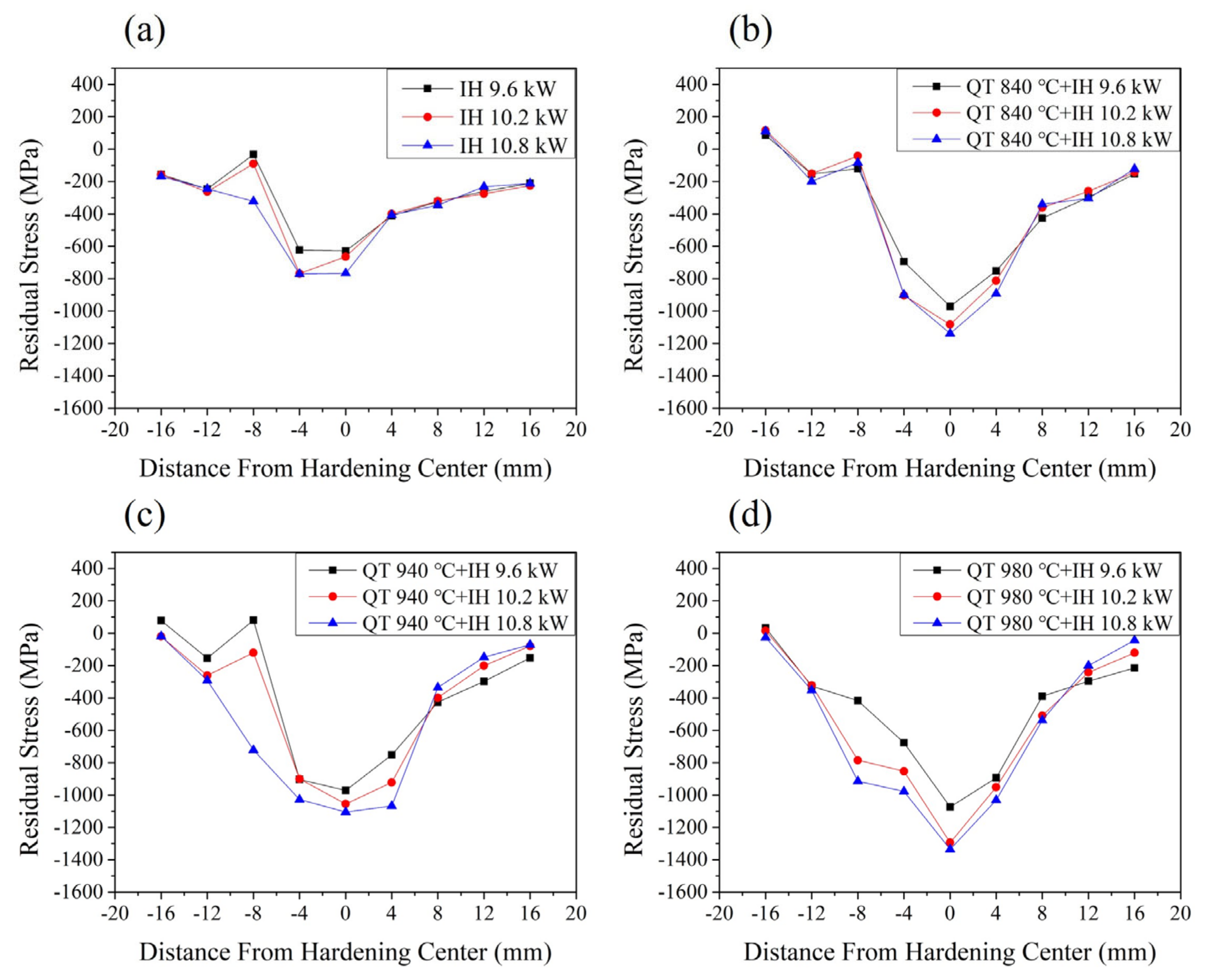
3.3.1. Residual Stress
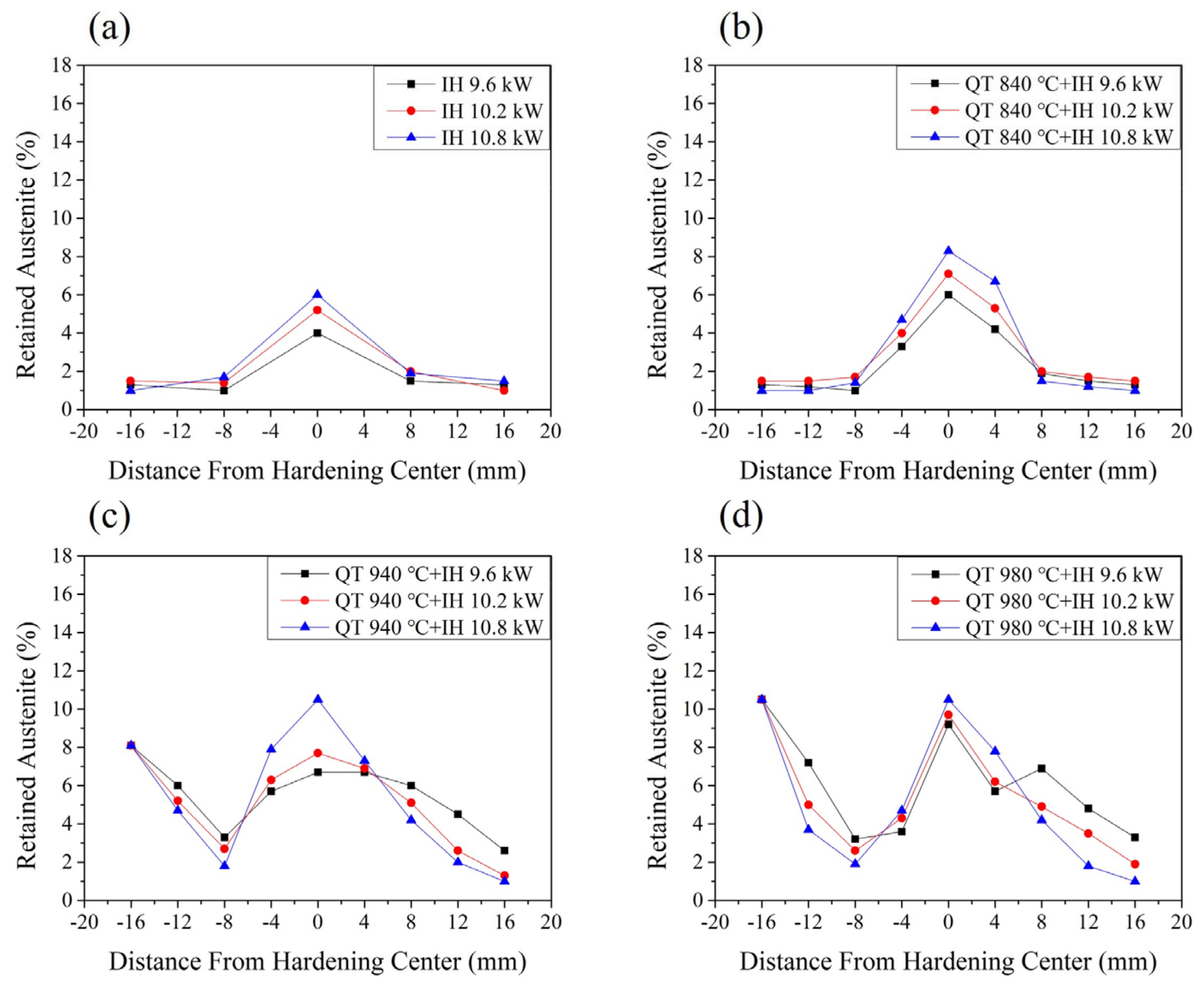
3.3.2. Retained Austenite
4. Conclusions
- The microstructure of the material before induction hardening has a significant impact on the effective case depth under the same output power conditions. The effective case depth of the tempered martensite structure after induction hardening is deeper than that of the spheroidized structure. The spheroidized structure was treated by the induction hardening method at 9.6 kW, and its effective case depth was only 2.5 mm. If the microstructure is tempered martensite before induction-re-hardening treatment, the effective case depth of the induction-hardened specimens with an induction power of 9.6 kW can be increased to 4.2 mm.
- Because the hardened center by induction method will be subject to more severe temperature changes, the phase transformation caused by the supercooling driving force and the thermal stress caused by the temperature gradient is more effective. The hardened center area during induction hardening has the highest residual compressive stress value. The specimen was hardened by the induction-hardening method at 10.8 kW and the surface residual compressive stress value of the hardening center was able to reach −766 MPa. As the distance from the hardening center increases, the residual compressive stress value will gradually decrease.
- During the induction hardening process, the phase transformation of the martensite structure caused more internal stress due to hardening treatment. The maximum surface residual compressive stress value of the specimen that was austenitized at 980 °C and induction hardened with an induction power of 9.6 kW specimen is −1073 MPa.
- The SUJ2 specimen that will have a wider stress influence range under the condition of the microstructure before induction hardening is that of tempered martensite. The effective stress influence range of the induction-hardened specimen austenitized at 980 °C and induction hardened with an induction power of 9.6 kW can reach 16 mm.
- The heat-affected zone is lower than the hardened center region during induction hardening. The content of retained austenite measured in the heat-affected zone will be less. The retained austenite in the heat-affected zone can be decreased from 9% to a minimum of 2%.
Author Contributions
Funding
Data Availability Statement
Acknowledgments
Conflicts of Interest
References
- Fernandes, A.P.; Gallego, J.; Picon, C.A.; Filho, G.T.; Casteletti, L.C. Wear and corrosion of niobium carbide coated AISI 52100 bearing steel. Surf. Coat. Technol. 2015, 279, 112–117. [Google Scholar] [CrossRef]
- Hisakado, T.; Miura, K.; Suda, H. Effects of debris transfer and abrasive particle damage on the abrasive wear of hardened bearing steel. Wear 2001, 247, 24–32. [Google Scholar] [CrossRef]
- Matsunaga, H.; Komata, H.; Yamabe, J.; Fukushima, Y.; Matsuoka, S. Effect of Size and Depth of Small Defect on the Rolling Contact Fatigue Strength of Bearing Steel JIS-SUJ2. Procedia Mater. Sci. 2014, 3, 1663–1668. [Google Scholar] [CrossRef]
- Hwang, H.; De Cooman, B.C. Influence of the initial microstructure on the spheroidization of SAE 52100 bearing steel. Steel Res. Int. 2016, 87, 112–125. [Google Scholar] [CrossRef]
- Sun, J.; Wood, R.J.K.; Wang, L.; Care, I.; Powrie, H.E.G. Wear monitoring of bearing steel using electrostatic and acoustic emission techniques. Wear 2005, 259, 1482–1489. [Google Scholar] [CrossRef]
- Rivero, I.V.; Ruud, C.O. Deviation of residual stress patterns in 52100 bearing steel due to inherent microstructural transformations after rolling contact. Mater. Charact. 2004, 53, 381–393. [Google Scholar] [CrossRef]
- Roy, S.; Sundararajan, S. Effect of retained austenite on spalling behavior of carburized AISI 8620 steel under boundary lubrication. J. Mater. Res. Technol. 2019, 119, 238–246. [Google Scholar] [CrossRef]
- Šmeļova, V.; Schwedt, A.; Wang, L.; Holweger, W.; Mayer, J. Electron microscopy investigations of microstructural alterations due to classical rolling contact fatigue (RCF) in martensitic AISI 52100 bearing steel. Int. J. Fatigue 2017, 98, 142–154. [Google Scholar] [CrossRef]
- Ostermayer, P.; Burkart, K.; Blinn, B.; Surm, H.; Clausen, B.; Beck, T. Evaluation of the plastic deformation behavior of modified 100Cr6 steels with increased fractions of retained austenite using cyclic indentation tests. Mater. Test. 2022, 64, 1298–1312. [Google Scholar] [CrossRef]
- Huang, M.S.; Huang, Y.L. Effect of multi-layered induction coils on efficiency and uniformity of surface heating. Int. J. Heat Mass Transf. 2010, 53, 2414–2423. [Google Scholar] [CrossRef]
- Cao, Y.J.; Sun, J.Q.; Ma, F.; Chen, Y.Y.; Cheng, X.Z.; Gao, X.; Xie, K. Effect of the microstructure and residual stress on tribological behavior of induction hardened GCr15 steel. Tribol. Int. 2017, 115, 108–115. [Google Scholar] [CrossRef]
- Torkamani, H.; Vrček, A.; Larsson, R.; Antti, M.L. Micro-pitting and wear damage characterization of through hardened 100Cr6 and surface induction hardened C56E2 bearing steels. Wear 2022, 492–493, 204218. [Google Scholar] [CrossRef]
- Schüßler, P.; Damon, J.; Mühl, F.; Dietrich, S.; Schulze, V. Laser surface hardening: A simulative study of tempering mechanisms on hardness and residual stress. Comput. Mater. Sci. 2023, 221, 112079. [Google Scholar] [CrossRef]
- Li, H.P.; Sun, Y.; He, L.F.; Li, Z.C. Failure analysis of ball screw in the progressive induction hardening and finishing machining. Eng. Fail. Anal. 2023, 151, 107410. [Google Scholar] [CrossRef]
- Mühl, F.; Damon, J.; Dietrich, S.; Schulze, V. Simulation of induction hardening: Simulative sensitivity analysis with respect to material parameters and the surface layer state. Comput. Mater. Sci. 2020, 184, 109916. [Google Scholar] [CrossRef]
- Areitioaurtena, M.; Segurajauregi, U.; Fisk, M.; Cabello, M.J.; Ukar, E. Influence of induction hardening residual stresses on rolling contact fatigue lifetime. Int. J. Fatigue 2022, 23, 106781. [Google Scholar] [CrossRef]
- Hu, Y.; Qin, Q.; Wu, S.; Zhao, X.; Wang, W. Fatigue resistance and remaining life assessment of induction-hardened S38C steel railway axles. Int. J. Fatigue 2021, 144, 106068. [Google Scholar] [CrossRef]
- Gao, J.W.; Pan, X.N.; Han, J.; Zhu, S.P.; Liao, D.; Li, Y.B.; Dai, G.Z. Influence of artificial defects on fatigue strength of induction hardened S38C axles. Int. J. Fatigue 2020, 139, 105746. [Google Scholar] [CrossRef]
- Hayama, M.; Kikuchi, S.; Tsukahara, M.; Misaka, Y.; Komotori, J. Estimation of residual stress relaxation in low alloy steel with different hardness during fatigue by in situ X-ray measurement. Int. J. Fatigue 2024, 178, 107989. [Google Scholar] [CrossRef]
- Li, B.Z.; Jiang, X.H.; Yang, J.G.; Liang, S.Y. Effects of depth of cut on the redistribution of residual stress and distortion during the milling of thin-walled part. J. Mater. Process. Technol. 2015, 216, 223–233. [Google Scholar] [CrossRef]
- Rech, J.; Kermouche, G.; Grzesik, W.; Garcia-Rosales, C.; Khellouki, A.; Garcia-Navas, V. Characterization and modelling of the residual stresses induced by belt finishing on a AISI52100 hardened steel. J. Mater. Process. Technol. 2008, 208, 187–195. [Google Scholar] [CrossRef]
- Silveira, E.; Irisarri, A.M. Study on the distortion of steel worm shafts. Eng. Fail. Anal. 2009, 16, 1090–1096. [Google Scholar] [CrossRef]
- Xiao, G.; Chen, B.; Li, S.; Zhuo, X. Fatigue life analysis of aero-engine blades for abrasive belt grinding considering residual stress. Eng. Fail. Anal. 2022, 131, 105846. [Google Scholar] [CrossRef]
- Ao, S.S.; Li, C.J.; Huang, Y.F.; Luo, Z. Determination of residual stress in resistance spot-welded joint by a novel X-ray diffraction. Measurement 2020, 161, 107892. [Google Scholar] [CrossRef]
- Tanaka, K. The cosα method for X-ray residual stress measurement using two-dimensional detector. Mech. Eng. Rev. 2019, 6, 378. [Google Scholar] [CrossRef]
- ASTM E975-13; Standard Practice for X-ray Determination of Retained Austenite in Steel with Near Random Crystallographic Orientation. ASTM International: West Conshohocken, PA, USA, 2013.
- Zhang, C.L.; Liu, X.; Zhang, D.; Xie, L.Y.; Zhou, L.Y.; Liu, Y.Z. Carbide inheritance of pearlite spheroidization during heat treatment process in GCr15 steel. Trans. Mater. Heat Treat. 2014, 35, 45–48. [Google Scholar]
- Wang, Z.N.; Cui, H.Z.; Zhang, G.S.; Wang, W.; Sun, J.Q.; Cheng, G.Q. Microstructure and room-temperature dry sliding wear behavior of GCr15 steel treated by surface induction hardening. Trans. Mater. Heat Treat. 2015, 36, 180–187. [Google Scholar]
- Bhadeshia, H.K.D.H. Steels for bearings. Prog. Mater. Sci. 2012, 57, 268–435. [Google Scholar] [CrossRef]
- Li, G.; Xiang, J.; Kuang, J.; Jia, M.D. Microstructure and properties of GCr15 steel treated by laser quenching. Trans. Mater. Heat Treat. 2010, 31, 129–132. [Google Scholar]
- Gai, Y.H.; Yan, Y.; Li, C.N.; Li, B.M.; Du, W.; Li, M.S. Fatigue test and failure analysis of Cr Mo steel ball screw pair. Trans. Mater. Heat Treat. 2015, 36, 148–155. [Google Scholar]
- Holmberg, J.; Steuwer, A.; Stormvinter, A.; Kristoffersen, H.; Haakanen, M.; Berglund, J. Residual stress state in an induction hardened steel bar determined by synchrotron- and neutron diffraction compared to results from lab-XRD. Mater. Sci. Eng. A 2016, 667, 199–207. [Google Scholar] [CrossRef]
- Yi, J.; Gharghouri, M.; Bocher, P.; Medraj, M. Distortion and residual stress measurements of induction hardened AISI 4340 discs. Mater. Chem. Phys. 2013, 142, 248–258. [Google Scholar] [CrossRef]
- Cui, W.; San-Martín, D.; Rivera-Díaz-del-Castillo, P.E.J. Stability of retained austenite in martensitic high carbon steels. Part I: Thermal stability. Mater. Sci. Eng. 2018, 711, 683–695. [Google Scholar] [CrossRef]


| C | Si | Mn | P | Cr | Ni | Cu | Fe |
|---|---|---|---|---|---|---|---|
| 1.05 | 0.243 | 0.426 | 0.0201 | 0.0147 | 0.0948 | 0.101 | Bal. |
| As-Received | 840 °C QT * | 940 °C QT * | 980 °C QT * | |
|---|---|---|---|---|
| HRC | 19 ± 1 | 60 ± 1 | 60 ± 1 | 60 ± 1 |
| RS (MPa) | −77 | 106 | 118 | 130 |
| γ (%) | 0.2 | 0.7 | 5.1 | 9.0 |
Disclaimer/Publisher’s Note: The statements, opinions and data contained in all publications are solely those of the individual author(s) and contributor(s) and not of MDPI and/or the editor(s). MDPI and/or the editor(s) disclaim responsibility for any injury to people or property resulting from any ideas, methods, instructions or products referred to in the content. |
© 2024 by the authors. Licensee MDPI, Basel, Switzerland. This article is an open access article distributed under the terms and conditions of the Creative Commons Attribution (CC BY) license (https://creativecommons.org/licenses/by/4.0/).
Share and Cite
Lu, S.-Q.; Chiu, L.-H. Effect of Different Microstructures on Surface Residual Stress of Induction-Hardened Bearing Steel. Metals 2024, 14, 201. https://doi.org/10.3390/met14020201
Lu S-Q, Chiu L-H. Effect of Different Microstructures on Surface Residual Stress of Induction-Hardened Bearing Steel. Metals. 2024; 14(2):201. https://doi.org/10.3390/met14020201
Chicago/Turabian StyleLu, Shao-Quan, and Liu-Ho Chiu. 2024. "Effect of Different Microstructures on Surface Residual Stress of Induction-Hardened Bearing Steel" Metals 14, no. 2: 201. https://doi.org/10.3390/met14020201
APA StyleLu, S.-Q., & Chiu, L.-H. (2024). Effect of Different Microstructures on Surface Residual Stress of Induction-Hardened Bearing Steel. Metals, 14(2), 201. https://doi.org/10.3390/met14020201