Article

Effect of Kaolin/TiO2 Additions and Contact Temperature on the Interaction between DD6 Alloys and Al2O3 Shells

1
State Key Laboratory of Advanced Special Steel & Shanghai Key Laboratory of Advanced Ferrometallurgy, School of Materials Science and Engineering, Shanghai University, Shanghai 200444, China
2
Zhejiang Institute of Advanced Materials, Shanghai University, Jiaxing 314100, China
3
Beijing Advanced Innovation Center for Materials Genome Engineering, Collaborative Innovation Center of Steel Technology, University of Science and Technology Beijing, Beijing 100083, China
4
Shanghai Key Laboratory for High Temperature Materials and Precision Forming, School of Materials Science and Engineering, Shanghai Jiao Tong University, Shanghai 200240, China
*
Authors to whom correspondence should be addressed.
Metals 2024, 14(2), 164; https://doi.org/10.3390/met14020164
Submission received: 22 December 2023 / Revised: 26 January 2024 / Accepted: 26 January 2024 / Published: 29 January 2024
(This article belongs to the Section Crystallography and Applications of Metallic Materials)

Abstract

:
In this study, the effects of kaolin and TiO2 additions on the interaction between DD6 alloys and Al2O3 shells were investigated at 1550 and 1600 °C, respectively. Through the use of optical microscopy and scanning electron microscopy, the phase composition and microstructure of the shells and the alloys were studied, and the interaction mechanism was clarified. The results indicate that the shells adding kaolin and TiO2 had a relatively weak interaction with the alloys at 1550 °C, and no significant sand adhesion could be observed. As the contact temperature was increased to 1600 °C, the alloy melt could permeate into the shells, resulting in the generation of a thick sand adhesion layer. The thicknesses of the attached layers in the alloys, which contacted the shell with kaolin and TiO2, were 120 and 220 μm, respectively. No significant chemical products could be detected in the interaction layer, meaning that only physical dissolution of the shell refractory occurred. This study provides an experimental foundation for improving shell performance and offers valuable references for further research in related fields.

1. Introduction

Hollow turbine blades using single-crystal nickel-based superalloys can remove transverse grain boundaries, showing exceptional high-temperature performance and thermal endurance [1,2,3]. Therefore, they find extensive use in the hot sections of cutting-edge aero-engines and industrial gas turbines. At present, the investment casting technique is a crucial approach for the preparation of the hollow turbine blades, which are structurally complex, thin-walled, and lightweight [4]. In the manufacturing process of turbine blades, the ceramic shell is contacted with the alloy melt for several hours at temperatures exceeding 1500 °C. Consequently, the interaction between the shell and the alloy directly affects the quality of the prepared alloy [5,6,7,8].
DD6 alloy is China’s domestically developed second-generation nickel-based superalloy. It has advantages such as high temperature strength, excellent comprehensive performance, stable structure, and good casting process properties [9]. Currently, Al2O3 is the most common refractory for the preparation of the shell [10]. During the casting of the DD6 alloy, the interaction between the Al2O3 shell and the alloy is one of the significant causes of the sand adhesion and internal defects. The chemical sand adhesion onto the surface of the cast component can reduce dimension accuracy and increase processing cost of the component. How to control the interaction between them has become a focal point for researchers in precision casting technology for DD6 alloys [11,12,13,14,15,16].
Researchers have suggested that the modification of the Al2O3 shell with a specific mineralizer could effectively control the interaction between the alloy and the shell [17,18]. Generally, the Al2O3 shell used for directional solidification was not sintering at a high temperature, with the result that the level of surface densification of the shell was not high [19]. Currently, in the preparation of the shell, adding an appropriate mineralizer is a common method used to lower the sintering temperature of electrofused Al2O3 resulting from forming a three-dimensional network microstructure connected by mullite bridges [20]. Thus, it could effectively improve the high-temperature performance of the Al2O3 shell. Currently, mineralizer additives for Al2O3 shells are always used in investment casting, including refractories like kaolin and TiO2 [21,22,23]. However, the studies focused on the interaction between the shells with these two types of mineralizers and DD6 alloys have not been established yet.
In this study, Al2O3 shells with additions such as kaolin and TiO2 were prepared. The interactions between the shells and DD6 alloys were investigated at temperatures of 1550 °C and 1600 °C, respectively, for 40 min. By optical microscopy (OM) and scanning electron microscopy (SEM), the interactions between them were investigated as well as the corresponding interaction mechanisms. This study provides theoretical guidance for selecting suitable additives for the preparation of high-quality Al2O3 shells as well as the fabrication of high-quality DD6 alloy.

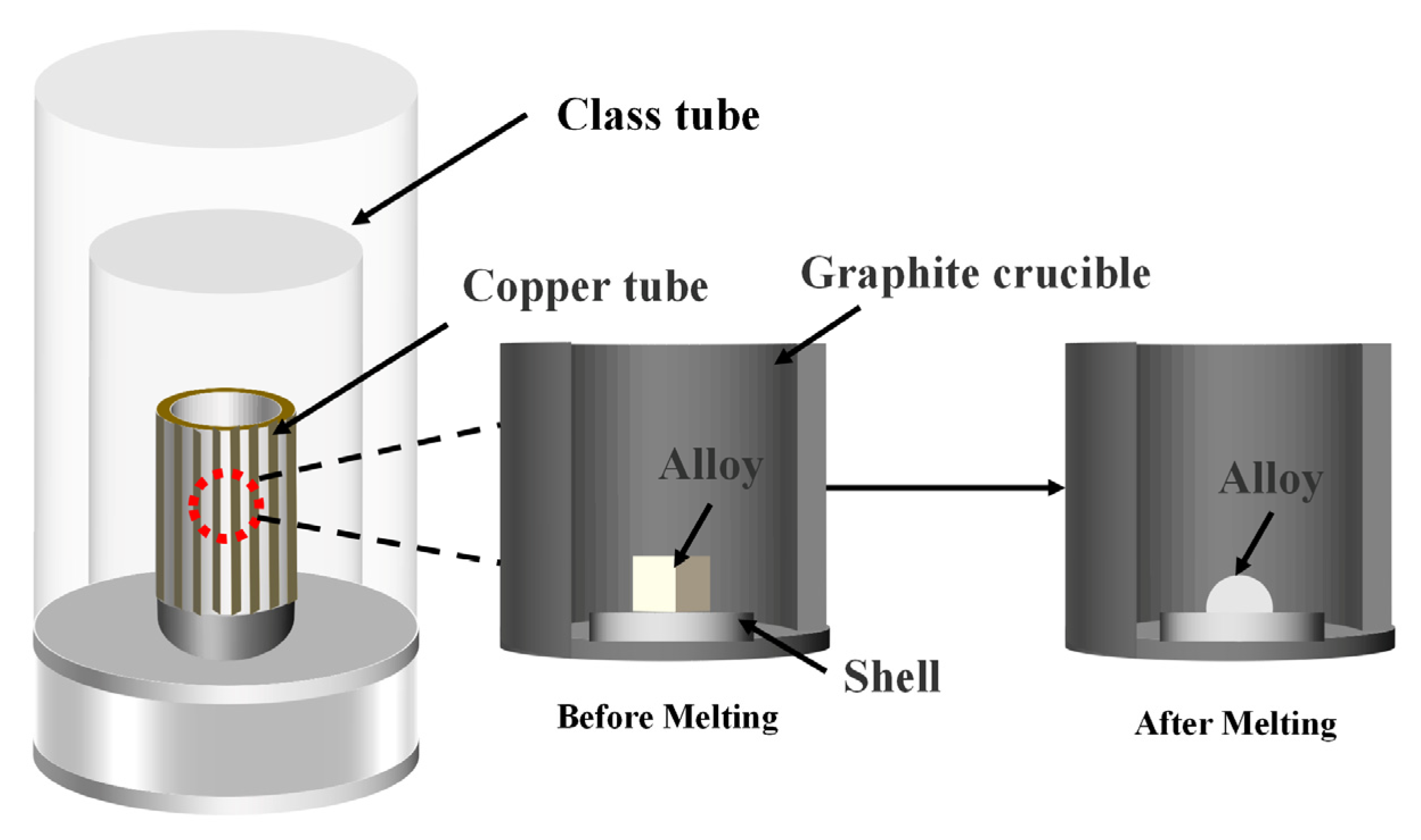
2. Experimental Procedure

The Al2O3 shell used in this study followed a conventional preparation process for investment casting. The surface layer of the shell consisted of 325-mesh Al2O3 powder, with the addition of either 1.5% by mass of kaolin or TiO2 to form composite powders, respectively. The back layer used ZrSiO4 sands, which comprised 90-mesh and 54-mesh powders. The silica sol was used as the employed binder. The powder-to-liquid ratio for the surface layer was set at 3.5:1, with the addition of dispersants, defoamers, and wetting agents for thorough mixing. After applying the slurry to the wax, the surface layer of Al2O3 powders was sprinkled. Subsequently, a ZrSiO4 back layer was prepared using the same method. Once the prepared Al2O3 shell underwent dewaxing, it was sintered at 1050 °C for 2 h in a muffle furnace.
During the contact experiment, DD6 alloy was used, and its nominal composition (wt.%) was Cr: 4.8, Co: 8.5, Mo: 1.5, W: 8.0, Ta: 7.5, Re: 2.4, Al: 6.2, Nb: 1.2, C: 0.04, and Ni in balance. The alloys were cut into a cube with a side of 5 mm for the contact experiment using the wire cutting machine. Before the experiments, the oxide layer on the surface of the alloy was thoroughly cleaned.
The contact experiments were carried out using the non-in-situ seating-drop method, which was performed in the furnace, as shown in Figure 1. Firstly, the alloy was placed on the Al2O3 shell and then inserted into a graphite crucible. Secondly, the furnace was evacuated to 3 × 10⁻² Pa and scrubbed with high-purity argon gas (purity 99.9%) three times. The experiment was carried out under a high vacuum at 1550 and 1600 °C for 40 min, respectively. The molten alloy formed hemispherical droplets after solidification. Finally, the alloy samples were taken out together with Al2O3 shells.
Before and after the contact experiment, the macro- and micromorphology of the bottom of the alloy were analyzed using optical microscopy (OM) and scanning electron microscopy (SEM, Gemini 300, Oberkochen, Germany) in combination with energy-dispersive spectroscopy (EDS). Before the analysis, the alloys were cut and inlaid. After grinding and polishing, the cross-section samples were prepared. The distribution of the alloy elements and the microstructure of the interaction layer were analyzed.

3. Results and Discussion

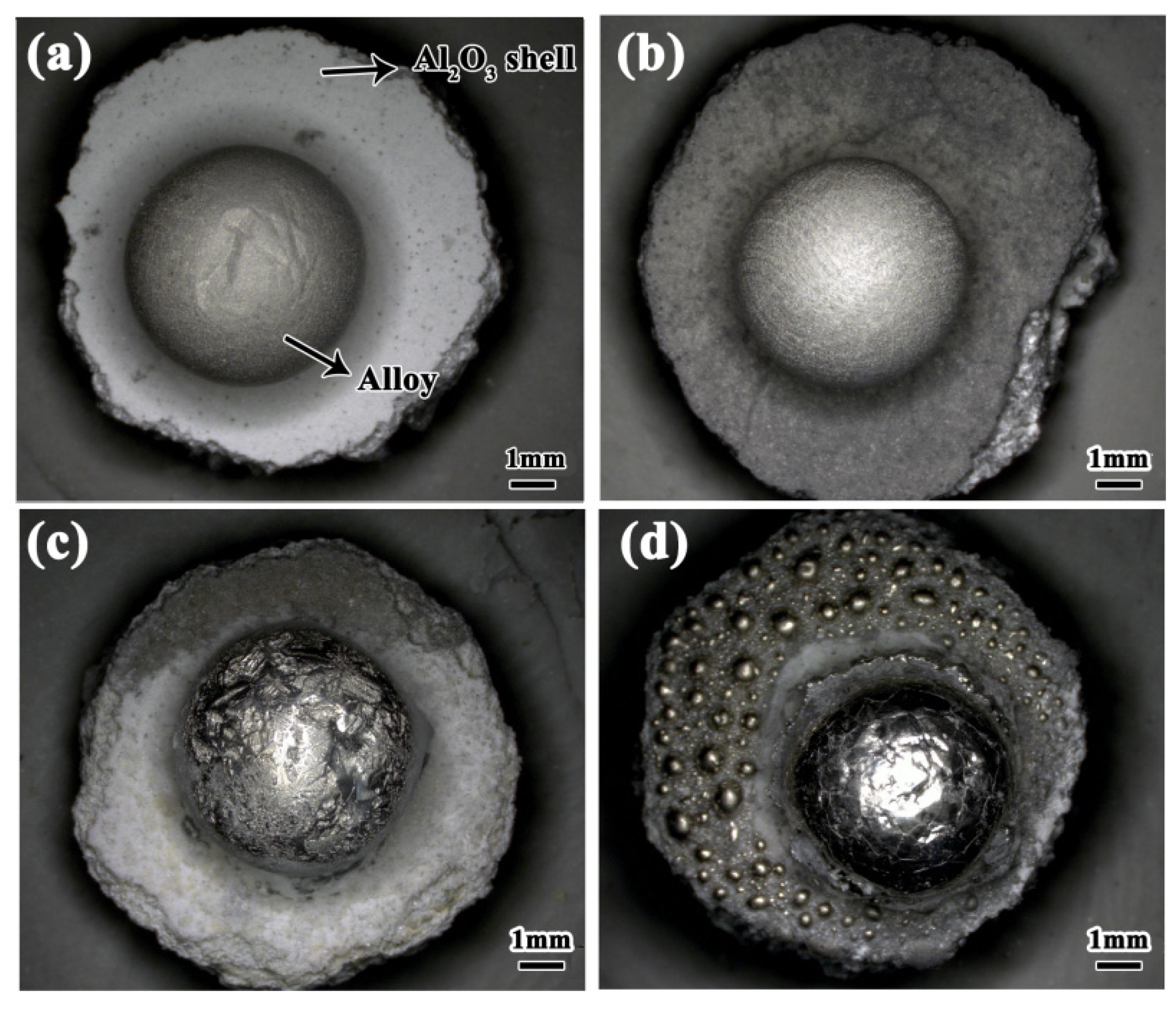
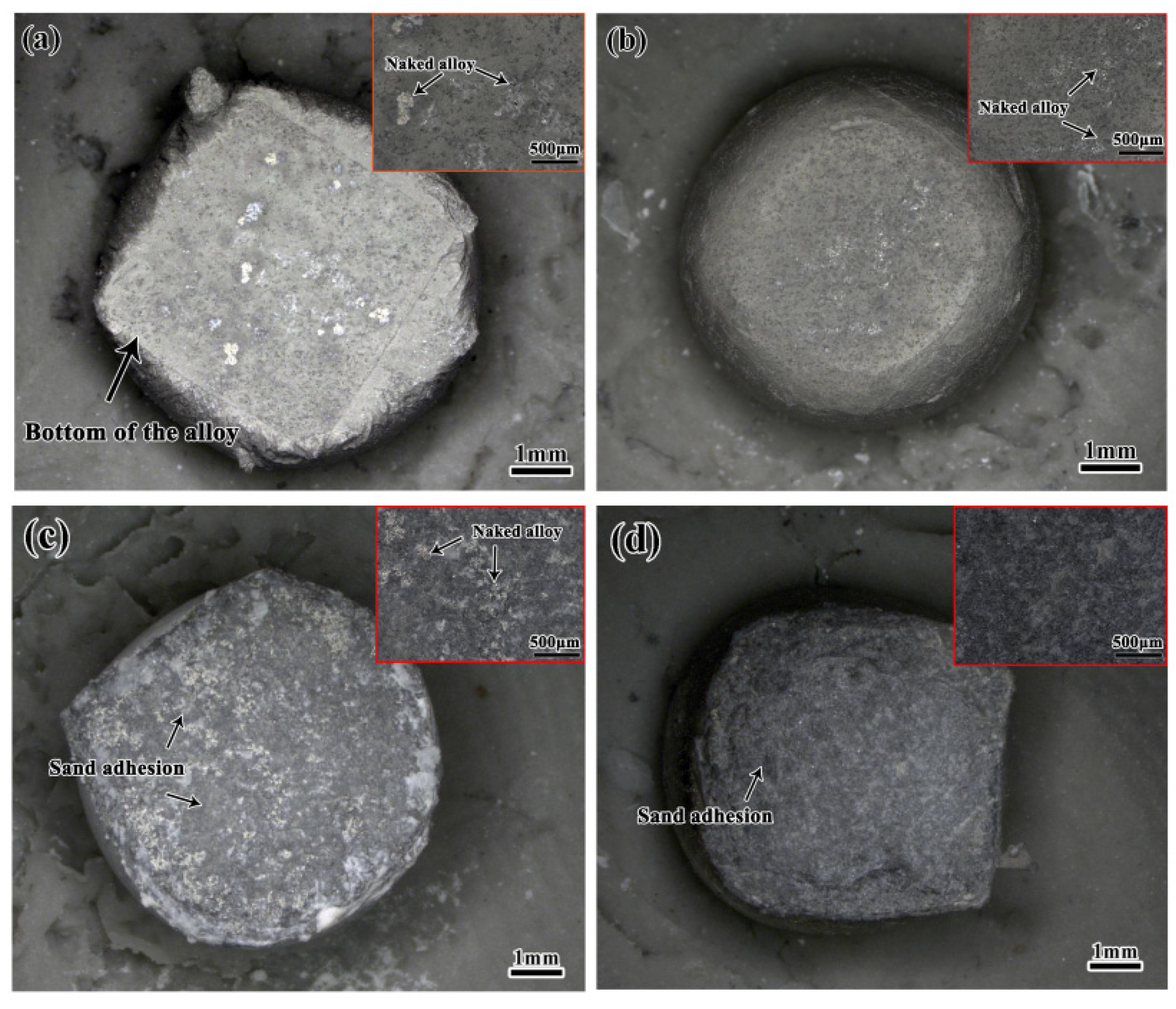
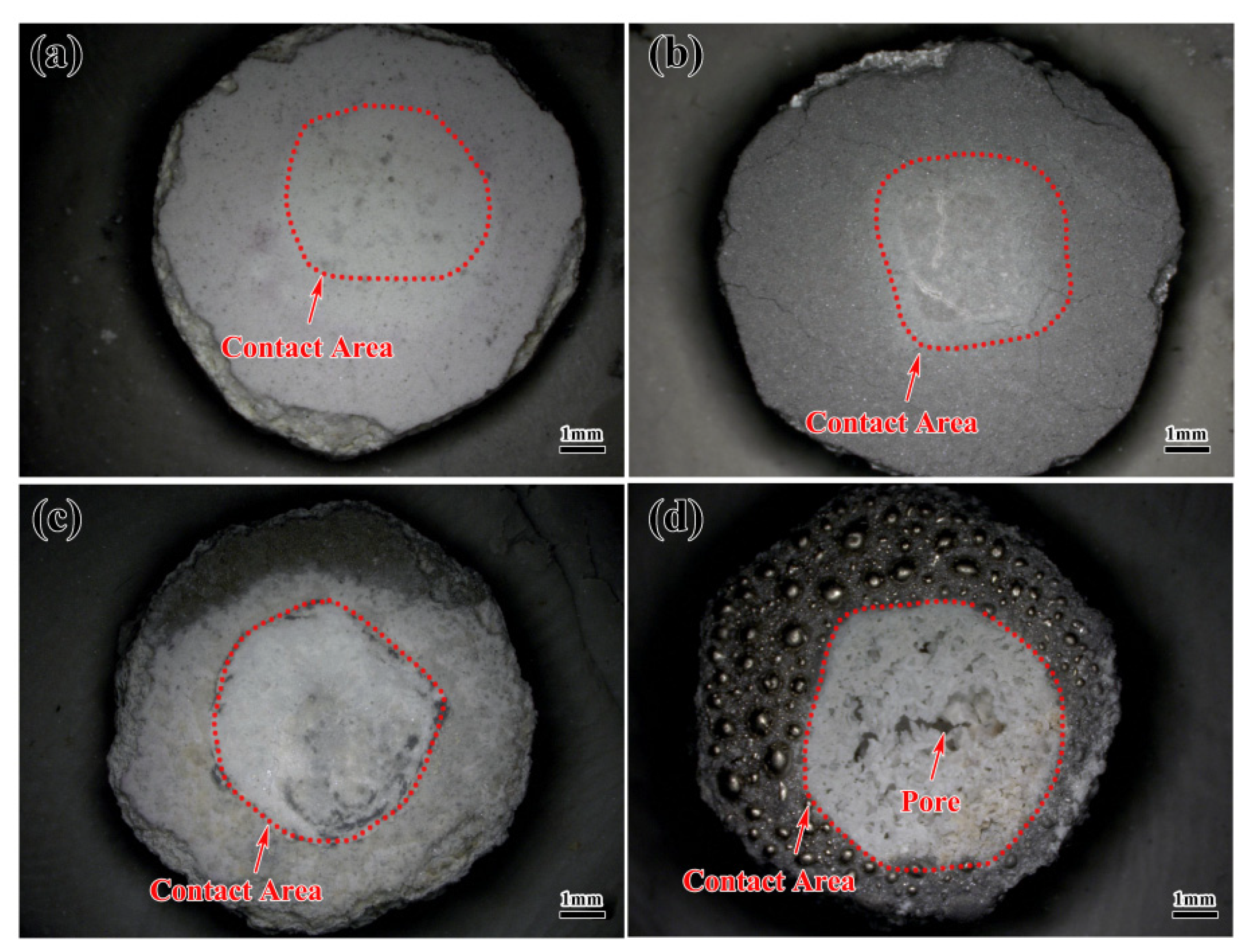
3.1. Macroscopic Morphology of the Alloys Contacted with Al2O3 Shells

Figure 2 shows the macroscopic pictures of the alloys located on Al2O3 shells. From Figure 2a, it can be seen that the alloy appeared as a nearly spherical shape with noticeable luster after contact with the shell-added kaolin at 1550 °C. The alloy located on the shell with TiO2 addition also exhibited the same morphology. However, the surface of the shell became black, as shown in Figure 2b. Apparently, after the contact temperature was increased to 1600 °C, the interaction between the alloy and the shell significantly intensified. Firstly, the morphology of the alloy was difficult to maintain as a sphere. Secondly, the surface morphology of the shell also exhibited a significant change; the surface damage was evident in contact with the alloy, as shown in Figure 2c,d.
Figure 3 shows the macroscopic morphology of the bottom of the alloys after the contact experiment. From Figure 3a, it can be seen that a distinct layer of gray substance was attached to the bottom of the alloy (referred to as sand adhesion) after contact with the shell-added kaolin at 1550 °C. Additionally, some bright white metallic areas (naked alloy) were also observed. From Figure 3b, the same phenomenon could also be observed between the alloy and the shell with TiO2 addition at 1550 °C. However, the naked alloy areas were notably smaller than those in Figure 3a, indicating that the extent of the sand adhesion was larger. After the contact temperature was increased to 1600 °C, the phenomenon of sand adhesion in the alloy became significantly more severe. From Figure 3c, it can be seen that the alloy that contacted the shell-added kaolin at 1600 °C had a large area of block-like black sand adhesion. However, there were still some naked alloys. After contact with the shell with TiO2 at 1600 °C, the sand adhesion phenomenon was the most severe. Moreover, no naked alloy could be observed any more, as shown in Figure 3d. Obviously, the corrosion resistance of the Al2O3 shell with the kaolin addition was superior to that of the Al2O3 shell with the TiO2 addition.
Figure 4 shows the macroscopic pictures of the surface of the Al2O3 shells contacted with the alloys. From Figure 4a, it can be seen that the shell with kaolin addition contacted at 1550 °C remained an intact structure without any significant changes. The contact surface between the shell and the alloy appeared white in color, while the non-contact surface showed a faint pinkish color. Additionally, the contact surface between the shell with TiO2 and the alloy appeared light gray. The non-contact surface appeared gray, as shown in Figure 4b. Despite the fact that the color of the shell changed after the experiment, there were no apparent anomalies in the surface structure of the shell. By investigating the surface morphology of the shell and the sand adhesion in Figure 2a,b, it can be concluded that the contact experiment at 1550 °C for 40 min did not cause a significant interaction. This condition was suitable for the subsequent directional solidification preparation of the DD6 alloy. Apparently, when the contact temperature was increased to 1600 °C, the interaction between the alloy and the shell significantly intensified. From Figure 4c, it can be seen that the surface of the shell with kaolin addition contacted with the alloy exhibited an incomplete structure. Compared to the morphology of the shell without contact with the alloy, the shell in contact with the alloy clearly exhibited a layered structure. It indicated that a significant interaction occurred between them. A more significant sand adhesion phenomenon could be observed in the shell with TiO2 addition at 1600 °C, as shown in Figure 4d. There were evident traces of significant peeling in the contact layer. Additionally, some pores were apparent in the shell. It could be concluded that the surface structure of the shell had been essentially disrupted. The increase in the contact temperature could intensify the interaction between them, leading to an increased level of sand adhesion. Therefore, the macroscopic internal structure of the exposed shell could be used to assess the interaction. Apparently, the shell with the kaolin addition demonstrated better corrosion resistance compared to adding TiO2.

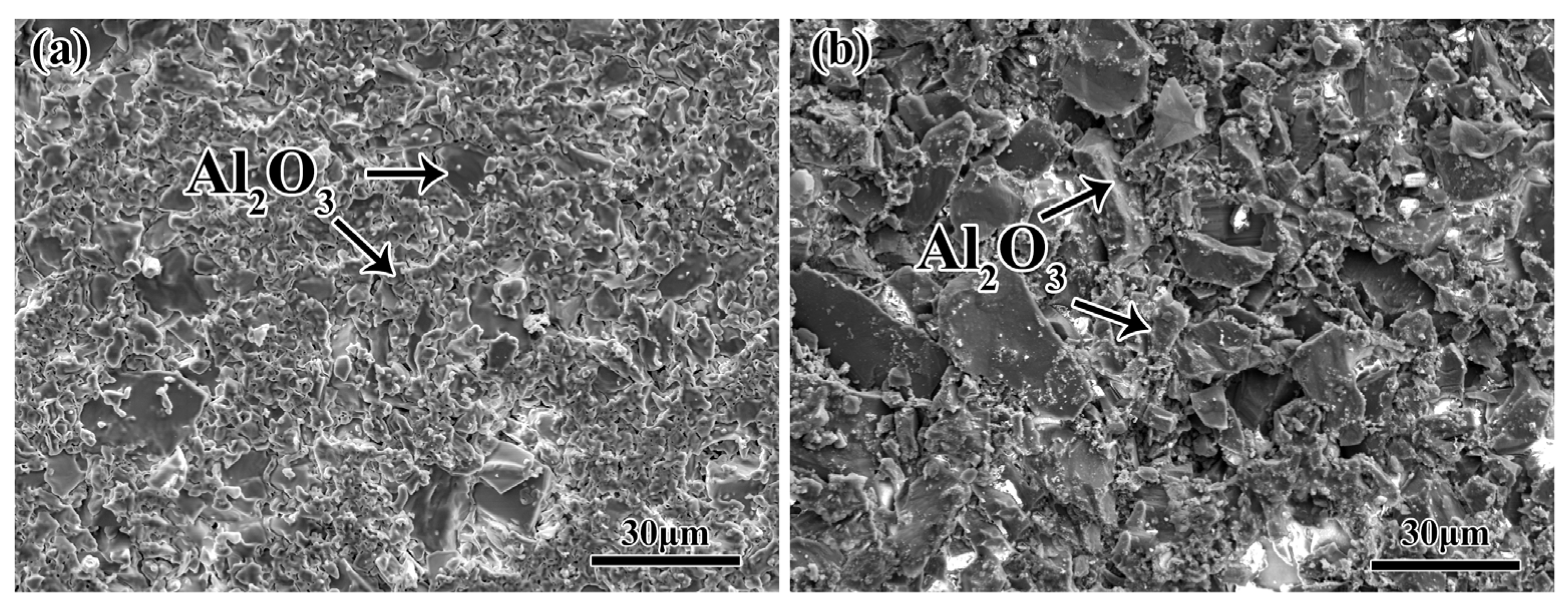
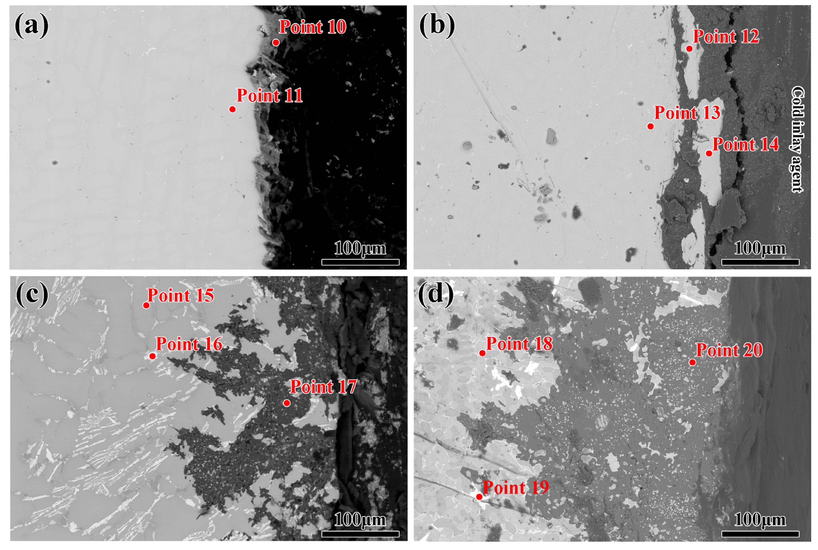
3.2. Microscopic Morphology of the Alloys Contacted with Al2O3 Shells

Figure 5 shows the SEM images of the bottom of the alloys contacted with the shells with kaolin and TiO2 additions at 1550 °C, respectively. From Figure 5a, it can be seen that a clear, thin layer of adhered sand could be observed on the bottom of the alloy after contacting the shell with the kaolin addition. A magnified image of area A in Figure 5a is shown in Figure 5b. It can be seen that the boundary between the alloy and the shell was clear, and the shell refractory was only adhering to the alloy without the appearance of penetration of the refractory. EDS results in Table 1 for points 1 and 2 indicated that the alloy (point 1) consisted of the alloy matrix with some attachment of Si elements. In addition, the shell refractory (point 2) consisted of Al and O elements, indicating that the face layer of Al2O3 shell was attached to the alloy. Figure 5c shows the same phenomenon as Figure 5a, indicating that the shell with TiO2 addition also exhibited good corrosion resistance to the alloy at 1550 °C. A magnified image of area B in Figure 5c is shown in Figure 5d. EDS results in Table 1 for point 3 and 4 indicated that the Al2O3 refractory were also attached to the alloy. Compared to the surface layer of the shell-added kaolin, the structure of the surface layer with added TiO2 appeared more dense and had distinct grain clusters. This suggested that a further sintering phenomenon occurred during the contact process with the alloy. Actually, the phenomenon of secondary sintering was not beneficial for the application of the shell, as it led to further adhesion of the shell to the alloy. Zan [24] demonstrated that TiO2 was a good aid for the sintering of Al2O3 refractory because Ti4+ ions could replace Al3+ ions in the lattice of Al2O3 refractory, resulting in the solid solution sintering effect.
Figure 6 shows the elemental mapping images for the bottom of the alloy. As shown in Figure 6a~b4, it can be seen that the attached shell refractory on the bottom of the alloy consisted of Al and O elements. Although Si was the constituent element of the shell refractory, it didn’t overlap with Al elements. It was mainly distributed along the bottom of the alloy, overlapping with Ni elements. The same phenomenon was also observed at the bottom of the alloy contacted with the shell with TiO2 addition.
Figure 7 shows the SEM images of the surface of the Al2O3 shell with kaolin and TiO2 additions, which was contacted with DD6 alloy melts. From Figure 7a, it can be seen that the surface of the shell with the kaolin addition consisted of some grains of small and large size. The structure of the surface was complete. From Figure 7b, it can be seen that only the large-sized grains were apparent at the surface of the shell with TiO2 addition. This indicates that the shell-added kaolin still contained numerous small-sized Al2O3 particles, and these small particles did not adhere to the alloy. This indicates that the kaolin addition resulted in better surface quality and corrosion resistance of the alloy melt.
When the contact temperature between the alloys and the shells was increased to 1600 °C, the phenomenon of sand adhesion significantly intensified. From Figure 8a, it can be seen that the bottom of the alloy contacted with the Al2O3 shell with kaolin addition exhibited a dense structure, and no naked alloy like Figure 4a appeared. It can be concluded that the interaction between them was more consequential because the increase in the alloy temperature could result in an increase in the activity of the alloy melt. A magnified image of area C in Figure 8a is shown in Figure 8b. It can be seen that the attached shell refractory exhibited a dense structure. The presence of a bright gray substance could be observed, and EDS results in Table 2 for point 5 and 6 indicate that this substance was the alloy. This indicates that the increase in the contact temperature not only promoted the increase in the thickness of the adhered layer but also facilitated the infiltration of the alloy melt towards the shell. This was because the fluidity of the alloy melt could be significantly increased at a higher temperature, intensifying the infiltration of the melt towards the shell. Then, the contact area between them was enhanced, consequently exacerbating the interaction. From Figure 8c, it can be seen that the bottom of the alloy contacted with the Al2O3 shell with TiO2 addition exhibited an uneven structure. By combining with the morphology in Figure 4d, it can be concluded that a large amount of shell refractory was attached to the bottom of the alloy. A magnified image of area D in Figure 8c is shown in Figure 8d. It can be seen that some small particles were observed in the attached layer. EDS results Table 2 for point 7 and 8 indicate that these particles consisted of Zr and O elements. Actually, ZrSiO4 powder was used during the preparation of the back layer of the Al2O3 shell. Thus, during the vacuum experiment, the decomposition of ZrSiO4 occurred, leading to the generation of the ZrO2 phase in the shell, due to the fact that ZrSiO4 was the raw material in the backing layer. However, it was found at the bottom of the alloy, indicating that the alloy melt had completely corroded the surface layer, thus reaching and entering the backing layer.
Figure 9 shows the SEM images (BSE mode) of the cross-section of the alloy contacted with Al2O3 shells with kaolin and TiO2 addition at 1550 °C and 1600 °C, respectively. From Figure 9a, it can be seen that the cross-section of the alloy was clear, and no significant refractory was attached to the alloy. However, there also existed a clear black layer, which could be found on the alloy side. EDS results in Table 3 for point 10 and 11 indicate that this layer was the attached layer, which was enriched with Si elements. Figure 9b shows the cross-section of the alloy contacted with the shell with TiO2 addition at 1550 °C. It can be seen that some cracks were apparent at the bottom of the alloy, resulting in the permeation of the alloy melt. This was due to the rapid contraction of the alloy during rapid cooling. Being different from Figure 9a, no black layer (segregation layer) was observed on the alloy side. However, the EDS results in Table 3 of points 12~14 indicate that some Ti elements were observable in the alloy. In addition, no Si elements appeared along the bottom of the alloy. In fact, the silica sol was used in the preparation of the Al2O3 shell; however, no Si diffusion was detected. This indicates that TiO2 addition in the shell could suppress the solid solution of Si elements in the alloy, and this phenomenon will require a more in-depth investigation in further study. When the contact temperature between the shell and the alloy was increased to 1600 °C, a significant interaction layer could be observed. Figure 9c shows the cross-section of the alloy contacted with the shell with kaolin addition at 1600 °C. It can be seen that an interaction layer with a 120 μm thickness could be observed in the alloy. The EDS results in Table 3 for point 15 and 16 shows the alloy matrix was distinguished from the interaction layer. The EDS result for point 17 indicates that the interaction layer was also Al2O3. Also, the alloy matrix (points 18~19) had a significant interaction with the shell with TiO2 addition at 1600 °C, leading to the appearance of a 220 μm thick interaction layer (point 20). Apparently, the interaction between the shell and the alloy only caused the attachment of Al2O3 refractory. A larger extent of interaction resulted in a larger corresponding adhesive layer. No other interaction product could be observed. Long revealed that the Ni-based superalloy had low chemical activity and did not easily chemically react with the Al2O3 shell [25]. Only the dissolution of the Al2O3 shell refractory could occur in the alloy melt, and it was consistent with the phase analysis in Figure 8 and Figure 9.
In order to further clarify the diffusion pattern of the constituent elements in Al2O3 shells, the elemental mapping analysis for the cross-section of the alloys in Figure 8 is shown in Figure 10. From Figure 10a,b, it can be seen that large amounts of Si elements were enriched in the alloy; however, no enrichment of Al elements was found. In fact, researchers had reported that the interaction between the Ni-based superalloy and the Al2O3 shell was dominated by physical dissolution–diffusion [26,27]. However, the dissolution extent of the elements was determined by the thermodynamic stability of the respective oxides. Apparently, due to the lower stability of SiO2 in comparison with Al2O3, the Si elements exhibited a prior dissolution in the alloy. Due to the lower stability of TiO2 in comparison with Al2O3, from Figure 10b–b4, it can be seen that no Al elements were enriched in the alloy. However, no Ti elements were also observed. It was because the dissolution extent of the Ti elements was larger than that of Si elements. Apparently, due to the increase in the interaction extent at 1600 °C, large amounts of Al elements were enriched in the alloy, as shown in Figure 10c,d. Additionally, the same enrichment phenomena of Si and Ti elements were also confirmed with the above analysis.

4. Conclusions

In this study, the interactions between DD6 alloys and Al2O3 shells with kaolin and TiO2 addition were investigated at 1550 °C and 1600 °C, respectively. Conclusions were obtained as follows:
(1)
At a contact temperature of 1550 °C, both Al2O3 shells with kaolin and TiO2 additions exhibited good corrosion resistance to DD6 alloys, although a thin shell refractory layer appeared at the bottom of the alloys and no penetration of the shell refractory was observed in the interior of the alloys.
(2)
When the contact temperature was increased to 1600 °C, a significant interaction occurred between Al2O3 shells with kaolin and TiO2 additions. Both shells exhibited noticeable damage at the contact interface. This indicates that the increase in temperature could significantly intensify the interaction between the shell and the alloy.
(3)
Additionally, the thicknesses of the sand adhesions on the shells with kaolin and TiO2 additions were 120 μm and 220 μm, respectively. Although the temperature of 1600 °C was not suitable for utilizing Al2O3 shells in preparing the DD6 alloy. However, compared to adding TiO2, the addition of kaolin could also enhance the stability of the Al2O3 shell. This study provides theoretical guidance for the systematic investigation of the effect of an additive on the interaction between the shell and alloy. Additionally, it offers a reference for the preparation of high-quality Ni-based alloys.

Author Contributions

Conceptualization, F.L.; methodology, C.L.; validation, G.C.; formal analysis, P.G., Z.C. and M.Z.; investigation, X.C. and Q.F.; resources, Y.L. and P.G.; data curation, Z.C., M.Z. and Y.L.; writing—original draft preparation, G.C.; writing—review and editing, X.H. and C.L.; visualization, X.C.; supervision, X.C. and F.L.; project administration, Q.F. and G.C.; funding acquisition, G.C., X.H., F.L. and C.L. All authors have read and agreed to the published version of the manuscript.

Funding

This research was funded by the National Natural Science Foundation of China (Contract: 52074183; 52104305; 52250091; 52174294; U2341267) and the National Key R&D Program of China, 2022YFB3404500.

Data Availability Statement

The original contributions presented in the study are included in the article, further inquiries can be directed to the corresponding author/s.

Conflicts of Interest

The authors declare no conflicts of interest.

References

  1. Satyanarayana, D.V.V.; Eswara, P.N. Nickel-based superalloys. In Aerospace Materials and Material Technologies; Aerospace Materials: Sunshine West, Victoria, 2017; Volume 1, pp. 199–228. [Google Scholar] [CrossRef]
  2. Xia, W.; Zhao, X.; Yue, L.; Zhang, Z. Microstructural evolution and creep mechanisms in Ni-based single crystal superalloys: A review. J. Alloys Compd. 2020, 819, 152954. [Google Scholar] [CrossRef]
  3. Caron, P. High y’solvus new generation nickel-based superalloys for single crystal turbine blade applications. Superalloys 2000, 2000, 737–746. [Google Scholar]
  4. Pollock, T.M.; Tin, S. Nickel-based superalloys for advanced turbine engines: Chemistry, microstructure and properties. J. Propuls. Power 2006, 22, 361–374. [Google Scholar] [CrossRef]
  5. Venkat, Y.; Choudary, K.R.; Chatterjee, D.; Das, D.K.; Pandey, A.K.; Singh, S. Development of mullite-alumina ceramic shells for precision investment casting of single-crystal high-pressure turbine blades. Ceram. Int. 2022, 48, 28199–28206. [Google Scholar] [CrossRef]
  6. Yao, J.S.; Dong, L.P.; Wu, Z.Q.; Wang, L.L.; Shen, B.; Yang, X.W. Interfacial Reaction Mechanism between Ceramic Mould and Single Crystal Superalloy for Manufacturing Turbine Blade. Materials 2022, 15, 5514. [Google Scholar] [CrossRef] [PubMed]
  7. Liu, L. The progress of investment casting of nickel-based superalloys. Foundry 2012, 11, 1273–1285. [Google Scholar]
  8. Wang, L.L.; Li, J.R.; Tang, D.Z.; Tang, D.Z.; Gu, G.H.; Li, X.; Yao, J.S.; Fan, H.N.; Niu, S.X. Effect of directional solidification condition on interfacial reaction between DD6 single crystal superalloy and zirconia-silica ceramic core. Adv. Mater. Res. 2014, 926, 72–76. [Google Scholar] [CrossRef]
  9. Li, J.R.; Zhong, Z.G.; Tang, D.Z.; Liu, S.Z.; Wei, P.; Wei, P.Y.; Wu, Z.T.; Huang, D.; Han, M. A Low-cost second geneution single crystal superalloy DD6. Superalloys 2000, 777–783. [Google Scholar]
  10. Kanyo, J.E.; Schafföner, S.; Uwanyuze, R.S.; Leary, K.S. An overview of ceramic molds for investment casting of nickel superalloys. J. Eur. Ceram. Soc. 2020, 40, 4955–4973. [Google Scholar] [CrossRef]
  11. Li, F.; Ni, H.J.; Yang, L.X.; Jiang, Y.; Wang, D.H.; Sun, B.D. Investigation of fused alumina based-mold facecoats for DZ22B directionally solidified blades. Materials 2019, 12, 606. [Google Scholar] [CrossRef]
  12. Zhao, Y.D.; Wang, L.Z.; Chen, C.Y.; Li, J.Q.; Li, X. Effect of a MgO–CaO–ZrO2-based refractory on the cleanliness of a K4169 Ni-based superalloy. Ceram. Int. 2023, 49, 117–125. [Google Scholar] [CrossRef]
  13. Wang, H.; Shang, G.F.; Liao, J.F.; Yang, B.; Yuan, C. Experimental investigations and thermodynamic calculations of the interface reactions between ceramic moulds and Ni-based single-crystal superalloys: Role of solubility of Y in the LaAlO3 phase. Ceram. Int. 2018, 44, 7667–7673. [Google Scholar] [CrossRef]
  14. Zi, Y.; Meng, J.; Zhang, C.W.; Yang, Y.H.; Zhou, Y.Z.; Ding, Y.T. Effect of Y content on interface reaction and wettability between a nickel-base single crystal superalloy melt and ceramic mould. J. Alloys Compd. 2019, 789, 472–484. [Google Scholar] [CrossRef]
  15. Wang, H.W.; Yang, J.X.; Meng, J.; Yang, Y.H.; Zhou, Y.Z. Wettability and interfacial reactions of a low Hf-containing nickel-based superalloy on Al2O3-based, SiO2-based, ZrSiO4, and CoAl2O4 substrates. Ceram. Int. 2020, 46, 22057–22066. [Google Scholar] [CrossRef]
  16. Wiśniewski, P. Polymer Binders of Ceramic Nanoparticles for Precision Casting of Nickel-Based Superalloys. Nanomaterials 2021, 11, 1714. [Google Scholar] [CrossRef] [PubMed]
  17. Jones, S.; Yuan, C. Advances in shell moulding for investment casting. J. Mater. Process. Technol. 2003, 135, 258–265. [Google Scholar] [CrossRef]
  18. Fan, J.X.; Fan, H.N.; Song, Z.; Guo, Y.J.; Li, M.M.; Li, X.; Qi, C.J.; Xu, X.Q. Thermal-shock stable Al2O3 crucible for superalloy smelting through slip casting with particle gradation. Ceram. Int. 2023, 49, 8762–8771. [Google Scholar] [CrossRef]
  19. Tamta, K.; Karunakar Benny, D. Enhancing mechanical properties and permeability of ceramic shell in investment casting process. Mater. Manuf. Process. 2018, 34, 612–623. [Google Scholar] [CrossRef]
  20. Zhu, L.; Dong, Y.C.; Li, L.L.; Liu, J.; You, S.J. Coal fly ash industrial waste recycling for fabrication of mullite-whisker-structured porous ceramic membrane supports. RSC Adv. 2015, 5, 11163–11174. [Google Scholar] [CrossRef]
  21. Zhu, W.Y.; Liu, Y.; Guan, K.; Peng, C.; Wu, J.Q. Preparation of ZrO2 fiber modified Al2O3 membrane supports with enhanced strength and permeability. J. Eur. Ceram. Soc. 2019, 39, 1712–1716. [Google Scholar] [CrossRef]
  22. Jansson, S.; Brabie, V.; Jönsson, P. Corrosion mechanism of commercial MgO–C refractories in contact with different gas atmospheres. ISIJ Int. 2008, 48, 760–767. [Google Scholar] [CrossRef]
  23. Liu, Y.S.; Gao, Y.Y.; Wang, E.H.; Chen, G.Y.; Xu, E.X.; Zhao, F.; Zhao, Y.S.; Li, C.H.; Hou, X.M. Interaction between CA6-MA crucible and molten wrought Ni-based superalloys. J. Eur. Ceram. Soc. 2023, 43, 1714–1722. [Google Scholar] [CrossRef]
  24. Zan, Y. Influence of TiO2 on Chemical Stability, High Temperature and Electrochemical Properties of Alumina Ceramics based on η-Al2O3. Int. J. Electrochem. Sci. 2021, 16, 210822. [Google Scholar] [CrossRef]
  25. Samal, S.; Blanco, I. Investigation of Dispersion, Interfacial Adhesion of Isotropic and Anisotropic Filler in Polymer Composite. Appl. Sci. 2021, 11, 8561. [Google Scholar] [CrossRef]
  26. Long, X.; Liu, L.; Yu, H.; Yang, W. Interfacial Reaction between DZ22B Superalloy and Al2O3 Ceramic Mold Shell for Investment Casting. Spec. Cast. Nonferrous Alloys 2018, 38, 525–528. [Google Scholar] [CrossRef]
  27. Dyamant, I.; Itzhak, D.; Hormadaly, J. Thermal properties and glass formation in the SiO2–B2O3–Bi2O3–ZnO quaternary system. J. Non-Cryst. Solids 2005, 351, 3503–3507. [Google Scholar] [CrossRef]
Figure 1. The schematic diagram of contact experiment apparatus.
Metals 14 00164 g001
Figure 2. Macroscopic images of the alloys located on Al2O3 shells with kaolin and TiO2 additions at 1550 °C and 1600 °C, respectively: (a) kaolin addition at 1550 °C; (b) TiO2 addition at 1550 °C; (c) kaolin addition at 1600 °C; (d) TiO2 addition at 1600 °C.
Metals 14 00164 g002
Figure 3. The macroscopic pictures of the bottom of the alloys contacted with Al2O3 shells with kaolin and TiO2 additions at 1550 °C and 1600 °C, respectively: (a) kaolin addition at 1550 °C; (b) TiO2 addition at 1550 °C; (c) kaolin addition at 1600 °C; (d) TiO2 addition at 1600 °C.
Metals 14 00164 g003
Figure 4. Macroscopic images of the surface of Al2O3 shells with kaolin and TiO2 additions contacted with the alloys at 1550 °C and 1600 °C, respectively: (a) kaolin addition at 1550 °C; (b) TiO2 addition at 1550 °C; (c) kaolin addition at 1600 °C; (d) TiO2 addition at 1600 °C.
Metals 14 00164 g004
Figure 5. SEM images of the bottom of the alloys contacted with Al2O3 shells with kaolin and TiO2 additions at 1550 °C, respectively: (a) with kaolin addition; (b) magnified image of area A in Figure 4a; (c) with TiO2 addition; (d) magnified image of area B in Figure 4c.
Metals 14 00164 g005
Figure 6. EDS elemental mapping pictures of O, Ni, Al, and Si: (a) the bottom of the alloy contacted with the shell with kaolin addition at 1550 °C; (b) the bottom of the alloy contacted with the shell with TiO2 addition at 1550 °C.
Metals 14 00164 g006
Figure 7. SEM images of the bottom of the alloys contacted with Al2O3 shells with kaolin and TiO2 additions at 1550 °C, respectively: (a) kaolin addition; (b) TiO2 addition.
Metals 14 00164 g007
Figure 8. SEM images of the bottom of the alloys contacted with Al2O3 shells with kaolin and TiO2 additions at 1600 °C, respectively: (a) kaolin addition; (b) magnified image of area C in (a); (c) with TiO2 addition; (d) magnified image of area D in (c).
Metals 14 00164 g008
Figure 9. SEM images of the cross-section of the alloys contacted with Al2O3 shells with kaolin and TiO2 additions at 1550 °C and 1600 °C, respectively; (a) with kaolin addition at 1550 °C; (b) with TiO2 addition at 1550 °C; (c) with kaolin addition at 1600 °C; (d) with TiO2 addition at 1600 °C.
Metals 14 00164 g009
Figure 10. (ad) The combination of all elements for the cross-section of the alloys contacted with Al2O3 shells with kaolin and TiO2 additions at 1550 °C and 1600 °C, respectively; (a1d4) the EDS element mapping pictures for O, Al, Zr, Ba, Ti, Cr, Co, Ni, Hf, W, and Re elements.
Metals 14 00164 g010
Table 1. EDS results of point 1~4.
PointElement/at%
AlOSiNiTi
120.1512.3215.7757.87/
262.1037.79/00.11/
321.3207.9012.7058.08/
449.6350.18/00.18/
Table 2. EDS results of points 5~9.
PointElement/at%
AlOSiNiTiZr
527.0106.6717.3948.94//
641.6738.2621.06///
7/54.08///45.92
8/34.85///65.15
947.6837.0715.25///
Table 3. EDS results of points 10~20.
PointElement/at%
AlOSiNiTiNb, Mo, Cr.
106.66/7.6248.50/Bal.
1114.65//65.12/Bal.
1215.21//63.710.11Bal.
1313.55//64.800.13Bal.
1415.44//63.730.08Bal.
1512.70/0.3244.03/Bal.
16/// /Bal.
1728.7257.2912.921.07/Bal.
1828.45/2.4061.12/Bal.
1914.93/5.3164.46/Bal.
2033.9455.4410.61//Bal.
Disclaimer/Publisher’s Note: The statements, opinions and data contained in all publications are solely those of the individual author(s) and contributor(s) and not of MDPI and/or the editor(s). MDPI and/or the editor(s) disclaim responsibility for any injury to people or property resulting from any ideas, methods, instructions or products referred to in the content.

