Article

Effects of HIP on Microstructure and Mechanical Properties of LMD Fe36Mn21Cr1815NiAl10 High-Entropy Alloy

School of Materials Science and Engineering, Harbin Institute of Technology, Harbin 150001, China
*
Author to whom correspondence should be addressed.
Metals 2024, 14(12), 1452; https://doi.org/10.3390/met14121452
Submission received: 6 November 2024 / Revised: 12 December 2024 / Accepted: 16 December 2024 / Published: 18 December 2024

Abstract

:
To reduce costs, a cobalt-free FeMnCrNi-based HEA has been proposed. Further investigation into the mechanical properties of the Fe36Mn21Cr18Ni15Al10 alloy is essential to expand its application potential. In this study, a cobalt-free Fe36Mn21Cr18Ni15Al10 HEA was fabricated using LMD, and the effects of HIP on its microstructure and mechanical properties were investigated. Results indicated that the as-printed specimen exhibited a dual-phase structure consisting of BCC and FCC phases, with the B2 phase dispersed as fine blocks. After HIP treatment, the content of the FCC phase significantly increased, displaying a lamellar distribution between the BCC phases, with secondary block-like B2 phases forming within the BCC matrix. The HIP process enhanced the density of the high-entropy alloy to 98.2%, while the tensile strength at 25 °C increased to 903.9 MPa. Additionally, the post-fracture elongation improved to 17.4%, thereby increasing the potential for industrial applications of HEAs.

1. Introduction

The concept of high-entropy alloys (HEAs) was first introduced by materials scientist Jien-Wei Yeh and colleagues in 2004 [1], sparking widespread research interest due to their distinctive structural properties. Unlike conventional alloys, which are typically based on a single principal element with minor additions of other elements to enhance performance, high-entropy alloys deviate from this conventional approach. They consist of five or more metallic elements in equiatomic or near-equiatomic ratios, with the molar fraction of each element typically ranging from 5% to 35%. The intricate mixing of multiple elements imparts high-entropy alloys with exceptional and well-balanced properties [2,3,4,5].
High-entropy alloys (HEAs) have attracted substantial research interest in their preparation and heat treatment processes. Research indicates that in AlxCoCrFeNi HEAs fabricated via Directed Laser Fabrication (DLF), an increase in aluminum content results in a transition from a dual-phase FCC + BCC to a single BCC phase [6,7,8]. Conversely, FeCoCrNi HEAs, prepared using Selective Laser Melting (SLM), display a single-phase FCC solid solution structure, possessing a yield strength of up to 600 MPa [9,10,11]. Following SLM, Hot Isostatic Pressing (HIP) has demonstrated improvements in densification and tensile strength in CoCrFeMnNi HEAs [12]. However, these studies often focus on Ni- and Co-rich HEAs, incurring high costs. An increasing interest exists in the development of cost-effective, Co-free HEAs, with several studies reporting unique structures and compositions exhibiting excellent mechanical properties [13,14,15,16,17]. However, research on Co-free HEAs fabricated by Laser Metal Deposition (LMD) remains limited.
HIP, renowned for its pore reduction and material densification through high temperature and pressure, has been extensively studied for its effects on metallic materials [18]. HIP has enhanced the intermediate-temperature ductility of nickel-based superalloys from 6.4% to 9.3% without compromising yield strength [19]. Furthermore, HIP has proven effective in mitigating microvoid formation in TiAl alloys, leading to enhanced mechanical properties [20]. However, the effects of HIP on the microstructure and properties of High-Entropy Alloys (HEAs), particularly phase composition and microstructural changes post-HIP, remain underexplored.
Furthermore, due to the low ductility of many high-entropy alloys, tensile testing exhibits a higher sensitivity to crack propagation, leading to the characterization of mechanical properties in many reports being derived from compressive performance [21,22,23,24,25]. However, tensile testing provides a more accurate reflection of the true mechanical behavior of the alloy. It is essential to comprehensively understand the effects of HIP on microstructure and phase composition, as well as its influence on subsequent tensile properties and strengthening mechanisms, in order to facilitate the further development of these novel materials for structural applications.
This study centers on the Fe36Mn21Cr18NiAl10 high-entropy alloy system, developed during the investigation of cobalt-free high-entropy alloys, and establishes a control group subsequent to LMD and HIP. The objective of this research is to examine the effects of HIP on the phase composition, microstructure, and mechanical properties of high-entropy alloys, particularly regarding the relationship between variations in phase composition and mechanical performance.

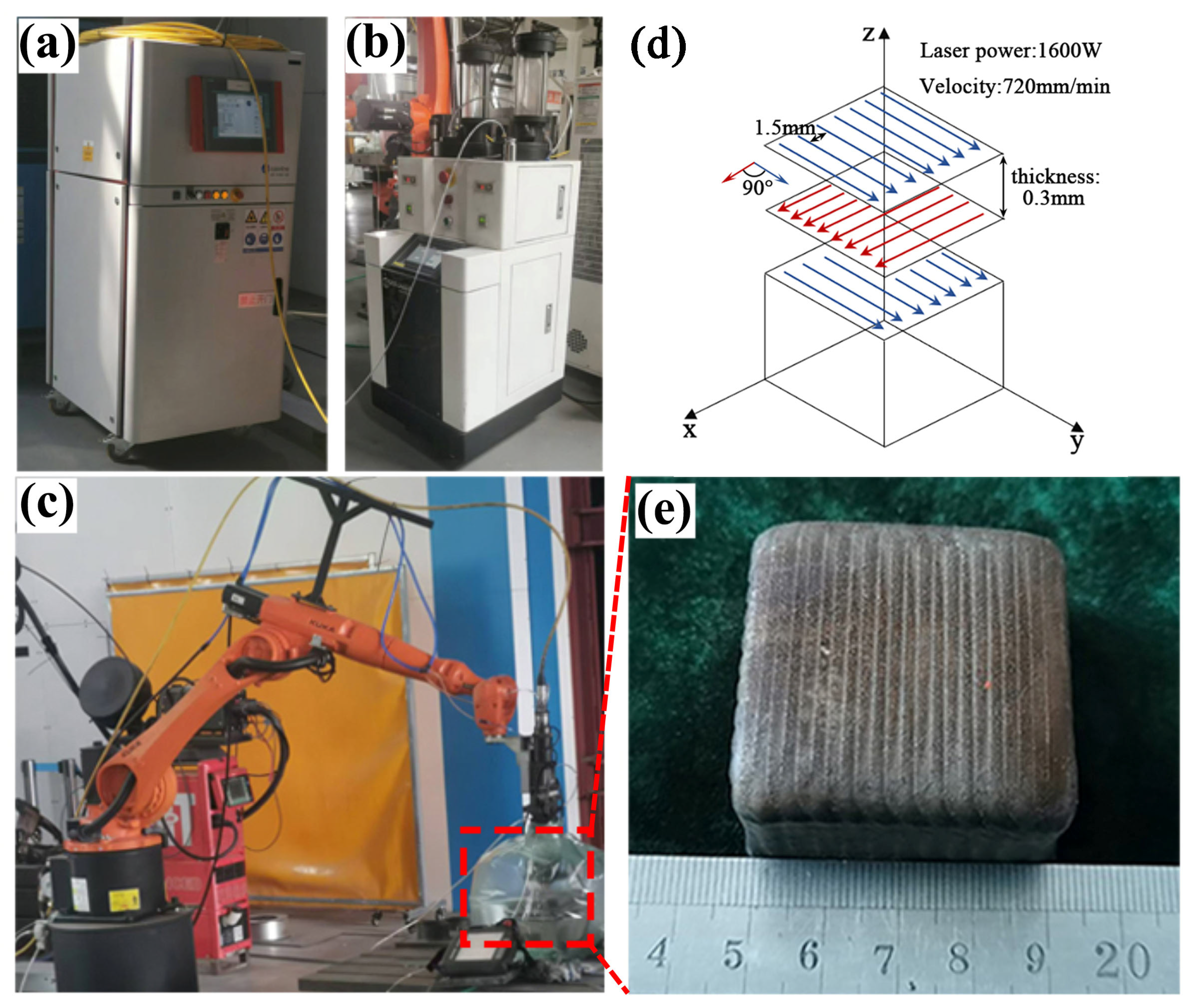
2. Materials and Methods

A high-entropy alloy powder with a nominal composition of Fe36Mn21Cr18NiAl10 was synthesized using a vacuum inert gas atomization technique. Each raw material exhibited a purity greater than 99.9 wt%. Figure 1a,b depicts the microstructural morphology of the powder. The majority of the powder is characterized by a regular spherical or near-spherical shape, with a minor quantity of elongated particles present, as well as a few satellite particles adhering to the surface. The microstructure of the powder is predominantly dendritic. Figure 1c illustrates the particle size distribution of the powder, which predominantly falls within the range of 45~105 μm. The distribution is more concentrated in the particle size range of 50~80 μm, with Dv(10), Dv(50), and Dv(90) values of 51.7 μm, 61.4 μm, and 86.5 μm, respectively.
Figure 1d presents the XRD analysis results for the HEA powder. The phase composition of the HEA powder indicates a dual-phase structure consisting of BCC and FCC phases. The XRD pattern exhibits a total of four diffraction peaks, with the peak corresponding to the (110) crystal plane of the BCC phase being the most intense, located at approximately 44°.
A KUKA KR60L30 (KUKA Robot GmbH, Augsburg, Bavaria, Germany) laser was utilized to fabricate an HEA bulk sample measuring 40 mm × 40 mm × 20 mm on a GH4169 substrate (Shenyang Zhongke Yucheng Technology Co., Ltd., Shenyang, China) via the LMD technique, under the following conditions: a laser power of 1600 W, a scanning speed of 720 mm/min, a layer thickness of 0.3 mm, a spot diameter of 3.5 mm, and a scanning distance of 3 mm. During the preparation process, the substrate was first preheated to 200 °C, with argon gas continuously supplied at a flow rate of 0.45 L/min to maintain an inert gas atmosphere. Upon completion of the fabrication process, the sample was subjected to air cooling. Figure 2 illustrates a schematic of the LMD printing process. The samples underwent HIP treatment as outlined in Table 1, followed by cooling in a furnace. As depicted in Figure 2d, the schematic diagram of the LMD process is provided. For each printed layer, the scanning direction is rotated by 90°, and a cooling period of 3 min is applied between layers. The post-printing specimen, shown in Figure 2e, exhibits no defects such as unmelted regions, pores, or cracks, thereby indicating a high-quality formation.
To mitigate the influence of the surface heat-affected zone, samples designated for structural characterization, residual stress measurement, and mechanical performance testing were extracted from the interior of the material. The samples comprised cubes measuring 10 mm × 10 mm × 10 mm and plate tensile specimens with a gauge length of 15 mm, a width of 2 mm, and a thickness of 2 mm. The samples were subsequently polished sequentially using sandpaper with grits ranging from 80# to 5000# to attain a smooth testing surface and then polished with a diamond polishing compound. The phase structure of the samples was analyzed using a APD-10 (Leeman, Beijing, China) X-ray diffraction (XRD) apparatus, employing a Cu-Kα1 X-ray source (wavelength of 1.5406 Å) and scanning over a 2θ range of 10° to 100° at a scanning rate of 2°/min. The powder particle size distribution and specimen density were determined using Image-J (1.8.0). Image-J was utilized to calculate the porosity fraction of cross-sectional areas at equidistant intervals along the longitudinal axis of the printed specimens, under varying processing parameters. The average value of these measurements was then computed to determine the overall porosity of the sample. A HITACHI SU5000 (Tokyo, Japan) scanning electron microscope (SEM), equipped with an energy-dispersive spectrometer (EDS), was utilized to examine the microstructure, fracture morphology, and elemental composition. Tensile tests were performed at room temperature using an electronic universal testing machine and at 300 °C with a high-temperature tensile testing machine, at a strain rate of 5 × 10⁻⁴ s−1. All tensile tests were repeated a minimum of three times to ensure the reliability of the results. The powder particle size distribution and sample density were analyzed using Image-J software.

3. Results and Discussion
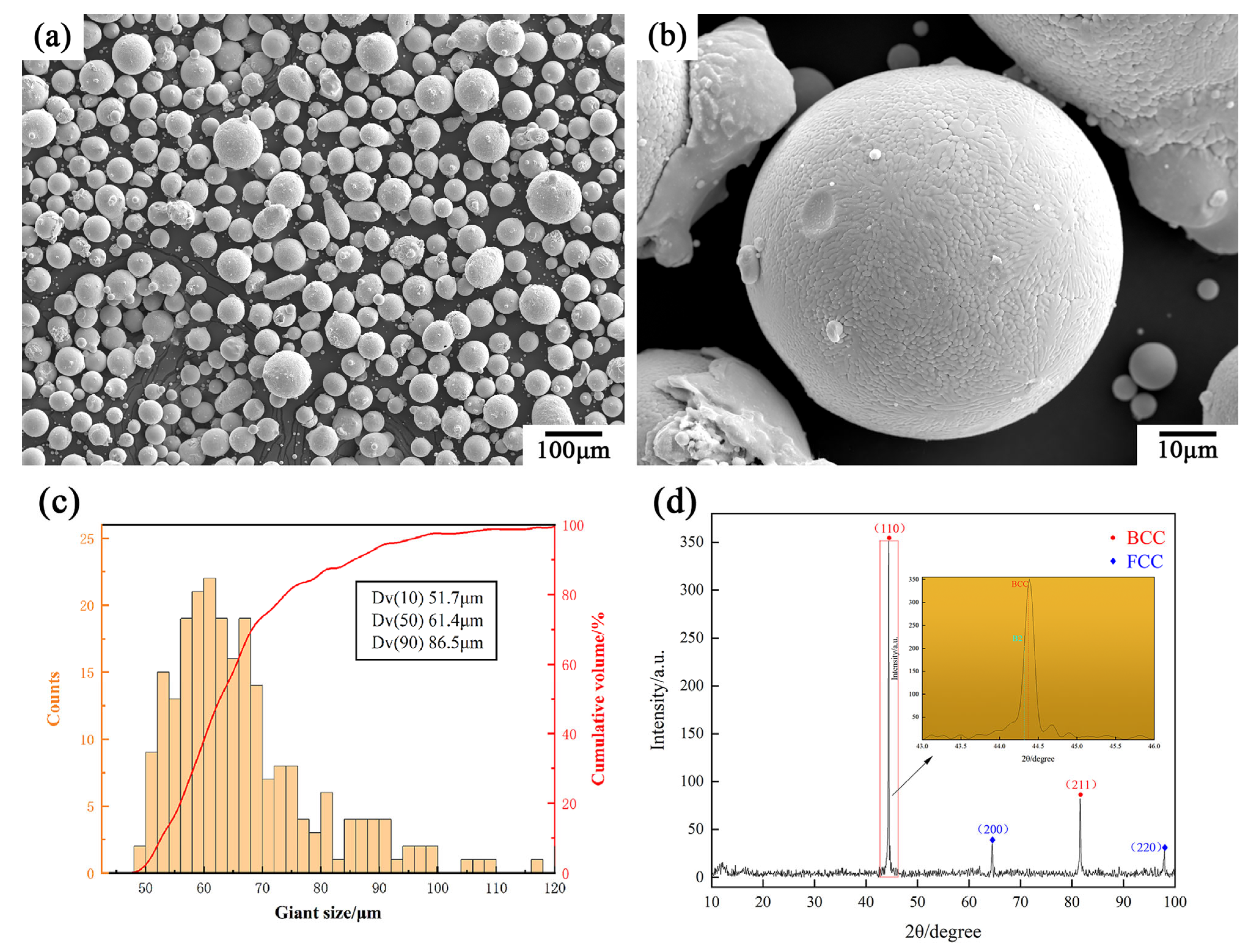
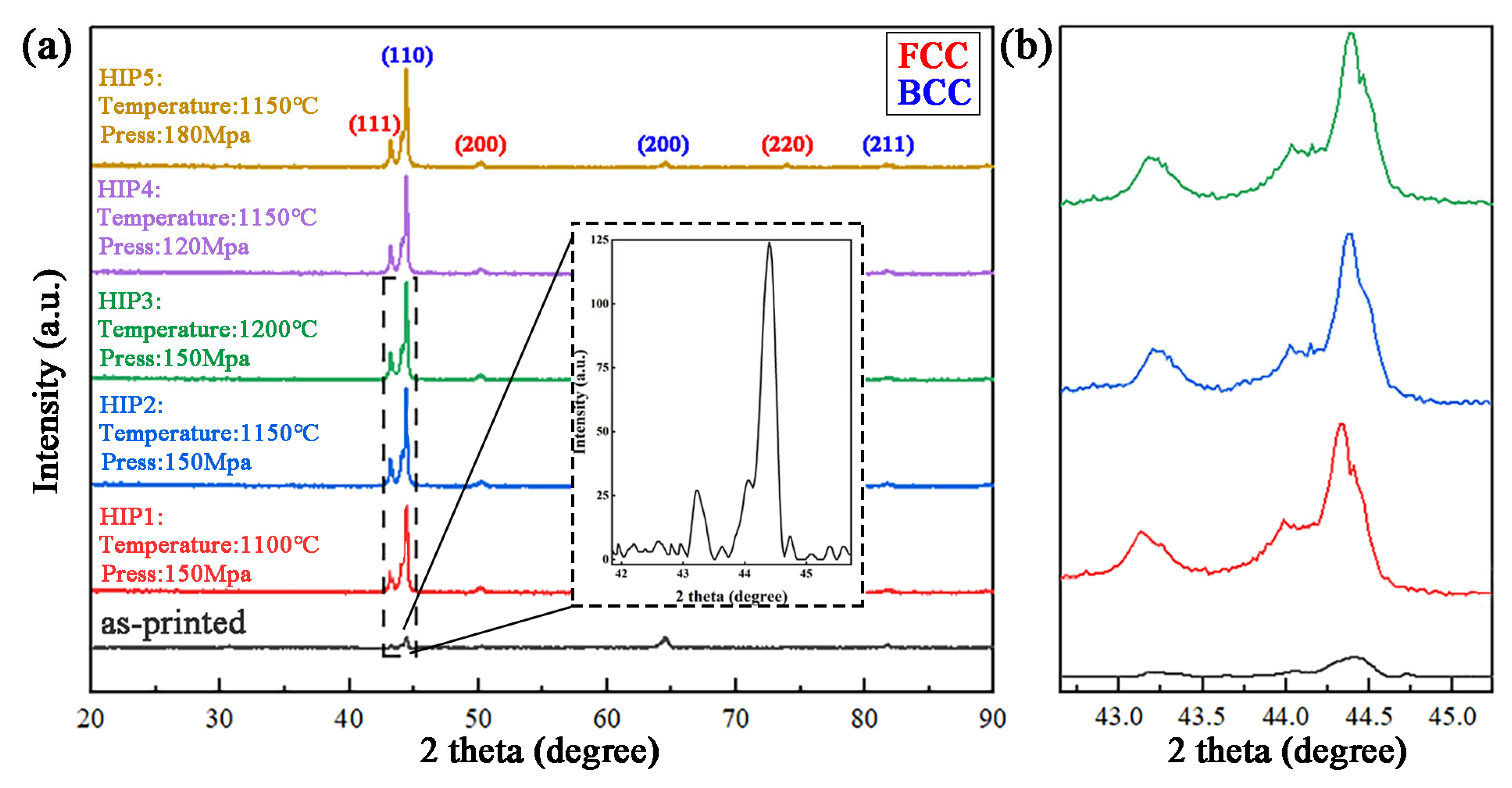
3.1. Phase Analysis

The XRD patterns of the specimens produced by LMD and HIP are presented in Figure 3. The crystal structure of the as-printed specimens exhibits a dual-phase structure composed of FCC and BCC phases, with the BCC phase further classified into BCC1 and B2 phases, consistent with prior research findings [26,27,28,29,30]. The diffraction peaks for the as-printed specimens primarily appear at 44.4° and 64.4°, with an additional (200)fcc diffraction peak observed at 50.1° in comparison to the HEA powder. In contrast to the as-printed specimens, the diffraction peaks for the HIPed specimens demonstrate a tendency to shift to lower angles, with a pronounced peak at 44.4°, indicating an enhanced degree of grain orientation along the (110)bcc direction. Figure 3b presents an enlarged view of the XRD pattern, indicating that, as the HIP temperature increases, the diffraction peaks gradually shift to the right. This shift is attributed to the recrystallization of the HEA samples resulting from increased thermal input, leading to lattice distortion under elevated temperature and pressure, consequently resulting in a decrease in the lattice constant. Conversely, varying the HIP pressure has a negligible effect on the phase composition.
The type of solid solution phases present in an alloy can be predicted using the valence electron concentration (VEC). Specifically, alloys with a VEC ≤ 6.87 are more likely to form a BCC phase [31]. Alloys with a VEC between 6.87 and 8.00 tend to exhibit a dual-phase structure consisting of both FCC and BCC phases, while alloys with a VEC ≥ 8.00 are more likely to form an FCC phase [32,33,34]. The average VEC for the Fe36Mn21Cr18Ni15Al10 high-entropy alloy was calculated using the following formula:
V E C = i n c i × V E C i
where ci denotes the molar fraction of each element and VECi represents the valence electron count of that element. From this calculation, the VEC of this HEA was determined to be approximately 7.23. Consequently, the XRD experimental results align with the phase structure predicted by the VEC.

3.2. Structure Analysis

Figure 4 shows the density and microstructure of different HEA samples. The as-printed specimen surface contained numerous irregularly distributed microcracks, pores, and other defects, primarily due to splashing from the melt pool and residual gasses within the melt. In comparison, the HIPed specimen displayed fewer pores, with significantly reduced porosity. The density, calculated using Image-J software, for the HIPed specimens was 96.7%, 98.2%, 97.4%, 96.2%, and 97.7%, respectively (the as-printed specimen’s density was 93.4%), indicating that HIP significantly improves the specimen’s density.
During the HIP process, the printed specimen is subjected to uniform triaxial pressure at elevated temperatures, which facilitates the closure of pores under compression. When the temperature reaches 1150 °C and the pressure reaches 150 MPa, the specimen achieves the highest density, reaching 98.2%. Simultaneously, the average equivalent circle diameter (AECD) of the pores decreases from 36.2 μm to 3.4 μm. As the temperature continues to rise to 1200 °C, the sample density slightly decreases, likely due to the onset of tissue stress from excessive temperature, which impedes further pore closure. The pore analysis results of the low-pressure sample (HIP4) indicate that pressure plays a significant role in enhancing the sample density. Appropriate pressure promotes the compression of pores, microcracks, and other voids within the material. When the pressure is increased to 180 MPa (HIP5), the pores are effectively eliminated by the greater equiaxed pressure, resulting in an increase in density to 97.7%. However, it is important to note that this conclusion is based on metallographic images and calculations performed using Image-J software. Compared to methods such as industrial CT scanning, this approach has certain limitations.
Figure 5 presents the microstructure of the as-printed and HIP2 specimens. The SEM image in Figure 5a reveals the microstructure of the as-printed specimen, which exhibits dendritic structures aligned along the build direction, showing pronounced epitaxial growth characteristics. Bright, needle-like (lamellar) precipitates are irregularly distributed near grain boundaries and within grains, while pores of varying sizes are uniformly dispersed at phase boundaries and within the phases. A few microcracks were also observed. The magnified view of Figure 5a reveals fine, gray, blocky phases uniformly distributed in the dark-field matrix. The SEM image in Figure 5b depicts the microstructure of the HIP2 specimen, where the post-HIP microstructure clearly displays alternating bright and dark regions, with bright bands irregularly distributed within the dark matrix. The enlarged view of Figure 5c reveals blocky precipitates within the dark regions. A comparison of the HIP2 and as-printed images indicates that, after HIP, the pores and microcracks were significantly reduced, the bright phase had grown under high temperature and pressure and was diffusely distributed, while the fine blocky precipitates showed a decrease in density and an increase in size, with some forming a “butterfly-like” distribution. Based on the current research, it is preliminarily inferred that the bright phase corresponds to the FCC phase, the dark phase to the BCC phase, and the blocky phase to the B2 phase [35,36,37,38].
Figure 5c–f displays the microstructures of HIP1, HIP3, HIP4, and HIP5 specimens, respectively. A comparison with Figure 5b indicates that the microstructural morphology of HIPed specimens is similar under various HIP parameters. For HIP1, due to the relatively low heat treatment temperature, microcracks were not fully closed. In contrast, HIP3 reveals the presence of impurities within the microstructure due to the higher thermal input. Figure 5e,f demonstrates that pressure variations resulted in continuous transgranular pores within the microstructure, with these defects appearing exclusively inside the B2 phase.
To assess the influence of HIP on the elemental distribution in HEAs, surface scans by EDS were conducted on both the as-printed and HIP2 specimens, as illustrated in Figure 6 and Figure 7. During the LMD process, rapid cooling induced the preferential formation of the BCC phase, which demonstrates superior stability at elevated temperatures due to its comparatively lower free energy. HIP treatment facilitated the growth of the FCC phase, resulting in a marked expansion of the FCC phase. Furthermore, the increased temperature during HIP treatment facilitated the precipitation of an Al- and Ni-rich B2 phase (ordered BCC) resulting from elemental diffusion within the BCC matrix. Notably, the Mn distribution remained relatively uniform in both the as-printed and HIPed specimens, which aligns with prior studies [39,40,41,42].
Point scans by EDS were performed on different regions within the microstructure, and the results are presented in Table 2. Based on the combined analysis of XRD and EDS results, it was determined that the needle-like precipitates in the microstructure of the as-printed specimen correspond to an Fe- and Ni-rich FCC phase. In the HIPed specimen, the bright regions represent the FCC phase, which has grown from the needle-like precipitates, while the dark regions correspond to an Fe- and Cr-rich BCC1 phase. The blocky precipitates were identified as an Al- and Ni-rich B2 phase. Notably, the distribution of Mn was relatively uniform across all phases.

3.3. Tensile Properties and Analysis of Fracture Morphology

Figure 8a presents representative engineering stress–strain curves for the tensile samples at room temperature. The tensile elongation (εf) is lower due to the presence of holes and microcracks in the as-printed HEA samples; these defects serve as a source of cracks in the tensile specimen, leading to premature fracture. In comparison to the as-printed HEA samples, the HIPed samples exhibit higher ultimate strength (σUTS) and εf, with σUTS reaching 903.9 MPa and εf reaching 17.4%. This indicates that the HIP treatment has resulted in the closure of holes and microcracks within the specimens and a denser microstructure. A comparison of different HIP processes reveals that, as the HIP temperature increases, εf gradually increases while σUTS gradually decreases. In contrast, variations in pressure decrease both εf and σUTS.
Figure 8b presents representative engineering stress–strain curves for the tensile samples at 300 °C. The trend of the tensile sample curves is similar to that observed at room temperature; the σUTS of the HIPed HEA sample reaches 800.7 MPa, and the εf reaches 20.5%, representing a significant increase compared to the as-printed HEA sample. However, due to the recovery of the cellular structure following the high-temperature treatment, the dislocation density was reduced, resulting in a lower yield strength (σy) compared to that of the as-printed HEA sample. Compared to room temperature, the elongation of the specimens at 300 °C increased, while the σUTS decreased. The σy, σUTS, and εf of the specimens produced by LMD and heated by HIP are presented in Table 3.
Figure 9 illustrates the SEM morphology of the tensile fracture cross-section of the high-entropy alloy. Figure 9a,b displays the tensile fracture morphology of the aforementioned high-entropy alloy at room temperature following LMD and HIP treatment. A comparison reveals that the fracture region of the as-printed high-entropy alloy is relatively flat. Obvious cleavage river patterns and cleavage steps are also observed, indicating that the primary fracture mechanism of the material is cleavage fracture, manifested as transgranular fracture. Inherent defects, such as pores and cracks, act as stress concentration sites. Under the influence of tensile stress, these defects facilitate the rapid propagation of cracks, ultimately leading to brittle fracture [43,44,45,46,47,48,49]. Following HIP treatment, the fracture mechanism evolves to a coexistence of cleavage and tough fractures. Dimples are observed on the fracture surface, in addition to the cleavage river patterns and cleavage steps, indicating that the high-entropy alloy exhibits a certain degree of tensile plasticity after HIP treatment. During the stretching process, the lattice within the material begins to slip, generating dislocations and inducing localized deformation. These deformations result in relative displacement between grains, which increases the deformation area and gradually raises the stress in localized regions. As plastic deformation progresses, microcracks form at sites of high internal stress, and their growth continues, ultimately leading to fracture [50,51,52].
Figure 9c,d displays the tensile fracture morphology of the aforementioned high-entropy alloys following LMD and HIP treatment at 300 °C. A comparison indicates that the fracture morphology of the as-printed high-entropy alloy exhibits cleavage river patterns, cleavage steps, and features a small number of dimples, with brittle fracture being dominant. The fracture mechanism is characterized by both cleavage and tough fractures; however, microcracks are clearly observed at the fracture interface. The stress concentration caused by these microcracks is the primary reason for the premature fracture of the as-printed specimens, and the fracture morphology of the HIPed specimens resembles that of the as-printed specimens. The high-temperature fracture morphology of the HIPed specimen differs significantly from that of the as-printed specimen. A large number of dimples are observed on the fracture surface, with their size being finer than that observed at room temperature. A small number of brittle fractures are also present, with an enlarged view of these brittle fractures displayed in the upper right of Figure 9d. It is evident that hot isostatic pressing mitigates microcracks within the material, alleviates internal stress concentration, enhances the density of high-entropy alloys, and improves fracture toughness.

4. Conclusions

In conclusion, this paper employed various HIP process parameters to treat as-printed high-entropy alloys, examining the effects of HIP parameters on the organization and properties of the printed high-entropy alloys through characterization methods including XRD, SEM, and EDS:
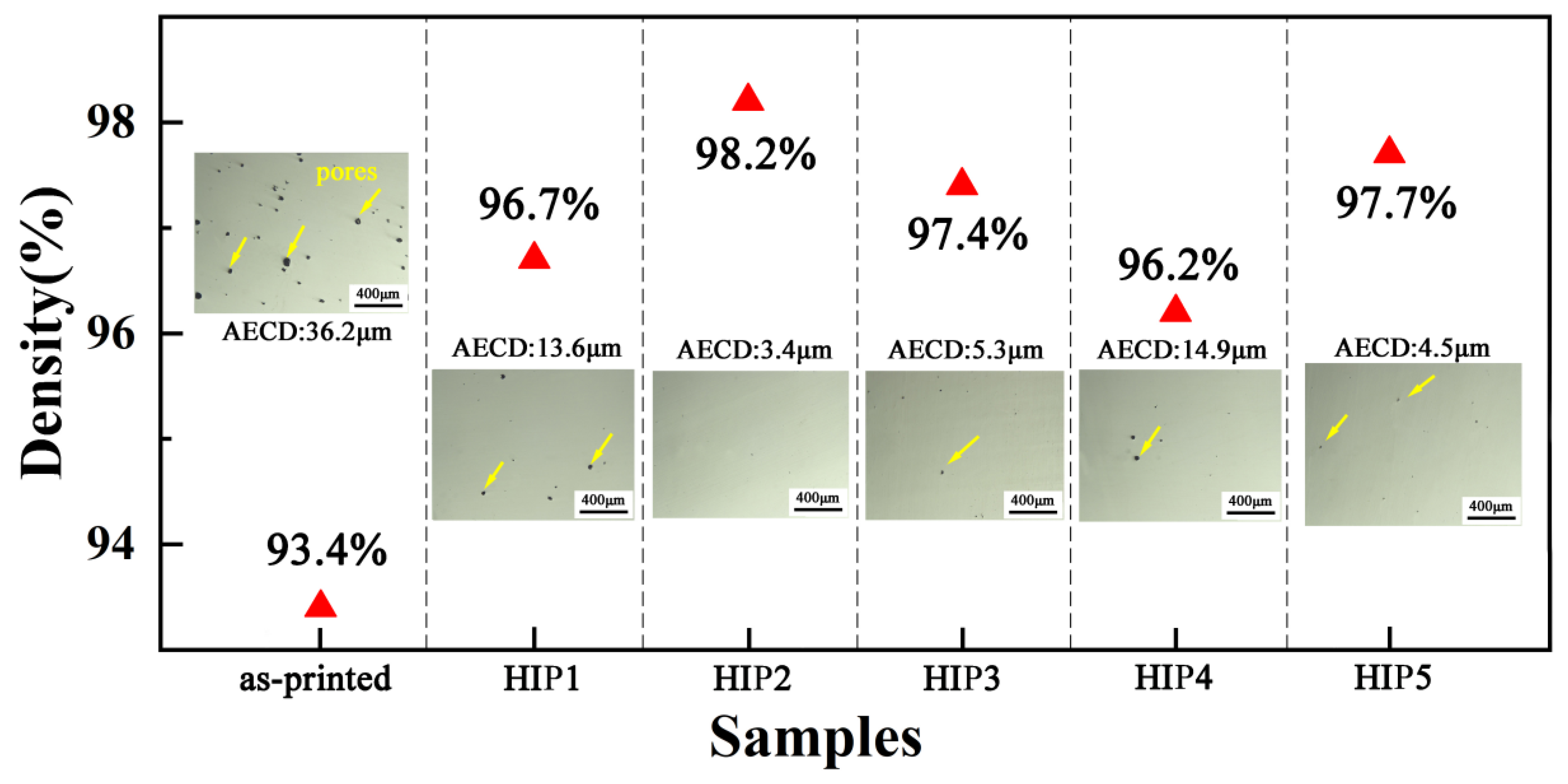
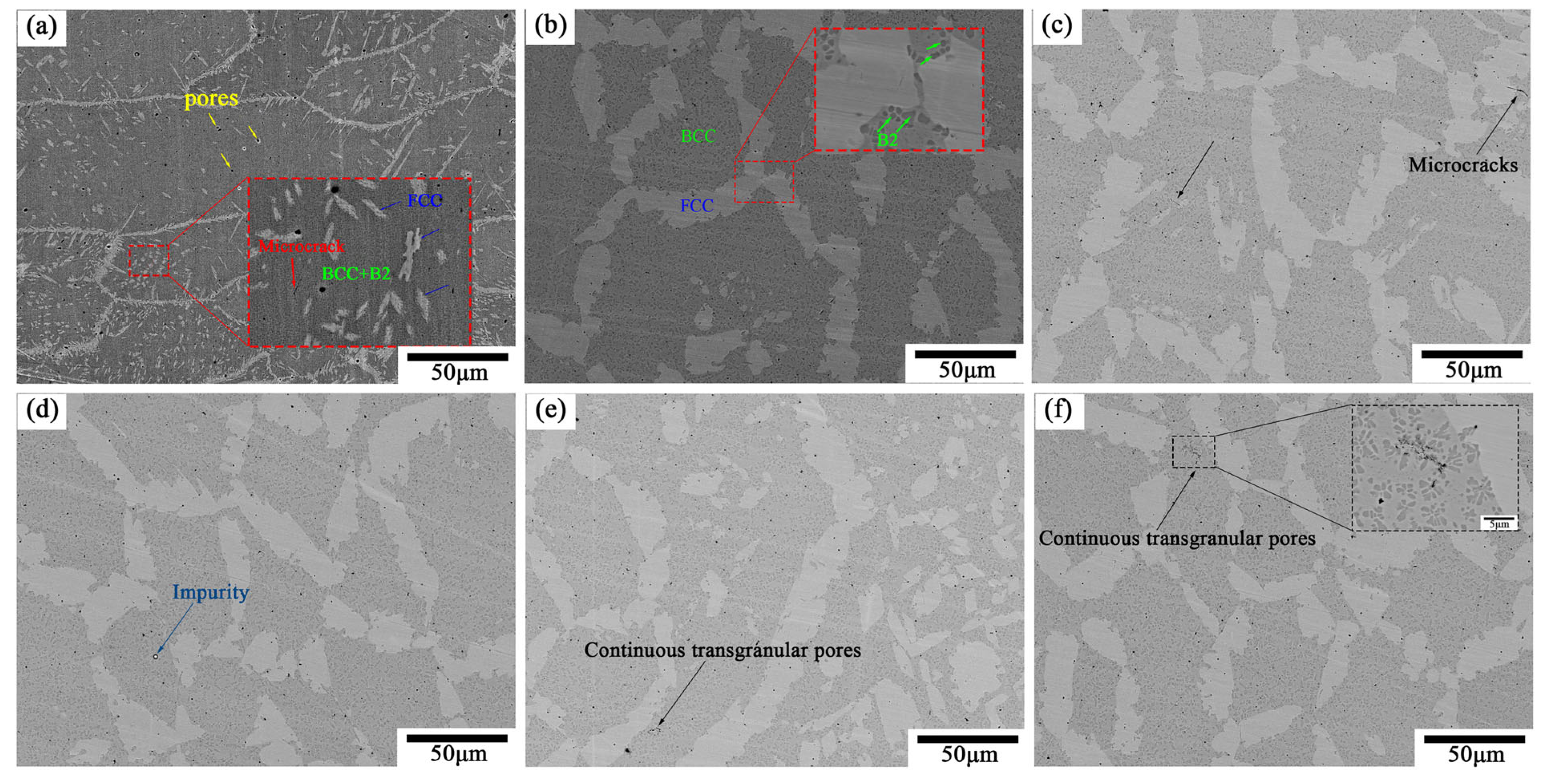
  • The specimens in both the as-printed and HIPed states exhibit FCC and BCC/B2 phase structures. Compared to the as-printed specimens, HIP promotes the formation of the BCC phase in HEAs and increases the proportion of the BCC/FCC phases. Additionally, HIP effectively closes the pores, increasing the material’s density to 98.2%.
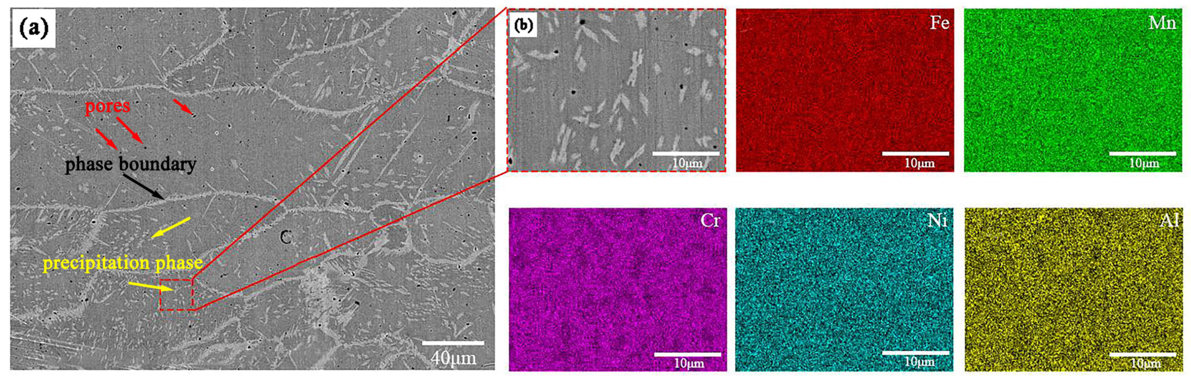
  • For as-printed specimens, bright, needle-like (lamellar) FCC phases are irregularly distributed near grain boundaries and within grains, and uniformly distributed pores of varying sizes exist at the phase boundaries and within the phases, along with a limited number of microcrack defects. The BCC phase is uniformly distributed, with tiny clumps of B2 phases present on the BCC phase substrate. The microstructure of the HIPed specimens clearly showed a redistribution of two phases: the FCC phase is irregularly distributed between the BCC phase in the form of strips, while a substantial B2 phase is present within the BCC phase, and there is a notable reduction in defects such as porosity and microcracks.
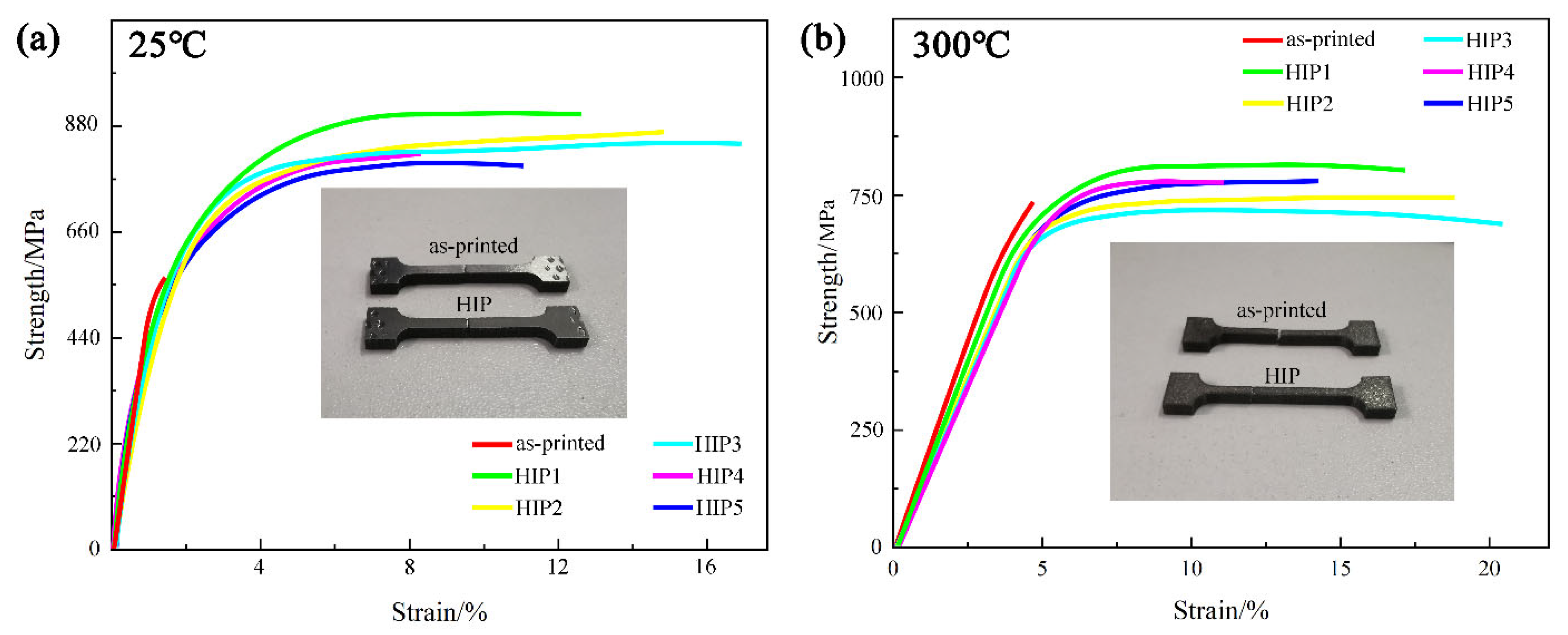
  • At room temperature, as-printed samples experienced premature fracture due to stress concentration caused by internal microcracks. In comparison to as-printed samples, the HIPed samples exhibited higher σUTS and εf, with σUTS reaching 903.9 MPa and εf reaching 17.4%. The tensile samples at 300 °C exhibit a similar trend, with the σUTS of HIPed samples reaching 800.7 MPa and the εf reaching 20.5%. An increase in HIP temperature results in a decrease in σUTS and an increase in εf, whereas an increase in pressure leads to a reduction in both σUTS and εf.
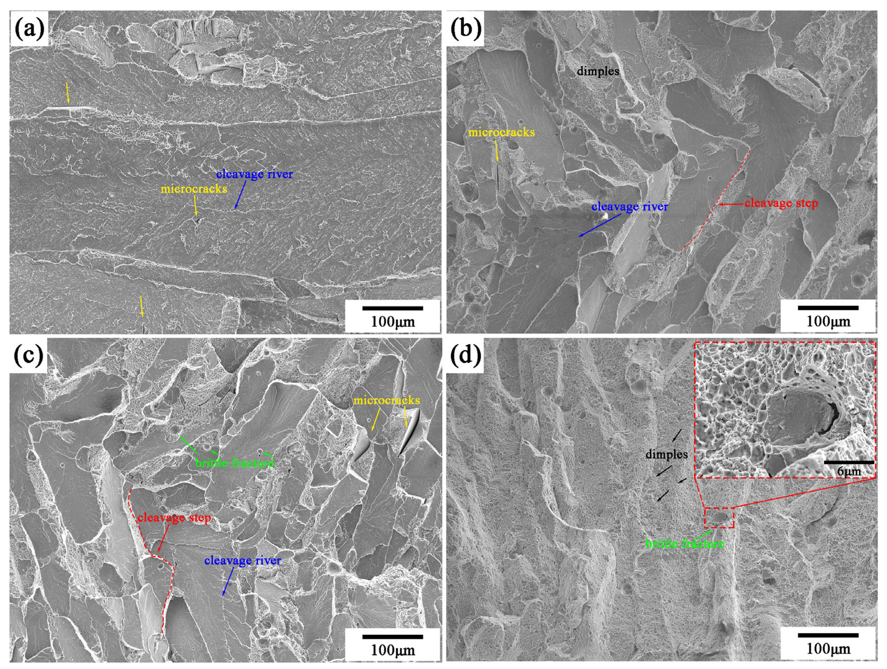
  • The fracture mechanism of as-printed HEA samples is characterized by microcrack-induced cleavage fracture, while the fracture mechanism of HIP-treated samples transitions to a coexistence of cleavage fracture and ductile fracture at room temperature. At 300 °C, the fracture mechanism of as-printed HEA samples also exhibits a coexistence of cleavage and ductile fractures, whereas the fracture mechanism of HIPed samples evolves to primarily ductile fracture, with a limited number of brittle fracture points.

Author Contributions

Conceptualization, G.W.; methodology, X.L.; validation, X.L.; resources, G.W.; data curation, X.L.; writing—original draft, X.L.; writing—review and editing, X.X. and R.Z.; supervision, X.X. and R.Z. All authors have read and agreed to the published version of the manuscript.

Funding

This article is funded by the project: Key Technology Development of Integrated Casting Magnesium Aluminum Alloy Structural Components—Research and Application of Key Technologies for Homogeneous and Heterogeneous Connections and Corrosion Protection of Magnesium Aluminum Alloy. Project Approval Number: 20220301025GX.

Data Availability Statement

The original contributions presented in the study are included in the article. Further inquiries can be directed to the corresponding author.

Conflicts of Interest

The authors declare no conflict of interest.

References

  1. Yeh, J.W.; Chen, S.-K.; Lin, S.-J.; Gan, J.-Y.; Chin, T.-S.; Shun, T.-T.; Tsau, C.-H.; Chang, S.-Y. Nanostructured high-entropy alloys with multiple principal elements: Novel alloy design concepts and outcomes. Adv. Eng. Mater. 2004, 6, 299–303. [Google Scholar] [CrossRef]
  2. Cantor, B.; Chang, I.T.H.; Knight, P.; Vincent, A.J.B. Microstructural development in equiatomic multicomponent alloys. Mater. Sci. Eng. A 2004, 375–377, 213–218. [Google Scholar] [CrossRef]
  3. Zhang, Y.; Zhou, Y.J.; Lin, J.P.; Chen, G.L.; Liaw, P.K. Solid-solution phase formation rules for multi-component alloys. Adv. Eng. Mater. 2008, 10, 534–538. [Google Scholar] [CrossRef]
  4. Tsai, M.; Yeh, J. High-entropy alloys: A critical review. Mater. Res. Lett. 2014, 2, 107–123. [Google Scholar] [CrossRef]
  5. Guo, S.; Liu, C.T. Phase stability in high entropy alloys: Formation of solid-solution phase or amorphous phase. Prog. Nat. Sci. 2011, 21, 433–446. [Google Scholar] [CrossRef]
  6. Joseph, J.; Jarvis, T.; Wu, X.; Stanford, N.; Hodgson, P.; Fabijanic, D.M. Comparative study of the microstructures and mechanical properties of direct laser fabricated and arc-melted AlCoCrFeNi high entropy alloys. Mater. Sci. Eng. A 2015, 633, 184–193. [Google Scholar] [CrossRef]
  7. Otto, F.; Yang, Y.; Bei, H.; George, E.P. Relative effects of enthalpy and entropy on the phase stability of equiatomic high-entropy alloys. Acta Mater. 2013, 61, 2628–2638. [Google Scholar] [CrossRef]
  8. Guo, L.; Gu, J.; Gong, X.; Li, K.; Ni, S.; Liu, Y.; Song, M. Short-range ordering induced serrated flow in a carbon contained FeCoCrNiMn high entropy alloy. Micron 2019, 126, 102739. [Google Scholar] [CrossRef] [PubMed]
  9. Brif, Y.; Thomas, M.; Todd, L. The use of high-entropy alloys in additive manufacturing. Scr. Mater. 2015, 99, 93–96. [Google Scholar] [CrossRef]
  10. Chou, H.-P.; Chang, Y.-S.; Chen, S.-K.; Yeh, J.-W. Microstructure, thermophysical and electrical properties in AlxCoCrFeNi (0 ≤ x ≤ 2) high-entropy alloys. Mater. Sci. Eng. B 2009, 163, 184–189. [Google Scholar] [CrossRef]
  11. Lin, C.; Tsai, H. Evolution of microstructure, hardness, and corrosion properties of high-entropy Al0.5CoCrFeNi alloy. Intermetallics 2011, 19, 288–294. [Google Scholar] [CrossRef]
  12. Li, R.; Niu, P.; Yuan, T.; Cao, P.; Chen, C.; Zhou, K. Selective laser melting of an equiatomic CoCrFeMnNi high-entropy alloy: Processability, non-equilibrium microstructure and mechanical property. J. Alloys Compd. 2018, 746, 125–134. [Google Scholar] [CrossRef]
  13. Zhang, M.; Ma, Y.; Dong, W.; Liu, Z.; Lu, Y.; Zhang, Y.; Li, R.; Wang, Y.; Yu, P.; Gao, Y.; et al. Phase evolution, microstructure, and mechanical behaviors of the CrFeNiAlxTiy medium-entropy alloys. Mater. Sci. Eng. A 2020, 771, 138566. [Google Scholar] [CrossRef]
  14. Wang, H.; Zhang, W.; Gao, P.; Xiang, Q.; Qu, Y.; Cheng, J.; Ren, Y.; Qiu, K. AlxFeCrNi medium entropy alloys with high damping capacity. J. Alloys Compd. 2021, 876, 159991. [Google Scholar] [CrossRef]
  15. Jiao, W.; Li, T.; Chang, X.; Lu, Y.; Yin, G.; Cao, Z.; Li, T. A novel Co-free Al0.75CrFeNi eutectic high entropy alloy with superior mechanical properties. J. Alloys Compd. 2022, 902, 163814. [Google Scholar] [CrossRef]
  16. Chen, X.; Qi, J.Q.; Sui, Y.W.; He, Y.Z.; Wei, F.X.; Meng, Q.K.; Sun, Z. Effects of aluminum on microstructure and compressive properties of Al-Cr-Fe-Ni eutectic multi-component alloys. Mater. Sci. Eng. A 2017, 681, 25–31. [Google Scholar] [CrossRef]
  17. Wang, M.; Wen, Z.; Liu, J.; Ma, B.; Wang, M.; Zou, Z.; Zhao, Y. Labyrinthine structure AlxCrFeNi (x ≥ 1) eutectic high entropy alloys with duplex reinforced phases. J. Alloys Compd. 2022, 918, 165441. [Google Scholar]
  18. Liu, M.; Zuo, L.; Li, X.; Li, R.; Zhang, T. Microstructure and Mechanical Properties of Al25−xCr25+0.5xFe25Ni25+0.5x (x = 19, 17, 15 at %) Multi-Component Alloys. Adv. Eng. Mater. 2018, 20, 1–7. [Google Scholar] [CrossRef]
  19. Tripathy, B.; Malladi, S.R.K.; Bhattacharjee, P.P. Development of ultrafine grained cobalt-free AlCrFe2Ni2 high entropy alloy with superior mechanical properties by thermo-mechanical processing. Mater. Sci. Eng. A 2022, 83, 142190. [Google Scholar] [CrossRef]
  20. Tripathy, B.; Saha, R.; Bhattacharjee, P.P. Microstructure and unusually strong recrystallization texture of the FCC phase of a cost-effective high-strength dual-phase AlCrFe2Ni2 high entropy alloy. Intermetallics 2022, 145, 107559. [Google Scholar] [CrossRef]
  21. Fan, J.; Fu, L.; Sun, Y.; Xu, F.; Ding, Y.; Wen, M.; Shan, A. Unveiling the precipitation behavior and mechanical properties of Co-free Ni47-xFe30Cr12Mn8AlxTi3 high-entropy alloys. J. Mater. Sci. Technol. 2022, 118, 25–34. [Google Scholar] [CrossRef]
  22. Song, F.-Y.; Zhang, J.; Guo, H.; Zhang, M.; Zhao, Y.; Sha, J.B. Research on application of hot isostatic pressing technology in the field of nickel-based cast superalloys. J. Mater. Eng. 2021, 49, 65–74. [Google Scholar] [CrossRef]
  23. Xuan, W.; Zhang, X.; Zhao, Y.; Li, J.; Wang, B.; Ren, X.; Ren, Z. Mechanism of improved intermediate temperature plasticity of nickel-base single crystal superalloy with hot isostatic pressing. J. Mater. Res. Technol. JmrT 2021, 14, 1609–1617. [Google Scholar] [CrossRef]
  24. Wang, X.; Zhu, L.; Yu, W.; Ding, X.; Nan, H. Research Progress of Powder Hot Isostatic Pressing for Intermetallic Titanium Aluminide. Rare Met. Mater. Eng. 2021, 50, 3797–3808. [Google Scholar]
  25. Jin, X.; Bi, J.; Zhang, L.; Zhou, Y.; Du, X.; Liang, Y.; Li, B. A new CrFeNi2Al eutectic high entropy alloy system withexcellent mechanical properties. J. Alloys Compd. 2019, 770, 655–661. [Google Scholar] [CrossRef]
  26. Cui, P.; Liu, Y.; Zhou, F.; Lai, Z.; Zhu, J. Enhancing high temperature mechanical properties via modulating B2 phase with Al contents in FeCrNiAlx (x = 0.63, 0.71, 0.77) high entropy alloys. J. Alloys Compd. 2022, 903, 163883. [Google Scholar] [CrossRef]
  27. Chen, R.; Qin, G.; Zheng, H.; Wang, L.; Su, Y.; Chiu, Y.L.; Ding, H.; Guo, J.; Fu, H. Composition design of high entropy alloys using the valence electron concentration to balance strength and ductility. Acta Mater. 2018, 144, 129–137. [Google Scholar] [CrossRef]
  28. Dong, Y.; Yao, Z.; Huang, X.; Du, F.; Li, C.; Chen, A.; Cheng, Y.; Zhang, Z. Microstructure and mechanical properties of AlCoxFeCrNi3-x eutectic high-entropy-alloy system. J. Alloys Compd. 2020, 823, 153886. [Google Scholar] [CrossRef]
  29. Zhao, Y.L.; Yang, T.; Tong, Y.; Wang, J.; Huan, J.H.; Jiao, Z.B.; Chen, D.; Yang, Y.; Hu, A.; Liu, C.T.; et al. Heterogeneous precipitation behavior andstacking-fault-mediated deformation in a CoCrNi-based medium-entropy alloy. Acta Mater. 2017, 138, 72–82. [Google Scholar] [CrossRef]
  30. Liu, N.; Ding, W.; Wang, X.J.; Zhang, J.; Zhou, P.J.; Chen, M. Phases, microstructures and properties ofmulti-component FeCoNi-based alloys. Mater. Sci. Technol. 2020, 36, 654–660. [Google Scholar] [CrossRef]
  31. Hemphill, M.A.; Yuan, T.; Wang, G.Y.; Yeh, J.W.; Tsai, C.W.; Chuang, A.; Liaw, P.K. Fatigue behavior of Al0.5CoCrCuFeNi high entropy alloys. Acta Mater. 2012, 16, 5723–5734. [Google Scholar] [CrossRef]
  32. Yang, T.F.; Xia, S.Q.; Wang, C.; Liu, S.; Zhang, Y.; Xue, J.; Yan, S.; Wang, Y. Effects of Al addition on microstructure and mechanical properties of AlxCoCrFeNi High-entropy alloy. Mater. Sci. Eng. A 2015, 648, 15–22. [Google Scholar] [CrossRef]
  33. Chao, Q.; Guo, T.; Jarvis, T.; Wu, X.; Hodgson, P.; Fabijanic, D. Direct laser deposition cladding of AlxCoCrFeNi high entropy alloys on a high-temperature stainless steel. Surf. Coat. Technol. 2017, 332, 440–451. [Google Scholar] [CrossRef]
  34. Asadikiya, M.; Zhang, Y.; Wang, L.; Apelian, D.; Zhong, Y. Design of ternary high-entropy aluminum alloys (HEAls). J. Alloys Compd. 2022, 891, 161836. [Google Scholar] [CrossRef]
  35. Gao, X.Z.; Lu, Y.; Zhang, B.; Liang, N.; Wu, G.; Sha, G.; Liu, J.; Zhao, Y. Microstructural origins of high strength and high ductility in an AlCoCrFeNi2.1 eutectic high-entropy alloy. Acta Mater. 2017, 141, 59–66. [Google Scholar] [CrossRef]
  36. Ye, Y.F.; Wang, Q.; Lu, J.; Liu, C.T.; Yang, Y. High-entropy alloy: Challenges and prospects. Mater. Today 2016, 19, 349–362. [Google Scholar] [CrossRef]
  37. Guo, S.; Ng, C.; Lu, J.; Liu, T. Effect of valence electron concentration on stability of fcc or bcc phase in high entropy alloys. J. Appl. Phys. 2011, 109, 103505. [Google Scholar] [CrossRef]
  38. Laughlin, D.E.; Soffa, W.A. Metals Handbook, 9th ed.; ASM Press: Washington, DC, USA, 1985; Volume 9. [Google Scholar]
  39. Para, S. Metallography and microstructure. In ASM Handbook; ASM Press: Washington, DC, USA, 2004; Volume 9. [Google Scholar]
  40. Wang, W.R.; Wang, W.L.; Yeh, J.W. Phases, microstructure and mechanical properties of AlxCoCrFeNi high-entropy alloys at elevated temperatures. J. Alloys Compd. 2014, 589, 143–152. [Google Scholar] [CrossRef]
  41. Zhang, Y.; Zuo, T.T.; Tang, Z.; Gao, M.C.; Dahmen, K.A.; Liaw, P.K.; Lu, Z.P. Microstructures and properties of high-entropy alloys. Prog. Mater. Sci. 2014, 61, 1–93. [Google Scholar] [CrossRef]
  42. Jiao, Z.B.; Luan, J.H.; Miller, M.K.; Yu, C.Y.; Liu, C.T. Effects of Mn partitioning on nanoscale precipitation and mechanical properties of ferritic steels strengthened by NiAl nanoparticles. Acta Mater. 2015, 84, 283–291. [Google Scholar] [CrossRef]
  43. Yao, M.J.; Pradeep, K.G.; Tasan, C.C.; Raabe, D. A novel, single phase, non-equiatomic FeMnNiCoCr high-entropy alloy with exceptional phase stability and tensile ductility. Scr. Mater. 2014, 72–73, 5–8. [Google Scholar] [CrossRef]
  44. Bracq, G.; Laurent-Brocq, M.; Perriere, L.; Pires, R.; Joubert, J.-M.; Guillot, I. The fcc solid solution stability in the Co-Cr-Fe-Mn-Ni multi-component system. Acta Mater. 2017, 128, 327–336. [Google Scholar] [CrossRef]
  45. Christofidou, K.A.; Pickering, E.J.; Orsatti, P.; Mignanelli, P.M.; Slater, T.J.A.; Stone, H.J.; Jones, N.G. On the influence of Mn on the phase stability of the CrMnx FeCoNi high entropy alloys. Intermetallics 2018, 92, 84–92. [Google Scholar] [CrossRef]
  46. Darwich, A.; Attieh, A.; Khalil, A.; Szavai, S.; Nazha, H. Biomechanical assessment of orbital fractures using patient-specific models and clinical matching. J. Stomatol. Oral Maxillofac. Surg. 2021, 122, E51–E57. [Google Scholar] [CrossRef]
  47. Kono, S.; Vaidya, A.; Takahashi, Y. Mechanisms of Development of Orbital Fractures: A Review. Ophthalmic Plast. Reconstr. Surg. 2023, 39, 542–547. [Google Scholar] [CrossRef]
  48. Li, B.; Yu, S.; Yang, L.; Zhu, W.; Xue, Y.; Feng, D.; Wang, C.; Chen, Y. Multiscale fracture characteristics and failure mechanism quantification method of cracked rock under true triaxial compression. Eng. Fract. Mech. 2022, 262, 108257. [Google Scholar] [CrossRef]
  49. Zheng, S.; Shen, J.; Lu, X.; Xie, H.; Wang, W.; Yue, X. Microstructure inducement of different tensile fracture mechanisms at 800 °C of directional solidified Ti-45Al-5Nb alloys produced by electromagnetic confinement. J. Alloys Compd. 2022, 912, 165200. [Google Scholar] [CrossRef]
  50. Yang, J.; Wang, K.; Wu, J.; Zhang, Q.; Zhao, G.; Hu, P. Effect of misorientation evolution on the fracture mechanism. Mater. Lett. 2024, 357, 135742. [Google Scholar] [CrossRef]
  51. Yang, X.; Liang, Z.; Wang, L.W.; Zhang, H.; Wang, D.L. Interface structure and tensile behavior of high entropy alloy particles reinforced Al matrix composites by spark plasma sintering. Mater. Sci. Eng. A-Struct. Mater. Prop. Microstruct. Process. 2022, 860, 144273. [Google Scholar] [CrossRef]
  52. Xi, S.; Chen, H.; Zhou, J.; Zheng, L.; Wang, W.; Nie, H.; Zheng, Q.; Liu, B. A novel eutectic high-entropy matrix composites were prepared by selective laser melting: Microstructure evolution, strengthening and fracture mechanism. J. Manuf. Process. 2024, 120, 1035–1048. [Google Scholar] [CrossRef]
Figure 1. High-entropy alloy powder: (a) microstructural morphology; (b) enlarged view; (c) particle size distribution of the powder; (d) XRD pattern.
Metals 14 01452 g001
Figure 2. Schematic of the LMD Printing Process: (a) CNC machine; (b) powder feeder; (c) laser head; (d) LMD print; (e) as-printed specimen.
Metals 14 01452 g002
Figure 3. (a) XRD patterns; (b) enlarged patterns.
Metals 14 01452 g003
Figure 4. Density and the metallograph of cross-sections.
Metals 14 01452 g004
Figure 5. SEM of microstructures: (a) as-printed sample; (b) HIP2 sample; (cf) HIP1, HIP3, HIP4, and HIP5.
Metals 14 01452 g005
Figure 6. Element distribution maps of as-printed sample analyzed by EDS. (a) BSE Image; (b) Enlarged Image.
Metals 14 01452 g006
Figure 7. Element distribution maps of HIP2 sample analyzed by EDS. (a) BSE Image; (b) Enlarged Image.
Metals 14 01452 g007
Figure 8. Engineering stress–strain curves (a) 25 °C; (b) 300 °C.
Metals 14 01452 g008
Figure 9. Tensile fracture morphology: (a) as-printed sample at 25 °C; (b) HIPed sample at 25 °C; (c) as-printed sample at 300 °C; (d) HIPed sample at 300 °C.
Metals 14 01452 g009
Table 1. HIP Process Parameters.
SampleTemperature/°CPress/MpaTime/h
HIP111001502
HIP21150
HIP31200
HIP41150120
HIP5180
Table 2. Element point scanning by EDS.
RegionComposition/wt%
FeCrMnNiAl
Site136.7814.5822.7817.228.65
Site229.6317.4918.7717.8816.23
Site344.6725.4620.514.335.03
Table 3. Tensile properties of alloys.
SamplesTensile Properties (25 °C/300 °C)
σy/MPaσUTS/MPaεf/%
as-printed461.2/606.4556.6/744.81.8/5.1
HIP1440.5/587.6881.5/800.712.9/16.8
HIP2445.6/601.3903.9/713.514.7/18.1
HIP3441.2/588.6899.4/706.217.4/20.5
HIP4440.6/600.2802.3/696.78.8/11.6
HIP5435.1/595.5789.2/700.811.5/14.9
Disclaimer/Publisher’s Note: The statements, opinions and data contained in all publications are solely those of the individual author(s) and contributor(s) and not of MDPI and/or the editor(s). MDPI and/or the editor(s) disclaim responsibility for any injury to people or property resulting from any ideas, methods, instructions or products referred to in the content.

