Article

Analysis of the Structure and Properties of As-Built and Heat-Treated Wire-Feed Electron Beam Additively Manufactured (WEBAM) Ti–4Al–3V Spherical Pressure Vessel

1
Institute of Strength Physics and Materials Science of the Siberian Branch of the Russian Academy of Sciences, pr. Akademicheskii, 2/4, Tomsk 634055, Russia
2
Center for AeroSpace Materials & Technologies, Advanced School of Engineering, Moscow Aviation Institute, Volokolamskoe Shosse, 4, Moscow 125993, Russia
3
HSM Laboratory, Skolkovo Institute of Science and Technology, Moscow 121205, Russia
*
Author to whom correspondence should be addressed.
Metals 2024, 14(12), 1379; https://doi.org/10.3390/met14121379
Submission received: 23 October 2024 / Revised: 23 November 2024 / Accepted: 27 November 2024 / Published: 2 December 2024

Abstract

:
In the present work, a high-pressure spherical vessel was fabricated from Ti–4Al–3V titanium alloy using wire-feed electron beam additive manufacturing and characterized for tightness at high pressure. Studies have been carried out to characterize the microstructures and properties of the vessel’s material in four states: as-built (BM), annealed at 940 °C with cooling in air (HT1 treatment), quenched in water from 940 °C (HT2 treatment), and quenched with subsequent annealing at 540 °C (HT3 treatment). The microstructure of the as-built (BM) samples was composed of grain boundary α-Ti and α/β lath colonies located within the columnar primary β-Ti grain boundaries. The ultimate tensile strength of the as-built material was in the range of 582 to 632 MPa, i.e., significantly lower than that of the source Ti–4Al–3V alloy wire. The subtransus HT1 heat treatment allowed β→α″ transformation, while both HT2 and HT3 resulted in improved tensile strength due to the transformation of β-Ti into α/α′-Ti and the decomposition of α′ into α/β structures, respectively.

1. Introduction

Additive technologies, also known as 3D printing, have become an integral part of the arsenal of production techniques in a number of industries, including rocket and space, aviation and transportation, and energy [1,2,3]. The specific type of metal additive manufacturing employed is contingent upon the intended use, with the size and complexity of the product in question being the determining factors. For instance, in the production of small-sized products comprising numerous small parts, the preferred route is powder addition techniques, such as selective laser melting, directed energy deposition (blown powder), and electron beam melting [4,5]. However, direct metal deposition techniques, including wire and arc additive manufacturing and wire-feed electron beam additive manufacturing (also known as electron beam freeform fabrication), are frequently employed to produce large-scale components [6,7].
Being used on titanium alloys such as Ti–6Al–4V, these techniques offer high production speeds and facilitate the creation of near-net-shaped products. However, all of them are based on the fusion of powder or wire for layer-by-layer deposition and, therefore, result in forming an as-cast structure of the solidified metal. For Ti–6Al–4V, it means that high-aspect ratio columnar β-grains grow, and after the β→α transus, there are formed coarse α/β laths, which reduce the metal strength and add ductility. One of the methods for the elimination of these columnar grains is related to increasing the cooling rate, which, however, unavoidably provokes the formation of detrimental α′-Ti martensite. The cooling rate is higher with the laser powder-bed and wire arc AM methods compared to that of WEBAM, and therefore many results were reported on obtaining high-strength Ti–6Al–4V samples by means of these additive manufacturing methods. However, the WEBAM Ti–6A–-4V sample possesses low strength and high plasticity. Improvements in strength may be achieved by applying heat treatment.
The majority of studies examining the AM methods concentrate on the structure and characteristics of the so-called witness samples, which are defined as samples of a relatively simple shape, typically in the form of vertical walls [8,9,10,11]. Concurrently, the printing processes of complex-shape samples, particularly those of considerable size, diverge in terms of the thermal history of the sample due to the utilization of a sophisticated trajectory of product construction [12]. For instance, as becomes apparent [12], when printing bodies of rotation, the axis of vertical grain growth is deflected in the direction of heat dissipation, which has the potential to influence the tensile force behavior of the material. This characteristic of grain growth can be attributed to the waveform of the crystallization front, as elucidated [13].
In light of the above, the objective of this study was to examine the structure and mechanical properties of a large-scale sample of complex shape (high-pressure spherical vessel) produced by wire-feed electron beam additive manufacturing.

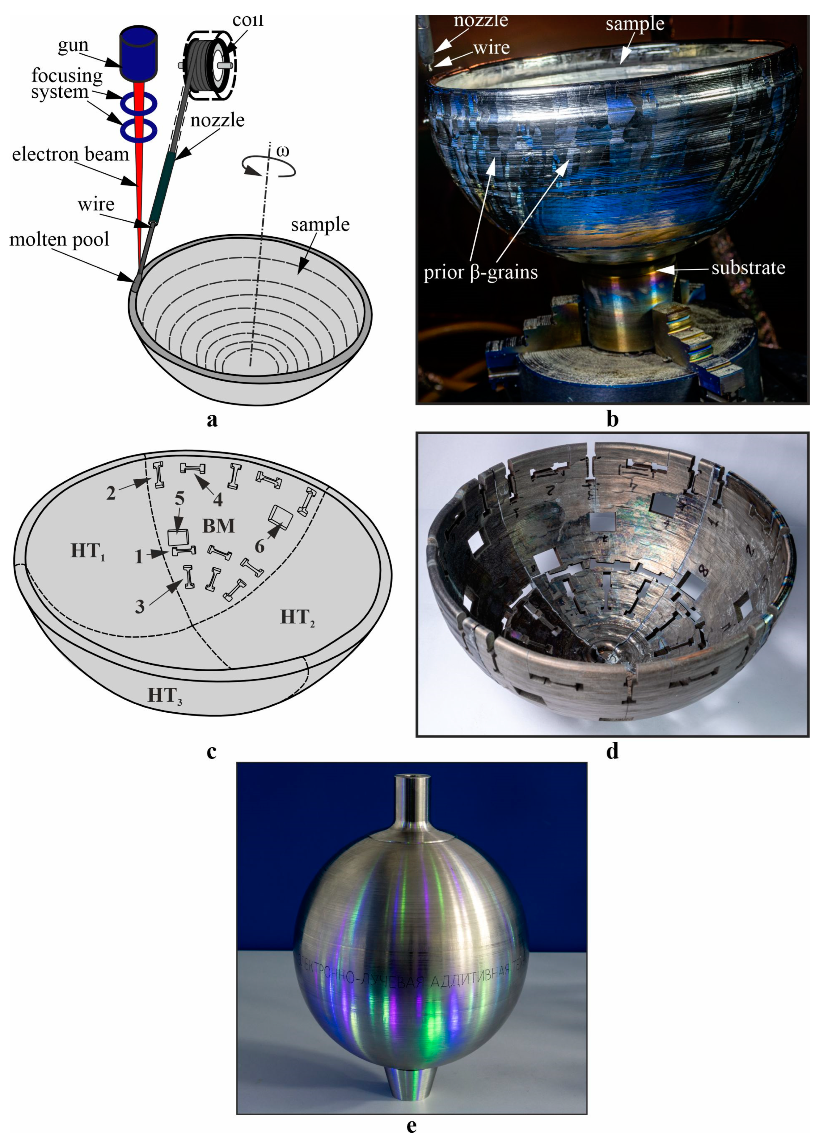
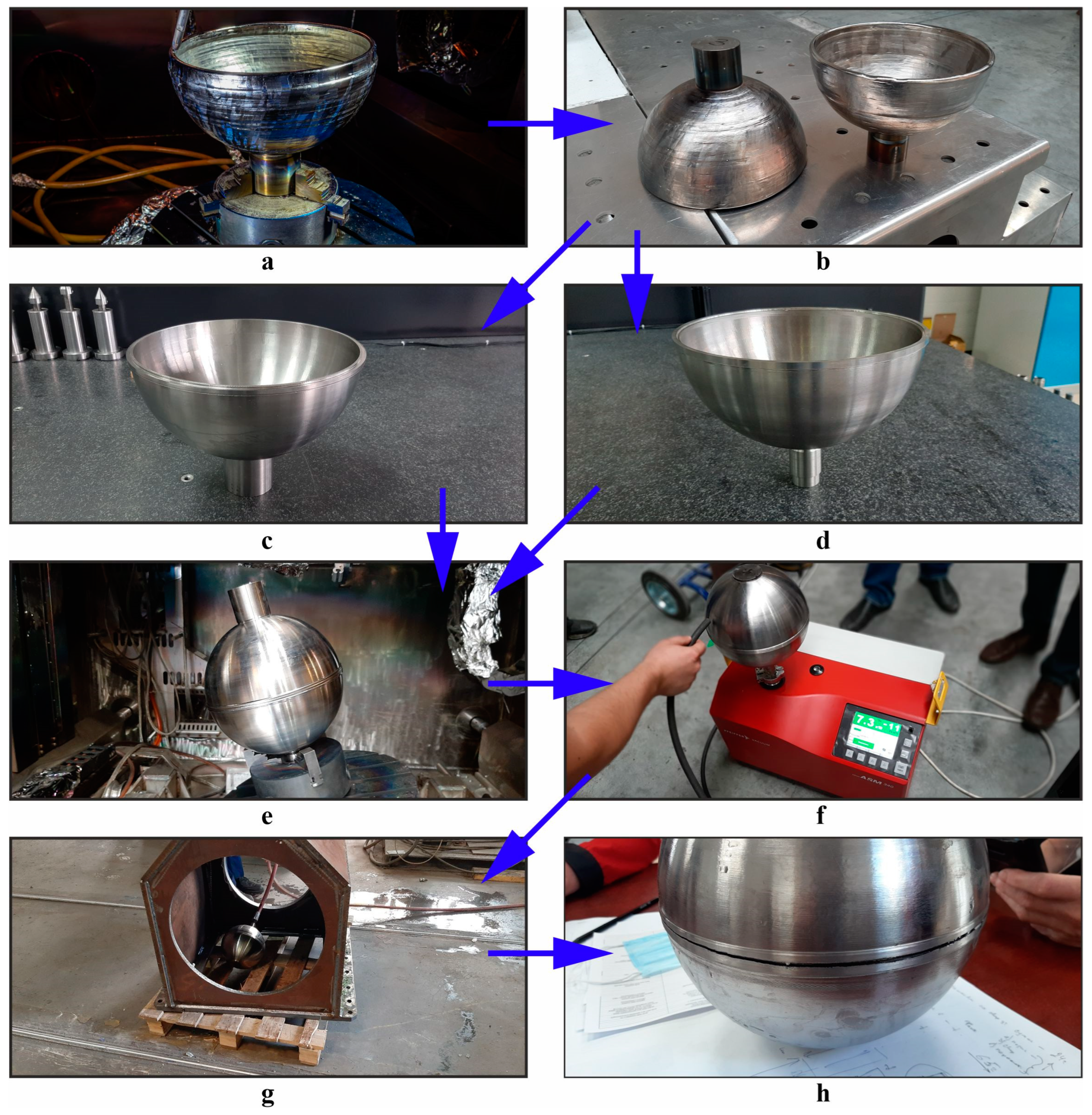
2. Materials and Methods

To carry out the research, a large-sized hemisphere intended for fabricating a high-pressure vessel of 5 dm3 capacity (Figure 1a) was obtained using a wire electron beam additive manufacturing (WEBAM) machine with a vacuum 8.0 m3 chamber at residual pressure not higher than 10−3 Pa (Institute of Strength Physics and Materials Science SB RAS, Tomsk, Russia). Ti–4Al–3V welding wire with a diameter of 2.0 mm is a commercially available, inexpensive product intended for welding Ti–6Al–4V workpieces, and the decision at this stage of the study was to use it as a feed wire for WEBAM fabrication of the vessel. The spherical vessel was fabricated in three main steps, as illustrated in Figure 2a–e.
In the first step, the simplest way was to use WEBAM for building two hemispherical workpieces (Figure 2a,b). The following WEBAM parameters were used: accelerating voltage of 30 kV, electron beam current of 45 mA, and linear printing speed of 440 mm/min. The next step was subtractive machining and polishing the hemispheres (Figure 2c,d) in order to improve the quality of both internal and external surfaces.
The final step was electron beam welding the hemispheres together to obtain a sphere (Figure 2e). The hemisphere edges were prepared to provide interlocking between the hemispheres, which were then joined using single-pass welding. The total number of WEBAM-built hemispheres was four, with two of them used for fabricating the spherical vessel and the other two cut into samples for investigation. The total time consumed for fabricating the spherical vessel was three working shifts, which was about 10 times shorter than the time taken using traditional all-subtractive manufacturing.
The sample cut-off scheme and the spherical vessel appearance are represented in Figure 1c,d and Figure 1e, respectively. The weld was tested for leakage using a leakage tester, Pfeiffer Vacuum ASM 34, at hydraulic pressures up to 400 atmospheres.
The resulting workpiece was cut into quarters using an electrical discharge cutting machine, DK7750 (Suzhou Simos CNC Technology Co., Ltd., Suzhou, China). One quarter part was examined in the original state (as-built), while the remaining three were subjected to three different heat treatments similar to those reported elsewhere [14].
One part of the as-built BM samples was annealed at the subtransus temperature of 940 °C for 1 h with cooling in air to the room temperature (HT1 treatment); another part was quenched in water (HT2 treatment) from 940 °C for 1 h; and the third part was quenched from 940 °C and then annealed at 540 °C for 1 h, followed by cooling in air (HT3 treatment). The samples were cut from from the heat-treated hemispheres as shown in Figure 1b. Structural studies were carried out using an Altami MET 1C optical microscope (Altami Ltd., Saint Petersburg, Russia) and an Olympus LEXT OLS4100 confocal laser scanning microscope (Olympus Corporation, Tokyo, Japan). Static tensile tests were performed using the UTS 110M-100 (Testsystems, Ivanovo, Russia) mechanical testing machine operated at a loading speed of 1 mm/min. Specimen gauge dimensions were 12 × 2.7 × 2.5 mm3.
The structural and phase state of the materials was studied using an X-ray diffractometer DRON-3 operated at 40 kV and 22 mA with CoKα radiation, Bragg–Brentano focusing geometry, a 0.05° sampling interval, 30 s counting time, and within the 2θ scan range of 35–100° (Bourevestnik, JSC, Saint Petersburg, Russia). The identification of XRD peaks and data processing were performed using Crystal Impact’s software “Match!” (version 3.9, Crystal Impact, Bonn, Germany).
The grain orientation functions and EDS spectra were obtained using the EBSD add-on Oxford Instruments Nordlys and Oxford Instruments Ultim Max 40 (Oxford Instruments, High Wycombe, UK) add-ons to an SEM instrument Tescan MIRA 3 LMU (TESCAN ORSAY HOLDING, Brno, Czech Republic). The EBSD and EDS examinations were carried out at an accelerating voltage of 20 kV with the electron beam currents of 20 nA and 3 nA, respectively.
Samples with dimensions of 4 × 2 × 1 mm3 were EDM cut from the hemispheres as illustrated in Figure 1c, pos.5, and then ∅3 mm disks were drilled out using a Dimpling Grinder Model 200 (Fischione Instruments, Export, PA, USA) followed by dimpling at the center down to 10–20 μm. The next step was argon ion beam milling at 7 kV for 9 h in a TEM Mill Model 1051 dual-beam ion polishing system (Fischione Instruments, Export, PA, USA) until perforating a hole with surrounding 100–200 nm thick edges.
A TEM instrument JEOL-2100 (JEOL Ltd., Tokyo, Japan) with a 200 kV accelerating voltage and EDS add-on (Oxford Instruments) was used for detecting phases and examining the microstructures.

3. Results

The helium leakage test results demonstrated complete tightness of the WEBAM-produced spherical vessel (Figure 2f). The next step was leakage testing using the hydraulic pressure method (Figure 2g,h). Since the working pressure of the spherical vessel was 200 atm, proof testing was carried out at pressure levels exceeding 400 atm. As a result of this testing, it was found that the WEBAM-produced sphere vessel fractured at pressures in the range of 410–420 atm. Predictably, the fracture occurred and propagated along the girth weld (Figure 2h), which served as the weak part of the vessel. These pressure testing results led to the conclusion that the WEBAM spherical vessel, fabricated from Ti–4Al–3V welding wire, possessed suitable strength.

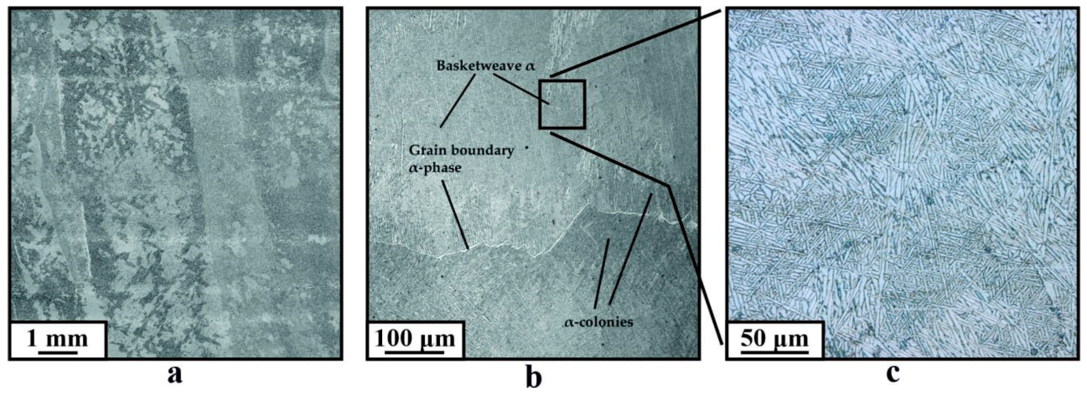
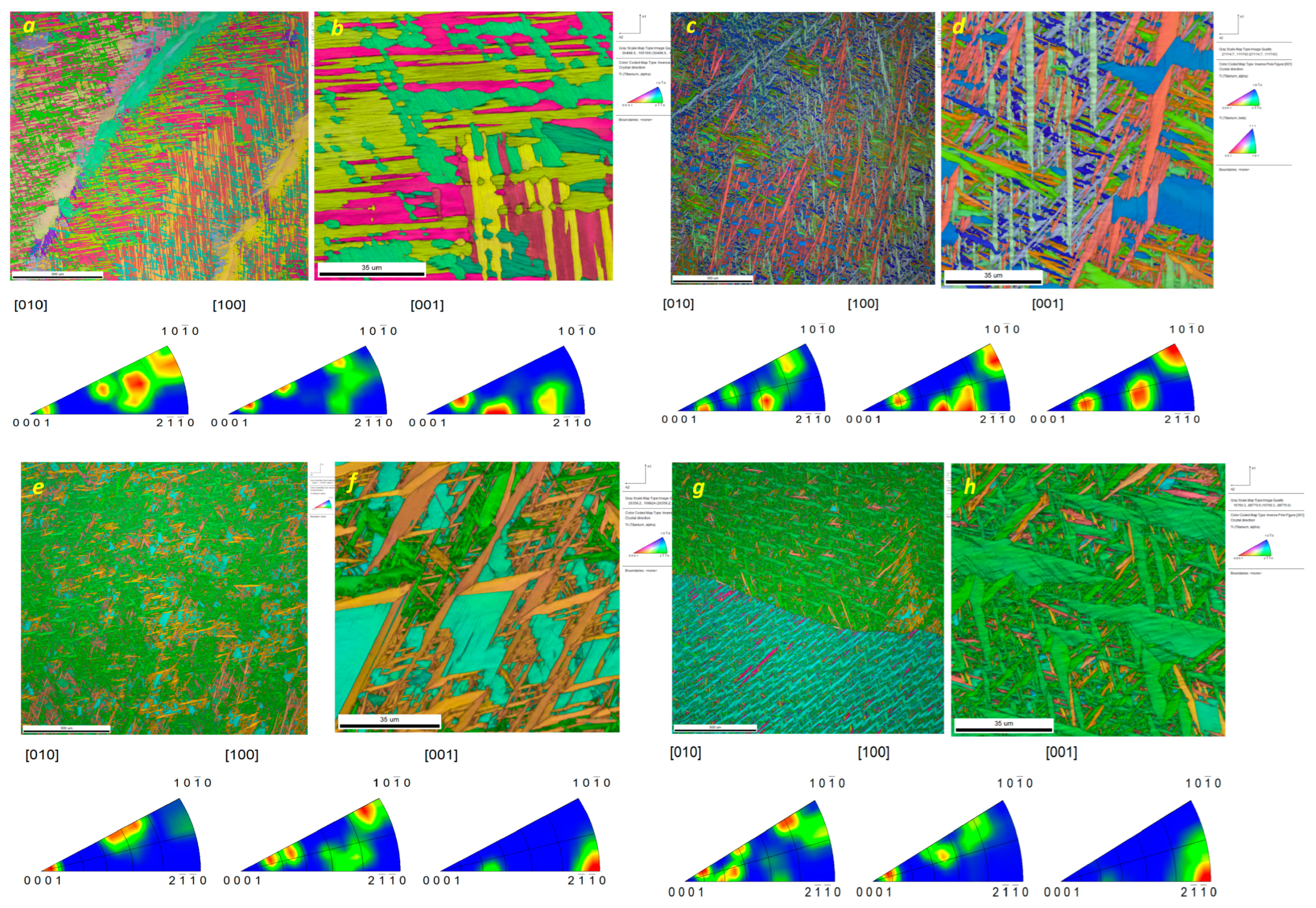
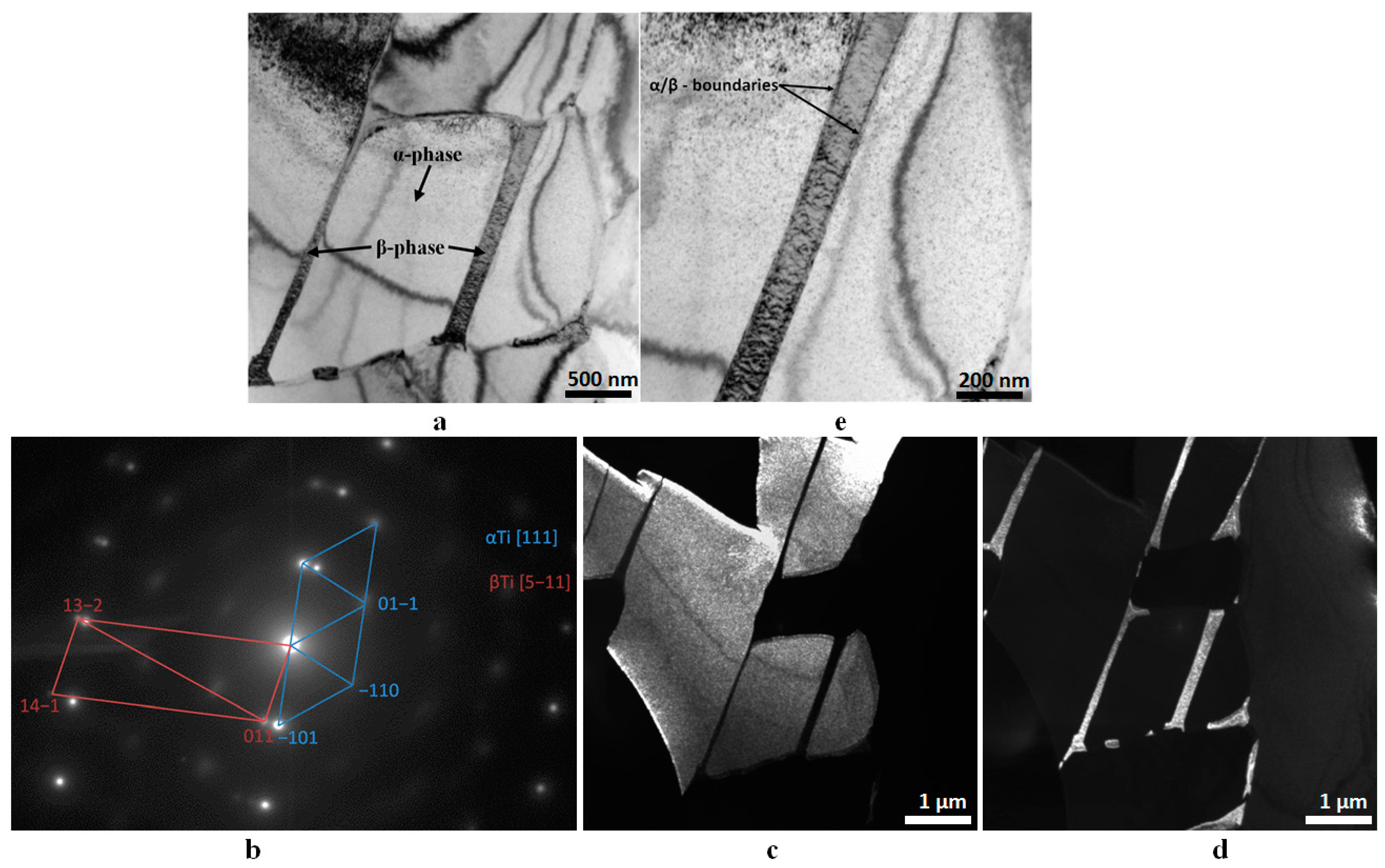
3.1. As-Built BM Material

Examination of microstructures formed in the as-built metal samples cut from the high-pressure vessel part BM (Figure 1) allowed observation of microstructures typical of the Ti–6Al–4V obtained via additive manufacturing, characterized by the presence of grain boundaries inherited from large columnar β-Ti primary grains, with their long axes oriented along the direction of heat removal (Figure 3a). It is also worth noting that the samples did not contain any defects caused by the additive process, such as, for example, spherical pores or cracks. The long axes of the columnar grains deviated by 20–30 degrees from the vertical symmetry axis due to the scanning strategy of the electron beam, as the vessel hemisphere was built as a body of rotation. Inside the β-Ti primary grain boundaries, there were typical as-cast microstructures composed of allotriomorphic (grain boundary) αGB-Ti, coarse α/β lath colonies with a mean size in the range of 100–150 μm, and refined “basket-weave” α/β colonies with sizes in the range of 50–90 μm, which grew inside the former β-grain (Figure 3b,c) [15].
With the exception of the deviation in the growth axis of the columnar grains, no visible differences were detected compared to standard research samples obtained by WEBAM in the form of vertical walls. The results of the mechanical tests showed that the as-built material of the WEBAM high-pressure vessel had a significantly lower ultimate tensile strength (UTS) compared to the reference values for this alloy. In the bottom part of the hemisphere, near the substrate, the ultimate strength values of the material measured along the building direction (sample 3) and along the layer deposition direction (sample 1) were 590 ± 22 MPa and 582 ± 22 MPa, respectively. In this case, the strain-to-fracture (STF) was at the level of about 7–10%. Figure 4 shows the stress–strain curves for the specimens that exhibiting both the highest and lowest tensile strength values to illustrate the scatter of the data obtained when tested in different directions. In the upper part of the hemisphere, the as-built material demonstrates higher UTS values: 632 ± 14 MPa and 623 ± 15 Mpa, as measured along the building (sample 2) and layer deposition (sample 4) directions, respectively. The STF values lie within the 10–12% range.
In comparison with the Ti–6Al–4V ELI alloy, the obtained values are more than 30% lower compared to those reported [15]. However, they may be considered acceptable when compared to the UTS of the Ti–4Al–3V wire, which is 712 ± 18 MPa. The differences in strength levels may be related to the lower content of both aluminum and vanadium in the welding wire. Overall, it is concluded that the strength of the WEBAM spherical vessel is high enough to comply with the best industry practices.
The results of mechanical testing on the as-built samples revealed only weak strength anisotropy of 7% with respect to tensile axis directions. An even lower 1.5% anisotropy was measured on samples cut from different heights along the building direction.

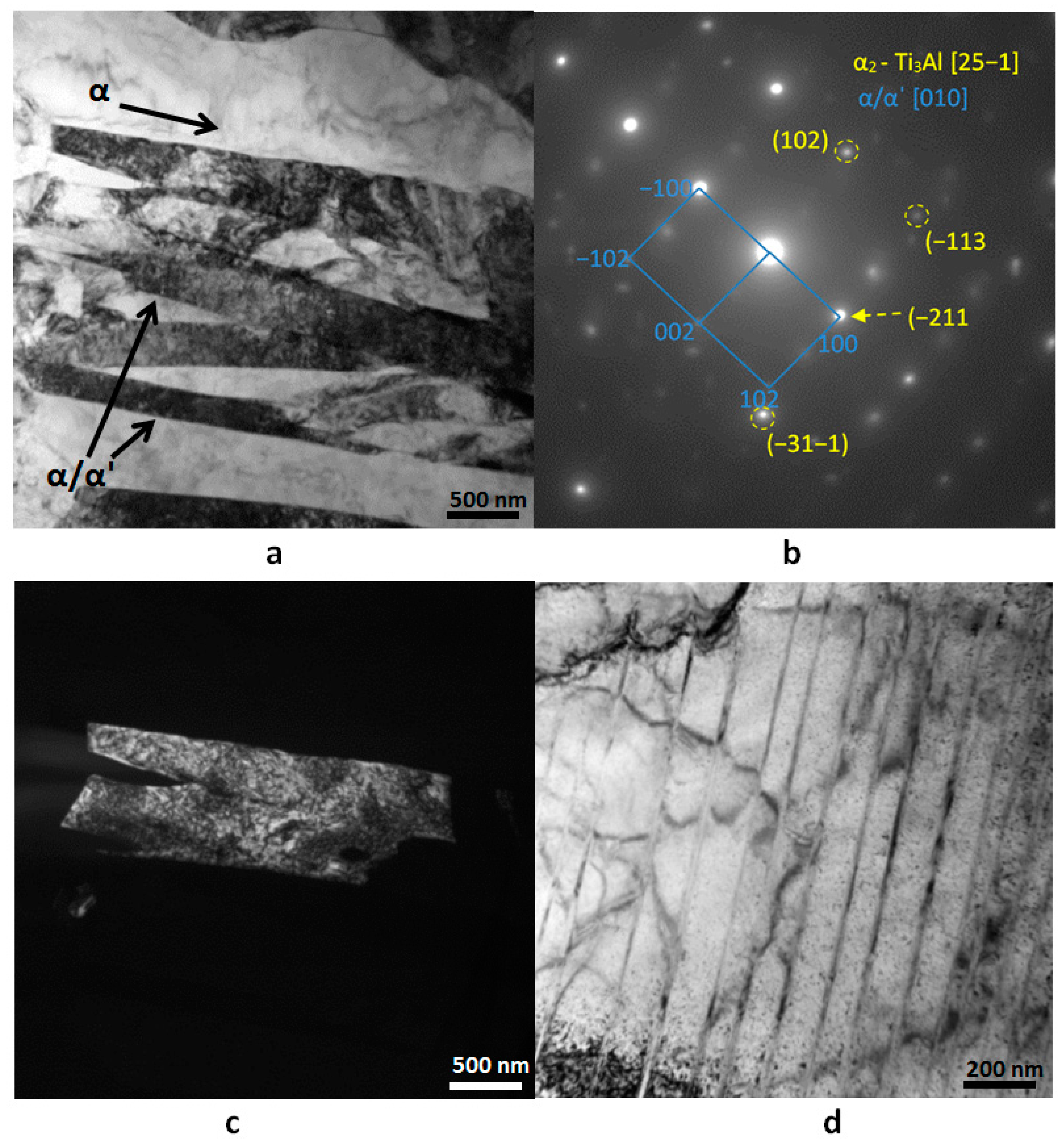
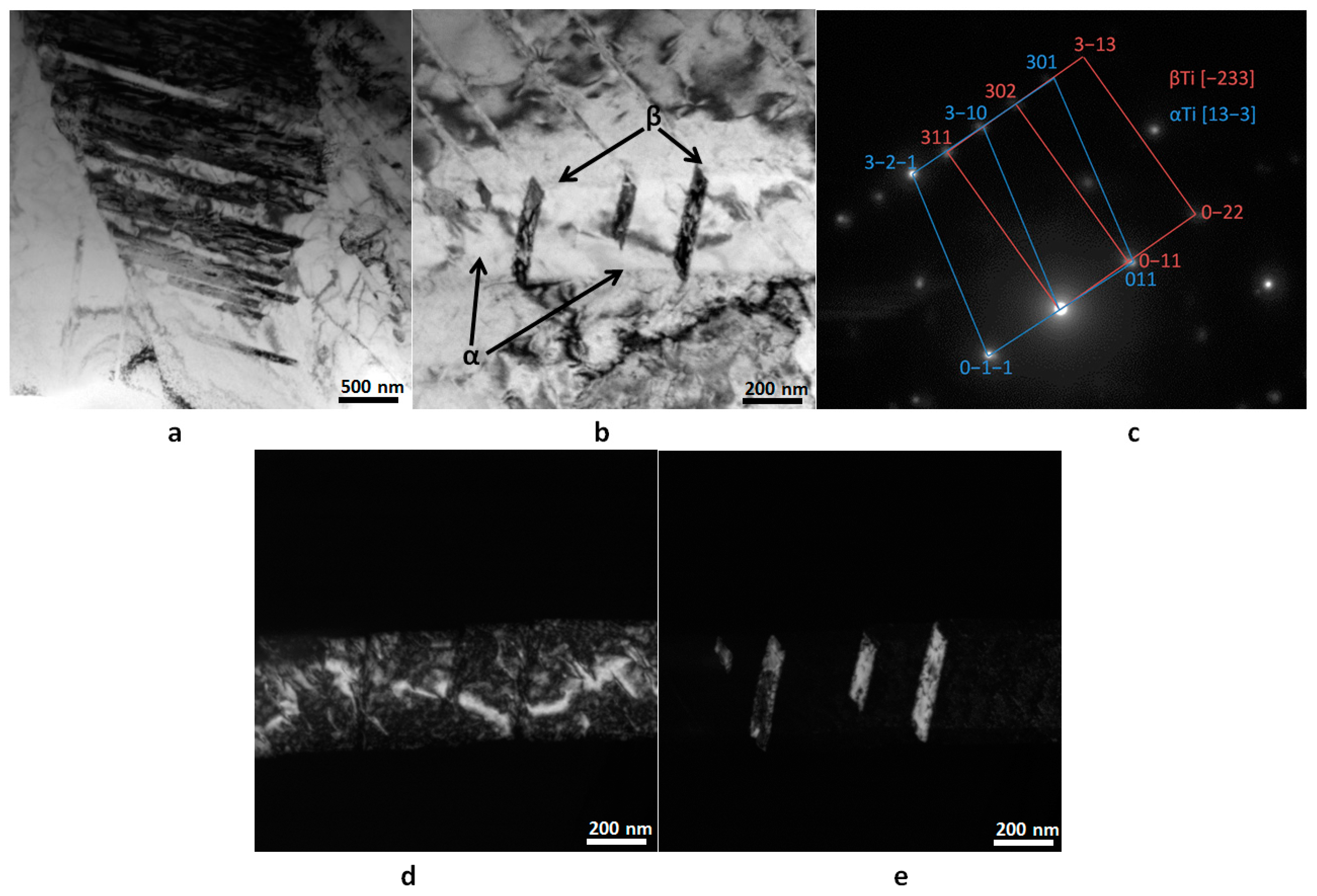
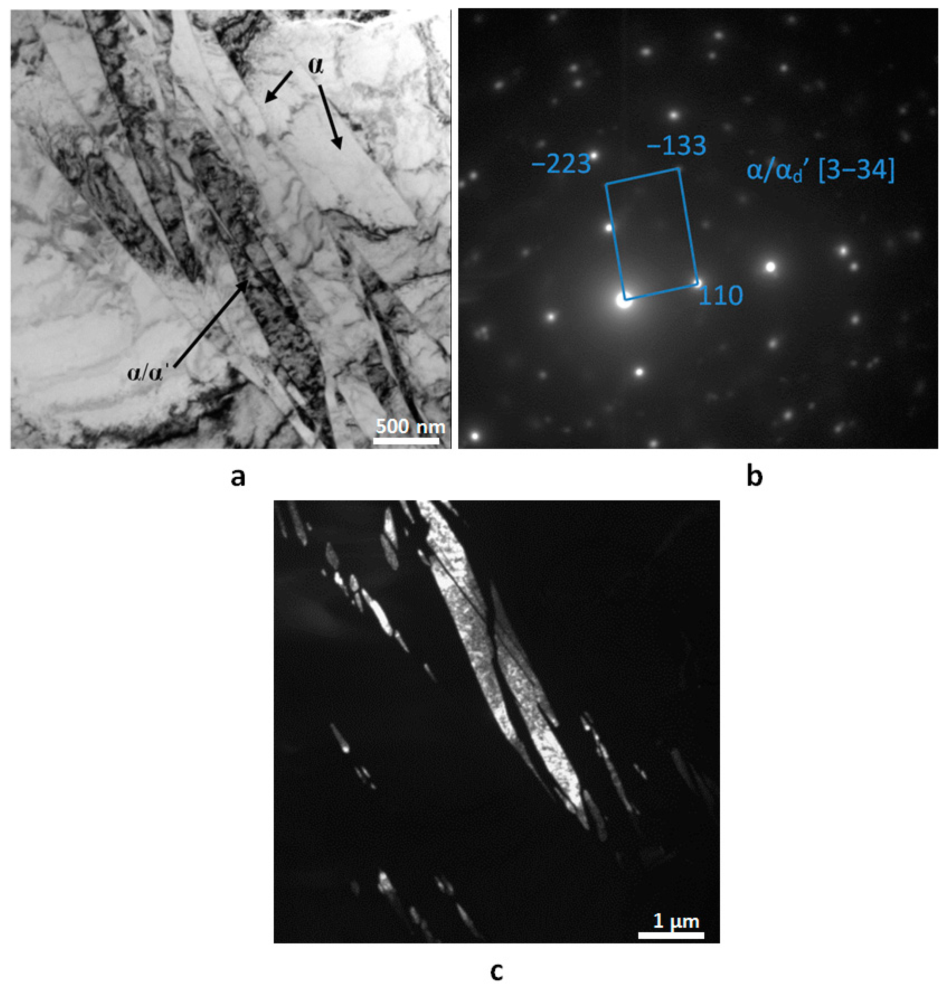
3.2. Heat-Treated Material

The structure of the material after HT1 annealing is practically no different from that of the as-built metal and is also represented by αGB, α/β colonies, and basket-weaved α-laths inside the former β-Ti grains (Figure 5).
Quenching in water (HT2) from the subtransus temperature significantly modified the microstructure of the as-built alloy, which is now represented by large α-laths that form a zigzag pattern (Figure 5b), with the space between them filled with smaller α-Ti laths. A similar pattern was observed after quenching followed by annealing at 540 °C (HT3), as is clearly visible in Figure 5c.
EBSD grain orientation maps show preferential α-Ti grain orientations for all samples (Figure 6). The as-built material can be characterized by the maximum content of grain boundaries with misorientation angles of 60° (Type 2), 60.8° (Type 3), and 63.3° (Type 4) [16]. Annealing at the subtransus temperature (HT1), quenching (HT2), and quenching with annealing at 540 °C (HT3) reduced the fraction of these boundaries from ~47% to ~30%, with a simultaneous increase in the fractions of both Type 6 (10.53°) and Type 5 (90°) grain boundaries (Figure 7).
The results of mechanical tests of these samples showed that HT1 annealing did not lead to a significant improvement in the properties of the material (Figure 8). The HT1 samples demonstrated a tensile strength of 600 ± 26 MPa in the lower part of the hemisphere and 627 ± 38 MPa in its upper part.
However, the obtained values show that this type of heat treatment makes it possible to reduce the degree of anisotropy of mechanical properties as measured along the building direction to 4.5%, which is almost half as much as in the as-built sample. Quenching the material in water from 940 °C allowed increasing the strength of the material to 706 ± 39 MPa in the lower part and 697 ± 18 MPa in the upper part of the hemisphere (Figure 8), which is on average 20% and 11% higher than in the original material, while the degree of anisotropy decreased to 1.3%. The last type of heat treatment—(HT3), consisting of quenching followed by annealing to relieve the residual stresses—demonstrated similar values for the material’s ultimate strength as the sample after the HT2 quenching. In the upper part of the hemisphere, such a material demonstrated a tensile strength of 716 ± 65 MPa, and in the lower part of 701 ± 37 MPa, that is, 14% and 19% higher than the original as-built material (Figure 8). The degree of anisotropy in this case was 2.1%. Therefore, it was possible to improve the strength of the as-built sample by means of post-heat treatment.
X-ray diffraction patterns of the Ti–4Al–3V samples demonstrated (Figure 9) that in addition to the strong α-Ti peaks, the as-built sample allowed identifying the retained (110)β-Ti peak. Annealing at 940 °C (HT1) resulted in considerable reduction of the (110)β-Ti peak intensity and fewer intensities of α-Ti peaks such as (100)α-Ti, (002)α-Ti, (101)α-Ti, (200)α-Ti, and (112)α-Ti peaks. However, new reflections appeared, which were identified as (103)α-Ti and (201)α-Ti.
Quenching the as-built samples from 940 °C (HT2) resulted in an increase in the intensities of (100)α-Ti and (103)α-Ti peaks. It was suggested that retained β-Ti was transformed into α′-Ti and, therefore, the corresponding peaks were denoted as α/α′-Ti ones (Figure 9a).
Quenching and the following annealing at 540 °C (HT3) provided XRD patterns with the (103)α reflection height growing compared to that in the HT1 and HT2 patterns on the account of reflections (100)α, (002)α, (112)α, and (201)α. Such a reorientation may be explained by the existence of strong texturing. This low-temperature annealing would serve to soften the α′-Ti formed at the previous stage of quenching. Therefore, the lattice parameter ratio c/a was used to characterize partitioning of alloying elements, in particular vanadium with an atomic radius of 0.132 nm, i.e., smaller than those of aluminum and titanium. The reduced value of c/a was inherent with the metal quenched from 940 °C (HT2), which might be evidence in favor of enriching the α′-Ti with vanadium. The metal annealed at 540 °C had a higher c/a ratio because of α′-Ti depletion by vanadium during its decomposition (tempering). However, both of these values were lower than those obtained from the as-built (BM) and annealed at 940 °C (HT1) metal, where high concentrations of vanadium might be in β-Ti and, allegedly, in α″-Ti, respectively.
The initial structure of the as-built material was characterized by α-phase laths of 1–1.5 μm in length, which were interspersed with β-phase laths of 100–150 nm in width (Figure 10a,c–e). This is corroborated by corresponding SAED patterns and chemical composition analysis (Figure 10, Table 1). It is also noteworthy that no distinct boundaries were observed between the α- and β-phases, which may suggest the onset of β-phase transformation into metastable phases. The dimensions of these boundaries are less than 10 nm, which precludes their identification. The nucleation of β-phase decomposition regions in the material in the as-built state may be attributed to the repeated melting and multiple thermal exposures experienced by each of the additively deposited layers. This may result in establishing thermal conditions that are similar to those during the annealing process.
The spherical vessel samples that underwent annealing at 940 °C (HT1) also exhibited α-Ti laths with β-Ti interlayers distributed between them (Figure 11). This is because the annealing temperature was below the α→β transformation temperature. It is also noteworthy that since the welding wire contained less β-supporting vanadium compared to that of Ti–6Al–4V alloy, its lack should increase the α→β-transus temperature. However, there are some microstructural differences between the as-built and HT1 samples. The length of the α-Ti laths decreased to 0.5–1.0 μm, while the β-Ti lath width increased to 50–200 nm. Furthermore, the β-Ti laths demonstrate the existence of martensitic structures (Figure 11b,c), which may be due to the formation of metastable α″-Ti resulting from the β-Ti. It can therefore be surmised that the observed β-Ti might contain insignificant quantities of metastable phases, which would otherwise be undetectable. This is corroborated by the observation that the vanadium content in the β-phase diminished after the HT1 annealing (Table 2).
The samples that underwent quenching (HT2) did not exhibit the presence of β-Ti (Figure 12), while those subjected to subsequent annealing (HT3) exhibited some β-Ti in the form of twins (Figure 13); however, martensitic α′-Ti structures were identified in them (Figure 14). Fast cooling in water from 940 °C resulted in β→α′ transformation; however, some reflections in the SAED pattern did not belong to α′-Ti and may be better associated with those of Ti3Al (Figure 12b). The α/α′-Ti lath width ranged from 100 to 500 nm.
After annealing of the quenched samples at 540 °C (HT3), the α-Ti regions had almost not changed and remained almost intact as after HT2 treatment (Figure 14). Their length is about 1.5 μm, and the lath width of the α-Ti phase in them is ≈170 nm. At the same time, the original α-phase precipitates lost their lamellar morphology and coarsened. According to XRD, this type of α′-Ti is depleted by vanadium and therefore would be herewith referred to as αd′-Ti. This vanadium is partitioned to the α-twins and forms β-Ti (Figure 13). Thus, the fine structure of the spherical vessel after printing and quenching followed by annealing is represented by the α-Ti laths with former β-laths that decomposed into α′-Ti during quenching and then into αd′-Ti during low-temperature annealing. Two other components were α/β twinned structures.

4. Discussion

The results presented indicate the viability of the fabrication of complex-shaped, large-sized products by wire electron beam additive manufacturing (WEBAM). However, the achievement of the desired mechanical properties requires subsequent post-processing. The chosen Ti–4Al–3V material for the high-pressure spherical vessel exhibits an ultimate tensile strength of approximately 600 MPa. Furthermore, the degree of anisotropy of the mechanical properties of the investigated samples along the height was approximately 7%. This is due to the lack of active water cooling during the printing of large-sized products with complex shapes. Furthermore, the complex scanning strategy of the electron beam during WEBAM 3D printing results in intensive repeated heating of the printed material. This phenomenon has also been observed previously in large-sized Ti–4Al–3V alloy walls [15].
Usually, subtransus annealing is used to reduce the amount of α′-Ti that is a common finding in laser powder-bed additive methods [17]. The cooling rate in WEBAM is lower, and therefore, no α′-Ti was formed. Nevertheless, the effect of such a treatment was studied for comparison purposes. Annealing at 940 °C caused β→α″ transformation in the WEBAM as-built samples, which is usually feasible in the β-lath enriched with vanadium that comes from the α-Ti during the transformation of primary β-Ti. The mechanical strength of the titanium alloys with orthorhombic α″-Ti is relatively low in comparison to those with the β-Ti [18]. Only a slight strength improvement of the annealed (HT1) samples occurred compared to that of the as-built ones, while this annealing should result only in reducing the strength since α″ is a more ductile phase compared to β-Ti. Since the α-lath size did not reduce, this slight strength improvement may be explained using the results obtained elsewhere [19,20,21]; i.e., it might have happened that coherent precipitates of Ti3Al formed in Ti–6Al–4V along the α/β structures and contributed to this slight improvement of the strength of the alloy.
Solely for the purpose of reducing the degree of anisotropy, annealing at 940 °C can achieve a nearly 50% reduction, while the increase in tensile strength is only slight. The anisotropy of the mechanical properties of the HT1 annealed t alloy can be explained by the electron beam scanning strategy used and the columnar structure formed. In the bottom part of the hemisphere, due to the small diameters of the product, the material is subjected to a large number of heating/cooling cycles and, consequently, repeating β→α and α→β transformations. In the upper part of the workpiece, the diameter of the rotating body is several times larger, and therefore the frequency of heating-cooling cycles when applying layers is reduced, which ensures a more stable thermal history and higher mechanical characteristics. The low degree of strength anisotropy relative to the direction of testing (along the direction of deposition of layers or the direction of growth of the sample) may be associated with the nature of the growth of grains of the primary beta phase. The deviation of the grain growth axis from the vertical direction leads to the fact that the grain boundaries are not parallel (or perpendicular) to the tension axis. As a result, the deformation of the samples in both directions occurs equally without affecting the obtained values of ultimate strength.
Quenching in water from 940 °C (HT2) induces martensitic transformation of β-Ti into α′-Ti while twinning occurs in the grain boundary αGB as well as primary α-colonies. The β→α′ transformation was accompanied by the appearance of high elastic stresses that might cause deformation twinning. The combination of the lowest height anisotropy of mechanical properties (1.3%) and an increase in material strength by almost 20% can be achieved through quenching from 940 °C. The α-Ti structures remained almost intact compared to those obtained from quenching. The tensile strength and degree of anisotropy remained at comparable levels.
The maximum ultimate strength values obtained from the WEBAM as-built samples that underwent quenching from 940 °C and quenching/annealing at 540 °C were somewhat lower than those of the as-received Ti–4Al–3V alloy (860 MPa). Additional low-temperature annealing at 540 °C (HT3) served to relieve the elastic stress and promote additional precipitation of α2-Ti3Al particles, which are also capable of dislocation-pinning and might contribute to strain hardening [22,23]. Decomposition of the α′-Ti occurs by partitioning of vanadium from the α′-Ti grains, until its concentration becomes equal to that of primary α-Ti, and further precipitation of both β-Ti occurs [24]. Decomposition of α/α′ results in the formation of a new structure with α-Ti lath and fine β-particles, which are capable of dispersion strengthening [24]. An interesting fact is that these β-particles precipitate preferentially inside the twins whose boundaries attain extra strengthening. The solid solution strengthening is also important because there are still α′-lamellae with some residual concentration of vanadium. All these strengthening mechanisms provide the highest ultimate strength in the samples quenched and annealed at 540 °C (HT3).
Alternative solutions may be related to the application of post-WEBAM thermomechanical treatment. Nevertheless, the results already obtained demonstrate that the application of wire-feed electron beam additive manufacturing (WEBAM) allows the production of complex, pore-free, large-sized products from Ti–4Al–3V alloy, with the possibility of improving their properties through heat treatment methods.

5. Conclusions

The investigation undertaken into the structure and mechanical properties of the high-pressure vessel has led to the following conclusions:
  • A pressure vessel fabricated by welding together two WEBAM-built hemispheres demonstrated its high resilience at a pressure twice as much as its working level.
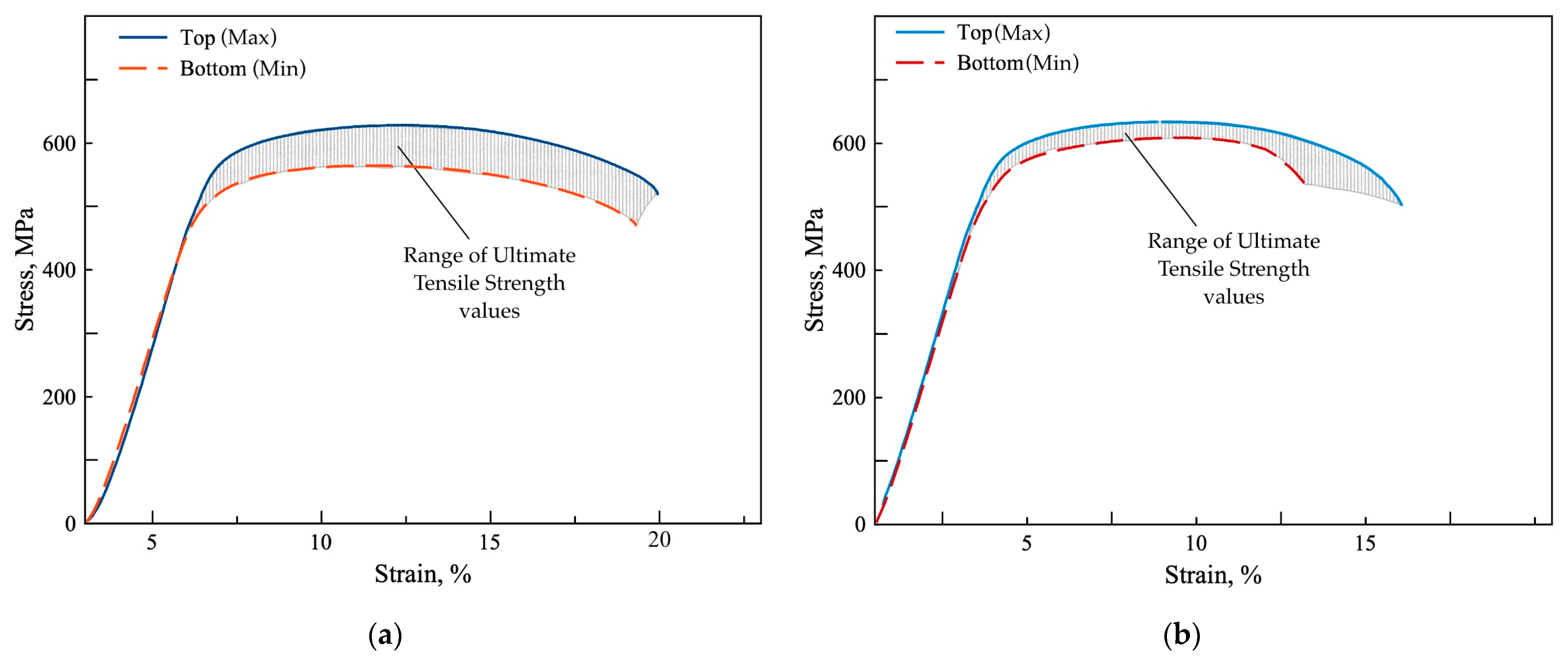
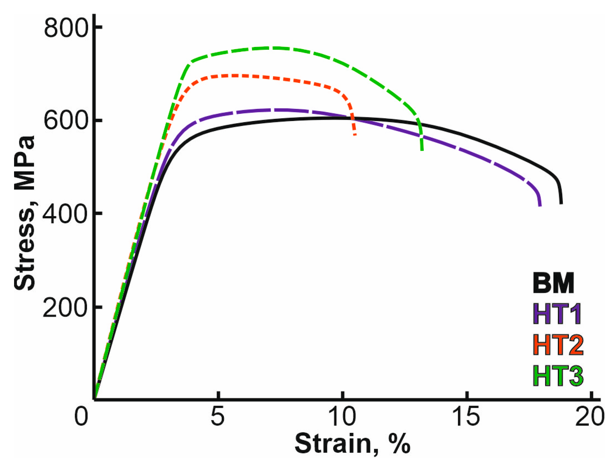
  • The method of wire-feed electron-beam additive manufacturing (WEBAM) allows for the production of a void-free product. However, the resulting material exhibits significantly reduced mechanical properties compared to those required for the Ti–4Al–3V alloy. This is attributed to the absence of active cooling and the complex printing path, which resulted in a material with an ultimate strength ranging from 582 to 632 MPa and a degree of anisotropy in mechanical properties reaching 7%.
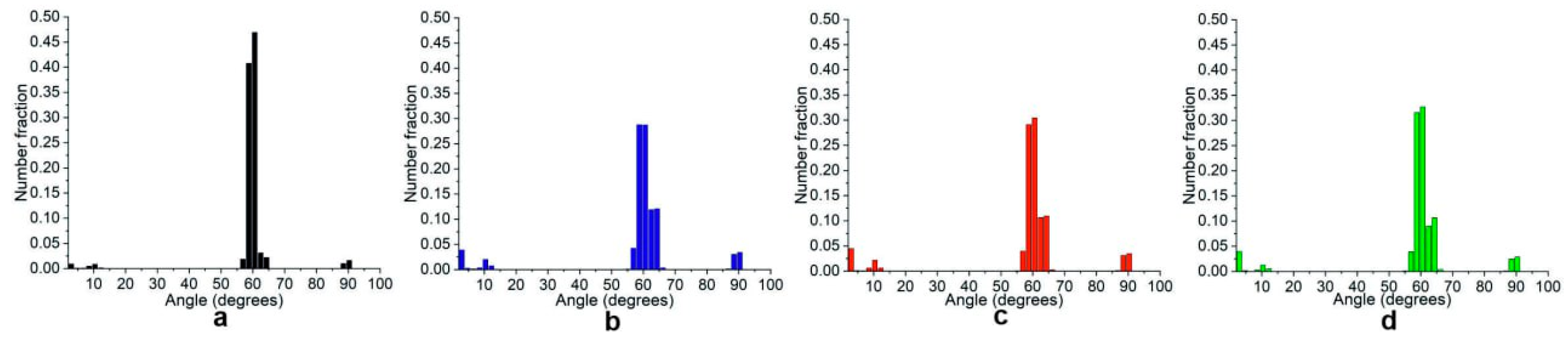
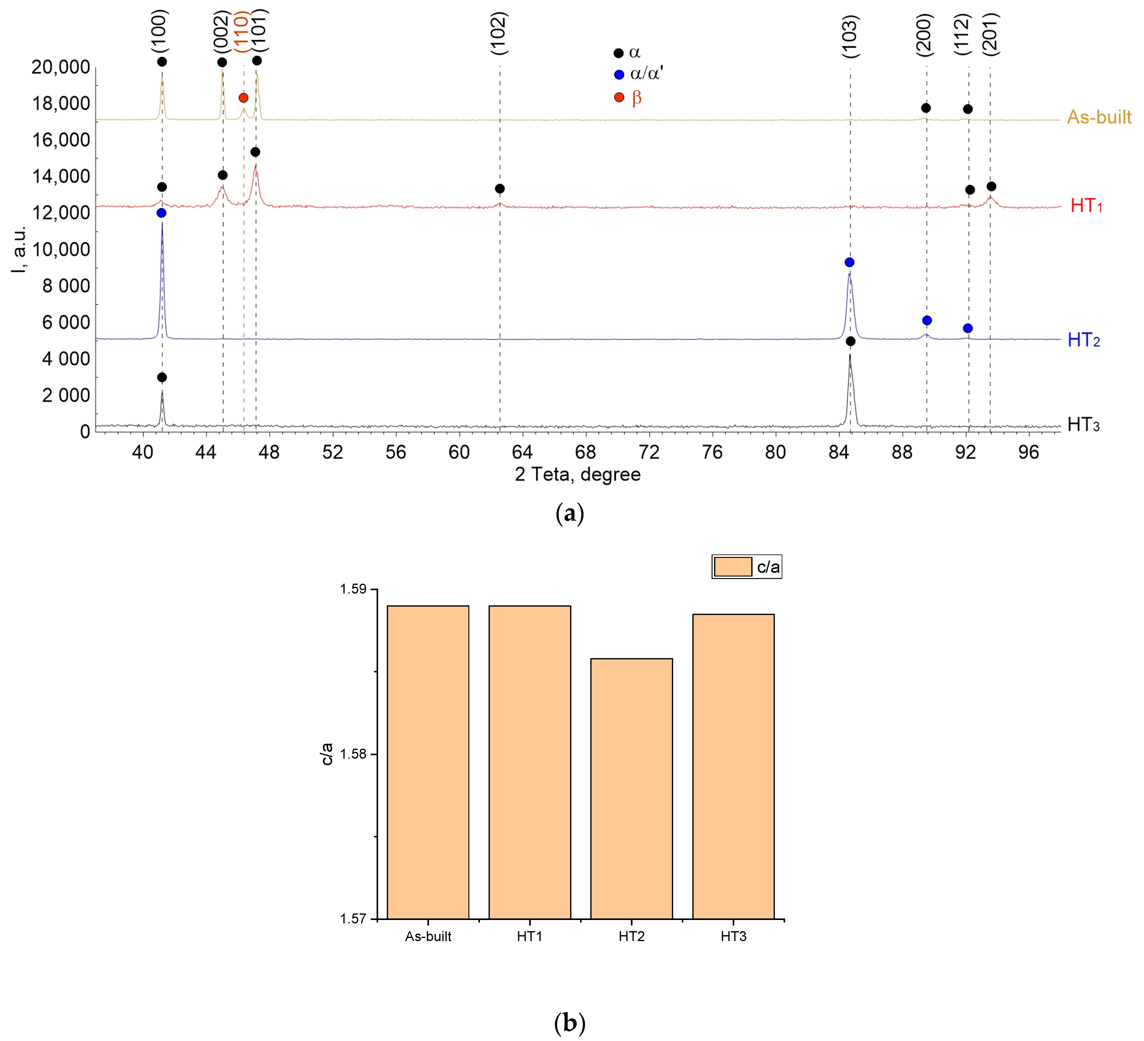
  • The application of heat treatment in the form of subtransus annealing at 940 °C (HT1) resulted in β→α″ transformation and only a slight increase in the UTS. The degree of anisotropy was reduced to 4.5%.
  • Quenching in water after holding at 940 °C for 1 h (HT2) was observed to result in an increase in tensile strength by 11–20% due to β→α′ transformation and deformation twinning because of high transformation-induced stresses. Reduction in the degree of strength anisotropy by 1.3% was due to the formation of a modified microstructure.
  • The quenching followed by annealing at 540 °C (HT3) resulted in the decomposition of α′-Ti into α and fine β particles, preferentially inside the deformation twins, which, on the one side, caused both dispersion and grain boundary strengthening, leading to tensile strength improvement, and on the other side, served to relieve the transformation-induced stresses.

Author Contributions

Conceptualization, S.T., E.K., A.C. and A.M.K.; methodology, S.T., V.R., E.M., A.P. and N.S.; validation, S.T., A.C., E.M. and A.P.; formal analysis, S.T., V.R., E.M., A.P. and N.S.; investigation, D.G., E.M., A.P. and N.S.; resources, V.R.; data curation, A.C.; writing—original draft preparation, S.T., A.C. and D.G.; writing—review and editing, S.T. and D.G.; supervision, E.K.; project administration, E.K. and A.M.K.; funding acquisition, E.K. All authors have read and agreed to the published version of the manuscript.

Funding

This study was carried out under the agreement for the provision of grant funding from the federal budget for large scientific projects in priority areas of scientific and technological development of the Russian Ministry of Science and Higher Education No. 075-15-2024-552.

Data Availability Statement

The original contributions presented in the study are included in the article, further inquiries can be directed to the corresponding author.

Acknowledgments

The authors are thankful to Yuri Kushnarev for his help in WEBAM fabrication of the pressure vessel.

Conflicts of Interest

The authors declare no conflicts of interest.

References

  1. Milewski, J.O. Trends in AM, Government, Industry, Research, Business BT-Additive Manufacturing of Metals: From Fundamental Technology to Rocket Nozzles, Medical Implants, and Custom Jewelry; Milewski, J.O., Ed.; Springer International Publishing: Cham, Switzerland, 2017; pp. 255–292. ISBN 978-3-319-58205-4. [Google Scholar]
  2. Manoj, A.; Rao, M.A.; Basha, M.M.; Basha, S.M.; Sankar, M.R. State of Art on Wire Feed Additive Manufacturing of Ti-6Al-4V Alloy. Mater. Today Proc. 2020, 26, 2608–2615. [Google Scholar] [CrossRef]
  3. Zhang, Y.; Jarosinski, W.; Jung, Y.-G.; Zhang, J. 2-Additive Manufacturing Processes and Equipment. In Additive Manufacturing; Zhang, J., Jung, Y.-G., Eds.; Butterworth-Heinemann: Oxford, UK, 2018; pp. 39–51. ISBN 978-0-12-812155-9. [Google Scholar]
  4. Kanazawa, M.; Iwaki, M.; Minakuchi, S.; Nomura, N. Fabrication of Titanium Alloy Frameworks for Complete Dentures by Selective Laser Melting. J. Prosthet. Dent. 2014, 112, 1441–1447. [Google Scholar] [CrossRef] [PubMed]
  5. Hrabe, N.; Gnäupel-Herold, T.; Quinn, T. Fatigue Properties of a Titanium Alloy (Ti–6Al–4V) Fabricated via Electron Beam Melting (EBM): Effects of Internal Defects and Residual Stress. Int. J. Fatigue 2017, 94, 202–210. [Google Scholar] [CrossRef]
  6. Fuchs, J.; Schneider, C.; Enzinger, N. Wire-Based Additive Manufacturing Using an Electron Beam as Heat Source. Weld. World 2018, 62, 267–275. [Google Scholar] [CrossRef]
  7. Chaturvedi, M.; Scutelnicu, E.; Rusu, C.C.; Mistodie, L.R.; Mihailescu, D.; Subbiah, A.V. Wire Arc Additive Manufacturing: Review on Recent Findings and Challenges in Industrial Applications and Materials Characterization. Metals 2021, 11, 939. [Google Scholar] [CrossRef]
  8. Demir, A.G. Micro Laser Metal Wire Deposition for Additive Manufacturing of Thin-Walled Structures. Opt. Lasers Eng. 2018, 100, 9–17. [Google Scholar] [CrossRef]
  9. Wanjara, P.; Watanabe, K.; de Formanoir, C.; Yang, Q.; Bescond, C.; Godet, S.; Brochu, M.; Nezaki, K.; Gholipour, J.; Patnaik, P. Titanium Alloy Repair with Wire-Feed Electron Beam Additive Manufacturing Technology. Adv. Mater. Sci. Eng. 2019, 2019, 3979471. [Google Scholar] [CrossRef]
  10. Wang, J.; Lin, X.; Wang, J.; Yang, H.; Zhou, Y.; Wang, C.; Li, Q.; Huang, W. Grain Morphology Evolution and Texture Characterization of Wire and Arc Additive Manufactured Ti-6Al-4V. J. Alloys Compd. 2018, 768, 97–113. [Google Scholar] [CrossRef]
  11. Lin, J.J.; Lv, Y.H.; Liu, Y.X.; Xu, B.S.; Sun, Z.; Li, Z.G.; Wu, Y.X. Microstructural Evolution and Mechanical Properties of Ti-6Al-4V Wall Deposited by Pulsed Plasma Arc Additive Manufacturing. Mater. Des. 2016, 102, 30–40. [Google Scholar] [CrossRef]
  12. Kalashnikov, K.N.; Kalashnikova, T.A.; Gurianov, D.A. The Effect of the Ti-6Al-4V Titanium Alloy Cylindrical Sample 3D-Printing Trajectory on the Structure and Mechanical Properties. AIP Conf. Proc. 2020, 2310, 20131. [Google Scholar] [CrossRef]
  13. Fortuna, S.V.; Gurianov, D.A.; Kalashnikov, K.N. Directional Solidification Features of Nickel-Based Superalloy in the Electron Beam Additive Manufacturing Process. AIP Conf. Proc. 2019, 2167, 020107. [Google Scholar]
  14. Zhang, Y.; Feng, L.; Zhang, T.; Xu, H.; Li, J. Heat Treatment of Additively Manufactured Ti-6Al-4V Alloy: Microstructure and Electrochemical Properties. J. Alloys Compd. 2021, 888, 161602. [Google Scholar] [CrossRef]
  15. Venkatesh, B.D.; Chen, D.L.; Bhole, S.D. Effect of Heat Treatment on Mechanical Properties of Ti–6Al–4V ELI Alloy. Mater. Sci. Eng. A 2009, 506, 117–124. [Google Scholar] [CrossRef]
  16. Wang, S.C.; Aindow, M.; Starink, M.J. Effect of self-accommodation on α/αʹ boundary populations in pure titanium. Acta Mater. 2003, 51, 2485–2503. [Google Scholar] [CrossRef]
  17. Chung, C.C.; Wang, S.W.; Chen, Y.C.; Ju, C.P.; Lin, J.H.C. Effect of cold rolling on structure and tensile properties of cast Ti-7.5Mo alloy. Mater. Sci. Eng. A 2015, 631, 52–66. [Google Scholar] [CrossRef]
  18. Leuders, S.; Thone, M.; Riemer, A.; Niendorf, T.; Troster, T.; Richard, H.A.; Maier, H.J. On the mechanical behaviour of titanium alloy TiAl6V4 manufactured by selective laser melting: Fatigue resistance and crack growth performance. Int. J. Fatig. 2013, 48, 300–307. [Google Scholar] [CrossRef]
  19. Vahidshad, Y.; Khodabakhshi, A.H. Effect of Solution Treatment and Aging Temperature on α′ and Ti3Al(α2) Phase Formation and Mechanical Properties of Water-Quenched Ti–6Al–4V. Metallogr. Microstruct. Anal. 2022, 11, 59–71. [Google Scholar] [CrossRef]
  20. Callegaria, B.; Marçola, J.V.; Aristizabal, K.; Soldera, F.A.; Mücklich, F.; Pinto, H.C. Effect of microstructure on Ti3Al precipitation during ageing of Ti-6Al-4V alloy. MATEC Web Conf. 2020, 321, 12014. [Google Scholar] [CrossRef]
  21. Zykova, A.; Panfilov, A.; Vorontsov, A.; Shmakov, V.; Savchenko, N.; Gurianov, D.; Gusarenko, A.; Utyaganova, V.; Krasnoveikin, V.; Tarasov, S. Microstructural and phase evolution of Ti6Al4V in electron beam wire additive manufacturing and on the subtransus quenching and normalization. Mater. Sci. Eng. A 2024, 898, 146384. [Google Scholar] [CrossRef]
  22. Williams, J.C.; Sommer, A.W.; Tung, P.P. The influence of oxygen concentration on the internal stress and dislocation arrangements in α titanium. Metall. Mater. Trans. B 1972, 3, 2979–2984. [Google Scholar] [CrossRef]
  23. Neeraj, T.; Mills, M.J. Short-range order (SRO) and its effect on the primary creep behavior of a Ti–6wt.% Al alloy. Mater. Sci. Eng. A 2001, 319, 415–419. [Google Scholar] [CrossRef]
  24. De Formanoir, C.; Martin, G.; Prima, F.; Allain, S.Y.P.; Dessolier, T.; Sun, F.; Vivès, S.; Hary, B.; Bréchet, Y.; Godeta, S. Microme-chanical behavior and thermal stability of a dual-phase α+α’ titanium alloy produced by additive manufacturing. Acta Mater. 2019, 162, 149–162. [Google Scholar] [CrossRef]
Figure 1. Schematic representation of (a) wire electron beam additive manufacturing (WEBAM), (b) the appearance of a hemisphere made of Ti–4Al–3V alloy, (c) diagram, (d) the appearance of the titanium alloy hemisphere after cutting out the experimental samples, and (e) the assembled and machined high-pressure vessel. Samples 1, 2, 3, and 4 were intended for tensile testing. Samples 5 and 6 were used for preparing metallographic views and XRD.
Metals 14 01379 g001
Figure 2. The process for the spherical vessel prototype production involving the combined use of (a,b) wire-feed additive electron beam manufacturing, (c,d) machining, (e) electron beam welding, and (f) the subsequent helium leakage and (g,h) pressure leakage testing.
Metals 14 01379 g002
Figure 3. Macrostructure (a) and microstructure (b) of a large-sized sample of a high-pressure spherical vessel made from Ti–6Al–4V alloy. (c) of a large-sized sample of a high-pressure spherical vessel made from Ti–6Al–4V alloy at 50 nm.
Metals 14 01379 g003
Figure 4. Tensile stress–strain curves obtained from testing the as-built samples (a) with the tensile axis oriented along the vertical building direction (sample 2, 3) and (b) along the horizontal layer deposition direction (samples 1, 4).
Metals 14 01379 g004
Figure 5. Microstructures of (a) annealed HT1, (b) quenched HT2, and (c) quenched/annealed HT3 Ti–4Al–3V WEBAM samples.
Metals 14 01379 g005
Figure 6. EBSD grain orientation maps in (a,b) as-built, (c,d) annealed HT1, (e,f) quenched HT2, and (g,h) quenched/annealed HT3 Ti–4Al–3V samples cut from the WEBAM-fabricated spherical pressure vessel.
Metals 14 01379 g006
Figure 7. Grain boundary α-Ti misorientation angle distributions for (a) as-built, (b) annealed HT1, (c) quenched HT2, and (d) quenched/annealed HT3 Ti–4Al–3V WEBAM samples.
Metals 14 01379 g007
Figure 8. Stress–strain curves of heat-treated specimens with tensile axis along the layer deposition direction compared to the as-built spherical pressure vessel material.
Metals 14 01379 g008
Figure 9. (a) X-ray phase analysis data of titanium alloy samples in the as-built state (BM), after annealing at 940 °C (HT1), quenching (HT2), and after quenching with subsequent annealing (HT3). (b) Lattice parameter ratio c/a for α/α′-Ti phases.
Metals 14 01379 g009
Figure 10. TEM images of WEBAM Ti–4Al–3V as-built samples. Bright-field (a,e) and dark-field (c,d) images. The dark-field images are obtained using the −101α and 011β reflections shown in the SAED pattern (b), respectively.
Metals 14 01379 g010
Figure 11. TEM images of WEBAM Ti–4Al–3V HT1-annealed samples. (a,b) Bright-field and (d) dark-field images. The dark-field images were obtained using the 002α and 011β/111α′ reflections shown in the SAED pattern (c), respectively.
Metals 14 01379 g011
Figure 12. TEM images of WEBAM Ti–4Al–3V HT2-quenched samples. (a,d) Bright-field and (c) dark-field images. The dark-field images were obtained using the 100α/α′ reflection shown in the SAED pattern (b), respectively. (d) is the bright-field image of a twinned α-grain.
Metals 14 01379 g012
Figure 13. TEM images of WEBAM Ti–4Al–3V HT3 samples. (a,b) Bright-field and (d,e) dark-field images. The dark-field images are obtained using the (3-2-1)α and (0-11)β reflections shown in the SAED pattern (c), respectively. The SAED pattern is obtained from the (b) area.
Metals 14 01379 g013
Figure 14. TEM images of WEBAM Ti–4Al–3V HT3 samples. (a) Bright-field and (c) dark-field images. The dark-field image was obtained using the 110αd′ reflection shown in the SAED pattern (b), respectively.
Metals 14 01379 g014
Table 1. Chemical composition of phases of the as-built (initial) Ti–4Al–3V alloy phases (wt. %).
PhasesAlTiV
α5.87 ± 2.0991.34 ± 3.282.78 ± 1.67
β1.44 ± 0.6577.74 ± 3.4620.82 ± 3.18
Table 2. Chemical composition of phases in the alloy HT1-annealed Ti–4Al–3V (wt. %).
PhasesAlTiV
α4.47 ± 0.4193.17 ± 0.622.09 ± 0.36
α″/β3.32 ± 0.7089.89 ± 1.676.79 ± 2.26
Disclaimer/Publisher’s Note: The statements, opinions and data contained in all publications are solely those of the individual author(s) and contributor(s) and not of MDPI and/or the editor(s). MDPI and/or the editor(s) disclaim responsibility for any injury to people or property resulting from any ideas, methods, instructions or products referred to in the content.

