Article

Influence of Cold-Rolling Processes on the Dimensional Accuracy and Roughness of Small-Diameter Thick-Walled Seamless Tubes

1
State Key Laboratory for Advanced Metals and Materials, University of Science and Technology Beijing, Beijing 100083, China
2
HBIS Group Research Institute, Shijiazhuang 050018, China
3
College of Materials Science and Engineering, Chongqing University of Technology, Chongqing 400054, China
*
Authors to whom correspondence should be addressed.
Metals 2024, 14(11), 1297; https://doi.org/10.3390/met14111297
Submission received: 21 September 2024 / Revised: 28 October 2024 / Accepted: 31 October 2024 / Published: 16 November 2024

Abstract

:
Cold pilgering is widely utilized in high-end applications for the precise shaping of seamless tubes due to its capacity for large deformation, which reduces the number of deformation processes and shortens production cycles. However, there is a gap in the research on the cold pilgering of small-diameter, thick-walled seamless tubes, specifically those with an outer diameter–wall thickness ratio of ≤3. In this study, cold pilgering tests were performed on Cr-Mo-V hot-working die steel small-diameter thick-walled tubes. It was discovered that increasing the feed rate results in greater deviations in both inner diameter and wall thickness, although it has little effect on inner wall roughness. In contrast, increasing wall thickness reduction leads to higher wall thickness deviation but reduces inner surface roughness without significantly affecting inner diameter deviation. The study also found that a decrease in the initial inner wall roughness before pilgering results in improved final roughness. Under optimal conditions, the average inner surface roughness Sa can reach 0.177 μm, and small-diameter thick-walled seamless tubes with deviations in the inner diameter and wall thickness of 0.05 mm and 0.03 mm, respectively, are obtained. After tempering at 600 °C, the tensile strength (Rm) and yield strength (Rp0.2) of the cold-pilgered tube reach 1092 MPa and 947 MPa, respectively, and the elongation (δ5%) and impact energy (AkU) increase to 20.4% and 61.5 J, respectively.

1. Introduction

Small-diameter thick-walled seamless tube refers to a steel tube with a small ratio of outer diameter to wall thickness, which is widely used in nuclear power, petrochemicals, geological drilling, and weapons [1,2,3]. The fabrication methods for small-diameter thick-walled seamless tubes primarily include hot rolling, cold pilgering, and deep hole drilling. Hot rolling typically results in suboptimal surface quality, necessitating further post-processing [4]. Deep hole drilling leads to substantial material wastage and may cause damage to the inner surface [5]. In contrast, cold pilgering offers superior dimensional control and enhanced surface quality for small-diameter thick-walled tubes, eliminating the need for secondary processing [6,7,8,9].
Cold pilgering is widely employed as a cold-working process for high-quality seamless tubes, including those made from stainless steel, titanium alloys, and zirconium alloys [10,11,12]. These tubes typically require superior mechanical properties, high surface quality, and tight dimensional tolerances. For zirconium alloy tubes used in nuclear reactor fuel cladding and titanium alloy tubes used in aircraft hydraulic lines, the permissible variations in outer and inner diameters, as well as wall thickness, are in the order of 10 μm. It is critical for tube manufacturers to select appropriate fabrication conditions to meet these stringent dimensional requirements. Process conditions such as feed rate, stroke speed, and turn angle significantly affect the dimensional accuracy of tubes subjected to cold pilgering [13,14,15].
However, cold pilgering is mainly used to prepare precision thin-walled seamless tubes with an outer diameter–wall thickness ratio of ≥5. There are no relevant research or literature reports on cold pilgering of small-diameter thick-walled seamless tubes with an outer diameter–wall thickness ratio of ≤3. The primary issue arises from the substantial reduction in tube-wall-thickness-per-unit distance during short-stroke rolling, where the rolling mill is unable to generate sufficient rolling force according to the Shevakii-proposed calculation method [16]. Conversely, long-stroke rolling mills are prone to problems such as mandrel vibration and fracture [17].
In our previous study, small-hole seamless steel tubes with a diameter–thickness ratio of less than 3 were manufactured using a novel cold-rolling process [18,19]. Compared to traditional seamless pipe cold rolling, the new cold-rolling process enhances inner wall quality by regulating the deformation ratio of the inner diameter to wall thickness and employing large deformation rolling. The process parameters for pilger cold-rolled seamless steel tubes are predominantly established through empirical methods. Establishing the relationship between processing parameters and tube quality constitutes a critical approach to the production of high-quality tubes. Deng et al. [20,21] utilized a 75VMR-type mill to produce Zr-4 alloy tubes with dimensions of 44.5 mm × 7.55 mm for nuclear reactor cladding and developed a theoretical model to predict the fatigue life of cold-pilgered tubes using finite element simulation and experimental methods. Yagiz et al. [22] found that roller deformation significantly affects the contact area length, rolling force, and the accuracy of the finished tube. By modeling the rollers as elastic bodies and incorporating them into finite element simulations, their experiments demonstrated that this model more accurately predicts the rolling force and stress–strain states during the two-roller pilgering process. Wang et al. [23,24] employed a three-roller pilger mill to produce thin-walled GH4145 tubes with dimensions of 26 mm × 1 mm for aerospace engines, finding that the release of residual stresses during the annealing process reduced ovality. Abe et al. [25] analyzed the pilgering process conditions affecting tube size accuracy and ovality, revealing that feed rate and rotation angle during pilgering have a significant impact on the dimensions of the finished tube, whereas stroke speed has a minimal effect. To achieve the cold pilgering of small-caliber thick-walled tubes with an outer diameter–wall thickness ratio of ≤3, this paper investigates cold-pilgering experiments on Cr-Mo-V steel. The effects of feed rates, wall thickness reduction, and initial inner wall roughness of the mother tube on the precision of cold-pilgered tubes ( 33 mm × 11 mm) were examined. Additionally, the impact of post-pilgering heat treatment on the microstructure and mechanical properties of the finished tubes was analyzed. It can be seen that the process parameters are the key to affecting the quality of the pilgering tube, including feed rate, dimensional deviations, stroke speed, and post-treatment.

2. Experimental Section

2.1. Experimental Materials

The blank tube material was made of Cr-Mo-V hot-working die steel developed independently by our team, and its microstructure was tempered martensite. The detailed chemical composition of the blank tube material is shown in Table 1.

2.2. Cold-Rolling Experiments

An LG40 pilger mill (Changzhou Xingtong Machinery Manufacturing Factory, Changzhou, China) was used for the pilgering experiments, a picture of which is shown in Figure 1.
To investigate the effect of feed rate, a mother tube with an outer diameter (OD) of = 4 7 mm and a wall thickness of δ = 14.5 mm was subjected to pilger experiments with feed rates of 2, 3, and 4 mm/stroke, respectively, and a stroke speed of 60 stokes/min and a rotation angle of 53°/stroke. The cold-pilgered tubes were 33 mm in outer diameter and 11 mm in wall thickness. To measure the dimensional deviation, the minimum wall thickness or inner diameter of the cold-pilgered tube was se as the starting point (i.e., 0°), and dimensional deviations were measured at intervals of 30°, i.e., at 0°, 30°, 60°, 90°, 120°, and 150°.
To evaluate the effect of wall thickness reduction, mother tubes with an inner diameter (ID) of = 1 8 mm were subjected to cold-pilgering experiments. The wall thicknesses (WT) of the mother tubes were 13.5, 14.5, and 15.5 mm, respectively, giving wall thickness reductions of 2.5, 3.5, and 4.0 mm, respectively. The cold-pilgering experiments were carried out under a feed rate of 3 mm/stroke, stroke speed of 60 stokes/min, and a rotation angle of 53°/stroke. The cold-pilgered tubes have the specification of 33 × 11 mm.
To investigate the effect of initial inner surface roughness (Sa), mother tubes with different Sa of 0.772, 1.151, and 1.480 μm were subjected to cold-pilgering processing. The experiments were carried out at the feed rate of 3 mm/stroke, wall thickness reduction of 3.5 mm, stroke speed of 60 strokes/min, and rotation angle of 53°/stroke to obtain cold-pilgered tubes with the specification of ϕ 33 × 11 mm.
To evaluate the morphology and roughness of the inner surface of the seamless tubes, a MicroXAM-3D white light interferometer (MicroXAM-3D, KLA Instruments, Milpitas, CA, USA) was employed in this work, and the inner wall roughness was characterized by using the following three formulas:
S a = 1 A | Z x , y | d x d y
S q = 1 A Z 2 x , y d x d y
S z = S p + S v
where Sa is the arithmetic mean of the absolute height differences in each point within the defined observation area A; Sq refers to the mean root square of the height of each point within the observation area A, which is equivalent to the standard deviation of height; while Sz corresponds to the sum of the maximum peak height (Sp) and the maximum valley depth (Sv) within the defined observation area A. In this study, Sa, Sq, and Sz are all obtained from calculations performed by the Gwyddion software (version 2.61) based on Formulas (1)–(3). The basis for the surface roughness measurement is the standard “GB/T1031-2009 Geometrical product specifications (GPS)—Surface texture: Profile method—Surface roughness parameters and their values” [26]. All the values for the above test presented in this study are averages obtained from the rolled tubes (with a length of 100 mm) measured at positions of 30 mm, 60 mm, and 90 mm. Subsequent measurements were then taken at 30°, 60°, 90°, 120°, and 150° in a clockwise direction, as seen in Figure 2. At each of the three measurement positions, the inner diameter, wall thickness, and roughness were measured three times.

2.3. Heat Treatment Experiment Before and After Pilgering

First, the mother tube undergoes quenching and tempering treatment, followed by the cold-pilgering process described in Section 2.2. Finally, tempering is performed on the cold-pilgered tubes with the lowest dimensional deviations and inner surface roughness (Sa). The tubes were heated to 1000 °C for 1 h, quenched to room temperature in water, then tempered for 3 h and cooled to room temperature before pilgering. Then, the pilgered tubes were tempered at different temperatures for 3 h and cooled in air. The schematic diagram of the heat treatment process is shown in Figure 3. The tensile tests were conducted according to the standard “GB/T228-2021: Metallic materials—Tensile testing—Part 1: Method of test at room temperature” [27]. Figure 4 is the schematic diagram of tensile specimens. The tensile specimens were cut by electric discharge wire and the tests were performed at room temperature using a CMT4105 electronic universal testing machine (Jinan Liangong Testing Technology Co., Ltd., Jinan, China). The tensile rate was set at 2 mm/min. Each process underwent three tests for data accuracy.

3. Results and Discussion

3.1. The Effects of Feed Rate

Figure 5 shows the dependence of wall thickness deviation at different angles on the feed rates. It can be seen that the wall thickness tolerance of the mother tube is approximately 0.07–0.08 mm. Under the feed rate of 2 mm/stroke, the wall thickness tolerance of the cold-pilgered tube turns to 0.020–0.025 mm. Also, the wall thickness deviation increases continuously as the feed rate increases. When the feed rate increases to 4 mm/stoke, the maximum wall thickness deviation is observed, giving a value of 0.05 mm. Additionally, the maximum wall thickness deviation also continues to increase as the feed rate increases.
Figure 6 shows the dependence of inner diameter deviation at different angles on the feed rates. It is observed that the inner diameter deviation of the blank tube is approximately 0.05–0.06 mm before rolling. Under the feed rate of 2 mm/stroke, the inner diameter deviation of the cold-pilgered tube can decrease to 0.02–0.03 mm. As the feed rate increases, the inner diameter deviation continues to increase. Under the feed rate of 4 mm/stoke, the maximum inner diameter deviation of 0.06 mm is obtained. As the feed rate increases, the rolling force and friction between the workpiece and the dies also increase due to the higher relative speed. This results in uneven material flow, leading to varying amounts of material being squeezed at different locations along the tube wall and, consequently, increased wall thickness variation [28,29].
Figure 7 shows the inner surface morphologies of the cold-pilgered tubes under different feed rates. It also shows the roughness measurement sampling diagram, and the red area is the roughness measurement surface: AD: axial direction; RD: radial direction; TD: tangential direction as seen in Figure 7d. As the feed rate increases from 2 mm to 4 mm, the average inner surface roughness Sa of the cold-pilgered tube increases from 0.177 μm to 0.210 μm, as presented in Table 2. As the feed rate gradually increases, the maximum height difference between peaks and valleys on the inner surface is at the level of 1.902–2.006 μm, which is relatively stable. Meanwhile, the Sq is also basically stable, in the range of 0.221–0.266 μm. Based on the above, we can see that the feed rate has a relatively small impact on the inner surface roughness of the cold-pilgered tubes.

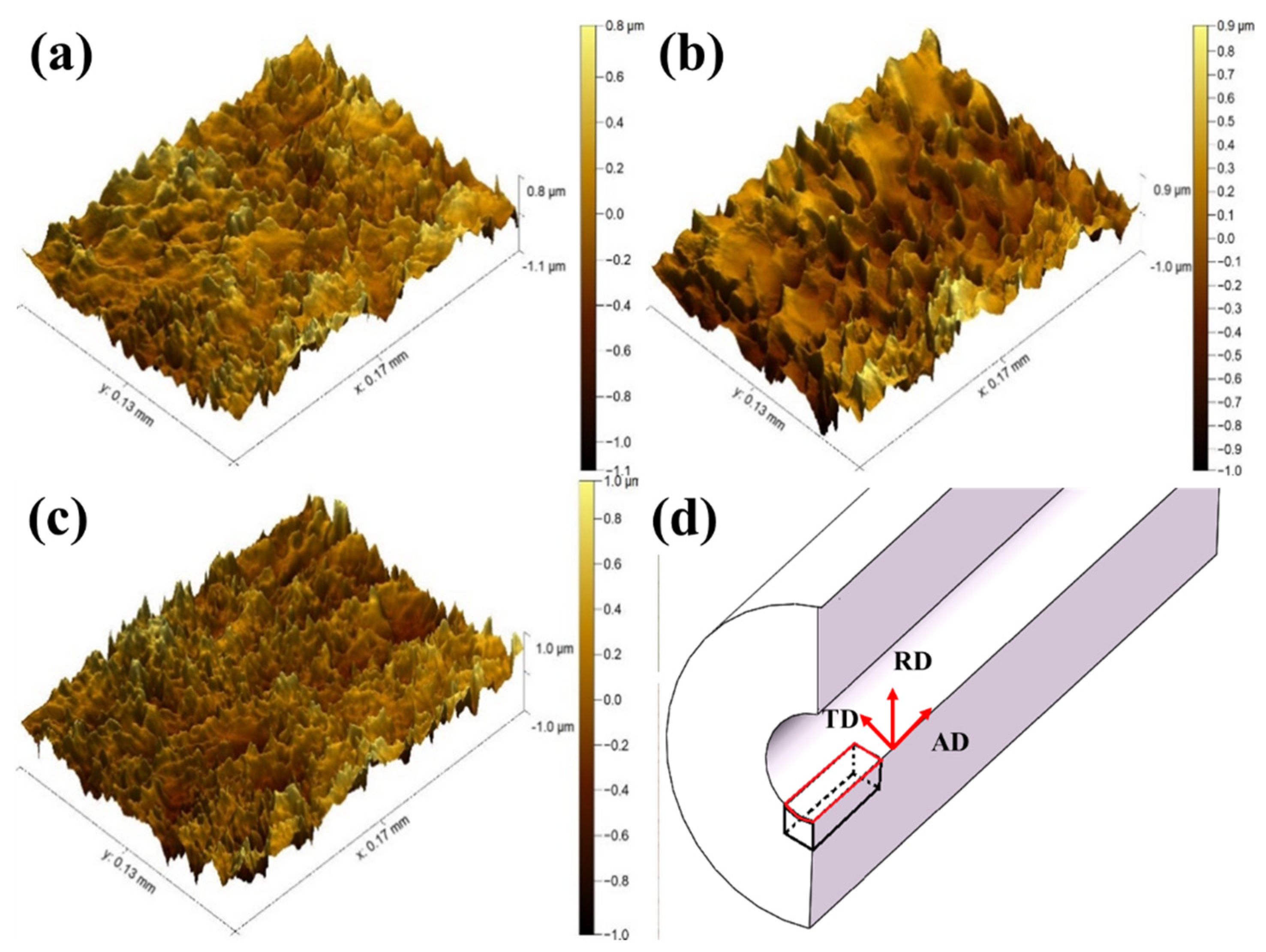
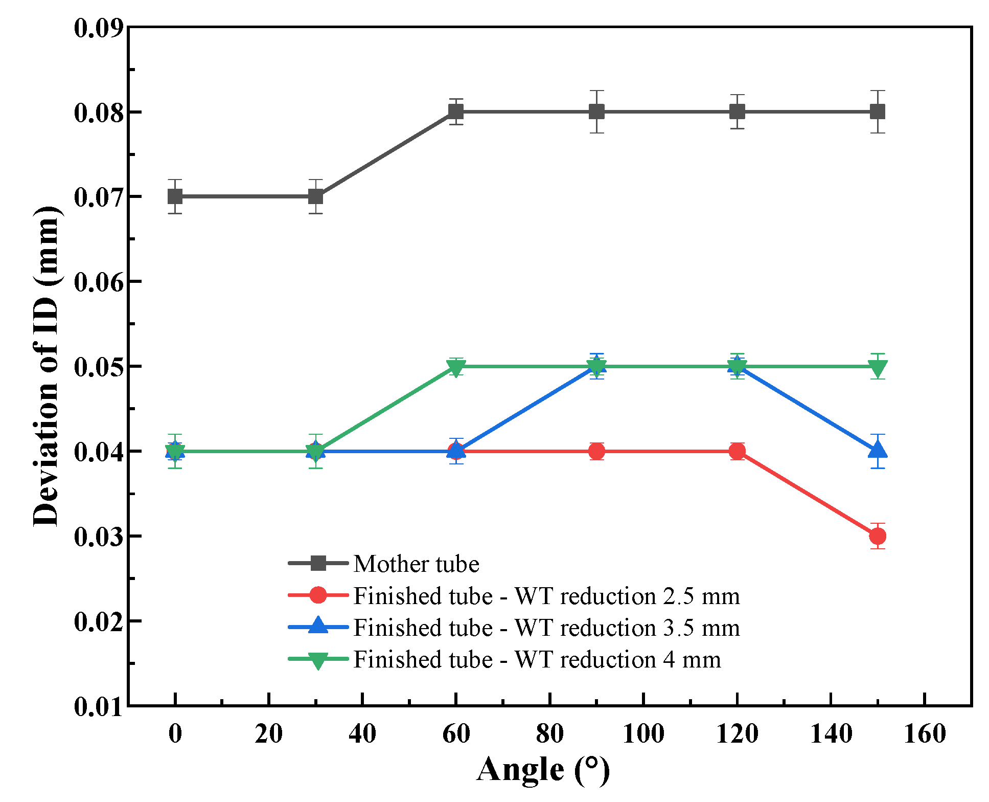
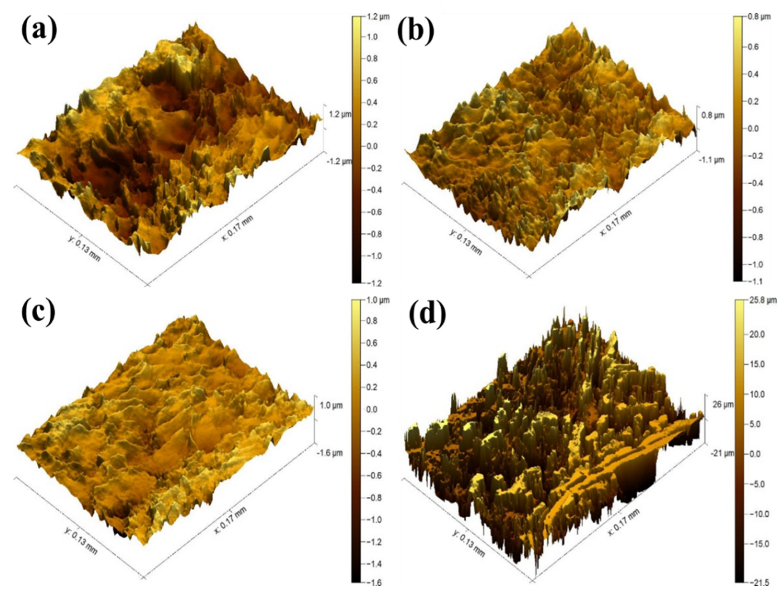
3.2. The Effects of Wall Thickness Reduction

Figure 8 shows the dependence of wall thickness deviation at different angles of cold-pilgered tubes on wall thickness reduction. It can be observed that the wall thickness deviation of the cold-pilgered tubes across the three processes (i.e., exhibiting varying wall thickness reductions) is less than that of the original blank tube. When the wall thickness reduction ranges from 2.5 to 3.5 mm, the maximum wall thickness deviation of the cold-pilgered tube is 0.03 mm; conversely, when the wall thickness reduction is 4 mm, the maximum wall thickness deviation increases to 0.05 mm. Based on the findings, it can be concluded that as the wall thickness reduction increases, the deviation in wall thickness correspondingly escalates.
Figure 9 illustrates the relationship between the inner diameter deviation at various angles and feed rates. The inner diameter deviation of the blank tube is approximately 0.07 to 0.08 mm prior to rolling. With a wall thickness reduction of 2.5 mm, the corresponding inner diameter deviation attains a maximum of 0.04 mm. As the wall thickness reduction further escalates to 4 mm, the inner diameter deviation rises to 0.05 mm. Based on the aforementioned study, it can be concluded that wall thickness reduction has no significant impact on the inner diameter deviation of cold-pilgered tubes.
Figure 10 shows the inner surface morphologies of the cold-pilgered tubes under different wall thickness reductions. It can be seen that as the wall thickness reduction increases from 2 mm to 4 mm, the average height difference between peaks and valleys on the inner surface (i.e., the inner surface roughness Sa) of the cold-pilgered tube decreases from 0.229 μm to 0.174 μm, as presented in Table 3. Nevertheless, when the wall thickness reduction reaches 4 mm, specific regions of the inner surface of the cold-rolled, cold-pilgered tube exhibit a notable increase in surface roughness, with an average Sa of 7.847 μm, which is considerably higher than that observed in other areas. The height difference between peaks and valleys on the inner surface abnormally increased, with a maximum height difference Sz reaching 47.25 μm, as shown in Figure 10d. The reason for this phenomenon may be that under such excessive wall thickness reduction (4 mm), the inner and outer surfaces of the deformation cone shrink simultaneously during the reduction section, but the inner surface shrinks severely and wraps around the core rod in advance.
During the rolling and feeding process, the inner surface of the deformation cone undergoes wear as it separates from the core rod, while the surface of the core rod partially adheres to the inner surface of the deformation cone. Considering the significantly higher hardness of the core rod relative to the blank tube, metal particles detach and adhere during the wall thickness reduction phase, where they are subjected to the combined effects of rolling and axial forces, ultimately leading to excessive surface roughness. As the wall thickness decreases, the contact area between the tube’s inner surface and the mandrel increases. This enhanced contact exerts a polishing or burnishing effect on the inner surface, effectively smoothing surface asperities and diminishing roughness. The intense compressive forces during pilgering refine the surface microstructure through plastic deformation, a process that effectively irons out irregularities on the inner surface, leading to a smoother finish [30].

3.3. The Effect of Initial Inner Surface Roughness

Figure 11 illustrates the inner surface morphologies of tubes exhibiting varying initial inner surface roughness both prior to and following pilgering. It can be observed that the distribution of peaks and valleys on the inner surface of the tubes prior to rolling is relatively uniform, with both peaks and valleys displaying “facet features”, as depicted in Figure 11a,c,e. The Sz obtained from the three micrographs were 2.901 μm, 4.095 μm, and 6.072 μm, respectively, while the corresponding Sq were found to be 0.865 μm, 1.391 μm, and 1.729 μm, respectively. After being subjected to the same rolling processing (i.e., feed rate of 3 mm/stoke, wall thickness reduction of 3.5 mm, feed speed of 60 stokes/min, and rotation angle of 53°), the height difference between the rough peaks and valleys on the inner surface has decreased compared to that before rolling, and the facet features of the peaks and valleys have disappeared. Additionally, the width of the peaks and valleys has decreased, as shown in Figure 11b,d,f. Moreover, it is found that the peaks and valleys turn sharply and the density of peaks and valleys per unit area also increase after rolling. The maximum height difference Sz between the peaks and valleys in the above three micrographs decreases to 1.902 μm, 3.616 μm, and 3.925 μm, respectively. The Sq of the tubes after rolling are 0.238 μm, 0.417 μm, and 0.557 μm, respectively, which are much smaller than that of the tubes before rolling. During the rolling process, the core rod supports the inner surface of the tube, while the tube simultaneously advances axially and rotates in sync with the core rod, resulting in a certain degree of synchronous rotation along the circumferential direction. The reduction in the number of peaks and valleys observed in Figure 11d may be attributed to excessive lubrication between the inner wall of the tube and the core rod during the feed rotation. This leads to relative sliding in the circumferential direction, resulting in an angular difference in rotation between the core rod and the tube. The frictional force causes the deflection of the peaks on the inner surface, where taller peaks obscure some of the shorter peaks, leading to a decrease in peak density as depicted in the figure. Inner surface roughness changes in three tubes before and after rolling, as presented in Table 4. The results regarding small-diameter seamless pipes with a diameter–thickness ratio of ≤3 discussed in this paper are applicable to seamless tubes with similar inner diameter–wall thickness deformation ratios during cold rolling. Further research is necessary for seamless tubes with different deformation ratios.

3.4. Mechanical Properties

Table 5 shows the mechanical properties of the cold-pilgered tubes with different wall thickness reductions along the axial direction. It can be seen that as the wall thickness reduction increases from 2 mm to 3 mm, the yield strength of the entire wall thickness along the rolling direction keeps increasing, and the amplitude also increases continuously. When the wall thickness reduction reaches 3.5 mm, although the overall yield strength increases along the rolling direction, the amplitude slows down, which is consistent with the change in dislocation density in the microstructure. Affected by working hardening, as the wall thickness reduction increases, the elongation and room-temperature (RT) impact energy both decrease continuously.
The cold-pilgered tubes with a wall thickness reduction of 3.5 mm were then tempered at 600 °C, 620 °C, 640 °C, and 660 °C for 4 h. The room-temperature tensile strength, yield strength, elongation, and cross-sectional shrinkage rate were measured, the results of which are shown in Figure 12. It can be observed that after tempering at 640 °C and 660 °C, the room temperature tensile strengths of the cold-pilgered tubes are 988 MPa and 961 MPa, respectively, and the yield strengths are 861 MPa and 837 MPa, respectively. Both these two mechanical properties are lower than the required Rm ≥ 1030 MPa and Rp0.2 ≥ 900 MPa. After heat treatment at 600 °C, the room-temperature tensile strength, the yield strength, the elongation, and the room-temperature impact energy of the sample are approximately 1092 MPa, 947 MPa, 21.2%, and 61.5 J, respectively. The precipitation after tempering has a strong strengthening effect on Cr-Mo-V steel [31,32].

3.5. Microstructures of the Cold-Pilgered Tubes

Figure 13 shows the SEM images of the inner surfaces of the tube before rolling, the cold-pilgered tube, and the tube after 600 °C tempering along the axial direction. It can be seen that the microstructures in all of the three states are tempered martensite. The blank tube before rolling exhibits equiaxed grain, with a relatively small amount of carbides in the microstructure; the grains of the cold-pilgered tube elongate along the rolling direction, and carbides precipitate significantly. The higher diffusion rates at grain boundaries compared to the grain interiors facilitate the easier migration and accumulation of carbide-forming elements at the grain boundaries, resulting in increased carbide precipitation during tempering [33,34]. After tempering at 600 °C, a large amount of carbides precipitate at the grain boundaries.

4. Conclusions

In summary, the following conclusions could be drawn from this work:
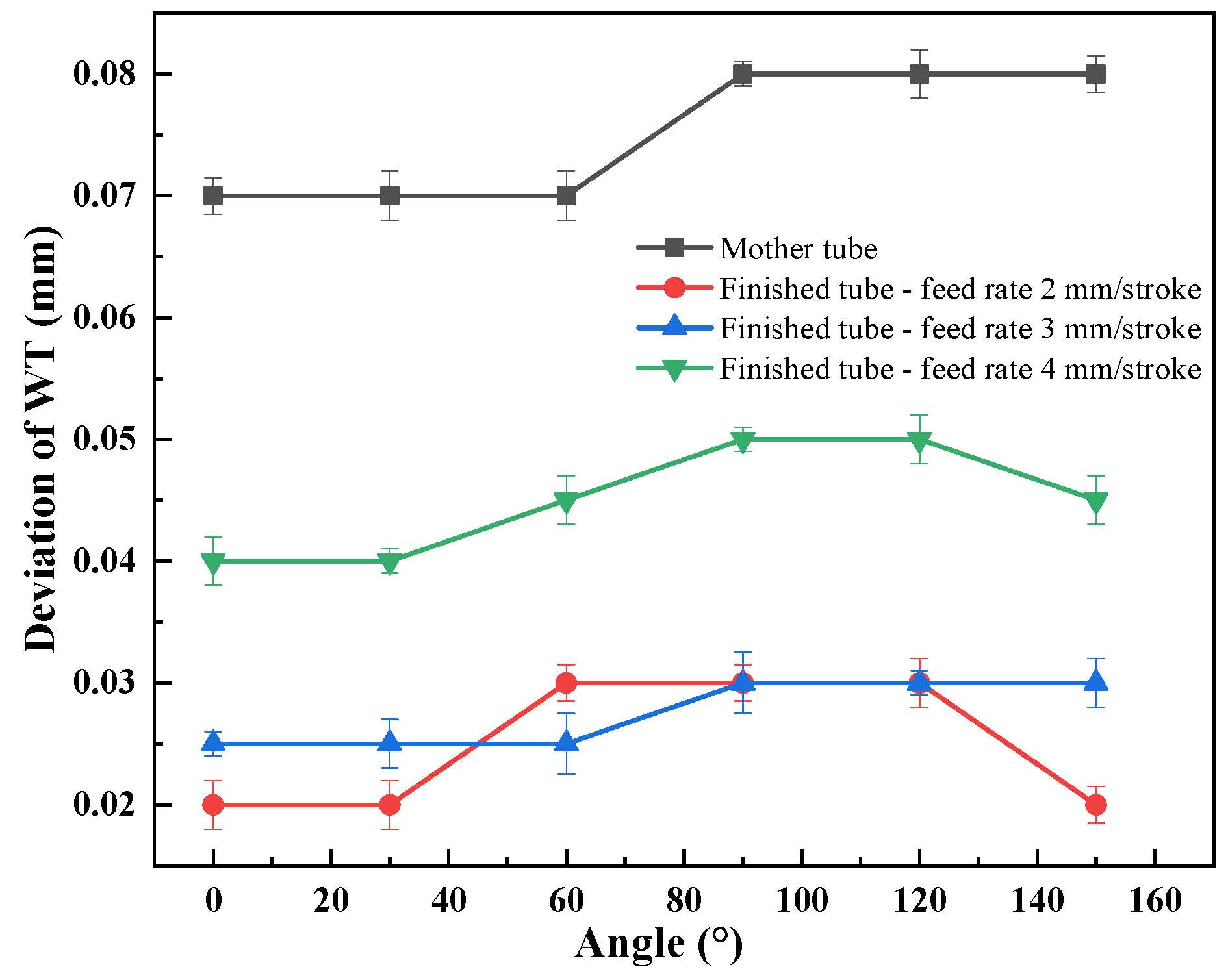
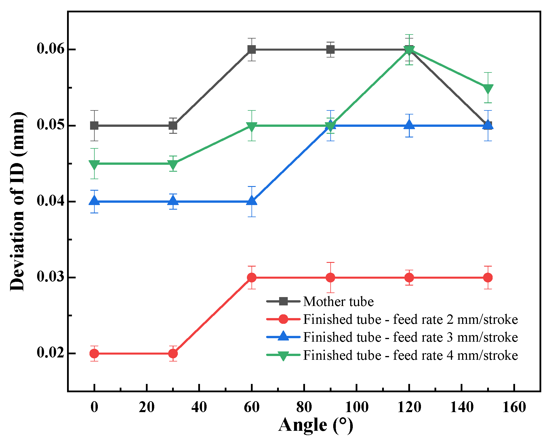
  • As the feed rate increases from 2 mm/stroke to 4 mm/stroke, the wall thickness deviation of the cold-rolled tube rises from 0.02 mm to 0.04 mm, indicating a 100% increase. The inner diameter deviation increases from 0.02 mm to 0.045 mm, reflecting a 125% increase; however, there is no significant effect on the inner wall roughness. When the wall thickness reduction escalates from 2.5 mm to 4 mm, the wall thickness deviation of the cold-rolled tube grows from 0.03 mm to 0.05 mm, corresponding to a 66.7% increase. The inner wall roughness, quantified as Sa, decreases from 0.299 μm to 0.174 μm; however, the effect on inner diameter deviation is not significant. Furthermore, as the initial inner wall Sa reduces from 1.483 μm to 0.772 μm prior to rolling, the inner wall roughness of the cold-rolled tube decreases from 0.451 μm to 0.189 μm.
  • Under the following rolling processing conditions: a wall thickness reduction of 3.5 mm, feed rate of 3 mm/stroke, and initial average inner wall roughness of ≤0.8 μm, high-precision small-diameter thick-walled seamless tubes with an inner diameter deviation of ≤0.05 mm, wall thickness deviation of ≤0.03 mm, and inner average wall roughness Sa of ≤0.2 μm can be obtained.
  • As the wall thickness reduction increases from 2 mm to 3.5 mm, the working hardening degree of the cold-pilgered tubes gradually increases, enhancing the tensile strength and the yield strength to 1181 MPa and 1137 MPa, with increases of 3.87% and 12.35%, respectively. The elongation and impact energy decreases to 12% and 52 J, respectively. After tempering at 600 °C, the tensile strength and yield strength of the tube reach 1092 MPa and 947 MPa, respectively, while the elongation and impact energy elevate to 20.4% and 61.5 J, respectively.

Author Contributions

Conceptualization, X.D. and J.H.; Methodology, P.J. and W.W.; Validation, X.D., C.Z. and J.H.; Investigation, X.D., P.J. and W.W.; Resources, R.L.; Writing—original draft, R.L. and M.M.; Writing—review & editing, X.D., R.L. and M.M.; Supervision, C.Z. and J.H.; Project administration, C.Z. All authors have read and agreed to the published version of the manuscript.

Funding

This research received no external funding.

Data Availability Statement

The original contributions presented in the study are included in the article, further inquiries can be directed to the corresponding author.

Conflicts of Interest

Author Ran Li was employed by HBIS Group Research Institute. The remaining authors declare that the research was conducted in the absence of any commercial or financial relationships that could be construed as a potential conflict of interest.

References

  1. Kharitonov, V.V.; Bogatov, A.A. Efficient Technology for Making Ultra-Thick-Walled Small-Diameter Tubes of Bearing Steel. Metallurgist 2004, 48, 328–334. [Google Scholar] [CrossRef]
  2. Sun, X.; Smith, L.M. External Heating Closed-Volume Thermally Activated Tube Forming: A Fundamentally New Approach for Hydroforming Thick-Walled Tubes. J. Manuf. Process. 2010, 12, 63–66. [Google Scholar] [CrossRef]
  3. Zhao, X.; Deng, Z.; Yu, Z.; Li, T.; Song, X. Magnetic Permeability Perturbation Testing for Internal Axial Cracks in Small-Diameter Thick-Walled Steel Pipes. Appl. Sci. 2023, 13, 7107. [Google Scholar] [CrossRef]
  4. Yuan, G.; Zhang, R.; Zhang, Y.; Kang, J.; Li, Z.; Liu, X.; Wang, J. Heat Transfer Characteristics of a Hot-Rolled Seamless Steel Tube During a Controlled Cooling Process. Steel Res. Int. 2023, 94, 2200150. [Google Scholar] [CrossRef]
  5. Li, B.; Huang, C.; Tang, Z.; Chen, Z.; Liu, H.; Chen, Z.; Niu, J.; Wang, Z. Effect of Drilling Parameters on the Hole Surface Integrity of Low Alloy Steel for Nuclear Power during BTA Deep Hole Drilling. Int. J. Adv. Manuf. Technol. 2023, 127, 565–577. [Google Scholar] [CrossRef]
  6. Musazadeh, M.H.; Vafaei, R.; Mohammad Sharifi, E.; Farmanesh, K. Mechanical Properties, Microstructural Evolution, and the Effect of Friction on the Plastic Flow of the AISI 321 Austenitic Stainless Steel Tube During Cold Pilgering: An Experimental and Simulation Analysis. Met. Mater. Trans. B 2018, 49, 3030–3042. [Google Scholar] [CrossRef]
  7. Zhang, H.Q.; Wang, X.F.; Wei, B.L.; Li, H. Effect of Tooling Design on the Cold Pilgering Behavior of Zircaloy Tube. Int. J. Adv. Manuf. Technol. 2017, 92, 2169–2183. [Google Scholar] [CrossRef]
  8. Abe, H.; Nomura, T.; Kubota, Y. Lubrication of Tube in Cold Pilgering. J. Mater. Process. Technol. 2014, 214, 1627–1637. [Google Scholar] [CrossRef]
  9. Ragger, K.S.; Primig, S.; Daniel, R.; Kaiser, R.; Paal, J.; Mitterer, C.; Buchmayr, B. Cold Pilgering of Duplex Steel Tubes: The Response of Austenite and Ferrite to Excessive Cold Deformation up to High Strains. Mater. Charact. 2017, 128, 257–268. [Google Scholar] [CrossRef]
  10. Azizoğlu, Y.; Sjöberg, B.; Lindgren, L.-E. Modeling of Cold Pilgering of Stainless-Steel Tubes. J. Manuf. Process. 2024, 112, 112–125. [Google Scholar] [CrossRef]
  11. Li, H.; Wei, D.; Zhang, H.; Yang, H.; Liu, H.; Liu, S.; Chu, Z.; Zhang, D. Texture Evolution and Controlling of High-Strength Titanium Alloy Tube in Cold Pilgering for Properties Tailoring. J. Mater. Process. Technol. 2020, 279, 116520. [Google Scholar] [CrossRef]
  12. Deng, S.; Wang, S.; Chen, S.; Zheng, C.; Song, H.; Zhang, S. Texture Evolution of Zircaloy-4 Tube during Cold Pilgering: Operating Mechanism of Q Factor. J. Nucl. Mater. 2024, 589, 154846. [Google Scholar] [CrossRef]
  13. Chu, Z.; Xue, Z.; Zhang, D.; Wang, H.; Li, W.; Liu, R.; Huang, Q. Parameters of Cold Pilgering of Seamless Steel Tube. J. Iron Steel Res. Int. 2019, 26, 593–601. [Google Scholar] [CrossRef]
  14. Mulot, S.; Hacquin, A.; Montmitonnet, P.; Aubin, J.-L. A Fully 3D Finite Element Simulation of Cold Pilgering. J. Mater. Process. Technol. 1996, 60, 505–512. [Google Scholar] [CrossRef]
  15. Musazadeh, M.H.; Mohammad Sharifi, E.; Vafaei, R.; Farmanesh, K. An Experimentally Validated Computational Model of Damage Buildup in the Pilgering of AISI 321 Steel: Influence of Process Parameters. Trans. Indian. Inst. Met. 2020, 73, 1843–1851. [Google Scholar] [CrossRef]
  16. Cheng, H.; Zhao, T.; Hao, J.; Ji, S.; Zhan, J.; Zhang, J. Simulative Computation of Rolling Force in Cold Pilgering Process of High-Accuracy Stainless Steel Pipe. Heavy Mach. 2012, 2, 49–52+61. [Google Scholar]
  17. Lodej, B.; Niang, K.; Montmitonnet, P.; Aubin, J.-L. Accelerated 3D FEM Computation of the Mechanical History of the Metal Deformation in Cold Pilgering of Tubes. J. Mater. Process. Technol. 2006, 177, 188–191. [Google Scholar] [CrossRef]
  18. Li, R.; Zhang, X.; Zhang, C.; Wang, J.; Huang, J. Preparation of high-precision dimension seamless thick-walled pipe by new cold rolling process. Metals 2022, 12, 1761. [Google Scholar] [CrossRef]
  19. Li, R.; Jin, P.; Wang, W.; Zhang, C.; Du, X.; Huang, J. Inner Surface Morphology and Roughness Evolution of Pilgering Thick-Walled Tubes. Materials 2023, 16, 7618. [Google Scholar] [CrossRef]
  20. Deng, S.; Song, H.; Zheng, C.; Zhao, T.; Zhang, S.; Nielsen, K.B. Selection of Deformation Modes and Related Texture Evolution in Zircaloy-4 during One Pass Cold Pilgering. Mater. Sci. Eng. A 2019, 764, 138280. [Google Scholar] [CrossRef]
  21. Zheng, C.; Song, H.; Deng, S.; Zhang, S. Shear Cracks of Zircaloy Tube during Cold Pilgering: Experimental Investigation and Numerical Modeling. Int. J. Mater. Form. 2021, 14, 533–545. [Google Scholar] [CrossRef]
  22. Azizoğlu, Y.; Gärdsback, M.; Sjöberg, B.; Lindgren, L.-E. Finite Element Analysis of Cold Pilgering Using Elastic Roll Dies. Procedia Eng. 2017, 207, 2370–2375. [Google Scholar] [CrossRef]
  23. Wang, L.; Liu, J.; Wang, Z.; Zhang, W.; Sun, W. Effect of Cold Rolling Degree on Texture Evolution, Eccentricity, and Yielding Anisotropy of GH4145 Alloy Tubes. Mater. Sci. Eng. A 2022, 832, 142464. [Google Scholar] [CrossRef]
  24. Wang, L.; Zhang, W.; Zhang, A.; Li, S.; Liu, Y.; Sun, W. Effect of Annealing Temperature on the Texture Evolution and Ovality of GH4145 Alloy Tubes with Various Numbers of Rolling Passes. J. Alloys Compd. 2022, 910, 164874. [Google Scholar] [CrossRef]
  25. Abe, H.; Iwamoto, T.; Yamamoto, Y.; Nishida, S.; Komatsu, R. Dimensional Accuracy of Tubes in Cold Pilgering. J. Mater. Process. Technol. 2016, 231, 277–287. [Google Scholar] [CrossRef]
  26. GB/T 10610-2009 English Version; GB/T 10610-2009: Geometrical Product Specifications(GPS)-Surface texture: Profile Method-Rules and Procedures for the Assessment of Surface Texture. ISO: Geneva, Switzerland, 1996. (In Chinese)
  27. GB/T228-2021 English Version; GB/T228-2021: Method for Tensile Testing of Metallic Materials at Room Temperature. ISO: Geneva, Switzerland, 2019. (In Chinese)
  28. Chu, Z.; Wei, D.; Jiang, L.; Zhang, D.; Huang, Q.; Li, Y. Numerical Model Establishment and Verification of Cold Pilgering on Cycle Feed Rate. J. Iron Steel Res. Int. 2018, 25, 398–408. [Google Scholar] [CrossRef]
  29. Guo, W.; Li, G.; Han, F.; Zhang, Y.; Ali, M.; Ren, J.; Wang, Q.; Yuan, F. Effect of Cold Pilger Rolling Followed by Annealing on Fatigue Crack Initiation in Zircaloy-4 Alloy Cladding Tube. Int. J. Fatigue 2022, 163, 107046. [Google Scholar] [CrossRef]
  30. Akhiani, H.; Szpunar, J.A. Effect of Surface Roughness on the Texture and Oxidation Behavior of Zircaloy-4 Cladding Tube. Appl. Surf. Sci. 2013, 285, 832–839. [Google Scholar] [CrossRef]
  31. Liu, Z.; Liu, C.; Miao, L.; Guo, X.; Ding, J.; Zhang, H. The Evolution of Complex Carbide Precipitates in a Low Alloy Cr–Mo–V Steel after Long-Term Aging Treatment. Materials 2019, 12, 1724. [Google Scholar] [CrossRef]
  32. Wu, D.; Wang, F.; Cheng, J.; Li, C. Effects of Nb and Tempering Time on Carbide Precipitation Behavior and Mechanical Properties of Cr–Mo–V Steel for Brake Discs. Steel Res. Int. 2018, 89, 1700491. [Google Scholar] [CrossRef]
  33. Trillo, E.A.; Murr, L.E. A TEM Investigation of M23C6 Carbide Precipitation Behaviour on Varying Grain Boundary Misorientations in 304 Stainless Steels. J. Mater. Sci. 1998, 33, 1263–1271. [Google Scholar] [CrossRef]
  34. Li, S.-X.; He, Y.-N.; Yu, S.-R.; Zhang, P.-Y. Evaluation of the Effect of Grain Size on Chromium Carbide Precipitation and Intergranular Corrosion of 316L Stainless Steel. Corros. Sci. 2013, 66, 211–216. [Google Scholar] [CrossRef]
Figure 1. Picture of the LG40 pilger mill (Adapted from Ref [19]).
Metals 14 01297 g001
Figure 2. Schematic diagram of the angles and control points of the wall thickness on the cross-section.
Metals 14 01297 g002
Figure 3. Schematic diagram of heat treatment processes for mother tubes and cold-pilgered tubes.
Metals 14 01297 g003
Figure 4. Schematic diagram of tensile specimens.
Metals 14 01297 g004
Figure 5. Effect of different feed rates (2, 3, and 4 mm/stroke) on the tubesWT deviation of the cold-pilgered tubes.
Metals 14 01297 g005
Figure 6. Effect of feed rates (2, 3, and 4 mm/stroke) on the inner diameter deviation of the cold-pilgered tubes.
Metals 14 01297 g006
Figure 7. Inner surface morphology of the cold-pilgered tubes with the feed rates of (a) 2 mm/stroke, (b) 3.5 mm/stroke, and (c) 4 mm/stroke, and (d) sample description.
Metals 14 01297 g007
Figure 8. Effect of wall thickness reduction (2.5, 3.5, and 4 mm) on the wall thickness deviation of the cold-pilgered tubes.
Metals 14 01297 g008
Figure 9. Effect of wall thickness reduction (2.5, 3.5, and 4 mm) on the tubesID deviation of the cold-pilgered tubes.
Metals 14 01297 g009
Figure 10. Inner surface morphology of the cold-pilgered tubes with the wall thickness reduction of (a) 2.0 mm, (b) 3.5 mm, and (c) 4.0 mm, and (d) at the worn region.
Metals 14 01297 g010
Figure 11. Inner surface morphologies of the tubes with different initial inner surface roughness before and after rolling: (a,c,e) refer to the seamless tubes with the initial surface roughness (Sa) of 0.772 μm, 1.151 μm, and 1.483 μm, respectively, before rolling; (b,d,f) correspond to the morphology of the inner surface of the seamless tube after rolling, compared to (a,c,e), respectively.
Metals 14 01297 g011
Figure 12. Room temperature mechanical properties of the cold-pilgered tubes with different tempering temperatures.
Metals 14 01297 g012
Figure 13. Microstructures of the inner surfaces along the axial direction for (a) the tube before rolling, (b) the cold-pilgered tube, and (c) the tube after 600 °C tempering.
Metals 14 01297 g013
Table 1. Chemical composition of the blank tube material (wt. %).
ElementCSiMnPSNi + Cr + MoWVFe
Content0.290.190.14≤0.015≤0.0155.00.370.63Bal
Table 2. Inner surface roughness of the cold-pilgered tube with different feed rates.
RoughnessFeed Rate (mm/Stoke)
234
Sa/μm0.1770.1890.210
Sq/μm0.2210.2380.266
Sz/μm1.9491.9022.006
Table 3. Inner surface roughness of the cold-pilgered tube with different wall thickness reductions.
Roughness Wall Thickness Reduction (mm)
23.54Worn Regions
of 4
Sa/μm0.299 ± 0.0320.177 ± 0.0210.174 ± 0.0227.847 ± 0.921
Sq/μm0.368 ± 0.0920.221 ± 0.0760.209 ± 0.0759.666 ± 1.225
Sz/μm2.434 ± 0.5811.949 ± 0.4232.560 ± 0.41947.25 ± 5.216
Table 4. Inner surface roughness changes in three tubes before and after rolling.
StateRoughnessTube 1Tube 2Tube 3
Before rollingSa/μm0.772 ± 0.1131.151 ± 0.2811.483 ± 0.209
Sq/μm0.865 ± 0.1521.391 ± 0.2061.729 ± 0.277
Sz/μm2.901 ± 1.2724.095 ± 1.8206.072 ± 1.885
After rollingSa/μm0.189 ± 0.0210.337 ± 0.0330.451 ± 0.055
Sq/μm0.238 ± 0.0760.417 ± 0.0970.557 ± 0.088
Sz/μm1.902 ± 0.4233.616 ± 0.5013.925 ± 0.528
Table 5. Mechanical properties along the rolling direction for the cold-pilgered tubes with different wall thickness reductions.
Wall Thickness Reduction (mm)Tensile Strength Rm (MPa)Yield Strength Rp0.2 (MPa)Elongation
A (%)
RT Impact Energy AKU (J)
01093 ± 14955 ± 916 ± 1.758 ± 2.5
2.01137 ± 191012 ± 814 ± 2.155 ± 1.5
2.51154 ± 101057 ± 1213 ± 1.554.5 ± 1
3.01173 ± 141105 ± 713 ± 1.252 ± 0.5
3.51181 ± 111137 ± 1212 ± 1.852 ± 2.5
Disclaimer/Publisher’s Note: The statements, opinions and data contained in all publications are solely those of the individual author(s) and contributor(s) and not of MDPI and/or the editor(s). MDPI and/or the editor(s) disclaim responsibility for any injury to people or property resulting from any ideas, methods, instructions or products referred to in the content.

