Article

Optimized Build Orientation and Laser Scanning Strategies for Reducing Thermal Residual Stress in Topology-Optimized Automotive Components

by
Jeongho Yang
1,2,†,
Youngsuk Jung
3,†,
Jaewoong Jung
4,
Jae Dong Ock
5,
Shinhu Cho
3,
Sang Hu Park
2,
Tae Hee Lee
4,* and
Jiyong Park
1,6,*
1
Advanced Joining & Additive Manufacturing R&D Group, Korea Institute of Industrial Technology, Yeonsu-gu, Incheon 15014, Republic of Korea
2
School of Mechanical Engineering, Pusan National University, Busan 46241, Republic of Korea
3
Lightweight Materials Research Team, Hyundai Motor Group, Uiwang-si 16082, Republic of Korea
4
Premium Vehicle R&D Center, Korea Automotive Technology Institute, Yeongam-gun 58463, Republic of Korea
5
Woosin Industries Corporation, Gimhae-si 50877, Republic of Korea
6
Department of Convergence Manufacturing System Engineering, University of Science and Technology (UST), 217 Gajeong-ro, Yuseong-gu, Daejeon 34113, Republic of Korea
*
Authors to whom correspondence should be addressed.
These authors contributed equally to this work.
Metals 2024, 14(11), 1277; https://doi.org/10.3390/met14111277
Submission received: 12 October 2024 / Revised: 6 November 2024 / Accepted: 7 November 2024 / Published: 9 November 2024

Abstract

:
This study investigates the reduction in thermal residual stress during the powder bed fusion (PBF) process in a non-standardized shape generated by topology optimization method in lightweight automotive part of brake caliper. While the caliper of the braking system for reducing the CO2 consumption in vehicle systems undergoes a redesign to increased strength and reduced weight, challenges arise due to biased melting area ratios in the topologically optimized design, causing the thermal deformation. To address this, our research proposes an efficient PBF scan strategy aimed at minimizing anisotropy and residual stress—a critical consideration for successful manufacturing. The effectiveness of the laser scan strategy is validated through testing on a brake dynamometer, following the JASO C406 test procedure, an authorized standard for commercial brake calipers. Furthermore, a comparative analysis between the conventional product and the proposed brake caliper highlights superior performance, particularly under lightweight conditions. This comprehensive approach contributes valuable insights to the field, offering a potential solution for overcoming manufacturing challenges associated with topologically optimized designs in automotive components.

1. Introduction

Additive manufacturing (AM) process technology developed rapidly in recent years, and the powder bed fusion (PBF) process is utilized in industrial applications for metal parts among AM processes [1,2,3]. The PBF process, which is primarily used in industrial applications, manufactures more sophisticated and complex geometries than conventional machining processes such as casting, forging, and rolling [4,5,6]. In addition to the advantages and significant potential of PBF process, including design freedom, it enables the manufacture of complex shapes and safety-critical products. In particular, structural lightweight design through topology optimization is applied to defense, aerospace, and automotive products [7,8,9,10]. The high degree of design freedom enables topology optimization to achieve optimized lightweight structures that not only fulfill specified requirements, but can also be optimally manufactured, making them attractive for automotive applications where lightweight components for CO2 reduction are required [11,12,13,14]. The braking system included in the unsprung mass serves as a safety component, and all vehicles are equipped with their own safety devices for stopping them, and it also affects the drive comfort, road holding, and acceleration [15,16,17]. Efficient topology optimization via PBF process is vital to meet heightened demands for lighter materials, enhanced brake performance, and lightweight calipers, especially in complex structures and tight spatial constraints [18,19,20].
Certainly, the PBF process is not devoid of potential drawbacks to apply the automotive field; it possesses the capability to produce an array of product defects, encompassing surface inconsistencies, porosity, residual stress, cracks, and thermal deformations [21,22,23,24]. Especially, the thermal deformation defects that occur during the PBF process are caused by residual stress resulting from thermal accumulation [25]. Energy density and scan pattern can be applied to control the magnitude of residual stress and thermal accumulation [26]. Since the directionality of residual stress is generated according to the direction of the laser scan, when the laser scan is used for a long time in one direction, an anisotropic characteristic is generated, and a melted area with a long aspect ratio also causes anisotropic residual stress [27]. The chessboard scan strategy demonstrates a reduction in anisotropic residual stress compared to the strip pattern [28]. More research of the PBF scan pattern is needed for effective reduction in residual stress and for achieving isotropic characteristics.
In this study, an effective PBF process was analyzed to reduce anisotropic residual stress caused by irregular aspect ratio melting areas generated from a topology optimization brake caliper of an automotive part. The PBF scan strategy that reduces residual stress and ensures isotropic properties was analyzed and applied and this PBF scan strategy was used to successfully fabricate complex shapes with varying melting area ratios. To manufacture a high-strength, lightweight brake caliper, a high-strength lightweight model was designed using Ti-6Al-4V material and topology optimization. The stiffness of the proposed model was analyzed using the FEM simulation. The thermal deformation simulation was conducted to evaluate and improve manufacturability by analyzing the build direction that minimizes thermal deformation during the additive manufacturing process. The new brake caliper model, which has been precisely additively manufactured using the effective PBF process, can reduce weight while improving maximum stiffness and brake performance compared to the commercial product.

2. Laser Scan Strategy for Reducing Thermal Stress and Residual Stress

2.1. Material and Equipment

The conventional brake caliper is made from aluminum alloy. While performing topology optimization with aluminum alloy can result in a lighter design, it also leads to a reduction in stiffness, necessitating the use of high-strength materials. To produce a high-strength, a lightweight brake caliper, Ti-6Al-4V, known for its high stiffness-to-weight ratio, was used and manufactured through PBF process. Typically, the PBF process involves layer-by-layer manufacturing and can easily manufacture complex shapes with internal structures [29]. The PBF process repeats the transfer of powder from the powder platform to the plate via a recoater and melting the powder with a laser. In addition, since laser melting is applied in the PBF process, repeated overheating and rapid solidification result in high thermal stress. Process analysis is required to reduce excessive thermal residual stress. In this study, DMP Flex 350 (3D SYSTEMS, Rock Hill, SC, USA) was used with a printing volume of 275 mm × 275 mm × 420 mm. We used a laser power of 140 W, a scan speed of 1000 mm/s, a hatch spacing of 80 μm, and a layer thickness of 30 μm as the PBF process conditions. Argon gas was used as the shielding gas during the PBF process. The spherical powders with an average diameter of 32 μm were randomly distributed in the PBF process.

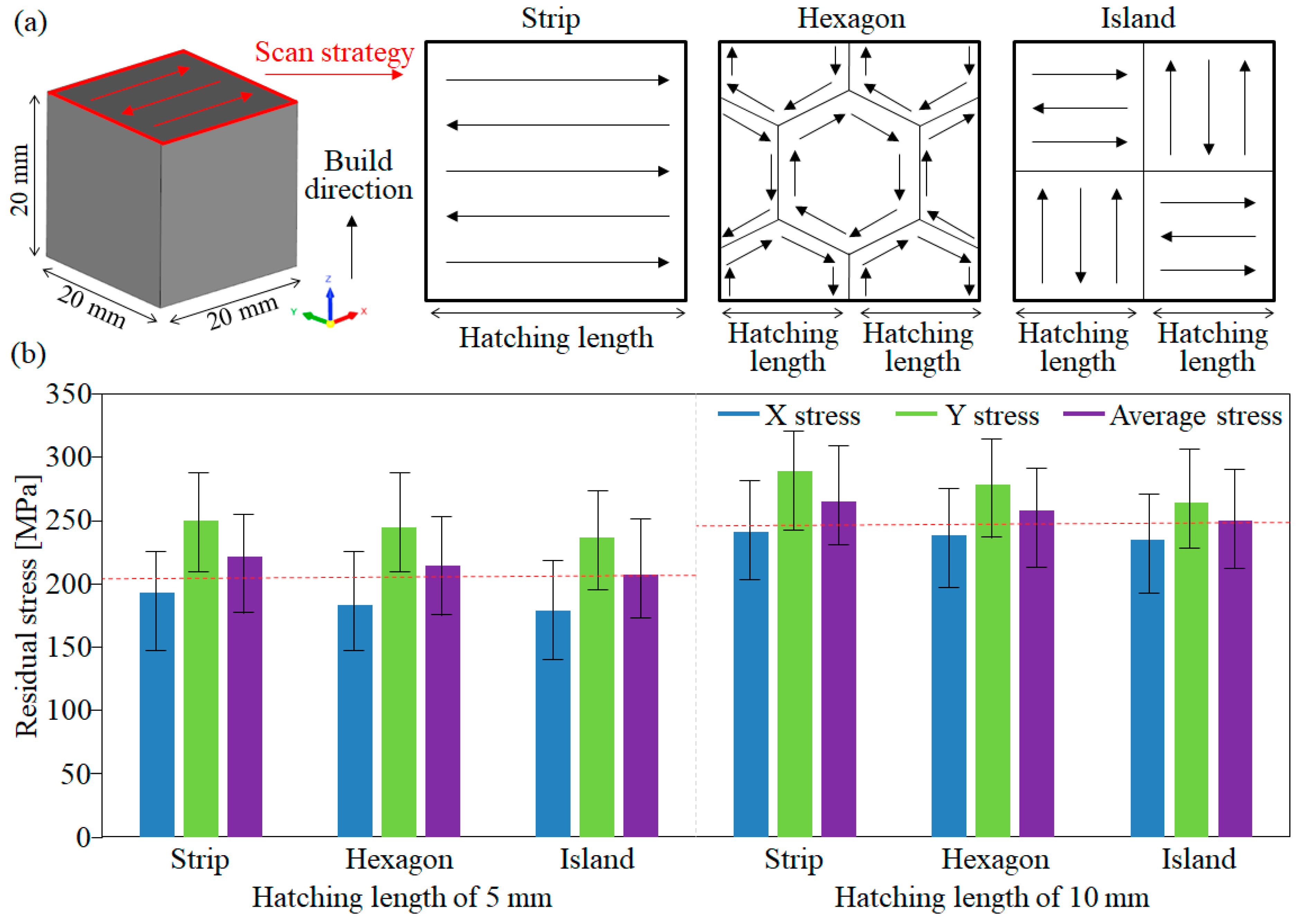
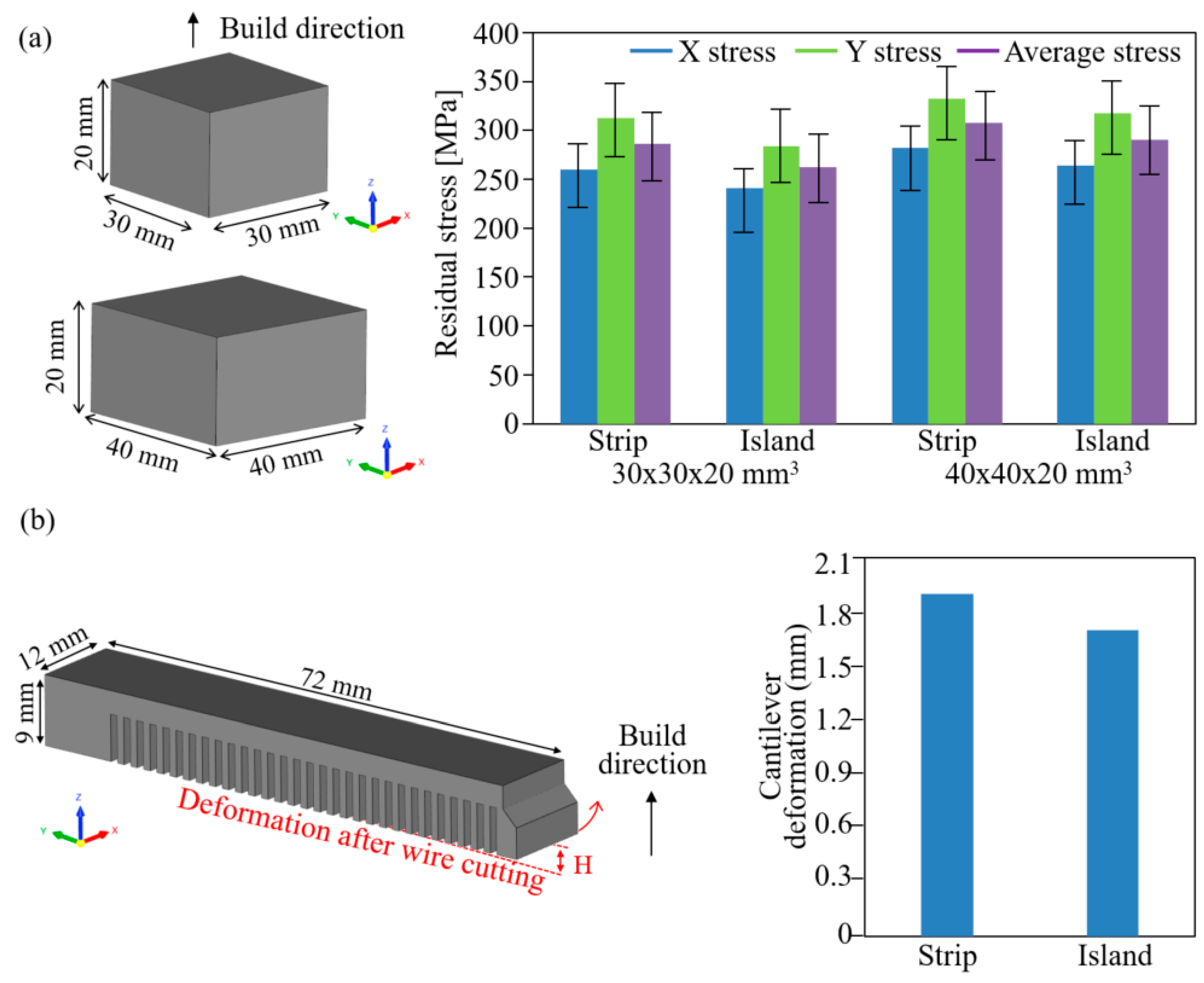
2.2. PBF Scan Strategy Method to Reduce Residual Stress

The topology optimization model has an irregularly shaped region, and different melting regions occur in each layer, which may lead to excessive thermal deformation depending on the residual stress characteristics. The effective laser scan strategy is required in the PBF process to reduce thermal residual stress. In this chapter, the residual stress of parts manufactured using the laser scanning process was analyzed using X-ray measurement (μ-X360 portable, Pulstec Industrial Co., Shizuoka, Japan). As shown in Figure 1, 20 × 20 × 20 mm3 specimens were fabricated with strip, hexagonal and island pattern (Figure 1a). The residual stress in a specimen deposited on the plate tends to increase with height, with the highest residual stress typically measured at the top surface if part cutting was not performed [30]. The hatching length of the scan strategy was compared at 5 and 10 mm and the residual stress was averaged by measuring 16 points on the top surface.
Given the residual stress along scan directions, measurements were taken in both the X and Y directions of the specimen and then the residual stresses in the two directions were averaged. As shown in Figure 1b, the X direction of residual stress of 192.8, 183.3, and 178.8 MPa, the Y direction of residual stress of 249.4, 244.2, and 236.1 MPa, and average residuals stress of 221.1, 213.8, and 207.4 MPa were measured for the strip, hexagon, and island patterns in the hatching length of 5 mm cubic specimens. In addition, the X direction of the residual stress of 241.1, 238.2, and 234.5 MPa and the Y direction of residual stress of 289.2, 277.9, and 264.1 MPa and average residuals stress of 265.1, 257.8, and 249.3 MPa were measured for the strip, hexagon, and island pattern in the hatching length of 10 mm cubic specimens. The error bars of residuals stress are caused by the difference in thermal stress values according to position. This is due to the localized heating that induces a rapidly thermal gradient along the laser track, generating thermal stress in the subsequent track and layer. In the case of the laser scan pattern, the boundaries of overlapping hatching lengths lead to local heat accumulation, which affects the size of the error bars. Consequently, residual stresses with deviations, as indicated by the error bars, arise at certain points. The residual stress values were averaged to effectively compare the differences in error values that occurred for each scan pattern. By averaging the measurements, the average residual stress of the island pattern was found to be lower than other scan strategies such as strip or hexagon patterns. The residual stress was lower at a 5 mm hatching length than at a 10 mm hatching length. In the case of strip and hexagon, the anisotropic residual stress was high because they had a scan pattern in only one direction pattern. Furthermore, as the hatching length increases, the resulting residual stress tends to be higher due to the increasing anisotropic property of the part.
Figure 2 shows the measurement of the residual stress and cantilever deformation to analyze the isotropic properties according to scan strategy. As shown in Figure 2, the residual stress and thermal deformation characteristics were analyzed using specimens with sizes of 30 × 30 × 20 and 40 × 40 × 20 mm3 and a cantilever with a size of 12 × 72 × 9 mm3.
The X direction of the residual stress of 260.1 and 241.2 MPa, and the Y direction of residual stress of 312.7 and 283.5 MPa, and average residuals stress of 286.4 and 262.3 MPa were measured for the strip and island pattern in 30 × 30 × 20 mm3 specimens. The X direction of residual stress of 282.2 and 263.8 MPa, and the Y direction of residual stress of 332.7 and 317.3 MPa, and average residuals stress of 307.4 and 290.6 MPa were measured for the strip and island pattern in 40 × 40 × 20 mm3 specimen (Figure 2a). After additive manufacturing the cantilever, the bottom surface was cut using wire cutting, and the height from the bottom surface was measured to compare the thermal deformation. The deformation of the cantilever when using the strip and island patterns was 1.92 and 1.76 mm, respectively (Figure 2b). As the area of the specimen increases, the cumulative heat capacity of the part increases and the residual stress increases. By applying the island pattern, the residual stress was reduced by 5.47–8.41% in 30 × 30 × 20 mm3 and 40 × 40 × 20 mm3 specimens. In addition, the island pattern can reduce the cantilever deformation by 8.33%, reducing the anisotropic property.

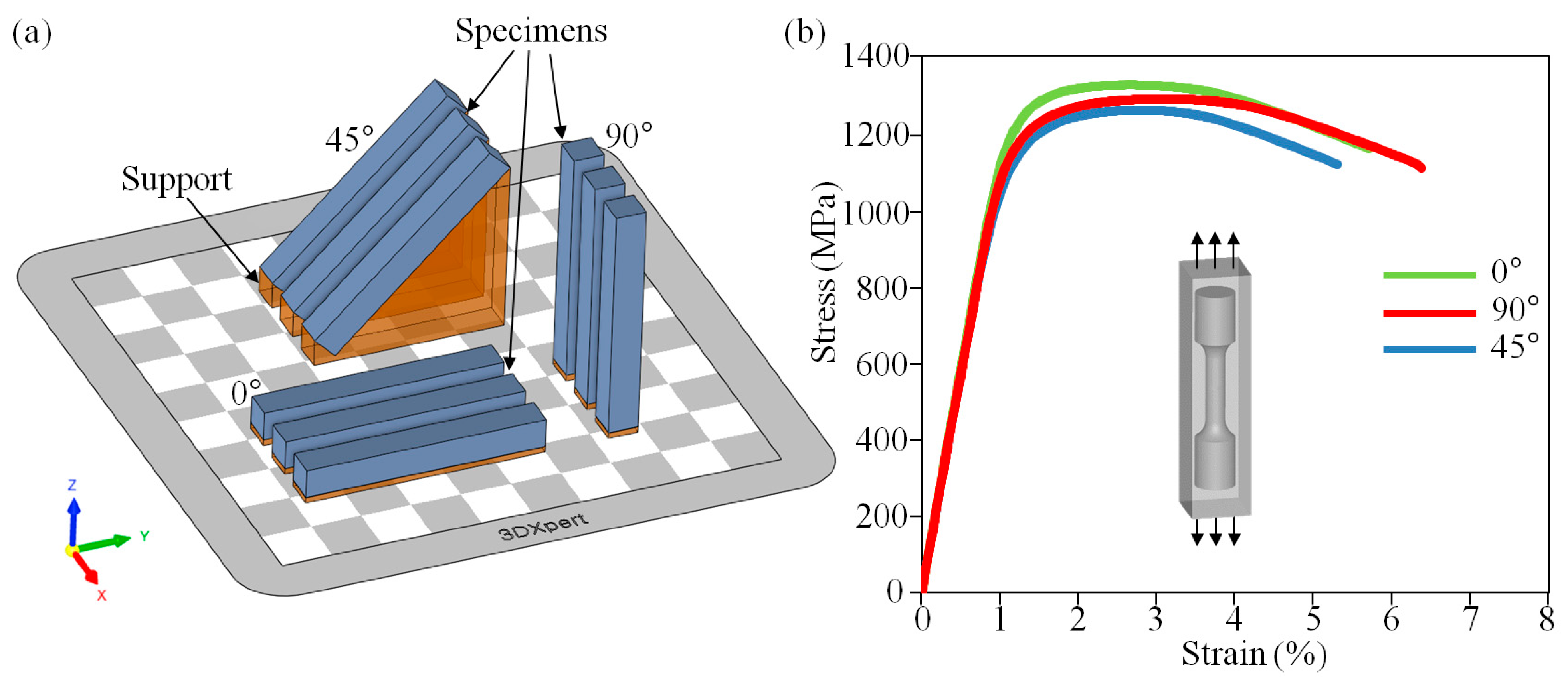
2.3. Mechanical Property According to Build Orientation

The mechanical strength produced varies based on the build direction, owing to the layer-by-layer additive manufacturing process. When additively manufacturing a product, it is necessary to select the build direction considering the mechanical properties. The effect of melting area and cooling rate, thus the effect of the microstructure of additively manufactured specimens, affect the strength and strain [31,32]. Usually, the fabricated Ti–6Al–4V specimens using the PBF process have high ultimate tensile strength and lower elongation due to rapid cooling rate compared to conventionally produced titanium alloy [32,33]. As a low elongation rate can lead to the formation of cracks or defects within components during the PBF process, it is imperative to enhance the elongation rate corresponding to the build orientation. As shown in Figure 3a, in order to determine the build direction of the model (horizontal (0°), diagonal (45°), and vertical (90°) orientation.), improving the machinability and structure property, as-built specimens were manufactured according to the build direction and evaluated using tensile tests. The manufactured specimen was machined based on the ASTM E8 standard (Standard Test Methods for Tension Testing of Metallic Materials [34]), and a tensile test was performed. As shown in Figure 3b and Table 1, the tensile strength and elongation measured from 1333 MPa and 5.8% in the horizontal direction structure, 1289 MPa and 5.4% in the diagonal direction structure, and 1307 MPa and 6.7% in the vertical direction specimens.
Based on these experiments, low-ductility tensile strength was highest in horizontal orientation and elongation was highest in vertical orientation. The PBF process in the vertical direction with high elongation can effectively reduce defects attributed to low heat accumulation of a small melting area and thermal deformation.

3. Additive Manufacturing Strategy of Brake Caliper Model

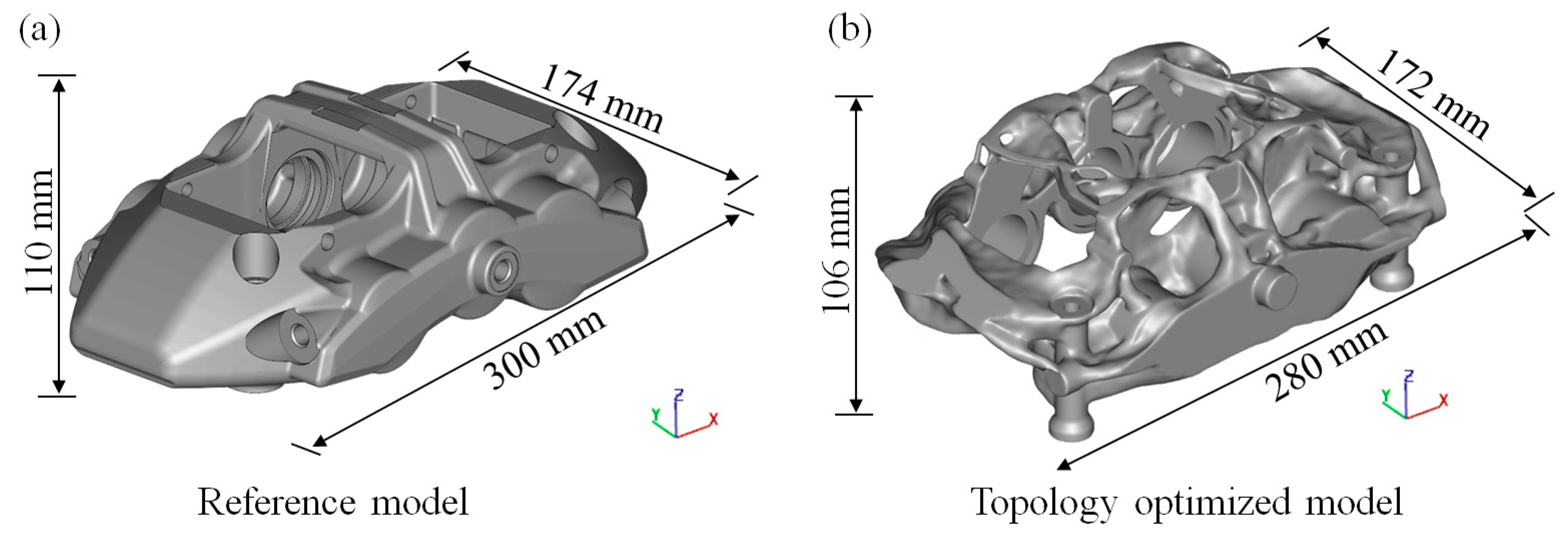
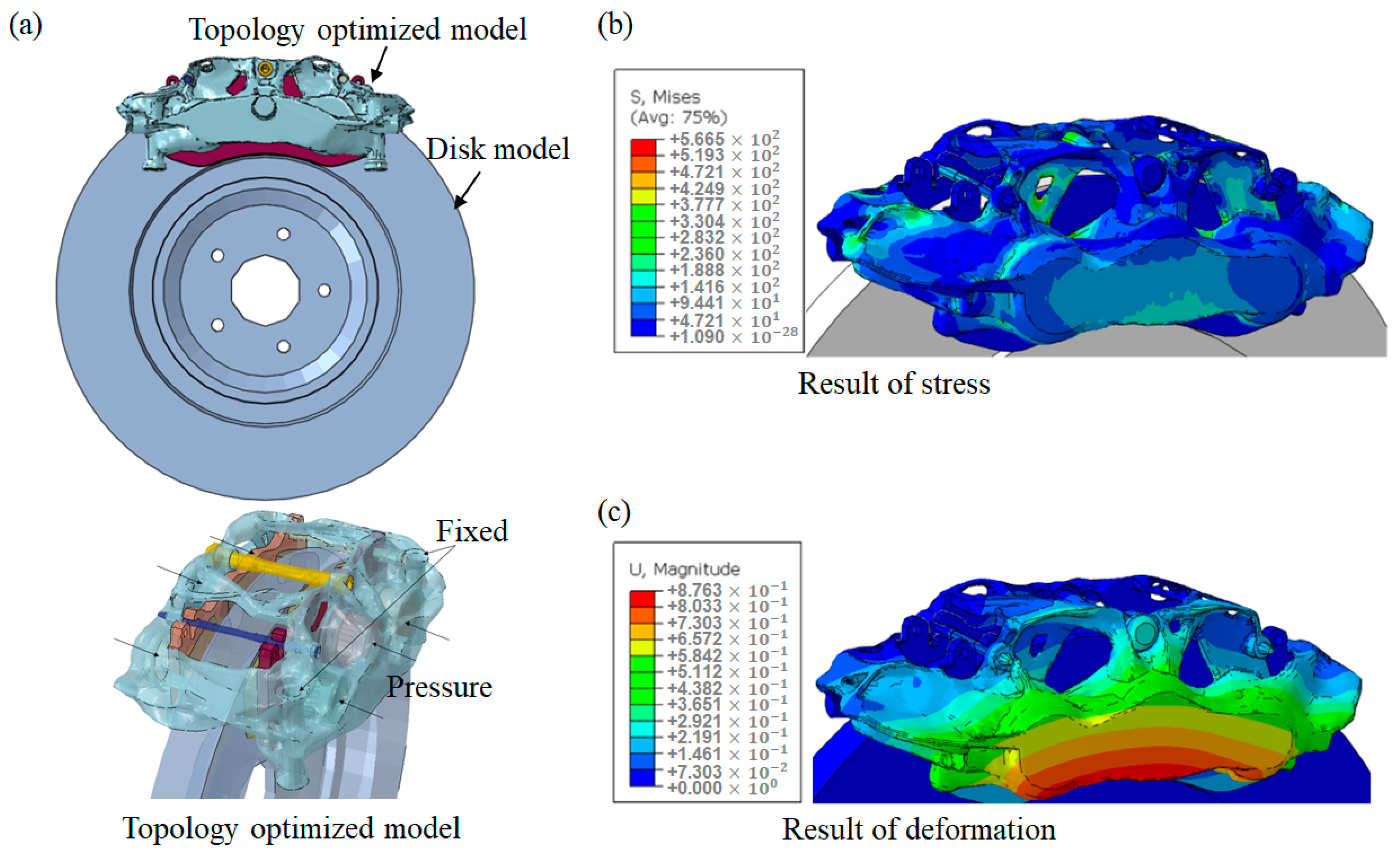
3.1. Topology Optimization of Brake Caliper Model

The weight of the brake caliper model was reduced via topology optimization to determine the full potential of AM. The topology optimization was performed according to the following processes. First, the design domain was constructed based on the dimensions from the reference design (size of 300 × 174 × 110 mm3, Woosin Industries Corporation, Gimhae-si, Republic of Korea) shown in Figure 4a. Oil channels and assembling holes were set as non-design areas, and unnecessary areas for machining and bolting were removed in advance. The main bridge of the reference design was replaced by bolting assemblies, and two side bridge areas were added to determine a new load path. Second, loading and boundary conditions were set for performance evaluation during the topology optimization. A hydraulic pressure of 13.7 MPa was applied to the inner wall of the oil channel of the non-design domain, and the jig-fixing regions of the two cylinder shapes were fixed, excluding the cylindrical rotation degree of freedom. Additionally, a force in the braking direction was applied to each center of the oil cylinder to consider the braking condition. Third, an optimization problem was formulated to minimize the weight while satisfying the deformation constraints of the reference design. The average deformation values of both inner and outer surfaces extending the oil cylinder centerlines were constrained for hydraulic pressure, and the average deformation values of both oil cylinder centers were constrained for the braking force. Finally, topology optimization design was performed with the solid isotropic material with penalization (SIMP) model using Altair OptiStruct [35] based on the material properties of Ti–6Al–4V. The strength was not directly constrained during topology optimization; however, the maximum stress was maintained within the allowable range because the deformation conditions were dominant.
The result obtained from topology optimization shown in Figure 4b and the model has a structural shape that cannot be made by conventional fabrication methods such as casting or milling. Despite using titanium material, which has a 38% higher density than aluminum, a weight reduction of 20% was obtained while satisfying both deformation and stress conditions.
The topology optimized design shown in Figure 4b was smoothed using the OSSmooth function and exported to Altair Inspire for further modification. The PolyNURBS function in Inspire was used to modify the shape comprehensively. Extremely thin branch structures were removed or thickened, and the jig-fixing area was reinforced. Small holes were filled in to improve the AM quality but were eventually removed via the machining process.
The topology optimization method significantly impacts weight reduction in parts, but it can create a weak area due to thinning in unexpected places. To prevent this weak point, verification through FEM analysis is required. FEM was performed on the brake caliper components to evaluate the mechanical properties of the topology-optimized model using ABAQUS software (V6.5.1, Dassault Systemes, Vélizy-Villacoublay, France) [36]. The 3D CAD data, mesh type, complexity, mesh optimization, analysis reliability, and contact between caliper components were considered when constructing the FEM models. The FEM analysis of the topology-optimized model is shown in Figure 5. The boundary conditions were defined as shown in Figure 5a. The bolting position was fixed, and pistons in the caliper were applied at 13.7 MPa, which is the pressure level for the leaking test of the caliper. The contact between the pad faces and disc, as well as the contact between the plate of the outboard pad and caliper, were defined as surface-to-surface contact with friction-tangential behavior. The properties of Ti–6Al–4V material were applied to the topology optimization of the brake caliper model.
The stress and deformation results of the brake calipers generated in the brake system are shown in Figure 5b,c, respectively. Regarding the topology optimization of the brake caliper, when a hydraulic pressure of 13.7 MPa was applied, the maximum stress was 566.5 MPa, which was 54.9% of the yield strength, and the maximum deformation was 0.88 mm in the end of caliper. As a result of FEM analysis, the yield strength of the brake system was lower than the yield strength of Ti–6Al–4V material, and the maximum stress generated was half of the yield strength. In addition, the topology model fabricated using titanium alloy has a higher mechanical strength than the existing caliper fabricated using aluminum alloy owing to its material characteristics; additionally, it is advantageous in terms of safety [37].

3.2. Design and Additive Manufacturing of Brake Caliper

The thermal conduction Ti–6Al–4V is lower than that of conventional materials. Therefore, Ti-6Al-4V material exhibits low heat dissipation, leading to heat accumulation, thermal deformation, and residual stress in the PBF process. To prevent excessive thermal deformation, the melt area must be divided and patterned through the PBF process strategy to reduce residual stress [38]. As shown in Figure 6, residual stress and melting area were analyzed according to the vertical and horizontal brake caliper model to reduce the thermal deformation of the PBF part. To analyze deformation caused by thermal stress during PBF, the thermal stress and deformation based on the building direction was compared via numerical analysis of the Amphyon in 3Dxpert software (V24.1.1, 3D Systems, Rock Hill, SC, USA) [39]. The material’s mechanical properties and material characteristics suited to laser scanning were considered when constructing the thermal deformation simulation. As shown in Figure 6a, in order to analyze the thermal deformation of only additively manufactured part, the no-support design was generated, and the numerical analysis was performed. As a result of numerical analysis, the maximum thermal stress and deformation were 1124, 1034 MPa, and 13.7, 7.8 mm in the horizontal and vertical directions, respectively. As shown in Figure 6b, the vertical and horizontal melting areas are uneven, and in the case of the horizontal direction, the melting area per layer is higher. Despite the additional 33.5 h required for manufacture, the thermal stress and deformation in the vertical direction were 5.9 mm, 43.1% less than in the horizontal direction, due to the difference in the melting area of orientation.
In the previous contents, the PBF process of reducing anisotropic residual stress and thermal deformation was analyzed. For high-quality manufacturing of additive manufacturing parts, a topology optimization brake caliper was manufactured by applying an island pattern with a hatching length of 5 mm and vertical orientation of the model. As shown in Figure 7a, the support design was carried out. To prevent excessive thermal deformation, the parts where thermal deformation is high in the analysis were designed with cone supports to prevent thermal deformation. As shown in Figure 7b,c, the topology optimization of the brake caliper was manufactured and the supports, which were manufactured alongside the brake caliper, have been processed, and the additively manufactured part has been finalized (part mass of 2.59 kg).
During the AM of large components, such as brake calipers, heat accumulation occurs owing to the large area involved, which causes thermal deformation [38,40]. Therefore, the manufactured caliper must be scanned and then compared with a CAD file to verify the dimensional error of the product. As shown in Figure 8, the error rate was analyzed by overlapping the two models based on the origin coordinates of the model scanned with the brake caliper using t Surveyor ZS-3040 (Laser Design Inc., Golden Valley, MN, USA) scanning equipment and CAD data for topology optimization. As a result of comparing the topology optimization model and scan data (additive manufacturing part), the maximum error rate was 97 μm and the topological brake caliper of the precise shape was manufactured using the effective PBF process.

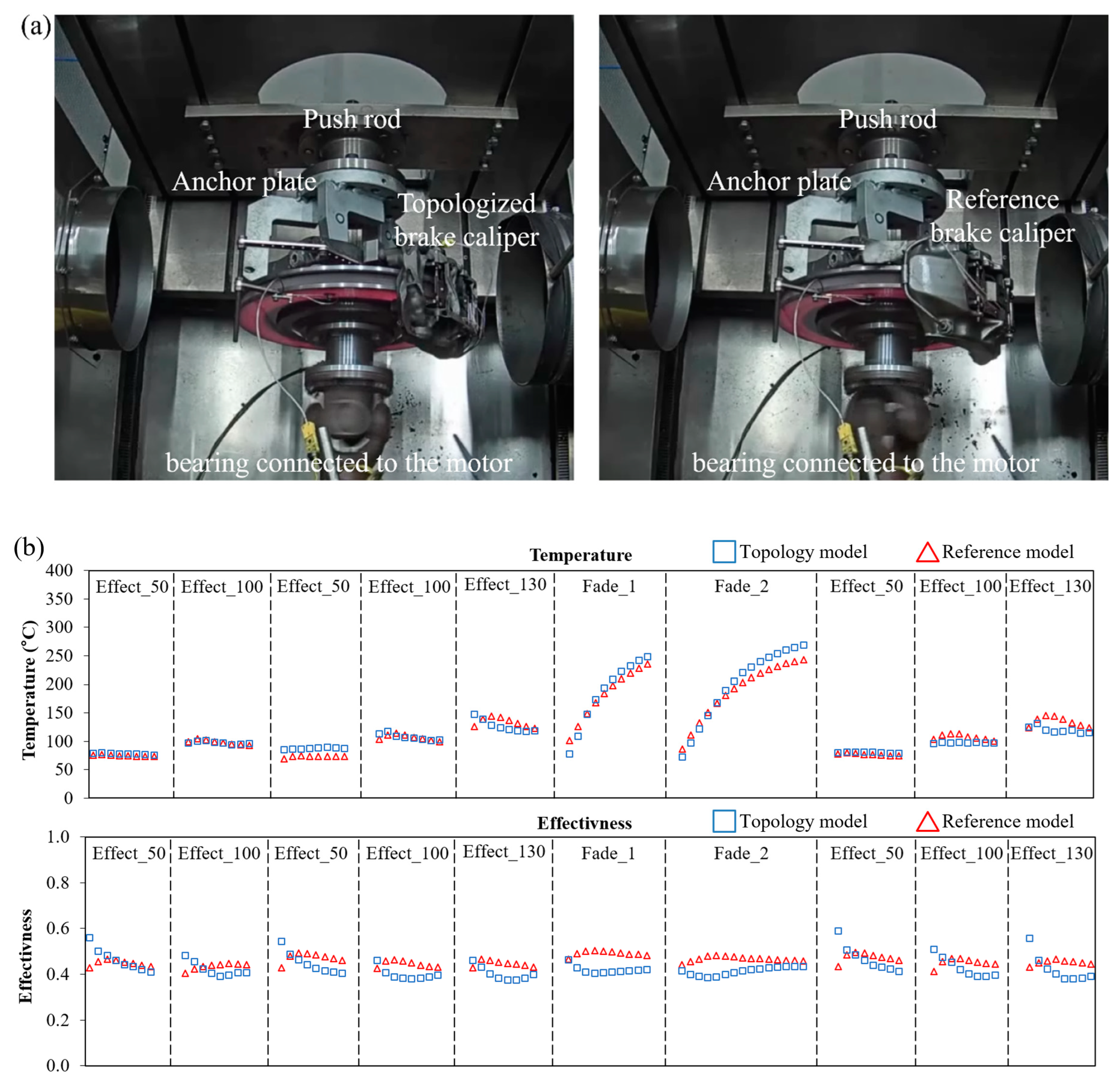
3.3. Evaluation of Topology Optimized Brake Caliper

The performance of the topology-optimized brake caliper was evaluated based on comparison with the commercial product. As shown in Figure 9a, the topology-optimized brake caliper and the reference brake caliper were mounted on the disc. The test procedure of the brake caliper was evaluated based on the JASO C406 (Japanese Automobile Standards Organization C406) test procedure using a brake dynamometer [41]. The sequence of the JASO C406 test procedure is as follows: burnish, first effectiveness, first reburnish, first fade, recovery, second reburnish, second fade, and recovery. The effectiveness test was performed at three different braking speeds (50, 80, and 100 km/h) and eight different decelerations (0.1–0.8 g). The fade and recovery steps were a series of tests for evaluating the effects of brake systems changed by continuous braking. In the first step of fade and recovery, 0.3 g deceleration was performed 10 times for 35 s at 100 km/h, and the same conditions were repeated 15 times in the second step of fade and recovery. As shown in Figure 9b, the temperature, frictional force effectiveness, and pressure were analyzed via brake dynamometer experiments of the topology-optimized and reference models.
In terms of temperature, both models showed values within 15 °C. However, a temperature gradient appeared because the thermal conductivity of titanium is lower than that of aluminum, therefore, heat accumulation occurred in the fade experiment. In terms of the frictional force effectiveness, the friction effect of topology-optimized model was as high as 0.01~0.03 in the initial brake dynamometer of each step. However, continuous experimentation with a topological brake caliper can result in performance degradation due to heat accumulation in the Ti-6Al-4V material, attributed to its low thermal conductivity. Nevertheless, it maintains frictional performance similar to that of the commercial product. Based on the results of JASO C 406, the performance of the additively manufactured brake caliper using the effective PBF process is comparable to that that of the commercial product.

4. Summary and Conclusions

The topology optimization brake caliper model with lightweight and high-strength characteristics is precisely manufactured. Based on the numerical analysis and the experimental results of topological model, the following conclusions can be inferred:
  • The residual stress was reduced by 5.47–8.41% and the thermal deformation of the cantilever by 8.33% compared to the strip process by applying an island pattern with a hatching length of 5 mm.
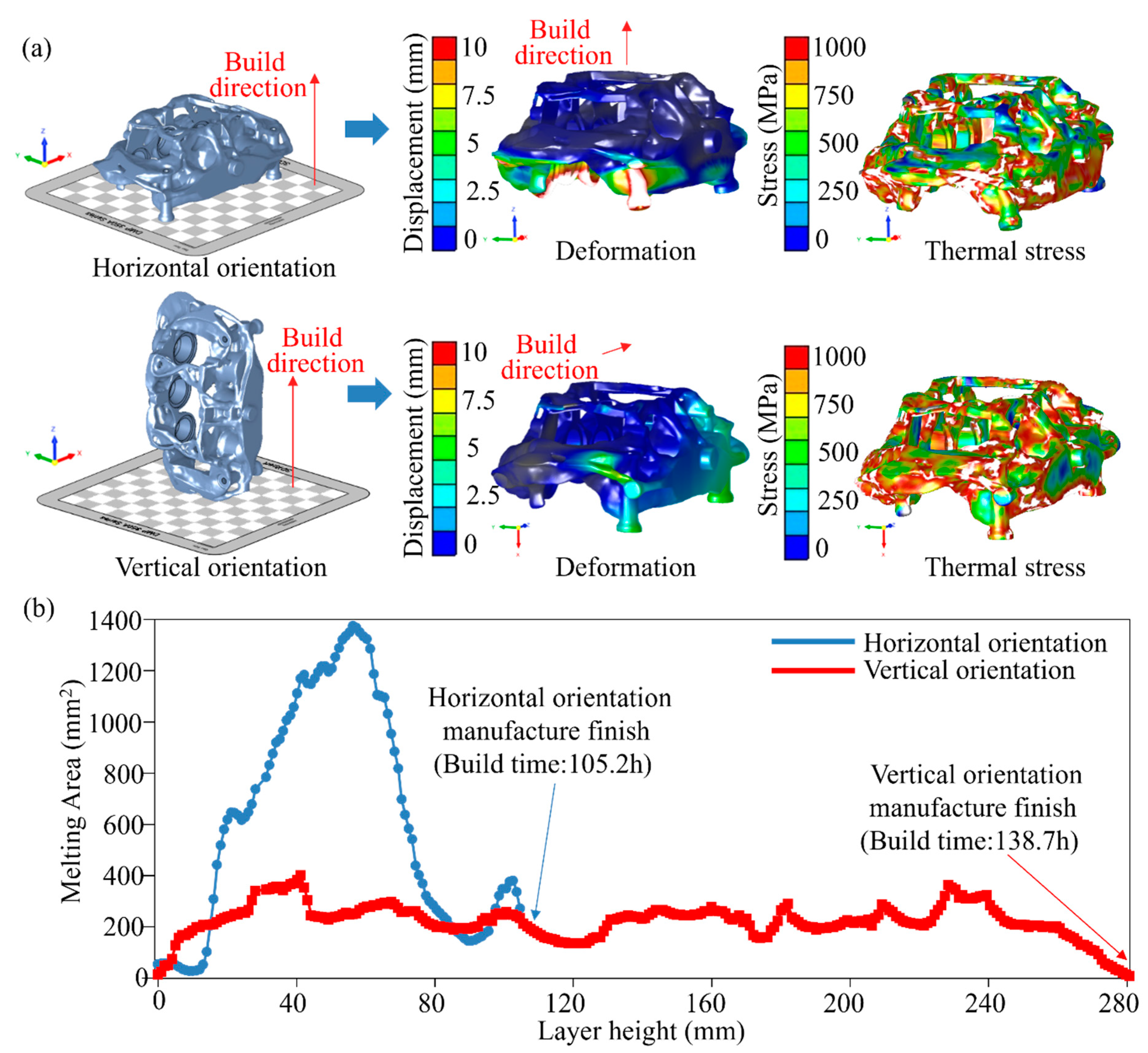
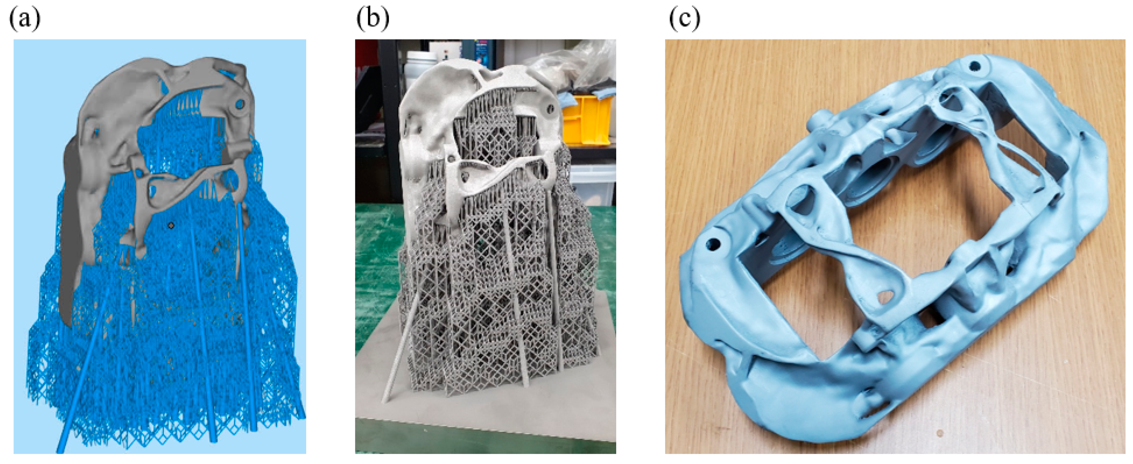
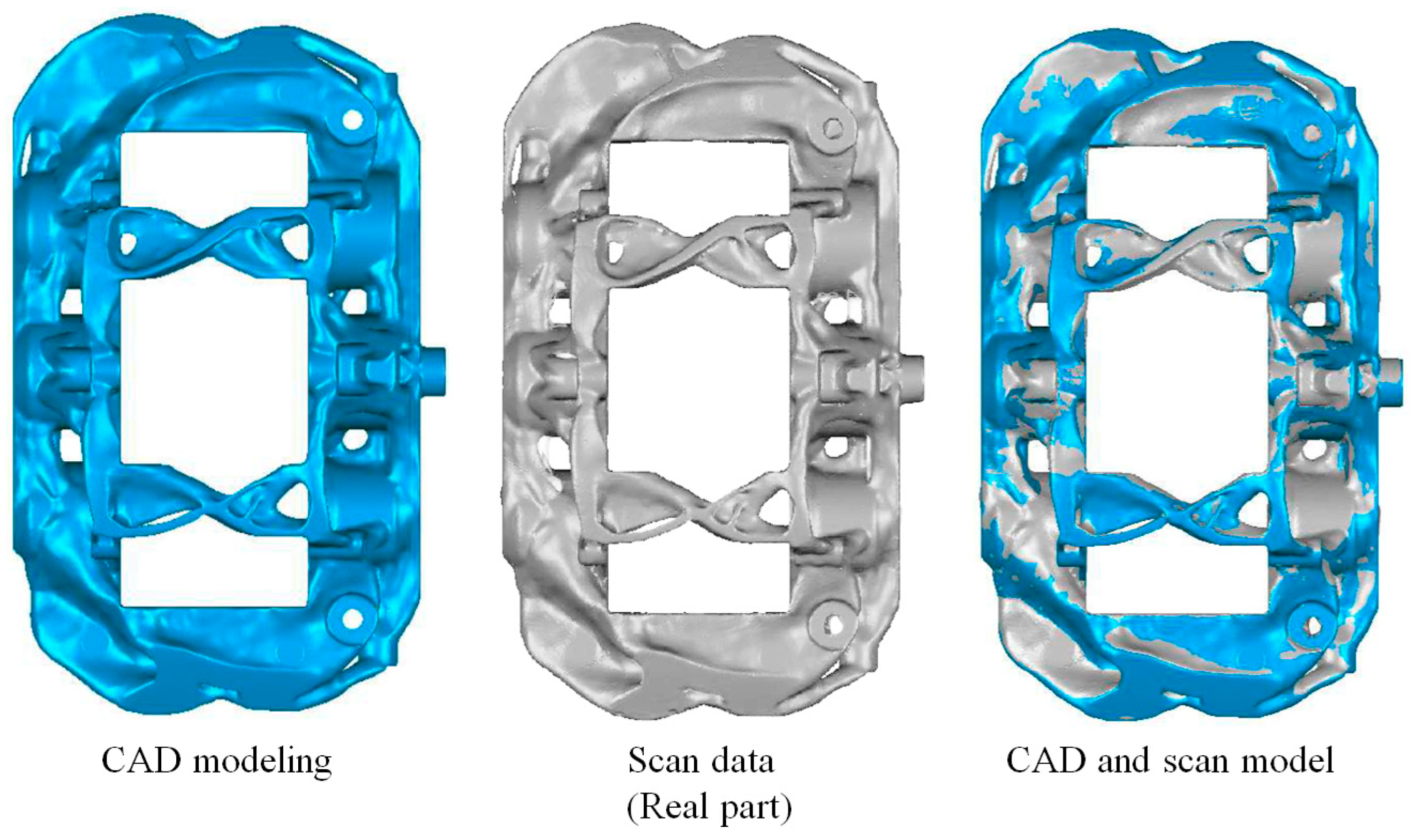
  • The topology-optimized brake caliper is built with a vertical orientation that minimizes the melting area that causes thermal deformation and residual stress. With an effective PBF process, a topology model and a precise brake caliper with an error of up to 97 μm were fabricated.
  • The brake performance of the topology-optimized brake caliper was evaluated based on JASO C406. The brake performance of the topology-optimized model equals or surpasses that of the commercial product.
As a result of this study, it is possible that additive manufacturing parts applicable to the automotive industry can be manufactured through an effective PBF process. In addition, through a new topology-optimized brake caliper, fuel efficiency can be improved and showed the possibility of using it as a commercial automobile brake system.

Author Contributions

J.Y.: conceptualization, methodology, visualization, experiments, investigation, formal analysis, software, writing—original draft, review and editing. Y.J.: conceptualization, methodology, visualization, experiments, investigation, formal analysis, software, writing—original draft, review and editing. J.J.: visualization, experiments, formal analysis, investigation. J.D.O.: experiments, formal analysis, investigation. S.C.: methodology, investigation, formal analysis. S.H.P.: methodology, investigation, formal analysis. T.H.L.: conceptualization, supervision, funding acquisition, project administration, writing—original draft, review and editing. J.P.: conceptualization, supervision, funding acquisition, project administration, writing—original draft, review and editing. All authors have read and agreed to the published version of the manuscript.

Funding

This study was supported by the Technology Innovation Program funded by the Ministry of Trade, Industry & Energy (MOTIE) of Korea (1415175160), and the Korea Institute of Industrial Technology (KITECH) internal project (JE240029) and by the Incheon Metropolitan City (UR240077/IZ240077).

Data Availability Statement

The original contributions presented in the study are included in the article, further inquiries can be directed to the corresponding authors.

Conflicts of Interest

Authors Youngsuk Jung and Shinhu Cho were employed by Hyundai Motor Group. Author Jae Dong Ock was employed by Woosin Industries Corporation. The remaining authors declare that the research was conducted in the absence of any commercial or financial relationships that could be construed as a potential conflict of interest.

References

  1. Bartlett, J.L.; Li, X. An overview of residual stresses in metal powder bed fusion. Addit. Manuf. 2019, 27, 131–149. [Google Scholar] [CrossRef]
  2. Seifi, M.; Salem, A.; Beuth, J.; Harrysson, O.; Lewandowski, J.J. Overview of materials qualification needs for metal additive manufacturing. JOM 2016, 68, 747–764. [Google Scholar] [CrossRef]
  3. Murr, L.E.; Gaytan, S.M.; Ramirez, D.A.; Martinez, E.; Hernandez, J.; Amato, K.N.; Wicker, R.B. Metal fabrication by additive manufacturing using laser and electron beam melting technologies. J. Mater. Sci. Technol. 2012, 28, 1–14. [Google Scholar] [CrossRef]
  4. Liu, R.; Wang, Z.; Sparks, T.; Liou, F.; Newkirk, J. Aerospace applications of laser additive manufacturing. In Laser Additive Manufacturing; Woodhead Publishing: Cambridge, UK, 2017; pp. 351–371. [Google Scholar]
  5. Juechter, V.; Franke, M.M.; Merenda, T.; Stich, A.; Körner, C.; Singer, R.F. Additive manufacturing of Ti-45Al-4Nb-C by selective electron beam melting for automotive applications. Addit. Manuf. 2018, 22, 118–126. [Google Scholar] [CrossRef]
  6. Li, J.; Hu, J.; Zhu, Y.; Yu, X.; Yu, M.; Yang, H. Surface roughness control of root analogue dental implants fabricated using selective laser melting. Addit. Manuf. 2020, 34, 101283. [Google Scholar] [CrossRef]
  7. Harzheim, L.; Graf, G.; Klug, S.; Liebers, J. Topologieoptimierung im praktischen Einsatz. ATZ-Automob. Z. 1999, 101, 530–539. [Google Scholar] [CrossRef]
  8. Kranz, J. Methodik und Richtlinien für Die Konstruktion von Laseradditiv Gefertigten Leichtbaustrukturen; Springer: Berlin/Heidelberg, Germany, 2017. [Google Scholar]
  9. Dagkolu, A.; Gokdag, I.; Yilmaz, O. Design and additive manufacturing of a fatigue-critical aerospace part using topology optimization and L-PBF process. Procedia Manuf. 2021, 54, 238–243. [Google Scholar] [CrossRef]
  10. Yıldız, A.R.; Kılıçarpa, U.A.; Demirci, E.; Doğan, M. Topography and topology optimization of diesel engine components for light-weight design in the automotive industry. Mater. Test. 2019, 61, 27–34. [Google Scholar] [CrossRef]
  11. Bendsoe, M.P.; Sigmund, O. Topology Optimization: Theory, Methods, and Applications; Springer Science & Business Media: Berlin/Heidelberg, Germany, 2003. [Google Scholar]
  12. Großmann, A.; Weis, P.; Clemen, C.; Mittelstedt, C. Optimization and re-design of a metallic riveting tool for additive manufacturing—A case study. Addit. Manuf. 2020, 31, 100892. [Google Scholar] [CrossRef]
  13. Kumaran, M.; Senthilkumar, V. Generative design and topology optimization of analysis and repair work of industrial robot arm manufactured using additive manufacturing technology. IOP Conf. Ser. Mater. Sci. Eng. 2021, 1012, 012036. [Google Scholar] [CrossRef]
  14. Mantovani, S.; Barbieri, S.G.; Giacopini, M.; Croce, A.; Sola, A.; Bassoli, E. Synergy between topology optimization and additive manufacturing in the automotive field. Proc. Inst. Mech. Eng. Part B J. Eng. Manuf. 2021, 235, 555–567. [Google Scholar] [CrossRef]
  15. Chen, X.; Yin, J.; Wang, W.; Wu, L.; Tang, F. Approaches to diminish large unsprung mass negative effects of wheel side drive electric vehicles. J. Adv. Mech. Des. Syst. Manuf. 2016, 10, JAMDSM0064. [Google Scholar] [CrossRef]
  16. Kandukuri, S.Y.; Pai, A.; Manikandan, M. Scope of Carbon Fibre-Reinforced Polymer Wheel Rims for Formula Student Racecars: A Finite Element Analytical approach. J. Inst. Eng. (India) Ser. C 2022, 103, 939–948. [Google Scholar] [CrossRef]
  17. Natarajan, H.K. Study of silicon carbide-reinforced aluminum matrix composite brake rotor for motorcycle application. Int. J. Adv. Manuf. Technol. 2018, 94, 1461–1475. [Google Scholar]
  18. Jamal, M.H.M.; Saleh, M.K.M. Design and Analysis an Efficient Lightweight Brake Caliper for Kuim Electric Vehicle. J. Eng. Health Sci. 2019, 2, 67–78. [Google Scholar]
  19. Maijer, D.M.; Gao, Y.X.; Lee, P.D.; Lindley, T.C.; Fukui, T. A through-process model of an A356 brake caliper for fatigue life prediction. Metall. Mater. Trans. A 2004, 35, 3275–3288. [Google Scholar] [CrossRef]
  20. Merulla, A.; Gatto, A.; Bassoli, E.; Munteanu, S.I.; Gheorghiu, B.; Pop, M.A.; Munteanu, D. Weight reduction by topology optimization of an engine subframe mount, designed for additive manufacturing production. Mater. Today Proc. 2019, 19, 1014–1018. [Google Scholar] [CrossRef]
  21. Sanaei, N.; Fatemi, A.; Phan, N. Defect characteristics and analysis of their variability in metal L-PBF additive manufacturing. Mater. Des. 2019, 182, 108091. [Google Scholar] [CrossRef]
  22. Roehling, J.D.; Smith, W.L.; Roehling, T.T.; Vrancken, B.; Guss, G.M.; McKeown, J.T.; Matthews, M.J. Reducing residual stress by selective large-area diode surface heating during laser powder bed fusion additive manufacturing. Addit. Manuf. 2019, 28, 228–235. [Google Scholar] [CrossRef]
  23. Wang, Y.; Guo, W.; Xie, Y.; Li, H.; Zeng, C.; Xu, M.; Zhang, H. In-situ monitoring plume, spattering behavior and revealing their relationship with melt flow in laser powder bed fusion of nickel-based superalloy. J. Mater. Sci. Technol. 2024, 177, 44–58. [Google Scholar] [CrossRef]
  24. Guo, Q.; Zhao, C.; Qu, M.; Xiong, L.; Hojjatzadeh, S.M.H.; Escano, L.I.; Parab, N.D.; Fezzaa, K.; Sun, T.; Chen, L. In-situ full-field mapping of melt flow dynamics in laser metal additive manufacturing. Addit. Manuf. 2020, 31, 100939. [Google Scholar] [CrossRef]
  25. Srivastava, S.; Garg, R.K.; Sharma, V.S.; Alba-Baena, N.G.; Sachdeva, A.; Chand, R.; Singh, S. Multi-physics continuum modelling approaches for metal powder additive manufacturing: A review. Rapid Prototyp. J. 2020, 26, 737–764. [Google Scholar] [CrossRef]
  26. Bian, P.; Shi, J.; Liu, Y.; Xie, Y. Influence of laser power and scanning strategy on residual stress distribution in additively manufactured 316L steel. Opt. Laser Technol. 2020, 132, 106477. [Google Scholar] [CrossRef]
  27. Nadammal, N.; Mishurova, T.; Fritsch, T.; Serrano-Munoz, I.; Kromm, A.; Haberland, C.; Bruno, G. Critical role of scan strategies on the development of microstructure, texture, and residual stresses during laser powder bed fusion additive manufacturing. Addit. Manuf. 2021, 38, 101792. [Google Scholar] [CrossRef]
  28. Liu, J.; Li, G.; Sun, Q.; Li, H.; Sun, J.; Wang, X. Understanding the effect of scanning strategies on the microstructure and crystallographic texture of Ti-6Al-4V alloy manufactured by laser powder bed fusion. J. Mater. Process. Technol. 2022, 299, 117366. [Google Scholar] [CrossRef]
  29. Thompson, S.M.; Bian, L.; Shamsaei, N.; Yadollahi, A. An overview of Direct Laser Deposition for additive manufacturing; Part I: Transport phenomena, modeling and diagnostics. Addit. Manuf. 2015, 8, 36–62. [Google Scholar] [CrossRef]
  30. Zhang, H.; Li, C.; Xu, M.; Dai, W.; Kumar, P.; Liu, Z.; Li, Z.; Zhang, Y. The fatigue performance evaluation of additively manufactured 304L austenitic stainless steels. Mater. Sci. Eng. A 2021, 802, 140640. [Google Scholar] [CrossRef]
  31. Liu, S.; Shin, Y.C. Additive manufacturing of Ti6Al4V alloy: A review. Mater. Des. 2019, 164, 107552. [Google Scholar] [CrossRef]
  32. Ganeriwala, R.K.; Strantza, M.; King, W.E.; Clausen, B.; Phan, T.Q.; Levine, L.E.; Hodge, N.E. Evaluation of a thermomechanical model for prediction of residual stress during laser powder bed fusion of Ti-6Al-4V. Addit. Manuf. 2019, 27, 489–502. [Google Scholar] [CrossRef]
  33. Nguyen, H.D.; Pramanik, A.; Basak, A.K.; Dong, Y.; Prakash, C.; Debnath, S.; Buddhi, D. A critical review on additive manufacturing of Ti-6Al-4V alloy: Microstructure and mechanical properties. J. Mater. Res. Technol. 2022, 18, 4641–4661. [Google Scholar] [CrossRef]
  34. Kardak, A.A.; Sinclair, G.B. Stress concentration factors for ASTM E8/E8M-16a standard round specimens for tension testing. J. Test. Eval. 2020, 48, 711–719. [Google Scholar] [CrossRef]
  35. Altair OptiStruct 2016: Users Guide; Altair Engineering, Inc.: Troy, MI, USA, 2016.
  36. ABAQUS/Standard User’s Manual for Version 6.5.1; Hibbitt, Karlsson and Sorensen Inc.: Pawtucket, RI, USA, 2004.
  37. Yang, Y.; Li, M.; Li, K.R. Comparison and analysis of main effect elements of machining distortion for aluminum alloy and titanium alloy aircraft monolithic component. Int. J. Adv. Manuf. Technol. 2014, 70, 1803–1811. [Google Scholar] [CrossRef]
  38. Mugwagwa, L.; Yadroitsava, I.; Makoana, N.W.; Yadroitsev, I. Residual stress in laser powder bed fusion. In Fundamentals of Laser Powder Bed Fusion of Metals; Elsevier: Amsterdam, The Netherlands, 2021; pp. 245–276. [Google Scholar]
  39. 3Dsystems 3Dxpert. User’s Manual. Available online: https://www.3dsystems.com/software/3dxpert (accessed on 5 November 2024).
  40. Li, C.; Liu, Z.Y.; Fang, X.Y.; Guo, Y.B. Residual stress in metal additive manufacturing. Procedia Cirp 2018, 71, 348–353. [Google Scholar] [CrossRef]
  41. Aranganathan, N.; Mahale, V.; Bijwe, J. Effects of aramid fiber concentration on the friction and wear characteristics of non-asbestos organic friction composites using standardized braking tests. Wear 2016, 354, 69–77. [Google Scholar] [CrossRef]
Figure 1. Measurement of residual stress, (a) laser scan strategies; and (b) measurement of residual stress according to scan pattern and hatching length.
Metals 14 01277 g001
Figure 2. Measurement of residual stress and thermal deformation, (a) image of specimen model and measurement of residual stress; and (b) image of specimen model and thermal deformation of cantilever.
Metals 14 01277 g002
Figure 3. Stress–strain graph and tensile specimens along different directions. (a) direction of manufactured specimens; and (b) stress–strain curve.
Metals 14 01277 g003
Figure 4. Brake caliper model; (a) reference model; and (b) topology-optimized model.
Metals 14 01277 g004
Figure 5. Boundary conditions and results of FEM analysis. (a) Topology-optimized model and boundary conditions; (b) result of stress; and (c) result of deformation.
Metals 14 01277 g005
Figure 6. Considerations for AM orientation (a) thermal deformation of horizontal and vertical orientation (b) melting area on build direction according to orientation.
Metals 14 01277 g006
Figure 7. Additive manufacturing process of topology-optimized brake caliper. (a) Support design; (b) additively manufactured brake caliper; and (c) removing the support.
Metals 14 01277 g007
Figure 8. Evaluation of dimensional error via CAD modeling and scan data comparison.
Metals 14 01277 g008
Figure 9. Dynamometer experiments (JASO C406), (a) topology-optimized brake caliper and commercial product (casting product); and (b) test results of dynamometer test.
Metals 14 01277 g009
Table 1. Result of tensile experiment according to building direction.
ParametersTensile Stress (MPa)Elongation (%)
Horizontal orientation1333 ± 235.8 ± 0.3
Diagonal orientation1289 ± 275.4 ± 0.4
Vertical orientation 1307 ± 306.7 ± 0.4
Disclaimer/Publisher’s Note: The statements, opinions and data contained in all publications are solely those of the individual author(s) and contributor(s) and not of MDPI and/or the editor(s). MDPI and/or the editor(s) disclaim responsibility for any injury to people or property resulting from any ideas, methods, instructions or products referred to in the content.

