
Advancements in Laser Powder Bed Fusion of Carbon Nanotubes-Reinforced AlSi10Mg Alloy: A Comprehensive Analysis of Microstructure Evolution, Properties, and Future Prospects

 ,
,  ,
,  ,
,  ,
, 

Abstract
:1. Introduction
1.1. AlSi10Mg Alloy: Composition, Characteristics, and Phase Constituents
1.2. Enhancing Performance through Composite Reinforcements
1.3. L-PBF: Advantages and Applications for AlSi10Mg Alloy Processing
- The high silicon content in the AlSi10Mg alloy’s chemical composition enhances its fluidity by promoting efficient heat dissipation during solidification. This improved fluidity reduces the likelihood of microcrack formation and facilitates the healing of any existing cracks [35].
- AlSi10Mg alloy exhibits low dimensional shrinkage and limited residual stress, thereby reducing its susceptibility to cracking during the solidification process. This characteristic is beneficial for achieving successful fabrication through L-PBF, as it minimizes the occurrence of detrimental cracks [83].
- The solidification range of AlSi10Mg alloy is significantly narrower compared to higher-strength aluminum alloys like the 7000 series. This narrower solidification range makes AlSi10Mg more amenable to the L-PBF process [84]. Additionally, L-PBF technology can accommodate high-temperature heat treatment cycles for the metallic powder feedstocks, further expanding its suitability for fabricating this alloy.
- L-PBF provides exceptional precision in fabricating complex shapes and geometries, which is crucial for producing components with intricate designs and features. This aspect is particularly significant for the AlSi10Mg alloy, commonly employed in the aerospace industry, where tight tolerances and intricate parts are required [14,85,86].
1.4. Evolution of Microstructure in L-PBF-Fabricated AlSi10Mg-Based Parts
2. AlSi10Mg Alloy: Comparing L-PBF with Traditional Fabrication Technologies
3. L-PBF-Printed CNT-Reinforced AlSi10Mg Composites
3.1. Process Variables
3.1.1. Impact of CNTs on Scanning Track Morphology
3.1.2. Impact of Scan Speed on the Distribution of CNTs
3.1.3. Optimizing Laser Energy Density for Densification of CNT-Reinforced AlSi10Mg
3.1.4. Influence of CNTs on Surface Quality
3.2. Microstructure
3.2.1. Powder Feedstock Preparation
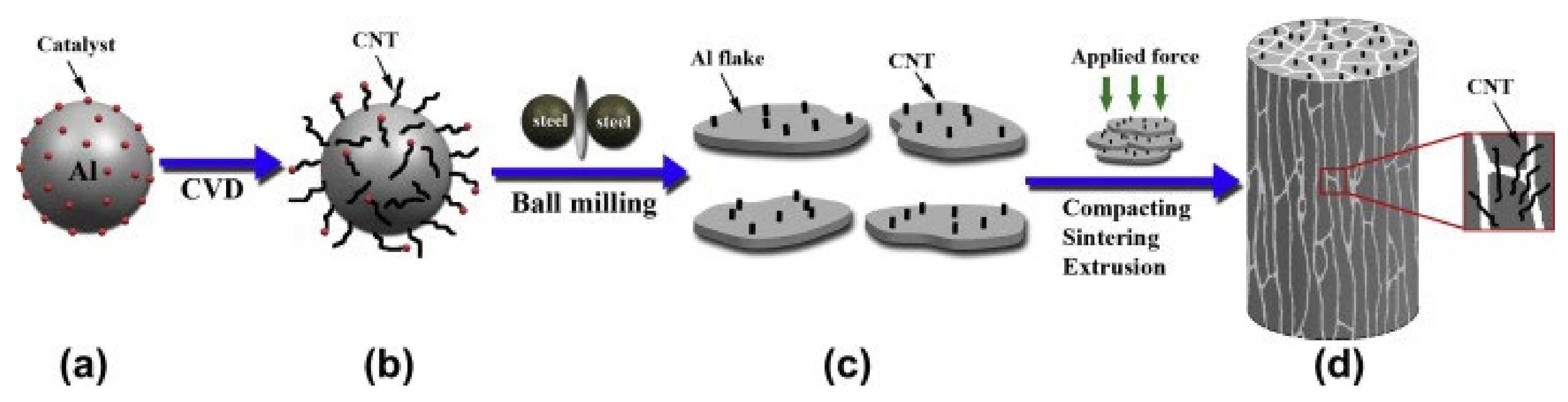
- Ball milling is a widely utilized technique for processing composite powder feedstocks in L-PBF manufacturing. It involves the application of high-energy mechanical force to combine nanoparticles with metal powder. This process is typically conducted at room temperature and incorporates a process control agent (PCA). The principal mechanism involved is the repetitive deformation and welding of powder particles through collisions with the grinding balls, resulting in the formation of a fine-grained composite powder. By adjusting the grinding parameters, the processed blend can be optimized. However, this technique has a notable drawback: the resulting composite particles tend to experience undesirable superficial oxidation and exhibit reduced fluidity, leading to a loss of sphericity. These characteristics significantly impact the formability and densification behavior of printed products [152,153];
- Gas or plasma atomization is another technique used for the processing of composite powder feedstocks. In this method, the spherical composite powder is generated by a powder atomizer through the combination of reinforced particles with a molten aluminum alloy. This process yields highly uniform spherical composite powder with excellent flowability. However, it is important to note that this technique is relatively time-consuming and costly [154];
- Electrostatic self-assembly is another approach utilized for the blending of composite powders. It involves the even mixing of two dissimilar powders, where one powder carries a positive surface charge and the other powder carries a negative charge. The electrostatic attraction between the particles enables their uniform distribution. While this technique effectively addresses the limitations associated with ball milling, it is a complex process with limited performance. Moreover, it often leads to poor binding between the particles, as achieving consistent electrical charging can be challenging [155].
3.2.2. Densification Behavior
3.2.3. Dominant Mechanisms in Microstructure Evolution
- In many cases, it is challenging to directly observe CNTs in the microstructure of L-PBF-processed samples. However, the presence of elemental carbon, which confirms the existence of CNTs, can be detected through elemental analysis. The elemental carbon is uniformly distributed within the AlSi10Mg matrix [82]. This suggests that CNTs may undergo partial or complete degradation during high-energy laser irradiation. The observed reduction in CNT length compared to the primary nanotubes and the significant decrease in their volume percentage indicate changes that occur during the L-PBF process [82,158];
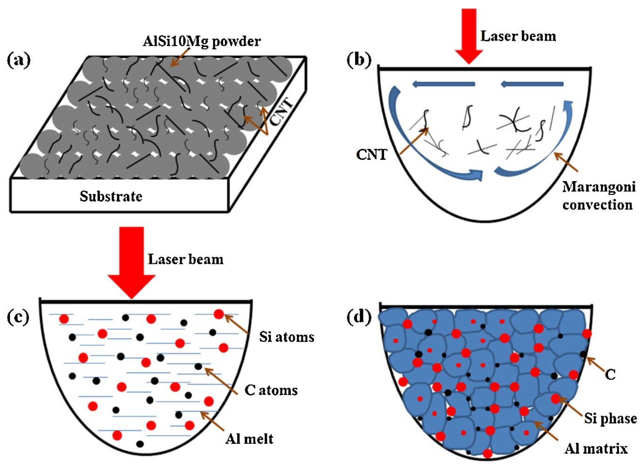
- Prior to L-PBF, during the ball milling stage, the entangled CNTs become attached to the surfaces of AlSi10Mg particles while maintaining their tubular morphology. However, when exposed to high-energy laser irradiation, the thermal stability of CNTs is compromised due to defects induced by ball milling. This leads to their thermal decomposition into elemental carbon, which then diffuses within the melt pool as a result of Marangoni flow-induced melt vibration. The elemental carbon undergoes a chemical reaction with the Al matrix, leading to the in-situ formation of Al4C3. Consequently, the outer layer of the CNTs in contact with the Al matrix consists of Al4C3 [134,159];
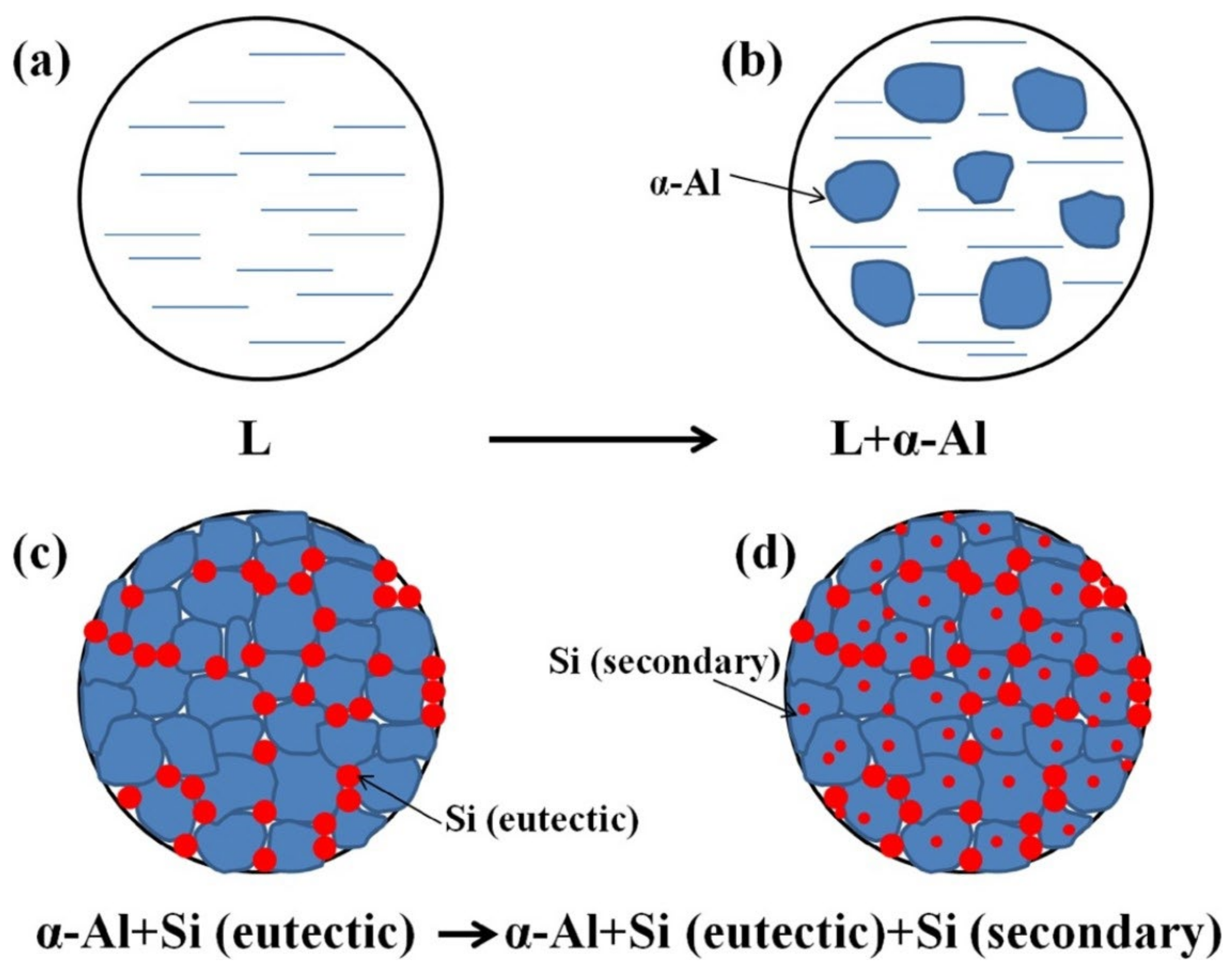
- During the L-PBF process, a distinctive microstructure develops in CNT-reinforced AlSi10Mg matrix nanocomposites. This microstructure consists of solidified α-Al grains arranged in a cellular morphology, accompanied by a discontinuous network of the silicon phase. The size of the Al cells increases with higher CNT content [160]. Figure 8 depicts the scanning electron microscopy (SEM) image of L-PBF-printed CNT-reinforced AlSi10Mg matrix nanocomposites, clearly identifying both phases, namely eutectic silicon and cellular aluminum [159,161]. The proposed mechanism for the microstructure evolution in these composites is as follows: (i) Initially, the α-Al phase undergoes solidification, leaving residual silicon at the grain boundaries [120]. (ii) Subsequently, the silicon forms a supersaturated Al-Si solid solution, leading to the segregation of coarse elemental silicon particles and Si-Al eutectic sheets at the primary Al grain boundaries. The resulting microstructure, as depicted in Figure 8, exhibits brighter zones corresponding to the eutectic silicon phase segregated from the AlSi10Mg matrix, while darker regions represent the α-Al phase. It is notable that the aluminum regions are surrounded by silicon particles, maintaining their cellular equiaxed grain structure [75];
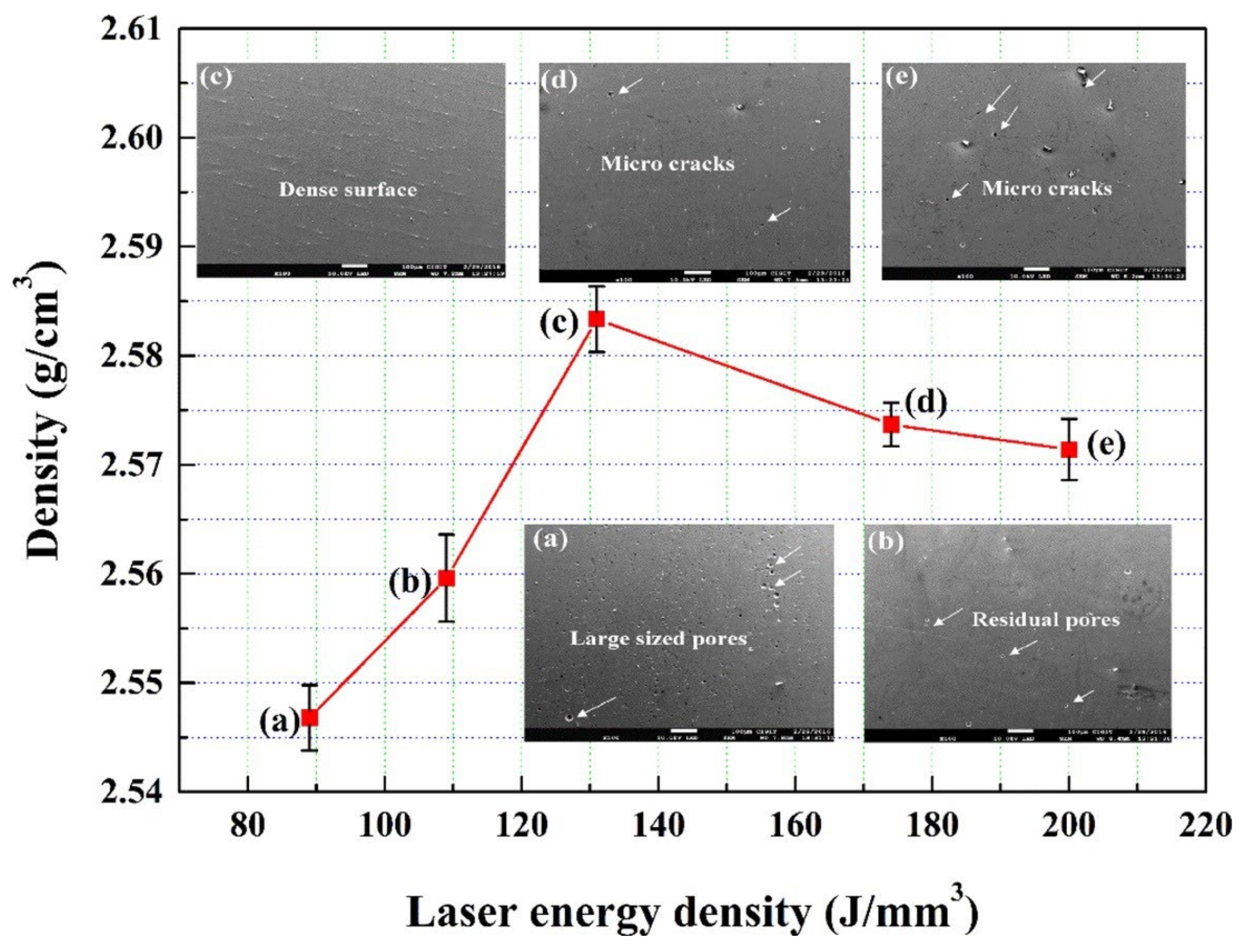
- Elemental silicon is predominantly concentrated along the grain boundaries of the Al grains. It is deposited in the form of thin eutectic sheets with nanoscale thickness along these boundaries. The precipitation of eutectic silicon becomes more challenging with higher cooling rates employed during L-PBF, resulting in smaller generated precipitates. In other words, a higher LED corresponds to a greater likelihood of silicon particle formation in L-PBF [82];
- Increasing the laser power or LED can promote the growth of primary α-Al grains [82].
3.2.4. Potential Phase Transformations
- CNTs exhibit superior thermal conductivity and possess a large specific surface area, enabling them to efficiently absorb laser energy during the L-PBF process. As a consequence, the CNTs undergo thermal decomposition, leading to either the formation of elemental carbon or their evaporation. The extent of this decomposition is influenced by the laser energy density (LED) applied during L-PBF. Elevated LED values enhance the effectiveness of Marangoni flow, a phenomenon associated with vibrational motion within the melt pool. This intensified fluid dynamics promotes the diffusion of atomic carbon within the molten material, consequently increasing the likelihood of nucleation events for the formation of Al4C3 precipitates;
- AlSi10Mg is prone to chemical interaction with oxygen impurities, leading to the formation of an oxide film on the surface of the melt pool during the L-PBF process. Consequently, the presence of this oxide film can give rise to the occurrence of small Al2O3 precipitates within the aluminum matrix, attributable to the oxidation of the molten material. These precipitates have been found to contribute to the formation of elongated microcracks that propagate toward the surface of the printed component;
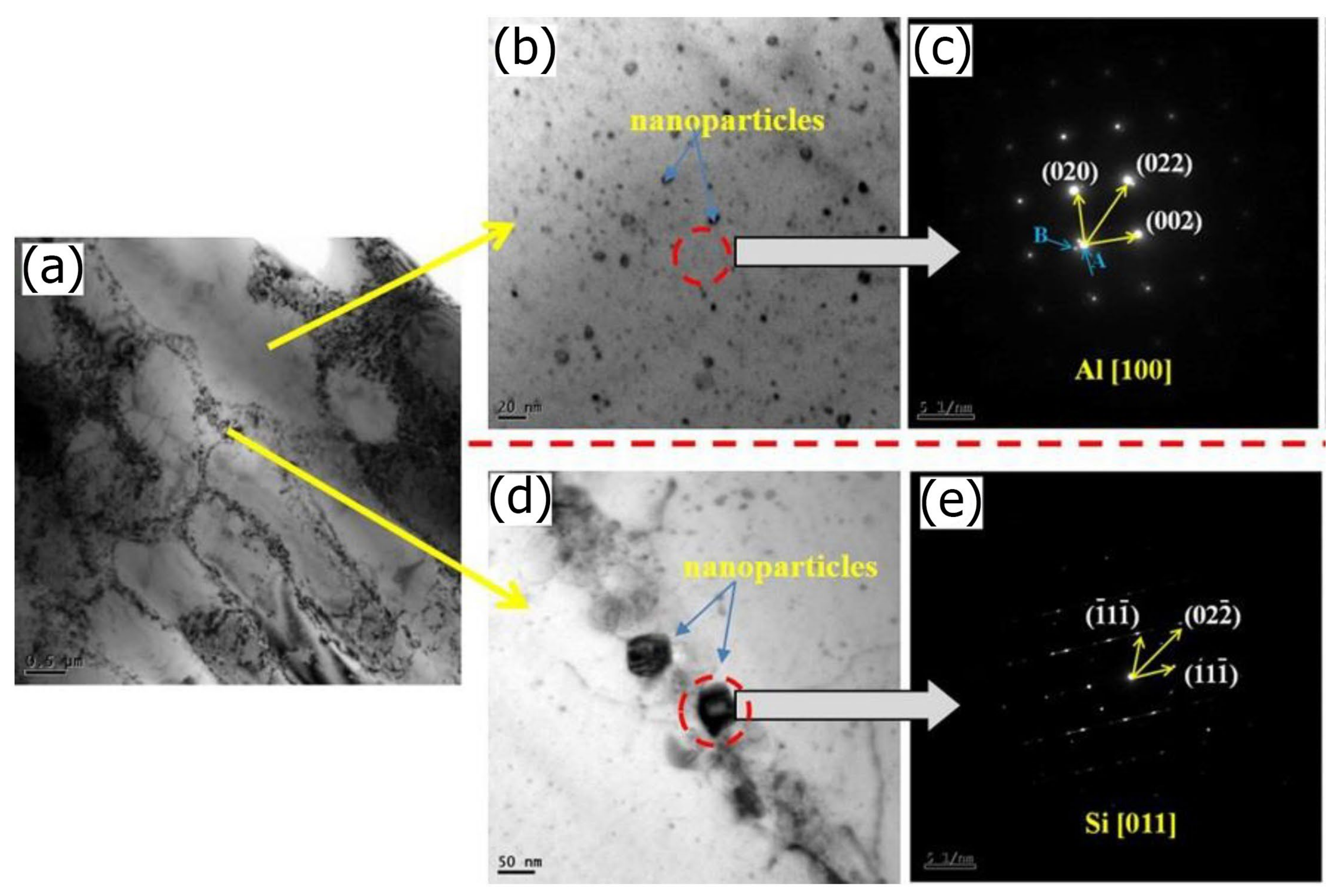
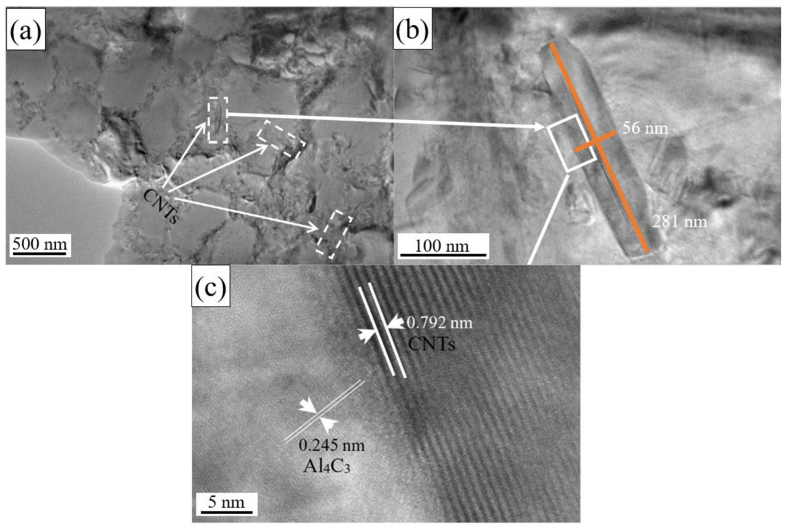
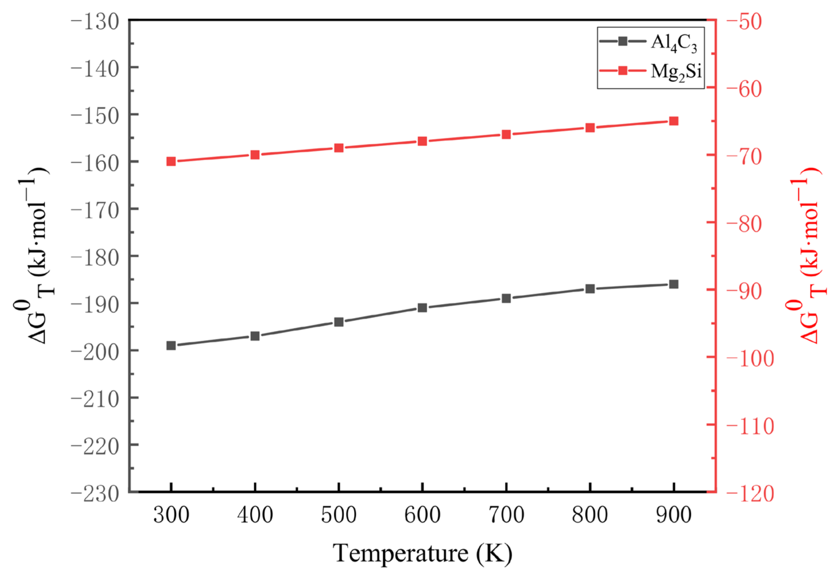
- Under sufficiently low cooling rates, the formation of Mg2Si and Al4C3 phases can occur in the AlSi10Mg alloy. The presence of Mg2Si arises from the silicon element’s supersaturation within the AlSi10Mg matrix, while the formation of Al4C3 is a result of a chemical reaction between the decomposed CNTs and the aluminum matrix. It is expected that Al4C3 will predominantly develop on the outer surface of CNTs, specifically at the interface between the nanotubes and the metallic matrix. This phenomenon is depicted in Figure 9, where CNTs are encapsulated by a thin layer of the Al4C3 phase. From a thermodynamic standpoint, the Al4C3 phase can exist within the temperature range of 600 to 1000 °C; however, if the temperature exceeds 1400 °C, it will decompose into elemental aluminum and carbon. Additionally, it should be noted that higher cooling rates in the melt pools, such as those on the order of 104–105 K/s, can diminish the likelihood of Al4C3 formation;
- Although some researchers have hypothesized the presence of the Al9Si phase resulting from the supersaturation of the Al-Si solid solution and the segregation of silicon in the aluminum matrix, no empirical evidence confirming its existence has been reported to date. This is likely due to the low concentrations of Al9Si in the parts produced by L-PBF. Further investigations are required to validate the presence of the Al9Si phase and elucidate its formation mechanism in L-PBF-printed components.
3.2.5. Development of Defects
- The presence of gases in the vicinity of the melt pool, which can dissolve into the solidifying metal;
- Agglomeration of CNTs and entrapment of gases between the particles;
- Superficial adsorption of gases on the high-specific-area CNTs during consolidation and L-PBF;
- Incomplete filling of gaps during the rapid solidification process;
3.2.6. Effect of CNTs on Grain Structure
4. Physico-Mechanical Properties
4.1. Hardness
- In the presence of CNTs, a chemical reaction occurs with the alloy matrix, resulting in the formation of a thin film of in-situ Al4C3 interfacial phase on the outer surfaces of the nanotubes. This thermodynamically stable film plays a crucial role in enhancing load transfer and improving the microhardness of the composite. However, it should be noted that, if the processing conditions, particularly the energy inputs, are set too high, CNTs may undergo thermal decomposition, leading to a decrease in microhardness [82,159];
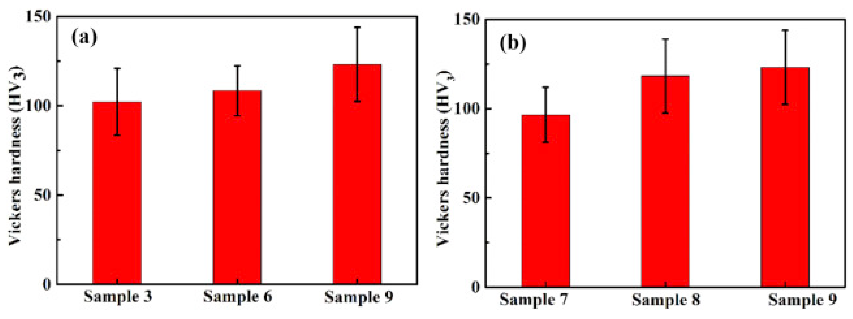
- With an increase in laser energy density (e.g., from 89 to 131 J/mm3), the microhardness of the material initially improves (e.g., from 115 HV to 145 HV), but then starts to decrease (e.g., 130 HV). The initial improvement can be attributed to the grain refinement effect caused by the presence of nanotubes, which suppresses grain coarsening during the L-PBF process. However, the subsequent decrease in microhardness can be attributed to the change in microstructural features, specifically the transition from equiaxed to columnar grain orientation, which promotes grain growth and reduces the overall hardness of the material [75,169];
- The addition of CNTs to the pristine alloy matrix leads to improved microhardness by inhibiting the atomic diffusion of alloying elements and the subsequent grain coarsening process. Additionally, during the L-PBF process, there is an ample opportunity for the formation of silicon (Si) precipitates, which is facilitated by the L-PBF technique. This results in the presence of cellular equiaxed α-Al and nanometric fibrous eutectic Si in the aluminum (Al) matrix. The Si can exist in the Al matrix as a solid solution, contributing to solid solution strengthening. Therefore, the combined effects of grain refinement strengthening and solid solution strengthening can be considered as two possible mechanisms that enhance the microhardness of CNT-reinforced AlSi10Mg composites [159];
- The increase in laser energy input up to an optimized level can enhance the hardness of the material by promoting the formation of finer silicon (Si) blocky particles within the aluminum (Al) matrix. This is accompanied by the activation of the Orowan strengthening mechanism, which involves the hindrance of dislocation motion by the presence of these particles. Furthermore, the rapid melting and solidification process induced by the high energy input can generate internal stresses, contributing to increased hardness. However, if the energy input exceeds the optimal range, deviations from the desired microhardness can occur. This can be attributed to the formation of microstructural defects, degradation of CNTs, or dissolution of hardening precipitates in the material. These factors can lead to a reduction in the hardness of the composite [82,162,170].
4.2. Tensile Strength
CNT Strengthening Mechanisms
4.3. Coefficient of Thermal Expansion
4.4. Electrical Resistivity
4.5. Wear
5. Challenges and Research Opportunities for CNT-AlSi10Mg Composites
- Dispersion and Alignment: Attaining a homogeneous dispersion and preferentially aligned distribution of CNTs within the AlSi10Mg matrix holds paramount importance in achieving exceptional properties. Challenges arise due to the inherent tendency of CNTs to agglomerate, which leads to inadequate dispersion and inefficiency in load transfer. Overcoming this challenge necessitates the development of effective dispersion techniques and strategies to ensure a uniform distribution throughout the matrix. This issue becomes more complex when employing L-PBF as the densification technique, as the sphericity of the powder feedstock assumes significant importance in this method. Any deficiency in this geometric characteristic can result in the formation of porosity and degradation of mechanical properties;
- Interfacial Bonding: The presence of weak interfacial bonding between CNTs and the AlSi10Mg matrix hampers efficient load transfer between the reinforcement and the matrix, thereby compromising the overall mechanical performance. Enhancing the interfacial bonding is crucial to maximize the potential benefits of CNTs in AlSi10Mg composites. Strategies such as surface functionalization and interfacial engineering can be explored to improve interfacial interactions.
- Thermal Stability: The L-PBF process entails high-temperature conditions that have the potential to degrade CNTs, thereby impacting their structural integrity and properties. Preserving the thermal stability of nanotubes during the L-PBF process is crucial to retain their advantageous characteristics. Novel approaches, including the application of protective coatings or the use of hybrid reinforcement systems, can be investigated to enhance the thermal stability of CNTs.
- Porosity and Defect Control: The authors propose the development of techniques aimed at minimizing porosity and defects in nanocomposites consisting of CNTs and an AlSi10Mg matrix densified via L-PBF. This can be achieved through the optimization of process parameters, manipulation of powder feedstock characteristics, or the implementation of post-processing treatments. By carefully fine-tuning process parameters and optimizing the properties of the powder feedstock, researchers can effectively reduce the occurrence of porosity and defects within the fabricated nanocomposites. Furthermore, the application of appropriate post-processing treatments can further enhance the overall mechanical properties of the materials. Through these advancements, the quality and performance of L-PBF-densified CNT-AlSi10Mg nanocomposites can be significantly improved.
- Multi-Scale Modeling: The authors propose the utilization of advanced modeling techniques, such as finite element analysis (FEA) or molecular dynamics (MD) simulations, to acquire a comprehensive understanding of the interactions occurring between CNTs and the AlSi10Mg matrix within nanocomposites. By employing these sophisticated computational tools, researchers can gain valuable insights into the mechanical behavior, stress transfer mechanisms, and failure modes occurring at different length scales. This enhanced understanding enables more precise design and optimization of CNT-reinforced AlSi10Mg composites. Through the application of FEA or MD simulations, researchers can evaluate and predict the performance of these nanocomposites, providing valuable guidance for future design and development efforts.
- Property–Performance Relationships: The authors propose an investigation into the correlation between the microstructure, processing parameters, and resulting properties of nanocomposites composed of CNTs and an AlSi10Mg matrix. This endeavor entails employing comprehensive characterization techniques, including mechanical testing, microstructural analysis, and measurements of electrical and thermal conductivity. By utilizing these techniques, researchers can establish clear relationships between the material composition, processing conditions, and the desired performance attributes. Through systematic analysis, it becomes possible to gain valuable insights into the influence of microstructural features and processing parameters on the mechanical, electrical, and thermal properties of CNT-AlSi10Mg nanocomposites. This knowledge is instrumental in guiding future material design and processing optimizations for enhanced performance.
6. Conclusions
- By exercising meticulous control over laser power, scanning speed, and layer thickness during the L-PBF process, the microstructure of CNT-AlSi10Mg nanocomposites can be finely tuned. The addition of CNTs to the AlSi10Mg matrix brings about notable enhancements in various properties, including wear resistance, electrical and thermal conductivity, tensile strength, thermal expansion characteristics, and hardness. The incorporation of CNTs imparts reinforcing effects, thereby yielding superior mechanical performance when compared to the pure AlSi10Mg alloy.
- In light of recent research endeavors, a conspicuous dearth of data emerges concerning several critical aspects within the realm of CNT-reinforced AlSi10Mg nanocomposites. These encompass the establishment of an optimal CNT content necessary for the formation of an appropriate percolation network within the aluminum matrix, the quantitative evaluation of CNT agglomeration tendencies, the induction of residual stress within the matrix as a consequence of CNT integration, the potential necessity for supplementary heat treatments, and the possible occurrence of undesirable chemical reactions between CNTs and the metallic matrix leading to the consequential diminishment of physico-mechanical properties. These parameters and practical variables offer promising avenues for future research initiatives, warranting focused attention to unravel their intricacies and implications.
- The impact of processing parameters on both the microstructure and properties of CNT-AlSi10Mg nanocomposites was subjected to comprehensive investigation. The findings highlight the pivotal role of optimized processing conditions, particularly laser power and scanning speed, in attaining favorable microstructural characteristics and mechanical properties. Precise adjustment of these parameters enables control over grain size, porosity, and the distribution of CNTs, thereby exerting a significant influence on the overall performance of the nanocomposites.
- Significant attention is directed towards the characterization of physico-mechanical properties, encompassing wear resistance, electrical and thermal conductivities, tensile strength, thermal expansion, and hardness. These properties hold paramount importance across diverse applications such as aerospace, automotive, and electronics industries, where the demand for lightweight materials exhibiting exceptional mechanical and functional characteristics is particularly high. Accurate characterization of these properties enables researchers and engineers to assess the suitability and performance of CNT-AlSi10Mg nanocomposites for specific application requirements.
- Several challenges and research opportunities in the field of CNT-AlSi10Mg nanocomposites have been identified. These include the dispersion and alignment of CNTs, interfacial bonding between CNTs and the matrix, and ensuring the thermal stability of CNTs during the L-PBF process. Further investigation is required to address these challenges effectively. Subsequent research endeavors ought to concentrate on the elucidation of sophisticated dispersion methodologies, interfacial engineering tactics, and fortifying coatings in order to surmount these obstacles and actualize the complete capability of CNT-AlSi10Mg nanocomposites. By addressing these challenges and exploring the research opportunities, the full potential of CNT-AlSi10Mg nanocomposites can be realized, leading to advancements in their mechanical, thermal, and electrical properties.
- This paper illuminates the recent advancements and inherent challenges encountered in the L-PBF process of CNT-AlSi10Mg nanocomposites, facilitating a comprehensive comprehension of the mechanisms governing microstructure formation and mechanical properties. The discoveries put forth in this study hold substantial value as a valuable reference for researchers and engineers who aspire to refine the manufacturing methodologies and enhance the functional characteristics of CNT-AlSi10Mg nanocomposites across various application domains.
- A comprehensive review of quantitative findings from recent literature underscores the significant focus on microhardness, wear rate, ultimate tensile strength (UTS), and relative density as key research parameters. It is observed that the maximum values for these properties reach 151 HV, , 756 MPa, and 99.7%, respectively. Importantly, these values are highly contingent on factors such as CNT content, the dispersion technique employed, and operational parameters.
Author Contributions
Funding
Data Availability Statement
Conflicts of Interest
References
- Rambabu, P.; Eswara Prasad, N.; Kutumbarao, V.V.; Wanhill, R.J.H. Aluminium Alloys for Aerospace Applications. In Aerospace Materials and Material Technologies: Volume 1: Aerospace Materials; Prasad, N.E., Wanhill, R.J.H., Eds.; Springer: Singapore, 2017; pp. 29–52. [Google Scholar] [CrossRef]
- Borgonovo, C.; Apelian, D. Manufacture of Aluminum Nanocomposites: A Critical Review. Mater. Sci. Forum 2011, 678, 1–22. [Google Scholar] [CrossRef]
- Rometsch, P.A.; Zhu, Y.; Wu, X.; Huang, A. Review of high-strength aluminium alloys for additive manufacturing by laser powder bed fusion. Mater. Des. 2022, 219, 110779. [Google Scholar] [CrossRef]
- Georgantzia, E.; Gkantou, M.; Kamaris, G.S. Aluminium alloys as structural material: A review of research. Eng. Struct. 2021, 227, 111372. [Google Scholar] [CrossRef]
- Zhu, Z.; Hu, Z.; Seet, H.L.; Liu, T.; Liao, W.; Ramamurty, U.; Ling Nai, S.M. Recent progress on the additive manufacturing of aluminum alloys and aluminum matrix composites: Microstructure, properties, and applications. Int. J. Mach. Tools Manuf. 2023, 190, 104047. [Google Scholar] [CrossRef]
- Li, M.; Guo, Q.; Chen, L.; Li, L.; Hou, H.; Zhao, Y. Microstructure and properties of graphene nanoplatelets reinforced AZ91D matrix composites prepared by electromagnetic stirring casting. J. Mater. Res. Technol. 2022, 21, 4138–4150. [Google Scholar] [CrossRef]
- Chen, L.; Zhao, Y.; Jing, J.; Hou, H. Microstructural evolution in graphene nanoplatelets reinforced magnesium matrix composites fabricated through thixomolding process. J. Alloys Compd. 2023, 940, 168824. [Google Scholar] [CrossRef]
- Stokes, R.M.; Yadollahi, A.; Priddy, M.W.; Bian, L.; Hammond, V.H.; Doude, H.R. Effects of Build Interruption and Restart Procedure on Microstructure and Mechanical Properties of Laser Powder Bed Fusion Al-Si-10Mg. J. Mater. Eng. Perform. 2023, 32, 1576–1588. [Google Scholar] [CrossRef]
- Altıparmak, S.C.; Yardley, V.A.; Shi, Z.; Lin, J. Challenges in additive manufacturing of high-strength aluminium alloys and current developments in hybrid additive manufacturing. Int. J. Lightweight Mater. Manuf. 2021, 4, 246–261. [Google Scholar] [CrossRef]
- Aboulkhair, N.T.; Simonelli, M.; Parry, L.; Ashcroft, I.; Tuck, C.; Hague, R. 3D printing of Aluminium alloys: Additive Manufacturing of Aluminium alloys using selective laser melting. Prog. Mater. Sci. 2019, 106, 100578. [Google Scholar] [CrossRef]
- Lai, Y.; Deng, Y.; Zhu, X.-w.; Guo, Y.-f.; Xu, G.-f.; Huang, J.-w.; Yin, Z.-m. Tensile property and microstructure of Al−4.77Mn−1.37Mg−0.67Sc−0.25Zr alloy under different selective laser melting processing parameters. Trans. Nonferrous Met. Soc. 2023, 33, 357–370. [Google Scholar] [CrossRef]
- Anthony Xavior, M.; Ashwath, P.; Batako, A.; Jeyapandiarajan, P.; Joel, J.; Anbalagan, A. Processing and characterization of aluminium alloy 6061 graphene composite printed by direct metal laser sintering. Mater. Today Proc. 2023. [Google Scholar] [CrossRef]
- Sarvankar, S.G.; Yewale, S.N. Additive Manufacturing in Automobile Industry. Int. J. Res. Aeronaut. Mech. Eng. 2019, 9, 1–10. [Google Scholar]
- Blakey-Milner, B.; Gradl, P.; Snedden, G.; Brooks, M.; Pitot, J.; Lopez, E.; Leary, M.; Berto, F.; du Plessis, A. Metal additive manufacturing in aerospace: A review. Mater. Des. 2021, 209, 110008. [Google Scholar] [CrossRef]
- Ghasri-Khouzani, M.; Karimialavijeh, H.; Pröbstle, M.; Batmaz, R.; Muhammad, W.; Chakraborty, A.; Sabiston, T.D.; Harvey, J.P.; Martin, É. Processability and characterization of A20X aluminum alloy fabricated by laser powder bed fusion. Mater. Today Commun. 2023, 35, 105555. [Google Scholar] [CrossRef]
- Wang, L.; Wu, T.; Wang, D.; Liang, Z.; Yang, X.; Peng, Z.; Liu, Y.; Liang, Y.; Zeng, Z.; Oliveira, J.P. A novel heterogeneous multi-wire indirect arc directed energy deposition for in-situ synthesis Al-Zn-Mg-Cu alloy: Process, microstructure and mechanical properties. Addit. Manuf. 2023, 72, 103639. [Google Scholar] [CrossRef]
- Jawalkar, C.; Kant, S.; Yashpal, D. A Review on use of Aluminium Alloys in Aircraft Components. I-Manager’s J. Mater. Sci. 2015, 3, 33–38. [Google Scholar] [CrossRef]
- Surappa, M. Aluminium Matrix Composites: Challenges and Opportunities. Sadhana 2003, 28, 319–334. [Google Scholar] [CrossRef]
- Kleiner, S.; Zürcher, J.; Bauer, O.; Margraf, P. Heat Treatment Response of Selectively Laser Melted AlSi10Mg: Wärmebehandelbarkeit von mittels selektivem Laserschmelzen hergestelltem AlSi10Mg. HTM J. Heat Treat. Mater. 2020, 75, 113–127. [Google Scholar] [CrossRef]
- Zhang, J.; Song, B.; Wei, Q.; Bourell, D.; Shi, Y. A review of selective laser melting of aluminum alloys: Processing, microstructure, property and developing trends. J. Mater. Sci. Technol. 2019, 35, 270–284. [Google Scholar] [CrossRef]
- Hitzler, L.; Hafenstein, S.; Mendez Martin, F.; Clemens, H.; Sert, E.; Öchsner, A.; Merkel, M.; Werner, E. Heat Treatments and Critical Quenching Rates in Additively Manufactured Al–Si–Mg Alloys. Materials 2020, 13, 720. [Google Scholar] [CrossRef]
- Shakil, S.I.; Hadadzadeh, A.; Shalchi Amirkhiz, B.; Pirgazi, H.; Mohammadi, M.; Haghshenas, M. Additive manufactured versus cast AlSi10Mg alloy: Microstructure and micromechanics. Results Mater. 2021, 10, 100178. [Google Scholar] [CrossRef]
- Yan, Q.; Song, B.; Shi, Y. Comparative study of performance comparison of AlSi10Mg alloy prepared by selective laser melting and casting. J. Mater. Res. Technol. 2020, 41, 199–208. [Google Scholar] [CrossRef]
- Fiocchi, J.; Tuissi, A.; Bassani, P.; Biffi, C.A. Low temperature annealing dedicated to AlSi10Mg selective laser melting products. J. Alloys Compd. 2017, 695, 3402–3409. [Google Scholar] [CrossRef]
- Zhao, L.; Santos Macías, J.G.; Douillard, T.; Li, Z.; Simar, A. Unveiling damage sites and fracture path in laser powder bed fusion AlSi10Mg: Comparison between horizontal and vertical loading directions. Mater. Sci. Eng. A 2021, 807, 140845. [Google Scholar] [CrossRef]
- Sonawane, A.; Roux, G.; Blandin, J.-J.; Despres, A.; Martin, G. Cracking mechanism and its sensitivity to processing conditions during laser powder bed fusion of a structural aluminum alloy. Materialia 2021, 15, 100976. [Google Scholar] [CrossRef]
- Ghashghay, B.R.; Abedi, H.R.; Shabestari, S.G. On the capability of grain refinement during selective laser melting of AlSi10Mg alloy. J. Mater. Res. Technol. 2023, 24, 9722–9730. [Google Scholar] [CrossRef]
- Xiong, Z.H.; Liu, S.L.; Li, S.F.; Shi, Y.; Yang, Y.F.; Misra, R.D.K. Role of melt pool boundary condition in determining the mechanical properties of selective laser melting AlSi10Mg alloy. Mater. Sci. Eng. A 2019, 740–741, 148–156. [Google Scholar] [CrossRef]
- Zhou, L.; Mehta, A.; Schulz, E.; McWilliams, B.; Cho, K.; Sohn, Y. Microstructure, precipitates and hardness of selectively laser melted AlSi10Mg alloy before and after heat treatment. Mater. Charact. 2018, 143, 5–17. [Google Scholar] [CrossRef]
- Cabrini, M.; Lorenzi, S.; Pastore, T.; Pellegrini, S.; Ambrosio, E.P.; Calignano, F.; Manfredi, D.; Pavese, M.; Fino, P. Effect of heat treatment on corrosion resistance of DMLS AlSi10Mg alloy. Electrochim. Acta 2016, 206, 346–355. [Google Scholar] [CrossRef]
- Kaufman, J.G.; Rooy, E.L. Aluminum Alloy Castings: Properties, Processes, and Applications; ASM International: Schaumburg, IL, USA, 2004. [Google Scholar]
- Zimmermann, M.; Müller, D.; Kirsch, B.; Greco, S.; Aurich, J.C. Analysis of the machinability when milling AlSi10Mg additively manufactured via laser-based powder bed fusion. Int. J. Adv. Manuf. Technol. 2021, 112, 989–1005. [Google Scholar] [CrossRef]
- Tabatabaei, N.; Zarei-Hanzaki, A.; Moshiri, A.; Abedi, H.R. The effect of heat treatment on the room and high temperature mechanical properties of AlSi10Mg alloy fabricated by selective laser melting. J. Mater. Res. Technol. 2023, 23, 6039–6053. [Google Scholar] [CrossRef]
- Wu, L.; Zhao, Z.; Bai, P.; Zhang, Z.; Li, Y.; Liang, M.; Du, W. The Effect of Silicon Phase Morphology on Microstructure and Properties of AlSi10Mg Alloys Fabricated by Selective Laser Melting. Materials 2022, 15, 8786. [Google Scholar] [CrossRef] [PubMed]
- Fulcher, B.A.; Leigh, D.K.; Watt, T.J. Comparison of ALSI10MG and AL 6061 processed through DMLS. In 2014 International Solid Freeform Fabrication Symposium; University of Texas at Austin: Austin, TX, USA, 2014. [Google Scholar]
- Hyer, H.; Zhou, L.; Park, S.; Gottsfritz, G.; Benson, G.; Tolentino, B.; McWilliams, B.; Cho, K.; Sohn, Y. Understanding the Laser Powder Bed Fusion of AlSi10Mg Alloy. Metallogr. Microstruct. Anal. 2020, 9, 484–502. [Google Scholar] [CrossRef]
- Lam, L.P.; Zhang, D.Q.; Liu, Z.H.; Chua, C.K. Phase analysis and microstructure characterisation of AlSi10Mg parts produced by Selective Laser Melting. Virtual Phys. Prototyp. 2015, 10, 207–215. [Google Scholar] [CrossRef]
- Maeshima, T.; Oh-ishi, K. Solute clustering and supersaturated solid solution of AlSi10Mg alloy fabricated by selective laser melting. Heliyon 2019, 5, e01186. [Google Scholar] [CrossRef]
- Lv, F.; Shen, L.; Liang, H.; Xie, D.; Wang, C.; Tian, Z. Mechanical properties of AlSi10Mg alloy fabricated by laser melting deposition and improvements via heat treatment. Optik 2019, 179, 8–18. [Google Scholar] [CrossRef]
- Zhang, C.; Zhu, H.; Qi, Y.; Zeng, X. The Effect of Annealing on Microstructure and Mechanical Properties of Selective Laser Melting AlSi10Mg. In IOP Conference Series: Materials Science and Engineering; Institute of Physics Publishing: Bristol, UK, 2018. [Google Scholar]
- Cao, Y.; Lin, X.; Wang, Q.Z.; Shi, S.Q.; Ma, L.; Kang, N.; Huang, W.D. Microstructure evolution and mechanical properties at high temperature of selective laser melted AlSi10Mg. J. Mater. Sci. Technol. 2021, 62, 162–172. [Google Scholar] [CrossRef]
- Li, W.; Li, S.; Liu, J.; Zhang, A.; Zhou, Y.; Wei, Q.; Yan, C.; Shi, Y. Effect of heat treatment on AlSi10Mg alloy fabricated by selective laser melting: Microstructure evolution, mechanical properties and fracture mechanism. Mater. Sci. Eng. A 2016, 663, 116–125. [Google Scholar] [CrossRef]
- Fousová, M.; Dvorský, D.; Michalcová, A.; Vojtěch, D. Changes in the microstructure and mechanical properties of additively manufactured AlSi10Mg alloy after exposure to elevated temperatures. Mater. Charact. 2018, 137, 119–126. [Google Scholar] [CrossRef]
- Lumley, R.N.; Sercombe, T.B.; Schaffer, G.B. Surface oxide and the role of magnesium during the sintering of aluminum. Metall. Mat. Trans. A Phys. Metall. Mat. Sci. 1999, 30, 457–463. [Google Scholar] [CrossRef]
- Verma, A.S.; Suri, N.M. Corrosion Behavior of Aluminum Base Particulate Metal Matrix Composites: A Review. Mater. Today Proc. 2015, 2, 2840–2851. [Google Scholar]
- Gupta, P.K.; Srivastava, R.K. Fabrication of Ceramic Reinforcement Aluminium and Its Alloys Metal Matrix Composite Materials: A Review. Mater. Today Proc. 2018, 5, 18761–18775. [Google Scholar] [CrossRef]
- Dhaneswara, D.; Syahrial, A.Z.; Ayman, M.T. Mechanical Properties of Nano SiC-Reinforced Aluminum A356 with Sr Modifier Fabricated by Stir Casting Method. Procedia Eng. 2017, 216, 43–50. [Google Scholar] [CrossRef]
- Bai, P.; Jin, Y.; Zhao, Z.; Li, L.; Liang, M.; Liao, H.; Zhao, W.; Hu, Y.; Du, W. Microstructure and tribological behavior of graphene/Al composites produced by selective laser melting. Mater. Res. Express 2019, 6, 1065c1. [Google Scholar] [CrossRef]
- Wu, L.; Zhao, Z.; Bai, P.; Zhao, W.; Li, Y.; Liang, M.; Liao, H.; Huo, P.; Li, J. Wear resistance of graphene nano-platelets (GNPs) reinforced AlSi10Mg matrix composite prepared by SLM. Appl. Surf. Sci. 2020, 503, 144156. [Google Scholar] [CrossRef]
- Jin, Y.; Zhao, X.; Bai, P.; Du, W.; Liao, H.; Li, Y.; Liang, M.; Han, B.; Zhao, Z.; Yang, K. The graphene/AlSi10Mg composites with fine cells and nano-Si precipitates fabricated using selective laser melting. Mater. Lett. 2022, 324, 132775. [Google Scholar] [CrossRef]
- Zhao, Z.Y.; Misra, R.D.K.; Bai, P.K.; Gao, J.F.; Li, Y.J.; Guan, R.G.; Guo, Z.H.; Liu, H. Novel process of coating Al on graphene involving organic aluminum accompanying microstructure evolution. Mater. Lett. 2018, 232, 202–205. [Google Scholar] [CrossRef]
- Dorri Moghadam, A.; Omrani, E.; Menezes, P.L.; Rohatgi, P.K. Mechanical and tribological properties of self-lubricating metal matrix nanocomposites reinforced by carbon nanotubes (CNTs) and graphene—A review. Compos. Part B Eng. 2015, 77, 402–420. [Google Scholar] [CrossRef]
- Wang, Y.; Hao, M.; Wang, J.; Li, M.; Gu, Z.; Meng, C.; Deng, R.; Sun, Y. Fabrication of diamond/AlSi10Mg composite using SLM: Effects of processing parameters and pre−/post-treatments. J. Manuf. Process. 2023, 95, 27–37. [Google Scholar] [CrossRef]
- Wan, J.; Geng, H.; Chen, B.; Shen, J.; Kondoh, K.; Li, J. Evading ductility deterioration in aluminum matrix composites via intragranulation of nano-reinforcement by reactive selective laser melting. Mater. Sci. Eng. A 2023, 863, 144552. [Google Scholar] [CrossRef]
- Zhang, S.; Chen, Z.; Wei, P.; Huang, K.; Zou, Y.; Yao, S.; Li, M.; Lu, B.; Xing, J. Microstructure and properties of a nano-ZrO2-reinforced AlSi10Mg matrix composite prepared by selective laser melting. Mater. Sci. Eng. A 2022, 838, 142792. [Google Scholar] [CrossRef]
- Trautmann, M.; Ahmad, H.; Wagner, G. Influencing the Size and Shape of High-Energy Ball Milled Particle Reinforced Aluminum Alloy Powder. Materials 2022, 15, 3022. [Google Scholar] [CrossRef] [PubMed]
- Zhang, F.; Zhang, Z.; Gu, Q.; Hou, X.; Meng, F.; Zhuang, X.; Li, L.; Liu, B.; Feng, J. Microstructure and Mechanical Properties of Nanoparticulate Y2O3 Modified AlSi10Mg Alloys Manufactured by Selective Laser Melting. Materials 2023, 16, 1222. [Google Scholar] [CrossRef] [PubMed]
- Tang, M.; Guo, Y.; Zhang, W.; Ma, H.; Yang, L.; Wei, W.; Wang, L.; Fan, S.; Zhang, Q. On recoated powder quality with a forward rotating flexible roller in laser powder bed fusion of 30 wt% 5 μm SiCp/AlSi10Mg composites. Mater. Des. 2023, 225, 111489. [Google Scholar] [CrossRef]
- Raj Mohan, R.; Venkatraman, R.; Raghuraman, S. Microstructure and Mechanical Properties of AlSi10Mg/NbC Composite Produced by Laser-Based Powder Bed Fusion (L-PBF) Process. JOM 2023, 75, 155–166. [Google Scholar] [CrossRef]
- Chen, Y.; Ren, Y.; Li, K.; Dang, B.; Jian, Z. Laser powder bed fusion of oxidized microscale SiC-particle-reinforced AlSi10Mg matrix composites: Microstructure, porosity, and mechanical properties. Mater. Sci. Eng. A 2023, 870, 144860. [Google Scholar] [CrossRef]
- Chen, Y.; Jian, Z.; Ren, Y.; Li, K.; Dang, B.; Guo, L. Influence of TiB2 volume fraction on SiCp/AlSi10Mg composites by LPBF: Microstructure, mechanical, and physical properties. J. Mater. Res. Technol. 2023, 23, 3697–3710. [Google Scholar] [CrossRef]
- Meng, Q.; Chen, C.; Araby, S.; Cai, R.; Yang, X.; Li, P.; Wang, W. Highly ductile and mechanically strong Al-alloy/boron nitride nanosheet composites manufactured by laser additive manufacturing. J. Manuf. Process. 2023, 89, 384–396. [Google Scholar] [CrossRef]
- Pelevin, I.A.; Ozherelkov, D.Y.; Nalivaiko, A.Y.; Bodyakova, A.I.; Chernyshikhin, S.V.; Zotov, B.O.; Korshunov, A.V.; Gromov, A.A. AlSi10Mg/AlN Interface Grain Structure after Laser Powder Bed Fusion. Metals 2022, 12, 2152. [Google Scholar] [CrossRef]
- Lu, Z.; Han, Y.; Gao, Y.; Cao, F.; Zhang, H.; Miao, K.; Deng, X.; Li, D. Effect of Nano-Si3N4 Reinforcement on the Microstructure and Mechanical Properties of Laser-Powder-Bed-Fusioned AlSi10Mg Composites. Crystals 2022, 12, 366. [Google Scholar] [CrossRef]
- Yi, J.; Zhang, X.; Liu, G.; Rao, J.H.; Liu, H. Microstructure and dynamic microhardness of additively manufactured (TiB2+TiC)/AlSi10Mg composites with AlSi10Mg and B4C coated Ti powder. J. Alloys Compd. 2023, 939, 168718. [Google Scholar] [CrossRef]
- Xu, S.; Li, B.; Lv, Z.; Yan, X. Microstructures and mechanical behaviors of reinforced aluminum matrix composites with modified nano-sized TiB2/SiC fabricated by selective laser melting. Compos. Commun. 2023, 37, 101439. [Google Scholar] [CrossRef]
- Zhang, S.; Wei, P.; Chen, Z.; Li, B.; Huang, K.; Zou, Y.; Lu, B. Graphene/ZrO2/aluminum alloy composite with enhanced strength and ductility fabricated by laser powder bed fusion. J. Alloys Compd. 2022, 910, 164941. [Google Scholar] [CrossRef]
- Wei, P.; Chen, Z.; Zhang, S.; Li, B.; Han, J.; Lu, B. Microstructure and mechanical properties of graphene and nano-zirconia reinforced AlSi10Mg composite fabricated by laser powder bed fusion. Mater. Sci. Eng. A 2023, 864, 144574. [Google Scholar] [CrossRef]
- Spierings, A.B.; Ozherelkov, D.Y.; Kneubühler, F.; Eremin, S.A.; Pelevin, I.A.; Nalivaiko, A.Y.; Petrov, E.A.; Gromov, A.A.; Wegener, K. Laser powder bed fusion of AlSi10Mg-based composites with graphene and nanodiamond additions. J. Alloys Compd. 2023, 947, 169421. [Google Scholar] [CrossRef]
- Zoesmar, N.; Fuchs, D.; Taha, I. Treatment of additively manufactured AlSi10Mg surfaces for improved bonding with fiber reinforced composites for sandwich applications. J. Sandw. Struct. Mater. 2022, 24, 1152–1168. [Google Scholar] [CrossRef]
- Iijima, S. Helical microtubules of graphitic carbon. Nature 1991, 354, 56–58. [Google Scholar] [CrossRef]
- Sonkar, P.K.; Narvdeshwar Gupta, P.K. Characteristics of carbon nanotubes and their nanocomposites. In Fundamentals and Properties of Multifunctional Nanomaterials, 1st ed.; Thomas, S., Kalarikkal, N., Abraham, A.R., Eds.; Elsevier: Amsterdam, The Netherland, 2021; pp. 99–118. [Google Scholar] [CrossRef]
- Banerjee, S.; Kar, K.K. Characteristics of Carbon Nanotubes. In Handbook of Nanocomposite Supercapacitor Materials I: Characteristics; Kar, K.K., Ed.; Springer International Publishing: Cham, Germany, 2020; pp. 179–214. [Google Scholar] [CrossRef]
- Yu, T.; Mo, X.; Chen, M.; Yao, C. Machine-learning-assisted microstructure-property linkages of carbon nanotube-reinforced aluminum matrix nanocomposites produced by laser powder bed fusion. Nanotechnol. Rev. 2021, 10, 1410–1424. [Google Scholar] [CrossRef]
- Wang, L.Z.; Chen, T.; Wang, S. Microstructural characteristics and mechanical properties of carbon nanotube reinforced AlSi10Mg composites fabricated by selective laser melting. Optik 2017, 143, 173–179. [Google Scholar] [CrossRef]
- Chatham, C.A.; Washington, A.L. A framework for forming thermoset polymer networks during laser powder bed fusion additive manufacturing. Addit. Manuf. 2023, 72, 103620. [Google Scholar] [CrossRef]
- Koppka, S.; Oberleiter, B.; Kwinda, T.I.; Steimecke, M.; Enke, D. Fabrication of 2D and 3D shaped controlled porous glasses via selective laser sintering and its effect on glass structure and microstructure. J. Manuf. Process. 2023, 93, 173–192. [Google Scholar] [CrossRef]
- Dai, G.; Min, J.; Lu, H.; Chang, H.; Sun, Z.; Ji, S.; Lu, J.; Chang, L. Microstructural evolution and performance improvement mechanism of Ti–6Al–4V fabricated by oscillating-wire laser additive manufacturing. J. Mater. Res. Technol. 2023, 24, 7021–7039. [Google Scholar] [CrossRef]
- Tepylo, N.; Huang, X.; Patnaik, P.C. Laser-Based Additive Manufacturing Technologies for Aerospace Applications. Adv. Eng. Mater. 2019, 21, 1900617. [Google Scholar] [CrossRef]
- Gupta, M.K.; Singla, A.K.; Ji, H.; Song, Q.; Liu, Z.; Cai, W.; Mia, M.; Khanna, N.; Krolczyk, G.M. Impact of layer rotation on micro-structure, grain size, surface integrity and mechanical behaviour of SLM Al-Si-10Mg alloy. J. Mater. Res. Technol. 2020, 9, 9506–9522. [Google Scholar] [CrossRef]
- Khorasani, M.; Leary, M.; Downing, D.; Rogers, J.; Ghasemi, A.; Gibson, I.; Brudler, S.; Rolfe, B.; Brandt, M.; Bateman, S. Numerical and experimental investigations on manufacturability of Al–Si–10Mg thin wall structures made by LB-PBF. Thin-Walled Struct. 2023, 188, 110814. [Google Scholar] [CrossRef]
- Zhao, X.; Song, B.; Fan, W.; Zhang, Y.; Shi, Y. Selective laser melting of carbon/AlSi10Mg composites: Microstructure, mechanical and electronical properties. J. Alloys Compd. 2016, 665, 271–281. [Google Scholar] [CrossRef]
- Leon, A.; Shirizly, A.; Aghion, E. Corrosion behavior of AlSi10Mg alloy produced by additive manufacturing (AM) vs. Its counterpart gravity cast alloy. Metals 2016, 6, 148. [Google Scholar] [CrossRef]
- Kempen, K.; Thijs, L.; Humbeeck, J.V.; Kruth, J.P. Processing AlSi10Mg by selective laser melting: Parameter optimisation and material characterisation. Mater. Sci. Technol. 2015, 31, 917–923. [Google Scholar] [CrossRef]
- Wei, P.; Wei, Z.; Chen, Z.; He, Y.; Du, J. Thermal behavior in single track during selective laser melting of AlSi10Mg powder. Appl. Phys. A 2017, 123, 1–13. [Google Scholar] [CrossRef]
- Giganto, S.; Martínez-Pellitero, S.; Cuesta, E.; Zapico, P.; Barreiro, J. Proposal of design rules for improving the accuracy of selective laser melting (SLM) manufacturing using benchmarks parts. Rapid Prototyping J. 2022, 28, 1129–1143. [Google Scholar] [CrossRef]
- Bhuvanesh Kumar, M.; Sathiya, P.; Varatharajulu, M. Selective Laser Sintering. In Advances in Additive Manufacturing Processes; Kumar, M.B., Sathiya, P., Varatharajulu, M., Eds.; Bentham Science Publishers: Singapore, 2021; pp. 28–47. [Google Scholar] [CrossRef]
- DePalma, K.; Walluk, M.R.; Murtaugh, A.; Hilton, J.; McConky, S.; Hilton, B. Assessment of 3D printing using fused deposition modeling and selective laser sintering for a circular economy. J. Clean. Prod. 2020, 264, 121567. [Google Scholar] [CrossRef]
- Tan, H.; Hao, D.; Al-Hamdani, K.; Zhang, F.; Xu, Z.; Clare, A.T. Direct metal deposition of TiB2/AlSi10Mg composites using satellited powders. Mater. Lett. 2018, 214, 123–126. [Google Scholar] [CrossRef]
- Yang, Y.; Lu, J.B.; Luo, Z.Y.; Wang, D. Accuracy and density optimization in directly fabricating customized orthodontic production by selective laser melting. Rapid Prototyp. J. 2012, 18, 482–489. [Google Scholar] [CrossRef]
- Zuliani, R.; Balta, E.C.; Rupenyan, A.; Lygeros, J. Batch Model Predictive Control for Selective Laser Melting. In Proceedings of the 2022 European Control Conference (ECC), London, UK, 11–14 July 2022. [Google Scholar]
- Dimov, S.S.; Pham, D.T.; Lacan, F.; Dotchev, K.D. Rapid tooling applications of the selective laser sintering process. Assem. Autom. 2001, 21, 296–302. [Google Scholar] [CrossRef]
- Carluccio, D.; Bermingham, M.; Kent, D.; Demir, A.G.; Previtali, B.; Dargusch, M.S. Comparative Study of Pure Iron Manufactured by Selective Laser Melting, Laser Metal Deposition, and Casting Processes. Adv. Eng. Mater. 2019, 21, 1900049. [Google Scholar] [CrossRef]
- Najmon, J.C.; Raeisi, S.; Tovar, A. Review of additive manufacturing technologies and applications in the aerospace industry. In Additive Manufacturing for the Aerospace Industry; Froes, F., Boyer, R., Eds.; Elsevier: Amsterdam, The Netherlands, 2019; pp. 7–31. [Google Scholar] [CrossRef]
- Warmuzek, M. Aluminum-Silicon Casting Alloys: Atlas of Microfractographs; ASM International: Geauga County, OH, USA, 2004. [Google Scholar]
- Maamoun, A.H.; Xue, Y.F.; Elbestawi, M.A.; Veldhuis, S.C. The Effect of Selective Laser Melting Process Parameters on the Microstructure and Mechanical Properties of Al6061 and AlSi10Mg Alloys. Materials 2019, 12, 12. [Google Scholar] [CrossRef]
- Park, B.Y.; Kim, Y.; Lee, K. Optimization Studies of AC4CH Material in the Cylinder Block of a Diesel Engine Application. Processes 2021, 9, 70. [Google Scholar] [CrossRef]
- Emamy, M.; Khodadadi, M.; Honarbakhsh Raouf, A.; Nasiri, N. The influence of Ni addition and hot-extrusion on the microstructure and tensile properties of Al–15%Mg2Si composite. Mater. Des. 2013, 46, 381–390. [Google Scholar] [CrossRef]
- Tenkamp, J.; Awd, M.; Siddique, S.; Starke, P.; Walther, F. Fracture–Mechanical Assessment of the Effect of Defects on the Fatigue Lifetime and Limit in Cast and Additively Manufactured Aluminum–Silicon Alloys from HCF to VHCF Regime. Metals 2020, 10, 934. [Google Scholar] [CrossRef]
- Sathishkumar, A.; Soundararajan, R.; Sivasankaran, S. Effect of Direct Aging on the Microstructure and Mechanical Behavior of AlSi10Mg Alloy: Casting Versus Selective Laser Melting. J. Mater. Eng. Perform. 2023, 32, 3215–3229. [Google Scholar] [CrossRef]
- Wang, L.Z.; Wang, S.; Hong, X. Pulsed SLM-manufactured AlSi10Mg alloy: Mechanical properties and microstructural effects of designed laser energy densities. J. Manuf. Process. 2018, 35, 492–499. [Google Scholar] [CrossRef]
- Ansari, P.; Salamci, M.U. On the selective laser melting based additive manufacturing of AlSi10Mg: The process parameter investigation through multiphysics simulation and experimental validation. J. Alloys Compd. 2022, 890, 161873. [Google Scholar] [CrossRef]
- Ansari, P.; Rehman, A.U.; Pitir, F.; Veziroglu, S.; Mishra, Y.K.; Aktas, O.C.; Salamci, M.U. Selective laser melting of 316l austenitic stainless steel: Detailed process understanding using multiphysics simulation and experimentation. Metals 2021, 11, 1076. [Google Scholar] [CrossRef]
- Masmoudi, A.; Bolot, R.; Coddet, C. Investigation of the laser-powder-atmosphere interaction zone during the selective laser melting process. J. Mater. Process. Technol. 2015, 225, 122–132. [Google Scholar] [CrossRef]
- Panwisawas, C.; Qiu, C.; Anderson, M.J.; Sovani, Y.; Turner, R.P.; Attallah, M.M.; Brooks, J.W.; Basoalto, H.C. Mesoscale modelling of selective laser melting: Thermal fluid dynamics and microstructural evolution. Comput. Mater. Sci. 2017, 126, 479–490. [Google Scholar] [CrossRef]
- Kempen, K.; Thijs, L.; Yasa, E.; Badrossamay, M.; Verheecke, W.; Kruth, J.P. Process optimization and microstructural analysis for selective laser melting of AlSi10Mg. In Proceedings of the 22nd Annual International Solid Freeform Fabrication Symposium—An Additive Manufacturing Conference, Austin, TX, USA, 8–10 August 2011. [Google Scholar]
- Read, N.; Wang, W.; Essa, K.; Attallah, M.M. Selective laser melting of AlSi10Mg alloy: Process optimisation and mechanical properties development. Mater. Des. 2015, 65, 417–424. [Google Scholar] [CrossRef]
- Li, Y.; Gu, D.; Zhang, H.; Xi, L. Effect of Trace Addition of Ceramic on Microstructure Development and Mechanical Properties of Selective Laser Melted AlSi10Mg Alloy. Chin. J. Mech. Eng. Engl. Ed. 2020, 33, 33. [Google Scholar] [CrossRef]
- Takata, N.; Kodaira, H.; Sekizawa, K.; Suzuki, A.; Kobashi, M. Change in microstructure of selectively laser melted AlSi10Mg alloy with heat treatments. Mater. Sci. Eng. A 2017, 704, 218–228. [Google Scholar] [CrossRef]
- Zhang, H.; Wang, Y.; Wang, J.J.; Ni, D.R.; Wang, D.; Xiao, B.L.; Ma, Z.Y. Achieving superior mechanical properties of selective laser melted AlSi10Mg via direct aging treatment. J. Mater. Sci. Technol. 2022, 108, 226–235. [Google Scholar] [CrossRef]
- Wu, H.; Li, J.; Wei, Z.; Wei, P. Effect of processing parameters on forming defects during selective laser melting of AlSi10Mg powder. Rapid Prototyping J. 2020, 26, 871–879. [Google Scholar] [CrossRef]
- Snopiński, P.; Appiah, A.N.S.; Hilšer, O.; Kotoul, M. Investigation of Microstructure and Mechanical Properties of SLM-Fabricated AlSi10Mg Alloy Post-Processed Using Equal Channel Angular Pressing (ECAP). Materials 2022, 15, 7940. [Google Scholar] [CrossRef] [PubMed]
- Zhuo, L.; Wang, Z.; Zhang, H.; Yin, E.; Wang, Y.; Xu, T.; Li, C. Effect of post-process heat treatment on microstructure and properties of selective laser melted AlSi10Mg alloy. Mater. Lett. 2019, 234, 196–200. [Google Scholar] [CrossRef]
- Everett, R.K.; Duffy, M.E.; Storck, S.M.; Zupan, M. A Variogram Analysis of Build Height Effects in an Additively Manufactured AlSi10Mg Part. Addit. Manuf. 2020, 35, 101306. [Google Scholar] [CrossRef]
- Strumza, E.; Yeheskel, O.; Hayun, S. The effect of texture on the anisotropy of thermophysical properties of additively manufactured AlSi10Mg. Addit. Manuf. 2019, 29, 100762. [Google Scholar] [CrossRef]
- Hadadzadeh, A.; Amirkhiz, B.S.; Li, J.; Mohammadi, M. Columnar to equiaxed transition during direct metal laser sintering of AlSi10Mg alloy: Effect of building direction. Addit. Manuf. 2018, 23, 121–131. [Google Scholar] [CrossRef]
- Trevisan, F.; Calignano, F.; Lorusso, M.; Pakkanen, J.; Aversa, A.; Ambrosio, E.P.; Lombardi, M.; Fino, P.; Manfredi, D. On the Selective Laser Melting (SLM) of the AlSi10Mg Alloy: Process, Microstructure, and Mechanical Properties. Materials 2017, 10, 76. [Google Scholar] [CrossRef]
- Zyguła, K.; Nosek, B.; Pasiowiec, H.; Szysiak, N. Mechanical properties and microstructure of AlSi10Mg alloy obtained by casting and SLM technique. World Sci. News 2018, 104, 462–472. [Google Scholar]
- Lathabai, S. Additive Manufacturing of Aluminium-Based Alloys and Composites. In Fundamentals of Aluminium Metallurgy: Recent Advances; Elsevier: Amsterdam, The Netherlands, 2018; pp. 47–92. [Google Scholar] [CrossRef]
- Prashanth, K.G.; Scudino, S.; Klauss, H.J.; Surreddi, K.B.; Löber, L.; Wang, Z.; Chaubey, A.K.; Kühn, U.; Eckert, J. Microstructure and mechanical properties of Al-12Si produced by selective laser melting: Effect of heat treatment. Mater. Sci. Eng. A 2014, 590, 153–160. [Google Scholar] [CrossRef]
- Wu, H.; Ren, Y.; Ren, J.; Liang, L.; Li, R.; Fang, Q.; Cai, A.; Shan, Q.; Tian, Y.; Baker, I. Selective laser melted AlSi10Mg alloy under melting mode transition: Microstructure evolution, nanomechanical behaviors and tensile properties. J. Alloys Compd. 2021, 873, 159823. [Google Scholar] [CrossRef]
- Li, D.; Zhang, X.; Qin, R.; Xu, J.; Yue, D.; Chen, B. Influence of processing parameters on AlSi10Mg lattice structure during selective laser melting: Manufacturing defects, thermal behavior and compression properties. Opt. Laser Technol. 2023, 161, 109182. [Google Scholar] [CrossRef]
- Ahn, S.Y.; Moon, J.; Choi, Y.T.; Kim, E.S.; Jeong, S.G.; Park, J.M.; Kang, M.; Joo, H.; Kim, H.S. A precipitation-hardened AlSi10Mg alloy fabricated using selective laser melting. Mater. Sci. Eng. A 2022, 844, 143164. [Google Scholar] [CrossRef]
- Kuai, Z.; Li, Z.; Liu, B.; Liu, W.; Yang, S. Effects of remelting on the surface morphology, microstructure and mechanical properties of AlSi10Mg alloy fabricated by selective laser melting. Mater. Chem. Phys. 2022, 285, 125901. [Google Scholar] [CrossRef]
- Azarniya, A.; Safavi, M.S.; Sovizi, S.; Azarniya, A.; Chen, B.; Madaah Hosseini, H.R.; Ramakrishna, S. Metallurgical Challenges in Carbon Nanotube-Reinforced Metal Matrix Nanocomposites. Materials 2017, 7, 384. [Google Scholar] [CrossRef]
- Ma, P.-C.; Siddiqui, N.A.; Marom, G.; Kim, J.-K. Dispersion and functionalization of carbon nanotubes for polymer-based nanocomposites: A review. Compos. Part A Appl. Sci. Manuf. 2010, 41, 1345–1367. [Google Scholar] [CrossRef]
- Azarniya, A.; Azarniya, A.; Sovizi, S.; Hosseini, H.R.M.; Varol, T.; Kawasaki, A.; Ramakrishna, S. Physicomechanical properties of spark plasma sintered carbon nanotube-reinforced metal matrix nanocomposites. Prog. Mater. Sci. 2017, 90, 276–324. [Google Scholar] [CrossRef]
- Azarniya, A.; Sovizi, S.; Azarniya, A.; Rahmani Taji Boyuk, M.R.; Varol, T.; Nithyadharseni, P.; Madaah Hosseini, H.R.; Ramakrishna, S.; Reddy, M.V. Physicomechanical properties of spark plasma sintered carbon nanotube-containing ceramic matrix nanocomposites. Nanoscale 2017, 9, 12779–12820. [Google Scholar] [CrossRef] [PubMed]
- Nai, M.H.; Wei, J.; Gupta, M. Interface tailoring to enhance mechanical properties of carbon nanotube reinforced magnesium composites. Mater. Des. 2014, 60, 490–495. [Google Scholar] [CrossRef]
- Wu, J.; Zhang, H.; Zhang, Y.; Wang, X. Mechanical and thermal properties of carbon nanotube/aluminum composites consolidated by spark plasma sintering. Mater. Des. 2012, 41, 344–348. [Google Scholar] [CrossRef]
- Olakanmi, E.O.; Cochrane, R.F.; Dalgarno, K.W. A review on selective laser sintering/melting (SLS/SLM) of aluminium alloy powders: Processing, microstructure, and properties. Prog. Mater. Sci. 2015, 74, 401–477. [Google Scholar] [CrossRef]
- Aboulkhair, N.T.; Everitt, N.M.; Ashcroft, I.; Tuck, C. Reducing porosity in AlSi10Mg parts processed by selective laser melting. Addit. Manuf. 2014, 1, 77–86. [Google Scholar] [CrossRef]
- Gu, D.; Hagedorn, Y.C.; Meiners, W.; Wissenbach, K.; Poprawe, R. Nanocrystalline TiC reinforced Ti matrix bulk-form nanocomposites by Selective Laser Melting (SLM): Densification, growth mechanism and wear behavior. Compos. Sci. Technol. 2011, 71, 1612–1620. [Google Scholar] [CrossRef]
- Gu, D.; Rao, X.; Dai, D.; Ma, C.; Xi, L.; Lin, K. Laser additive manufacturing of carbon nanotubes (CNTs) reinforced aluminum matrix nanocomposites: Processing optimization, microstructure evolution and mechanical properties. Addit. Manuf. 2019, 29, 100801. [Google Scholar] [CrossRef]
- Jiang, L.Y.; Liu, T.T.; Zhang, C.D.; Zhang, K.; Li, M.C.; Ma, T.; Liao, W.H. Preparation and mechanical properties of CNTs-AlSi10Mg composite fabricated via selective laser melting. Mater. Sci. Eng. A 2018, 734, 171–177. [Google Scholar] [CrossRef]
- Matthews, M.J.; Guss, G.; Khairallah, S.A.; Rubenchik, A.M.; Depond, P.J.; King, W.E. Denudation of metal powder layers in laser powder bed fusion processes. Acta Mater. 2016, 114, 33–42. [Google Scholar] [CrossRef]
- Kruth, J.P.; Levy, G.; Klocke, F.; Childs, T.H.C. Consolidation phenomena in laser and powder-bed based layered manufacturing. CIRP Ann. Manuf. Technol. 2007, 56, 730–759. [Google Scholar] [CrossRef]
- Bobach, B.-J.; Boman, R.; Celentano, D.; Terrapon, V.E.; Ponthot, J.-P. Simulation of the Marangoni Effect and Phase Change Using the Particle Finite Element Method. Appl. Sci. 2021, 11, 11893. [Google Scholar] [CrossRef]
- Yuan, P.; Gu, D.; Dai, D. Particulate migration behavior and its mechanism during selective laser melting of TiC reinforced Al matrix nanocomposites. Mater. Des. 2015, 82, 46–55. [Google Scholar] [CrossRef]
- Roehling, T.T.; Wu, S.S.Q.; Khairallah, S.A.; Roehling, J.D.; Soezeri, S.S.; Crumb, M.F.; Matthews, M.J. Modulating laser intensity profile ellipticity for microstructural control during metal additive manufacturing. Acta Mater. 2017, 128, 197–206. [Google Scholar] [CrossRef]
- Wang, L.Z.; Wang, S.; Wu, J.J. Experimental investigation on densification behavior and surface roughness of AlSi10Mg powders produced by selective laser melting. Opt. Laser Technol. 2017, 96, 88–96. [Google Scholar] [CrossRef]
- Thijs, L.; Verhaeghe, F.; Craeghs, T.; Humbeeck, J.V.; Kruth, J.P. A study of the microstructural evolution during selective laser melting of Ti-6Al-4V. Acta Mater. 2010, 58, 3303–3312. [Google Scholar] [CrossRef]
- Thijs, L.; Kempen, K.; Kruth, J.P.; Van Humbeeck, J. Fine-structured aluminium products with controllable texture by selective laser melting of pre-alloyed AlSi10Mg powder. Acta Mater. 2013, 61, 1809–1819. [Google Scholar] [CrossRef]
- Yu, T.; Liu, J.; He, Y.; Tian, J.; Chen, M.; Wang, Y. Microstructure and wear characterization of carbon nanotubes (CNTs) reinforced aluminum matrix nanocomposites manufactured using selective laser melting. Wear 2021, 476, 203581. [Google Scholar] [CrossRef]
- Du, Z.; Tan, M.J.; Guo, J.F.; Chua, C.K.; Lim, J.J.D. The effect of laser power and scanning speed on the density of selective laser melting fabricated al-cnt composites. In Proceedings of the 2nd International Conference on Progress in Additive Manufacturing, Pro-AM 2016, Singapore, 16–19 May 2016. [Google Scholar]
- Uzan, N.E.; Shneck, R.; Yeheskel, O.; Frage, N. Fatigue of AlSi10Mg specimens fabricated by additive manufacturing selective laser melting (AM-SLM). Mater. Sci. Eng. A 2017, 704, 229–237. [Google Scholar] [CrossRef]
- Tradowsky, U.; White, J.; Ward, R.M.; Read, N.; Reimers, W.; Attallah, M.M. Selective laser melting of AlSi10Mg: Influence of post-processing on the microstructural and tensile properties development. Mater. Des. 2016, 105, 212–222. [Google Scholar] [CrossRef]
- Majeed, A.; Lv, J.; Zhang, Y.; Muzamil, M.; Waqas, A.; Shamim, K.; Qureshi, M.E.; Zafar, F. An investigation into the influence of processing parameters on the surface quality of AlSi10Mg parts by SLM process. In Proceedings of the 2019 16th International Bhurban Conference on Applied Sciences and Technology, IBCAST 2019, Islamabad, Pakistan, 8–12 January 2019. [Google Scholar]
- Tian, Y.; Tomus, D.; Rometsch, P.; Wu, X. Influences of processing parameters on surface roughness of Hastelloy X produced by selective laser melting. Addit. Manuf. 2017, 13, 103–112. [Google Scholar] [CrossRef]
- Yang, T.; Liu, T.; Liao, W.; MacDonald, E.; Wei, H.; Chen, X.; Jiang, L. The influence of process parameters on vertical surface roughness of the AlSi10Mg parts fabricated by selective laser melting. J. Mater. Process. Technol. 2019, 266, 26–36. [Google Scholar] [CrossRef]
- Chen, B.; Xi, X.; Tan, C.; Song, X. Recent progress in laser additive manufacturing of aluminum matrix composites. Curr. Opin. Chem. Eng. 2020, 28, 28–35. [Google Scholar] [CrossRef]
- Han, Q.; Setchi, R.; Lacan, F.; Gu, D.; Evans, S.L. Selective laser melting of advanced Al-Al2O3 nanocomposites: Simulation, microstructure and mechanical properties. Mater. Sci. Eng. A 2017, 698, 162–173. [Google Scholar] [CrossRef]
- Jiang, B.; Li, Z.; Xi, C.; Peng, L.; Nannan, L.; Yanbin, C. Microstructure and mechanical properties of TiB2-reinforced 7075 aluminum matrix composites fabricated by laser melting deposition. Ceram. Int. 2019, 45, 5680–5692. [Google Scholar] [CrossRef]
- Li, X.P.; Ji, G.; Chen, Z.; Addad, A.; Wu, Y.; Wang, H.W.; Vleugels, J.; Van Humbeeck, J.; Kruth, J.P. Selective laser melting of nano-TiB2decorated AlSi10Mg alloy with high fracture strength and ductility. Acta Mater. 2017, 129, 183–193. [Google Scholar] [CrossRef]
- Martin, J.H.; Yahata, B.D.; Hundley, J.M.; Mayer, J.A.; Schaedler, T.A.; Pollock, T.M. 3D printing of high-strength aluminium alloys. Nature 2017, 549, 365–369. [Google Scholar] [CrossRef] [PubMed]
- Yang, X.; Liu, E.; Shi, C.; He, C.; Li, J.; Zhao, N.; Kondoh, K. Fabrication of carbon nanotube reinforced Al composites with well-balanced strength and ductility. J. Alloys Compd. 2013, 563, 216–220. [Google Scholar] [CrossRef]
- Li, S.; Su, Y.; Zhu, X.; Jin, H.; Ouyang, Q.; Zhang, D. Enhanced mechanical behavior and fabrication of silicon carbide particles covered by in-situ carbon nanotube reinforced 6061 aluminum matrix composites. Mater. Des. 2016, 107, 130–138. [Google Scholar] [CrossRef]
- Liu, X.; Zhao, C.; Zhou, X.; Eibl, F.; Shen, Z.; Liu, W.; Meiners, W. CNT-reinforced AlSi10Mg composite by selective laser melting: Microstructural and mechanical properties. Mater. Sci. Technol. 2019, 35, 1038–1045. [Google Scholar] [CrossRef]
- Luo, S.; Li, R.; He, P.; Yue, H.; Gu, J. Investigation on the microstructure and mechanical properties of CNTs-AlSi10Mg composites fabricated by selective laser melting. Materials 2021, 14, 838. [Google Scholar] [CrossRef] [PubMed]
- Jiang, L.Y.; Liu, T.T.; Zhang, C.D.; Zhang, K.; Yang, T.; Zhang, C.C.; Liao, W.H. Thermal expansion behavior of CNT reinforced AlSi10Mg composite fabricated via laser powder bed fusion. Mater. Res. Express 2019, 6, 125806. [Google Scholar] [CrossRef]
- Liu, X.; Zhao, C.; Zhou, X.; Shen, Z.; Liu, W. Microstructure of selective laser melted AlSi10Mg alloy. Mater. Des. 2019, 168, 107677. [Google Scholar] [CrossRef]
- Du, Z.; Tan, M.J.; Guo, J.F.; Wei, J. Aluminium-carbon nanotubes composites produced from friction stir processing and selective laser melting. Mater. Werkstofftech. 2016, 47, 539–548. [Google Scholar] [CrossRef]
- Manfredi, D.; Calignano, F.; Krishnan, M.; Canali, R.; Ambrosio, E.P.; Atzeni, E. From powders to dense metal parts: Characterization of a commercial alsimg alloy processed through direct metal laser sintering. Materials 2013, 6, 856–869. [Google Scholar] [CrossRef]
- Gesing, T.M.; Jeitschko, W. The Crystal Structure and Chemical Properties of U2Al3C4 and Structure Refinement of Al4C3. Z. Naturforschung B 1995, 50, 196–200. [Google Scholar] [CrossRef]
- Gu, D.D.; Meiners, W.; Wissenbach, K.; Poprawe, R. Laser additive manufacturing of metallic components: Materials, processes and mechanisms. Int. Mater. Rev. 2012, 57, 133–164. [Google Scholar] [CrossRef]
- Weingarten, C.; Buchbinder, D.; Pirch, N.; Meiners, W.; Wissenbach, K.; Poprawe, R. Formation and reduction of hydrogen porosity during selective laser melting of AlSi10Mg. J. Mater. Process. Technol. 2015, 221, 112–120. [Google Scholar] [CrossRef]
- Carpenter, C.R.; Shipway, P.H.; Zhu, Y. The influence of CNT co-deposition on electrodeposit grain size and hardness. Surf. Coat. Technol. 2011, 205, 5059–5063. [Google Scholar] [CrossRef]
- Liu, Z.Y.; Xiao, B.L.; Wang, W.G.; Ma, Z.Y. Modelling of carbon nanotube dispersion and strengthening mechanisms in Al matrix composites prepared by high energy ball milling-powder metallurgy method. Compos. Part A Appl. Sci. Manuf. 2017, 94, 189–198. [Google Scholar] [CrossRef]
- Du, Z.; Chen, H.C.; Tan, M.J.; Bi, G.; Chua, C.K. Effect of nAl2O3 on the part density and microstructure during the laser-based powder bed fusion of AlSi10Mg composite. Rapid Prototyping J. 2020, 26, 727–735. [Google Scholar] [CrossRef]
- Du, Z.; Tan, M.J.; Guo, J.F.; Wei, J.; Chua, C.K. Dispersion of CNTs in selective laser melting printed AlSi10mg composites via friction stir processing. In 9th International Conference on Processing and Manufacturing of Advanced Materials, THERMEC 2016; Sommitsch, C., Ionescu, M., Mishra, B., Mishra, B., Kozeschnik, E., Chandra, T., Eds.; Trans Tech Publications Ltd.: Zurich, Switzerland, 2017; pp. 1915–1920. [Google Scholar]
- Thompson, P.; Poveda, R.; Bezsonov, I.; Rossini, M.; Orthner, D.; Cobb, K.; Leng, B.; Iqbal, Z. AlSi10Mg nanocomposites prepared by DMLS using in-situ CVD growth of CNTs: Process effects and mechanical characterization. In Mechanics of Composite, Hybrid and Multifunctional Materials; Conference Proceedings of the Society for Experimental Mechanics Series; Springer: Berlin/Heidelberg, Germany, 2019; pp. 41–46. [Google Scholar] [CrossRef]
- Liu, Q.; Wu, H.; Paul, M.J.; He, P.; Peng, Z.; Gludovatz, B.; Kruzic, J.J.; Wang, C.H.; Li, X. Machine-learning assisted laser powder bed fusion process optimization for AlSi10Mg: New microstructure description indices and fracture mechanisms. Acta Mater. 2020, 201, 316–328. [Google Scholar] [CrossRef]
- Yoo, S.J.; Han, S.H.; Kim, W.J. Strength and strain hardening of aluminum matrix composites with randomly dispersed nanometer-length fragmented carbon nanotubes. Scripta Mater. 2013, 68, 711–714. [Google Scholar] [CrossRef]
- Kashyap, K.T.; Koppad, P.G.; Puneeth, K.B.; Aniruddha Ram, H.R.; Mallikarjuna, H.M. Elastic modulus of multiwalled carbon nanotubes reinforced aluminium matrix nanocomposite—A theoretical approach. Comput. Mater. Sci. 2011, 50, 2493–2495. [Google Scholar] [CrossRef]
- Nam, D.H.; Cha, S.I.; Lim, B.K.; Park, H.M.; Han, D.S.; Hong, S.H. Synergistic strengthening by load transfer mechanism and grain refinement of CNT/Al-Cu composites. Carbon 2012, 50, 2417–2423. [Google Scholar] [CrossRef]
- Li, S.; Sun, B.; Imai, H.; Kondoh, K. Powder metallurgy Ti-TiC metal matrix composites prepared by in situ reactive processing of Ti-VGCFs system. Carbon 2013, 61, 216–228. [Google Scholar] [CrossRef]
- Zhang, Z.; Chen, D.L. Consideration of Orowan strengthening effect in particulate-reinforced metal matrix nanocomposites: A model for predicting their yield strength. Scripta Mater. 2006, 54, 1321–1326. [Google Scholar] [CrossRef]
- Park, J.G.; Keum, D.H.; Lee, Y.H. Strengthening mechanisms in carbon nanotube-reinforced aluminum composites. Carbon 2015, 95, 690–698. [Google Scholar] [CrossRef]
- Park, J.G.; Kim, J.G.; So, K.P.; Hwang, J.Y.; Kim, E.S.; Li, J.; Suh, D.; Lee, Y.H. Anisotropic mechanical properties and strengthening mechanism in superaligned carbon nanotubes-reinforced aluminum. Carbon 2019, 153, 513–524. [Google Scholar] [CrossRef]
- Pérez-Bustamante, R.; Gómez-Esparza, C.D.; Estrada-Guel, I.; Miki-Yoshida, M.; Licea-Jiménez, L.; Pérez-García, S.A.; Martínez-Sánchez, R. Microstructural and mechanical characterization of Al-MWCNT composites produced by mechanical milling. Mater. Sci. Eng. A 2009, 502, 159–163. [Google Scholar] [CrossRef]
- George, R.; Kashyap, K.T.; Rahul, R.; Yamdagni, S. Strengthening in carbon nanotube/aluminium (CNT/Al) composites. Scripta Mater. 2005, 53, 1159–1163. [Google Scholar] [CrossRef]
- Mokdad, F.; Chen, D.L.; Liu, Z.Y.; Xiao, B.L.; Ni, D.R.; Ma, Z.Y. Deformation and strengthening mechanisms of a carbon nanotube reinforced aluminum composite. Carbon 2016, 104, 64–77. [Google Scholar] [CrossRef]
- Xie, K.; Zhang, G.; Huang, H.; Zhang, J.; Liu, Z.; Cai, B. Investigation of the main strengthening mechanism of carbon nanotube reinforced aluminum composites. Mater. Sci. Eng. A 2021, 804, 140780. [Google Scholar] [CrossRef]
- Tjong, S.C. Recent progress in the development and properties of novel metal matrix nanocomposites reinforced with carbon nanotubes and graphene nanosheets. Mater. Sci. Eng. R Rep. 2013, 74, 281–350. [Google Scholar] [CrossRef]
- Cox, H.L. The elasticity and strength of paper and other fibrous materials. Br. J. Appl. Phys. 1952, 3, 72–79. [Google Scholar] [CrossRef]
- Cha, S.I.; Kim, K.T.; Arshad, S.N.; Mo, C.B.; Hong, S.H. Extraordinary strengthening effect of carbon nanotubes in metal-matrix nanocomposites processed by molecular-level mixing. Adv. Mater. 2005, 17, 1377–1381. [Google Scholar] [CrossRef] [PubMed]
- Thirugnanasambantham, K.G.; Sankaramoorthy, T.; Kesava Reddy, M.; Pragada Venkata Sesha Aditya, M. A review: Analysis of load transfer effect in carbon nanotube (CNT) reinforced aluminium (Al) composites. Mater. Today Proc. 2022, 60, 1451–1455. [Google Scholar] [CrossRef]
- Mokdad, F.; Chen, D.L.; Liu, Z.Y.; Ni, D.R.; Xiao, B.L.; Ma, Z.Y. Hot deformation and activation energy of a CNT-reinforced aluminum matrix nanocomposite. Mater. Sci. Eng. A 2017, 695, 322–331. [Google Scholar] [CrossRef]
- Hall, E.O. The deformation and ageing of mild steel: III Discussion of results. Proc. Phys. Soc. B 1951, 64, 747–753. [Google Scholar] [CrossRef]
- Kim, C.-S.; Sohn, I.; Nezafati, M.; Ferguson, J.B.; Schultz, B.F.; Bajestani-Gohari, Z.; Rohatgi, P.K.; Cho, K. Prediction models for the yield strength of particle-reinforced unimodal pure magnesium (Mg) metal matrix nanocomposites (MMNCs). J. Mater. Sci. 2013, 48, 4191–4204. [Google Scholar] [CrossRef]
- Da Costa Teixeira, J.; Bourgeois, L.; Sinclair, C.W.; Hutchinson, C.R. The effect of shear-resistant, plate-shaped precipitates on the work hardening of Al alloys: Towards a prediction of the strength-elongation correlation. Acta Mater. 2009, 57, 6075–6089. [Google Scholar] [CrossRef]
- Zhang, Z.; Chen, D.L. Contribution of Orowan strengthening effect in particulate-reinforced metal matrix nanocomposites. Mater. Sci. Eng. A 2008, 483–484, 148–152. [Google Scholar] [CrossRef]
- Thirugnanasambantham, K.G.; Sankaramoorthy, T.; Anantha Kishan, A.S.; Kesava Reddy, M. Strengthening mechanisms of aluminium (Al) carbon nano tube (CNT) composites: A comprehensive review—Part 1. Mater. Today Proc. 2022, 60, 1468–1473. [Google Scholar] [CrossRef]
- Lui, M.W.; Le May, I. On the “Friedel relation” in precipitation hardening. Scripta Metall. 1975, 9, 587–589. [Google Scholar] [CrossRef]
- Arsenault, R.J.; Shi, N. Dislocation generation due to differences between the coefficients of thermal expansion. Mater. Sci. Eng. 1986, 81, 175–187. [Google Scholar] [CrossRef]
- Arsenault, R.J. Strengthening mechanisms in particulate MMC: Remarks on a paper by Miller and Humphreys. Scr. Mater. 1991, 25, 2617–2621. [Google Scholar] [CrossRef]
- Miller, W.S.; Humphreys, F.J. Strengthening mechanisms in particulate metal-matrix composites. Reply to comments by Arsenault. Scr. Mater. 1991, 25, 2623–2626. [Google Scholar] [CrossRef]
- Dong, S.; Zhou, J.; Hui, D.; Wang, Y.; Zhang, S. Size dependent strengthening mechanisms in carbon nanotube reinforced metal matrix composites. Compos. Part A Appl. Sci. Manuf. 2015, 68, 356–364. [Google Scholar] [CrossRef]
- Jia, Y.D.; Ma, P.; Prashanth, K.G.; Wang, G.; Yi, J.; Scudino, S.; Cao, F.Y.; Sun, J.F.; Eckert, J. Microstructure and thermal expansion behavior of Al-50Si synthesized by selective laser melting. J. Alloys Compd. 2017, 699, 548–553. [Google Scholar] [CrossRef]
- Wan, L.; Shi, S.; Xia, Z.; Shi, T.; Zou, Y.; Li, K.; Chen, X. Directed energy deposition of CNTs/AlSi10Mg nanocomposites: Powder preparation, temperature field, forming, and properties. Opt. Laser Technol. 2021, 139, 106984. [Google Scholar] [CrossRef]
- Nateq, B.; Haddad-Sabzevar, M.; Sajjadi, S.A.; Saba, F.; Deirmina, F.; Pellizzari, M. Architectural design of MWCNT reinforced AlSi10Mg matrix composites with comprehensive mechanical properties. Compos. Commun. 2021, 25, 100716. [Google Scholar] [CrossRef]
- Pan, J.; Zou, L.; Liao, Z.; Lin, Z.; Chen, J. Study on the Properties of Carbon Nanotube (CNTs) Reinforced AlSi10Mg Composites Fabricated by Powder Metallurgy. Materials 2023, 16, 3905. [Google Scholar] [CrossRef]
- Wang, L.-z.; Liu, Y.; Wu, J.-j.; Zhang, X. Mechanical properties and friction behaviors of CNT/AlSi10Mg composites produced by spark plasma sintering. Int. J. Miner. Metall. Mater. 2017, 24, 584–593. [Google Scholar] [CrossRef]


| Chemical Composition | Reinforcement Content (wt%) | Dispersion Method | Densification Technology | Considerations | Operational Parameters | Measured Properties | Ref. |
|---|---|---|---|---|---|---|---|
| CNT-AlSi10Mg | 1 wt% | Slurry ball milling and planetary ball milling | SLM | First, CNTs were added to the slurry and then ball milled by a planetary ball milling machine. |
| Reachable relative density: 90–97% Residual stress: 0–124 MPa Vickers Hardness: 123 HV (vs. 95–105 HV for pure alloy) Electrical resistivity: 0.11 to 0.52 μΩ cm vs. 4.42 μΩ cm for pure alloy | [82] |
| CNT-AlSi10Mg | 1 wt% | Ultrasonication and stirring | SLM | A zig-zag scan strategy was used based on which the substrate should be rotated 90 degrees before starting the next layer. |
| Roughness: 7–16 μm Maximum relative density: 98.53% Maximum hardness: 143.33 HV Reachable tensile strength: 499 MPa Maximum elongation: 7.6% | [135] |
| CNT-AlSi10Mg | 0.5 wt% | Planetary ball milling | SLM | To avoid oxidation of the CNTs/AlSi10Mg mixture during SLM, substrate was pre-heated up to 150 °C. |
| Roughness: 2–5.5 Maximum roughness: 9.7 μm maximum hardness: 128 HV (vs. 126.99 HV for pure alloy) Maximum relative density: 99.3% Average yield strength: 380 MPa (vs. 329 MPa) Elongation: 7% (vs. 9%) wear rate about 33% lower than that of pure AlSi10Mg | [144] |
| CNT-AlSi10Mg | 1 wt% | Planetary ball milling | SLM | The composite manufacturing was carried out in the argon atmosphere to prevent oxidation. |
| Microhardness: 151.17 HV (vs. 120.15 HV for pure alloy) Average tensile strength: 498.6 MPa (vs. 439.2 MPa for pure alloy) Yield strength: 309.6 MPa vs. 270.7 MPa for pure alloy) Elongation: 10.6% (vs. 7.5% for pure alloy) | [159] |
| CNT-AlSi10Mg | 0.01 wt% 0.05 wt% 0.1 wt% 0.5 wt% 1 wt% 2 wt% 5 wt% | Ultrasonication-assisted colloidal mixing | Directed energy deposition (DED) | AlSi10Mg powder particles benefit from good sphericity and smooth surfaces, with limited number of planetary particles adhered. |
| Microhardness: 88.8–105.8 HV (vs. 87 HV for pure alloy) | [200] |
| MWCNT-AlSi10Mg | 2 wt% | Combination of low-energy wet-milling and high-energy dry-milling | Spark Plasma Sintering (SPS) | The as-received AlSi10Mg/CNTs was added during the dry-milling stage. |
| Compressive yield strength: 211 MPa (vs. 44 MPa for pure alloy) Ultimate strain: 31.5% (vs. 32.5% for pure alloy) | [201] |
| CNT-AlSi10Mg | 1 wt% | Ball milling | SLM | The unique integrity and structure of CNTs are more likely to be damaged during SLM process due to high operational temperature and rapid solidification. |
| Density: 2.545–2.585 gr/cm3 Microhardness:121.4–143.7 HV Tensile strength: 412 MPa (vs. 356 MPa) Elongation: 4.3% (vs. 5.5%) | [75] |
| CNT-AlSi10Mg | unknown | friction stir processing (FSP) | SLM | FSP process was conducted on SLM-fabricated CNT-AlSi10Mg nanocomposite for more uniformilty. |
| Hardness after SLM: 98 HV Hardness after FSP and SLM: 115 | [170] |
| CNT-AlSi10Mg | 0.2–1.5 wt% | mechanical ball milling | SPS | Before ball milling, CNT were acid-washed in H2SO4 |
| UTS: 337 MPa (vs. 151 MPa) Yield strength: 241 MPa (vs. 82 MPa) Elongation: 1.9% (vs. 9.16%) | [202] |
| CNT-AlSi10Mg | 0.5–2.5 wt% | High-energy ball milling | SPS | A varying thermal cycle was carried out to reach SPS temperature. |
| Reachable relative density: 99.7% Maximum hardness: 98 HV Compressive strength: 756 MPa Optimal Wear rate: (vs. ) | [203] |
Disclaimer/Publisher’s Note: The statements, opinions and data contained in all publications are solely those of the individual author(s) and contributor(s) and not of MDPI and/or the editor(s). MDPI and/or the editor(s) disclaim responsibility for any injury to people or property resulting from any ideas, methods, instructions or products referred to in the content. |
© 2023 by the authors. Licensee MDPI, Basel, Switzerland. This article is an open access article distributed under the terms and conditions of the Creative Commons Attribution (CC BY) license (https://creativecommons.org/licenses/by/4.0/).
Share and Cite
Abedi, M.; Moskovskikh, D.; Nepapushev, A.; Suvorova, V.; Wang, H.; Romanovski, V. Advancements in Laser Powder Bed Fusion of Carbon Nanotubes-Reinforced AlSi10Mg Alloy: A Comprehensive Analysis of Microstructure Evolution, Properties, and Future Prospects. Metals 2023, 13, 1619. https://doi.org/10.3390/met13091619
Abedi M, Moskovskikh D, Nepapushev A, Suvorova V, Wang H, Romanovski V. Advancements in Laser Powder Bed Fusion of Carbon Nanotubes-Reinforced AlSi10Mg Alloy: A Comprehensive Analysis of Microstructure Evolution, Properties, and Future Prospects. Metals. 2023; 13(9):1619. https://doi.org/10.3390/met13091619
Chicago/Turabian StyleAbedi, Mohammad, Dmitry Moskovskikh, Andrey Nepapushev, Veronika Suvorova, Haitao Wang, and Valentin Romanovski. 2023. "Advancements in Laser Powder Bed Fusion of Carbon Nanotubes-Reinforced AlSi10Mg Alloy: A Comprehensive Analysis of Microstructure Evolution, Properties, and Future Prospects" Metals 13, no. 9: 1619. https://doi.org/10.3390/met13091619
APA StyleAbedi, M., Moskovskikh, D., Nepapushev, A., Suvorova, V., Wang, H., & Romanovski, V. (2023). Advancements in Laser Powder Bed Fusion of Carbon Nanotubes-Reinforced AlSi10Mg Alloy: A Comprehensive Analysis of Microstructure Evolution, Properties, and Future Prospects. Metals, 13(9), 1619. https://doi.org/10.3390/met13091619